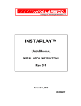
1
MANUAL,OWNERS,DF-16K
Linear P/N: 210771 C
Material: 20# White Mead Bond with 60# White Coated Cover
Ink: PMS 554 (Dark Green)
Size: 8.500" x 5.500"
Scale: 1-1
WIRELESS
SECURITY
SYSTEM
Featuring:
ensor
tatus
isplay
EMERGENCY
Owner’s Manual
Help Line: 1-800-835-2680
FRONT COVER
1 OF 40
INTRODUCTION
CONGRATULATIONS for selecting the KEEPSAFER SSD Security System. The
KEEPSAFER SSD Console incorporates many of the advanced and sophisticated
features of professionally installed systems, yet it is wireless, and you can easily
install it yourself. You can also expand and customize the KEEPSAFER SSD Security
System to fit your specific needs.
Please refer to the enclosed video tape for an easy to understand, step-by-step
installation and operation demonstration.
For a UL smoke alarm system, you must add at least one smoke detector to the
KEEPSAFER SSD Console to meet National Fire Protection Association (NFPA) Rule
74 and UL 217 requirements. Many insurance companies require you to meet
these requirements to qualify for a discount. Use only the SSD compatible smoke
detector as described in Section 3 (KEEPSAFER SSD Accessories) of this
manual.
NOTE: Some cities and municipalities may require an alarm system permit.
Check with your local authorities before installing this system.
The KEEPSAFER SSD Console and its accessories are designed and manufactured by
the oldest wireless security company in North America. You can look ahead to
many years of reliable service and peace of mind with KEEPSAFER SSD on guard for
you and your family.
In this manual, the bullets preceding the text help to define the step. For example:
# This symbol indicates a feature.
This symbol indicates an action to perform.
Q This symbol is for lighted indications or
system sounds.
This symbol is for important notes.
TECHNICAL SERVICE 24-HOUR HELP LINE
1-800-835-2680
7 DAYS-A-WEEK
INSIDE FRONT COVER
2 OF 40
MANUAL,OWNERS,DF-16K
Linear P/N: 210771 C
Material: 20# White Mead Bond with 60# White Coated Cover
Ink: PMS 554 (Dark Green)
Size: 8.500" x 5.500"
Scale: 1-1
This system is a Residential Security System. Many insurance companies offer
discounts on homeowners and renters policies when a security system is installed.
Discount credits vary with different companies and generally increase in savings
with an increase in the level of protection. Ask your insurance agent about available
savings for you.
TABLE OF CONTENTS
1. YOUR KEEPSAFER SSD SECURITY SYSTEM .
CONSOLE . . . . . . . . . . . . . . . . . . .
DOOR/WINDOW SENSORS . . . . . . . . .
WIRELESS REMOTE CONTROL . . . . . . .
.
.
.
.
.
.
.
.
.
.
.
.
.
.
.
.
.2
.3
.3
.3
2. SECURITY SYSTEM FLOOR PLAN . . . . . . . . . . . . 4
EXAMPLE SYSTEM . . . . . . . . . . . . . . . . . . . 4
DESIGN YOUR SYSTEM . . . . . . . . . . . . . . . . 4
3. KEEPSAFER SSD ACCESSORIES . . . . . . . . . . . . 5
4. CONSOLE FEATURES . . . . . . . . . . . . . . . . . . . 6
MANUAL,OWNERS,DF-16K
Linear P/N: 210771 C
Material: 20# White Mead Bond with 60# White Coated Cover
Ink: PMS 554 (Dark Green)
Size: 8.500" x 5.500"
Scale: 1-1
5. SYSTEM SENSORS . . . . . . . . . . . . . . . . . . . . 8
DOOR/WINDOW SENSOR . . . . . . . . . . . . . . . 8
WIRELESS REMOTE CONTROL . . . . . . . . . . . . 8
6. CONSOLE INSTALLATION . . . . . . . . .
PLACE CONSOLE . . . . . . . . . . . . .
ERECT ANTENNA . . . . . . . . . . . . .
PLUG IN AC ADAPTER . . . . . . . . . .
CREATE YOUR SECRET KEYPAD CODE
.
.
.
.
.
.
.
.
.
.
.
.
.
.
.
.
.
.
.
.
.
.
.
.
.
.
.
.
.
.
.9
.9
.9
10
10
7. MOUNT SENSORS . . . . . . . . . . .
SET SENSOR SWITCH . . . . . . .
APPLY DOUBLE-STICK TAPE . . .
ATTACH SENSORS AND MAGNETS
TEST SENSORS . . . . . . . . . . .
.
.
.
.
.
.
.
.
.
.
.
.
.
.
.
.
.
.
.
.
.
.
.
.
.
.
.
.
.
.
11
11
11
12
12
.
.
.
.
.
.
.
.
.
.
.
.
.
.
.
8. PREPARING THE CONSOLE . . . . . . . . . . . . . . 13
LABELING YOUR SENSORS . . . . . . . . . . . . . 13
9. DISARMING THE CONSOLE . . . . . . . . . . . . . . 14
OFF MODE . . . . . . . . . . . . . . . . . . . . . . . 14
10. USING THE SYSTEM AT HOME . . . . . . .
HOME MODE . . . . . . . . . . . . . . .
SECURE EXIT . . . . . . . . . . . . . . .
AUTOMATIC BYPASSING OF SENSORS
.
.
.
.
.
.
.
.
.
.
.
.
.
.
.
.
.
.
.
.
.
.
.
.
16. ADVANCED PROGRAMMING . . . . . . . . . . . . . 25
LEARN MODE . . . . . . . . . . . . . . . . . . . . . 25
ENTRY DELAY TIME . . . . . . . . . . . . . . . . . 25
EXIT DELAY TIME . . . . . . . . . . . . . . . . . . 25
HOME AUTOMATION OUTPUT TIME . . . . . . . . 26
REMOTE CONTROL ARMING LEVEL . . . . . . . . 26
REMOTE CONTROL DISARMING LEVEL . . . . . . 26
AUTOMATIC BYPASSING OF OPEN SENSORS . . 27
AUTOMATIC RESTORAL OF BYPASSED SENSORS 27
DISABLING QUICK ARMING . . . . . . . . . . . . . 27
EXIT DELAY BEEPS . . . . . . . . . . . . . . . . . 28
TEST SENSORS LIGHT . . . . . . . . . . . . . . . 28
HOME AUTOMATION OUTPUT POLARITY . . . . . 29
HOME AUTOMATION OUTPUT DURING EXIT/ENTRY
DELAYS . . . . . . . . . . . . . . . . . . . . . . . . 29
HOME AUTOMATION OUTPUT WHILE ARMED . . 30
HOME AUTOMATION OUTPUT FLASHES DURING
ALARM . . . . . . . . . . . . . . . . . . . . . . . . 30
HOME AUTOMATION OUTPUT FLASHES DURING
AND AFTER ALARM . . . . . . . . . . . . . . . . . 30
REMOTE CONTROL ARM/DISARM CHIRP . . . . . 31
HOME AUTOMATION ACTIVATION TONE . . . . . 31
RESTRICTED SECRET CODE . . . . . . . . . . . . 32
MASTER SECRET CODE . . . . . . . . . . . . . . 32
CONSOLE MASTER RESET . . . . . . . . . . . . . 32
17. ADVANCED PROGRAMMING TABLE . . . . . . . . . 33
18. ADDITIONAL SYSTEM ACCESSORIES . . . . . . . . 34
Evacuation Planning . . . . . . . . . . . . . . . . . . 36
15
15
16
16
11. USING THE SYSTEM WHEN LEAVING . . . . . . . . . 17
AWAY MODE . . . . . . . . . . . . . . . . . . . . . 17
AUTOMATIC BYPASSING OF SENSORS . . . . . . 18
12. USING THE SYSTEM AS DOOR CHIME . . . . . . . . 19
CHIME MODE . . . . . . . . . . . . . . . . . . . . . 19
13. BI-WEEKLY SYSTEM TESTING . . . . . . . . . . . . . 20
TEST MODE . . . . . . . . . . . . . . . . . . . . . . 20
SENSOR LOW BATTERIES . . . . . . . . . . . . . . 20
14. HOME AUTOMATION OUTPUT . . . . . . . . . . . . . 21
HOME AUTOMATION INTERFACE . . . . . . . . . . 21
PROGRAMMABLE OPTIONS . . . . . . . . . . . . . 21
15. EXPANDING YOUR SYSTEM . . . . . . . . . . . .
ADDING SENSORS TO THE SYSTEM . . . . . .
REMOVING SENSORS FROM THE SYSTEM . .
MAKING A SENSOR A 24-HOUR DOOR CHIME .
MAKING A SENSOR INTERIOR . . . . . . . . .
.
.
.
.
.
.
.
.
.
.
22
22
23
23
24
1
3 OF 40
1. YOUR KEEPSAFER SSD SECURITY SYSTEM
Your KEEPSAFER SSD Security System package consists of:
SSD
CONSOLE
VIDEO
TAPE
YARD
SIGN
REMOTE
CONTROL
DOOR/WINDOW
SENSORS
NOTE: An SSD Smoke Detector is required
to create a UL Listed smoke alarm system.
See Section 16 (Expanding Your System) for
details of how to program the SSD Smoke
Detector into the Console.
2
4 OF 40
MANUAL,OWNERS,DF-16K
Linear P/N: 210771 C
Material: 20# White Mead Bond with 60# White Coated Cover
Ink: PMS 554 (Dark Green)
Size: 8.500" x 5.500"
Scale: 1-1
# One Control Console
# Three Door/Window Sensors
# Wireless Remote Control
# One AC Power Adapter
# One Installation and Operation Video Tape
# One KEEPSAFER SSD Yard Warning Sign
CONSOLE
The KEEPSAFER SSD Console is the heart of the system. It monitors all of the system’s
wireless sensors and controls the alarm sirens.
The Console constantly monitors the condition of the system’s sensors, displaying
which protected doors and windows are open or closed. If an alarm occurs, the
Console displays which sensor caused it. When a sensor has a low battery, the
Console displays which sensor needs a new battery.
MANUAL,OWNERS,DF-16K
Linear P/N: 210771 C
Material: 20# White Mead Bond with 60# White Coated Cover
Ink: PMS 554 (Dark Green)
Size: 8.500" x 5.500"
Scale: 1-1
Two different custom secret keypad codes can be used to operate the system.
For security, a secret code must be entered to disarm (turn off) the system. The
system can be armed (turned on) by entering a secret code, or with the unique
“Quick Arm” feature.
The internal memory will “remember” your secret codes and all of the system’s
programming, even during a total power loss. An optional backup battery is
available to power the system during short power failures and is highly
recommended.
An optional Emergency Dialer can be easily installed to connect the Console to a
Central Alarm Monitoring Station through your telephone. The Emergency Dialer
is also highly recommended. With a monitored system, the central station can
dispatch authorities in case of burglary, fire or other emergency. The central
station can also call your family, friends, neighbors, or anyone else you designate
on your custom call list.
The Console has “panic button” capabilities that are always ready to operate, even
when the Console is disarmed. They can be triggered by a button on the Console,
the Wireless Keypad and portable remote controls. Pressing the [EMERGENCY] button
for two seconds will cause an immediate siren and call the central station (if the
optional dialer is installed). IMPORTANT: For personal emergency use only.
Not for use as a UL Listed Medical Alert System.
DOOR/WINDOW SENSORS
The sensors monitor your doors and windows. They send radio signals to the
Console. One type of signal is sent when the door or window is opened, and a
different type of signal is sent when the door or window is closed. If the Console
is armed, a sensor can trigger the Console’s burglary siren when its door or window
is opened. Up to 16 sensors can be used with the KEEPSAFER SSD Console.
WIRELESS REMOTE CONTROL
The wireless remote control is used to arm and disarm the Console remotely. It
can be hung on a keyring, kept in a vehicle or placed in a convenient spot so you
don’t have to go to the Console to control the system. When the Console is armed
with the remote, the Console will sound one “chirp”. When the Console is disarmed
with the remote, the Console will sound two “chirps”. NOTE: If the Console is
armed remotely with open sensors, three “chirps” will sound.
3
5 OF 40
2. SECURITY SYSTEM FLOOR PLAN
EXAMPLE SYSTEM
# The example below shows a typical
KEEPSAFER SSD system.
# Any or all of the accessories shown can be
used.
# A total of 16 sensors (including keypads) can
be used with each Console.
DESIGN YOUR SYSTEM
vulnerable to intrusion.
Figure which interior areas an intruder might
go to if unlawful entrance is gained.
Indicate locations for door window sensors,
interior motion detectors and external siren
speakers.
Decide on a centralized location for the
security Console.
ES
GB
MD
S
S
MS
WK
ENTRY
LIVING
S
S
CON - SSD CONSOLE
S - DOOR/WINDOW SENSOR
WK - WIRELESS KEYPAD
MD - MOTION DETECTOR
ES - EXTERNAL SIREN
SD - SMOKE DETECTOR
GB - GLASS BREAK SENSOR
MS - EXTERNAL MAGNETIC SWITCH
KITCHEN
S BED
DINING
S
MS
CON
MS
SD
S BATH
DEN
S
S
GARAGE
GB
MD
Example Residential Security System Floor Plan
4
6 OF 40
MANUAL,OWNERS,DF-16K
Linear P/N: 210771 C
Material: 20# White Mead Bond with 60# White Coated Cover
Ink: PMS 554 (Dark Green)
Size: 8.500" x 5.500"
Scale: 1-1
Create a floor plan of your residence.
Consider the security needs of your premises.
Determine which doors and windows are
3. KEEPSAFER SSD ACCESSORIES
(See Section 18 for detailed descriptions)
# Backup Battery
UL NOTE: Normal estimated life should
be 3 to 4 years.
MANUAL,OWNERS,DF-16K
Linear P/N: 210771 C
Material: 20# White Mead Bond with 60# White Coated Cover
Ink: PMS 554 (Dark Green)
Size: 8.500" x 5.500"
Scale: 1-1
# Remote Siren
# Smoke Detector
# Motion Detector
# One-button Key chain Remote Control
# Two-button Key chain Remote Control
# Glass break detector
# External Magnetic Switch
5
7 OF 40
4. CONSOLE FEATURES
6
4
2
1
3
5
8
7
14
13
1
12
10
11
ANTENNA
# Receives signals from the system’s sensors.
# Can be rotated towards the top of the Console case for wall mounting.
2
STATUS INDICATORS
# Indicates the status of each of the system’s sensors.
# Lights show which doors and windows are open.
# Lights flash to display sensors that have caused an alarm.
# Lights blink to show any sensors that have a low battery.
# Stick-on labels are provided to identify your custom sensor locations.
3
HINGED TOP COVER
# Flips open to access special system features.
# Can be locked closed for system security.
4
VOLUME CONTROL
# Varies the volume of the advisory tones that come from the speaker.
# Does not affect internal or accessory sirens (they are always full volume).
5
LEARN BUTTON
#
#
#
#
Used to place the Console into the Learn Mode.
Learn Mode is used to add additional sensors to the system (up to 16 total).
Your secret code can be changed using Learn Mode.
Various advanced system programming options can be made in Learn
Mode.
6
TERMINAL BLOCK
# Terminals for connection to an optional external siren speaker.
# Home Automation Output to connect to a Home Automation controller.
7
FUSE HOLDER
# Holds fuse for the backup battery.
# If the POWER light is flashing and the optional backup battery is
installed and charged, check this fuse. (Pull fuse holder straight up.)
8
BACKUP BATTERY LOCATION
# Space for optional backup battery. (Highly recommended.)
# Backup battery is automatically charged and monitored by the Console.
# Backup battery can power the Console for up to 6 hours.
6
8 OF 40
MANUAL,OWNERS,DF-16K
Linear P/N: 210771 C
Material: 20# White Mead Bond with 60# White Coated Cover
Ink: PMS 554 (Dark Green)
Size: 8.500" x 5.500"
Scale: 1-1
9
MANUAL,OWNERS,DF-16K
Linear P/N: 210771 C
Material: 20# White Mead Bond with 60# White Coated Cover
Ink: PMS 554 (Dark Green)
Size: 8.500" x 5.500"
Scale: 1-1
9
SIREN SPEAKER
# Makes unique sounds for burglary, fire and emergencies.
# Alarm siren stops automatically after five minutes.
# Sounds advisory tones to confirm keystrokes from the Console.
# Sounds mode selections tones.
# Sounds alarm memory tones.
# Beeps when Home Automation Output is activated.
# Optional external siren available for louder alarms (one or two may be used).
10
EMERGENCY BUTTON
# Pressing the [EMERGENCY] button for two seconds sounds the emergency siren.
# Can send an “emergency” message to a central monitoring station if the
optional Emergency Dialer is installed.
# Works 24-hours, even when system is disarmed.
# IMPORTANT: For personal emergency use only. Not for use as a UL
Listed Medical Alert System.
11
TEST SENSORS LIGHT
# Lights every two weeks to remind you to test the system’s sensors.
12
POWER LIGHT
#
#
#
#
13
14
Glows when AC power is on.
Dims when AC power is off and backup battery is installed.
Blinks when the optional backup battery is low, recharging or missing.
Off when AC power is off and no backup battery is installed (system
disabled).
MODE BUTTONS
# Used to control the KEEPSAFER SSD Console.
OFF
# Off Mode disarms the system.
# Switching to Off Mode stops the alarm siren.
Multiple beeps sound and status lights flash if an alarm has occurred.
Multiple beeps mean caution. AN INTRUDER MAY STILL BE IN YOUR HOME.
CHIME
# Chime Mode disarms the system.
# Switching to Chime Mode stops the alarm siren.
Multiple beeps sound and status lights flash if an alarm has occurred.
Multiple beeps mean caution. AN INTRUDER MAY STILL BE IN YOUR HOME.
# Chime Mode is for monitoring doors and windows.
Use this mode as an “automatic door chime” when at home.
Opening any protected door or window causes Console to “ding-dong”.
HOME
# Home Mode arms the perimeter sensors, but not the interior sensors.
Use this mode when anyone is staying behind.
Interior motion detectors and interior door sensors are not armed.
AWAY
# Away Mode arms the entire system.
Use this mode when leaving home.
Door sensors set for delayed will have a delay that allows you to leave and enter
the premises without sounding the alarm.
Entry Delay beeps warn you to disarm the system before the siren starts.
TEST
# Test Mode is for testing the system sensors.
All sensor status lights blink when the Test Mode is entered.
Each sensor status light will stop blinking when its sensor is tested.
# Hold the [TEST] button down to test all of the Console’s indicator lights.
KEYPAD
#
#
#
#
#
For entering your secret code (numerically or alphabetically).
Secret code must be entered before switching to Off, Test or Learn Modes.
Used when programming system options.
Press [AUTO] key to activate Home Automation Output.
Press the [∗ ] key to clear keypad if you press the wrong key.
7
9 OF 40
5. SYSTEM SENSORS
DOOR/WINDOW SENSOR
adjacent magnet.
# Opening door or window moves magnet
away, triggering sensor.
# Pressing the case causes sensor to send a
test signal.
# Sensors should be tested when the TEST
SENSORS light on the Console goes on.
# Switch on back of sensor for INSTANT or
DELAYED alarm setting.
# Red transmit light shows that battery is in
good condition.
# Internal batteries are monitored by the
Console.
# Up to 3 years battery life (depends on
frequency of activation).
# Sensor contains internal terminals for
connection to glass break detector and
external magnetic switch accessories.
WIRELESS REMOTE CONTROL
# For controlling the system without having to
go to the Console.
# Arms and disarms the Console.
# Console sounds “chirps” to indicate mode.
1 “Chirp”: Console disarm
2 “Chirps”: Console arm.
3 “Chirps”: Console arm with bypassed
open sensors.
# Up to 3 years battery life (depends on
frequency of activation).
8
10 OF 40
MANUAL,OWNERS,DF-16K
Linear P/N: 210771 C
Material: 20# White Mead Bond with 60# White Coated Cover
Ink: PMS 554 (Dark Green)
Size: 8.500" x 5.500"
Scale: 1-1
# Sensor mounts on door or window with
6. CONSOLE INSTALLATION
PLACE CONSOLE
NOTE: Sensor signals must be able to reach
1
MANUAL,OWNERS,DF-16K
Linear P/N: 210771 C
Material: 20# White Mead Bond with 60# White Coated Cover
Ink: PMS 554 (Dark Green)
Size: 8.500" x 5.500"
Scale: 1-1
EMERGENCY
BOTTOM OF
CONSOLE
LOCKING SCREW
HOLE FOR
SECURING
TOP COVER
LOCKING SCREW
HOLE FOR WALLMOUNTING
the Console.
Try to centrally locate the Console.
Keep Console away from large metal
appliances.
Maximum sensor range is 400 feet
under ideal conditions.
NOTE: If you don’t use the Wireless Keypad,
the Console should be easily accessible to
your usual entrance.
When the Console is set in the Away
Mode, you have 45 seconds to switch to
Off Mode before the burglary siren sounds.
NOTE: Make sure the Console is in a place
where you can hear the alarm during the
night hours.
Optional remote external sirens (up to
150 feet from the Console) can be
used to make alarms louder and
remote their location.
Locate the Console near a 115 VAC outlet
not controlled by a light switch.
Locate the Console within 8 feet of a
telephone outlet (for the optional Emergency
Dialer).
# A cover locking screw is provided to lock
down the hinged top cover.
If desired, the Console can be mounted on
the wall with screws.
A wall mount template is provided on
the back of the Quick Operation Guide.
NOTE: If monitoring by the central
station is desired, do not wall mount
until the Emergency Dialer is installed.
ERECT ANTENNA
FREE ANTENNA FROM CLAMPS
POSITION ANTENNA IN
UPRIGHT POSITION
EMERGENC
Free the antenna from the retaining clamps
and pivot it to the upright position.
When wall mounting the Console, pivot the
antenna so it points up when the Console is
mounted on the wall.
Y
9
11 OF 40
PLUG IN AC ADAPTER
Plug AC Adapter into the AC outlet.
Secure AC Adapter with screw to prevent
PLUG AC ADAPTER
INTO 115 VAC OUTLET
THAT IS NOT CONTROLED
BY A LIGHT SWITCH
un-plugging.
IMPORTANT: Be sure to plug the AC
adapter into a 115 VAC outlet that is not
controlled by a wall switch.
SCREW
115 VAC
OUTLET
CREATE YOUR SECRET KEYPAD CODE
# When power is first applied, a secret code
START HERE
must be entered.
NOTE: Your secret code must be entered on
the Console’s keypad, not the wireless
keypad.
Choose a one to five digit secret code to use
for arming and disarming the Console.
CHOOSE
A SECRET
NOTE: For maximum security, a three to
CODE
five digit code is recommended.
Press [∗ ] (clears keypad if any other keys
have been pressed).
Enter any combination of 1-5 digits for your
OFF
secret code, then press [OFF].
Test your new secret code by entering it then
pressing [TEST].
DONE
# Don’t forget your secret code, write it down.
NOTE: If you forget your code, see the
Advanced Programming section of this
START HERE
manual.
# The Console will treat your secret code as a
“master” secret code. To create a
“restricted” secret code, see the Advanced
Programming section of this manual.
TEST YOUR
NOTE: The master secret code can be used
SECRET
to enter Learn Mode. The restricted secret
CODE
code cannot.
To prepare for the sensor installation, place
the system in Chime Mode by entering your
secret code and pressing [CHIME].
TEST
DONE
10
12 OF 40
MANUAL,OWNERS,DF-16K
Linear P/N: 210771 C
Material: 20# White Mead Bond with 60# White Coated Cover
Ink: PMS 554 (Dark Green)
Size: 8.500" x 5.500"
Scale: 1-1
AC ADAPTER
7. MOUNT SENSORS
MANUAL,OWNERS,DF-16K
Linear P/N: 210771 C
Material: 20# White Mead Bond with 60# White Coated Cover
Ink: PMS 554 (Dark Green)
Size: 8.500" x 5.500"
Scale: 1-1
SENSOR
ON FRAME
MAGNET
ON DOOR
MAGNET
ON WINDOW
SENSOR
ON FRAME
SET SENSOR SWITCH
# A switch on the bottom of the door/window
sensor selects instant or delayed response.
If the sensor is going to be used on your
primary entry/exit door make sure that the
switch is in the DELAYED position.
If the sensor is going to be used on a
window or a door that is not going to be
used to enter and exit the premises, slide the
sensor switch to INSTANT.
SLIDE SWITCH
TO THE INSTANT
OR DELAYED
POSITION
APPLY DOUBLE-STICK TAPE
APPLY
DOUBLE-STICK
TAPE TO BACK
OF SENSOR
AND MAGNET
MOUNTING
PLATES
Apply double-stick tape (supplied) to back of
sensors and magnets.
# Screws are also provided to mount sensors
and magnets.
# Screws are preferred over the double-stick
tape in permanent installations.
NOTE: Double-stick tape is not allowed in
UL installations.
11
13 OF 40
ATTACH SENSORS AND MAGNETS
On doors, mount sensor to door frame and
magnet to door.
NOTE: Magnet must line up with mark on
sensor case both horizontally & vertically.
Allow a maximum of 1/2" between magnet
and sensor when door/window is closed.
Snap sensor onto mounting plate.
MOUNT SENSOR
PLATE TO FRAME
1/2" MAXIMUM
SPACE BETWEEN
SENSOR AND
MAGNET PLATES
ALIGN MAGNET
PLATE NEXT TO
SENSOR PLATE
AND ATTACH TO
DOOR
MOUNT SENSOR
PLATE TO FRAME
ALIGN MAGNET
PLATE NEXT TO
SENSOR PLATE
AND ATTACH TO
WINDOW
SPACE BELOW
PLATE IS REQUIRED
TO SNAP SENSOR
ONTO PLATE
On windows, mount sensor to window frame
and magnet to window.
Snap sensor onto mounting plate.
1/2" MINIMUM
SNAP SENSOR ONTO
MOUNTING PLATE
USE SPACER WHEN
SURFACES ARE
UNEVEN
Use optional magnet spacer when surfaces
are uneven.
HOOK SPACER TO
MAGNET PLATE
AND ROTATE TO
LOCK IN PLACE
TEST SENSORS
SENSOR LIGHT
SHOULD
GLOW FOR
TWO SECONDS
OPEN DOOR
OR WINDOW
Open door or window.
Q Verify that light on the sensor glows
momentarily when door/window is opened.
Q Console in Chime Mode should “ding-dong”
when the sensor sends signal.
CONSOLE IN
CHIME MODE
SHOULD DING-DONG
Q Status indicator on Console should remain
STATUS INDICATOR
SHOULD LIGHT
WHEN SENSOR IS OPEN
1
EMERGENCY
lit for each door/window sensor that is left
open.
NOTE: The three door/window sensors
supplied with the Console are
pre-programmed into the Console’s memory
as sensors #1, #2 and #3.
12
14 OF 40
MANUAL,OWNERS,DF-16K
Linear P/N: 210771 C
Material: 20# White Mead Bond with 60# White Coated Cover
Ink: PMS 554 (Dark Green)
Size: 8.500" x 5.500"
Scale: 1-1
SNAP SENSOR ONTO
MOUNTING PLATE
8. PREPARING THE CONSOLE
LABELING YOUR SENSORS
# The two sensors provided are
USE LABELS PROVIDED
TO IDENTIFY SENSORS
MANUAL,OWNERS,DF-16K
Linear P/N: 210771 C
Material: 20# White Mead Bond with 60# White Coated Cover
Ink: PMS 554 (Dark Green)
Size: 8.500" x 5.500"
Scale: 1-1
EMERGENCY
pre-programmed as sensors 01, 02 and 03.
# A label sheet with sensor location names is
provided with the Console.
Open one protected door/window.
Choose a label that describes the sensor
location, or write the location on a blank
label, and stick it in the area to the right of
the sensor light.
Close the protected opening that you just
labeled.
Repeat for each protected opening.
Stick the REMOTE CONTROL label in the
spot for sensor 16.
13
15 OF 40
9. DISARMING THE CONSOLE
OFF MODE
START HERE
(OPTIONAL)
YOUR
SECRET
CODE
OFF
1 GONG
DONE
of the system.
# Switching to Off Mode stops any alarms in
progress.
# The 24-hour emergency functions are still
active in Off Mode and can be triggered by
pressing the [EMERGENCY] button.
Switch to Off Mode by entering your secret
code, and pressing [OFF].
Q When the system is disarmed to Off Mode,
the Console will sound one “Gong”.
Q If an alarm has occurred, multiple beeps will
sound after disarming and the sensor light
for the sensor(s) that caused the alarm will
flash.
NOTE: In Off Mode, protected doors and
windows cannot trigger the burglary alarm.
14
16 OF 40
MANUAL,OWNERS,DF-16K
Linear P/N: 210771 C
Material: 20# White Mead Bond with 60# White Coated Cover
Ink: PMS 554 (Dark Green)
Size: 8.500" x 5.500"
Scale: 1-1
# Use this mode to disarm the burglary portion
10. USING THE SYSTEM AT HOME
HOME MODE
# Use this mode when sleeping or when
START HERE
(OPTIONAL)
MANUAL,OWNERS,DF-16K
Linear P/N: 210771 C
Material: 20# White Mead Bond with 60# White Coated Cover
Ink: PMS 554 (Dark Green)
Size: 8.500" x 5.500"
Scale: 1-1
YOUR
SECRET
CODE
HOME
1 GONG &
2 BEEPS
DONE
START HERE
HOLD
HOME DOWN
1 GONG &
2 BEEPS
DONE
anyone is staying inside.
# Home Mode causes an instant alarm when
any perimeter sensor switched to INSTANT
is triggered.
# Home Mode causes a delayed alarm when
any perimeter sensor switched to DELAYED
is triggered.
# Alarm siren stops automatically after five
minutes and the system will remain armed.
# Home Mode ignores all interior sensors
(optional interior motion detectors).
Arm to Home Mode by entering your secret
code, and pressing [HOME].
You can “Quick Arm” to Home Mode from
Off or Chime Mode by holding down the
[HOME] key for two seconds. (Quick arming
can be disabled; see the Advanced
Programming Section of this manual.)
Q When the system is armed to the Home
Mode, the Console will sound a “Gong” and
two “Beeps”.
Enter your secret code and press [OFF] or
[CHIME] to disarm from Home Mode and/or
stop the alarm siren.
Q If an alarm has occurred, multiple beeps will
sound after disarming and the sensor light
for the sensor(s) that caused the alarm will
flash (switch to Off Mode again to stop
flashing alarm memory light).
15
17 OF 40
SECURE EXIT
and you want to exit the premises while
leaving someone inside with the system still
in Home Mode, press the [HOME] key for two
seconds.
Q A “gong” and two “beeps” will sound and the
HOME light will blink for 30 seconds.
# You can leave through a door with a delayed
perimeter sensor during the 30 second Exit
Delay without causing the Console to begin
an Entry Delay.
NOTE: The Exit Delay time can be changed;
see the Advanced Programming section of
this manual.
AUTOMATIC BYPASSING OF SENSORS
# The Console can be armed with open door
or window sensors.
# The system will automatically “bypass” open
doors and windows after sounding four
high-low beeps to warn you that a protected
door or window is open.
Q Lit sensor status indicators show which
sensors are open.
# Bypassed sensors cannot cause an alarm
until they are “restored” (closed).
If you close the door or window after arming
the system, the sensor will be restored and
can cause an alarm the next time it is
opened.
# Automatic bypassing of sensors in the Home
Mode allows you to arm the system at night
with open windows, while still having
perimeter protection with other closed doors
and windows.
16
18 OF 40
MANUAL,OWNERS,DF-16K
Linear P/N: 210771 C
Material: 20# White Mead Bond with 60# White Coated Cover
Ink: PMS 554 (Dark Green)
Size: 8.500" x 5.500"
Scale: 1-1
If the system is already in the Home Mode
11. USING THE SYSTEM WHEN LEAVING
AWAY MODE
START HERE
(OPTIONAL)
MANUAL,OWNERS,DF-16K
Linear P/N: 210771 C
Material: 20# White Mead Bond with 60# White Coated Cover
Ink: PMS 554 (Dark Green)
Size: 8.500" x 5.500"
Scale: 1-1
YOUR
SECRET
CODE
AWAY
1 GONG &
3 BEEPS
DONE
START HERE
HOLD
AWAY DOWN
1 GONG &
3 BEEPS
DONE
# Use this mode when no one will be staying
home.
# Away Mode causes an instant alarm when
any perimeter sensor switched to INSTANT
is triggered.
# Away Mode causes a delayed alarm when
any perimeter sensor switched to DELAYED
is triggered.
# Away Mode causes an instant alarm when
any interior sensors (optional interior motion
detectors) are triggered. The interior sensors
will be delayed if a perimeter delayed sensor
is triggered first.
# Alarm siren stops automatically after five
minutes and the system will remain armed
This can occur an unlimited number of times.
Arm to Away Mode by entering your secret
code, and pressing [AWAY].
You can “Quick Arm” to Away Mode from
Home, Chime or Off Mode by holding down
the [AWAY] key for two seconds. (Quick
arming can be disabled; see the Advanced
Programming Section of this manual.)
EXIT DELAY (For Leaving the Premises)
Q When the system is armed to the Away
Mode, the Console will sound a “Gong” and
three “Beeps”.
Q During the 30 second Exit Delay, the
Console will sound “beeps” and the AWAY
light will blink.
# The Exit Delay gives you 30 seconds to leave
the premises through a delayed perimeter
door without triggering an alarm.
Q When the Exit Delay is over, the Console will
sound one “gong” to warn you that the
system is fully armed.
NOTE: The Exit Delay time can be changed;
see the Advanced Programming Section of
this manual.
30
SECONDS
17
19 OF 40
ENTRY DELAY (For Entering the Premises)
# The Entry Delay gives you 45 seconds to
enter the premises through a delayed
perimeter door without triggering an alarm.
# If a perimeter delayed sensor is triggered,
starting the Entry Delay, the interior sensors
will also become delayed (this allows motion
in the premises during the Entry Delay).
Q During the 45 second Entry Delay, the
Console will sound “beeps”.
# When the Entry Delay is over, the Console
will go into full alarm and sound the siren if it
is not disarmed to the Off or Chime Mode.
If an alarm has occurred while you
were gone, multiple beeps will sound
after disarming and the sensor light for
the sensor(s) that caused the alarm will
flash (switch to Off Mode again to stop
flashing alarm memory light).
☞If you hear the multiple beeps, use
caution when entering. AN
INTRUDER MAY STILL BE IN YOUR
HOME.
NOTE: The Entry Delay time can be
changed; see the Advanced Programming
Section of this manual.
AUTOMATIC BYPASSING OF SENSORS
# The Console can be armed with open door
or window sensors.
Q The system will automatically “bypass” open
doors and windows after sounding four
high-low beeps to warn you that a protected
door or window is open.
Q Lit sensor status indicators show which
sensors are open.
NOTE: Bypassed sensors cannot cause an
alarm until they are “restored”.
# If you close the door or window after arming
the system, the sensor will be restored and can
cause an alarm the next time it is opened.
# Automatic bypassing of sensors in the Away
Mode allows you to arm the system with
open doors and windows, while still having
perimeter protection with other closed doors
and windows.
18
20 OF 40
MANUAL,OWNERS,DF-16K
Linear P/N: 210771 C
Material: 20# White Mead Bond with 60# White Coated Cover
Ink: PMS 554 (Dark Green)
Size: 8.500" x 5.500"
Scale: 1-1
45
SECONDS
12. USING THE SYSTEM AS DOOR CHIME
CHIME MODE
START HERE
(OPTIONAL)
MANUAL,OWNERS,DF-16K
Linear P/N: 210771 C
Material: 20# White Mead Bond with 60# White Coated Cover
Ink: PMS 554 (Dark Green)
Size: 8.500" x 5.500"
Scale: 1-1
YOUR
SECRET
CODE
CHIME
1 GONG &
1 BEEP
DONE
# Chime Mode is for monitoring entries and
exits without causing alarms.
# Use Chime Mode as an “automatic door
chime” when at home.
Q Opening any protected door or window
causes the Console to sound a “ding-dong”.
Select the Chime Mode by entering your
secret code, then press [CHIME].
You can enter Chime Mode from Off Mode
by holding down the [CHIME] key for two
seconds.
Q When the system is switched to the Chime
Mode, the Console will sound a “Gong” and
one “Beep”.
# Going to Chime Mode disarms the system
and stops any alarms in progress.
NOTE: In Chime Mode, protected doors and
windows cannot trigger the burglary alarm.
START IN OFF
HOLD
CHIME DOWN
1 GONG &
1 BEEP
DONE
19
21 OF 40
13. BI-WEEKLY SYSTEM TESTING
TEST MODE
(OPTIONAL)
YOUR
SECRET
CODE
TEST
1 GONG &
4 BEEPS
DONE
you should test each sensor in the system.
# The Console must be in Off Mode before
going to Test Mode.
Switch the Console into Test Mode by
entering your secret code and pressing [TEST].
Q When the system is switched to the Test
Mode, the Console will sound a “Gong” and
four “Beeps”.
Q Placing the system in Test Mode will turn the
TEST SENSORS light off.
Holding down the [TEST] button will light all of
the Console’s indicators.
Q The sensor status lights will flash for each
sensor programmed into the Console.
Go to each sensor and press its test button
or open and close the protected opening.
To test the wireless keypad, press the [AUTO]
key.
Q As each sensor is tested, the sensor status
light for the sensor will stop flashing and
return to showing the current status of the
sensor.
Q The Console will make a “bing” sound as
each sensor is tested.
Continue testing until there are no flashing
status lights.
NOTE: If the Console is left unattended in
Test Mode, it will automatically switch back
to Off Mode after 3 minutes.
SENSOR LOW BATTERIES
Q When a sensor’s status light on the Console
WHEN CONSOLE INDICATES A SENSOR
LOW BATTERY, OPEN SENSOR CASE AND
GENTLY LIFT UP END OF BATTERY CLAMP,
SLIDE BATTERIES OUT
NOTE: USE OF EXCESSIVE FORCE ON
BATTERY CLAMP WILL RESULT IN DAMAGE
LIFT
+
+
-
blinks, the sensor has a low battery.
NOTE: Don’t confuse a blinking status light
with a flashing status light (flashing light is
faster and indicates alarm memory).
Refer to the figure when replacing
door/window sensor batteries.
INSTALL TWO
DURACELL
TYPE DL 2032
BATTERIES (+)
SIDE UP
IF NECESSARY
PUSH IN SLOT TO REMOVE
SENSOR FROM MOUNTING PLATE
REMOVE BATTERIES
FROM THIS END
20
22 OF 40
MANUAL,OWNERS,DF-16K
Linear P/N: 210771 C
Material: 20# White Mead Bond with 60# White Coated Cover
Ink: PMS 554 (Dark Green)
Size: 8.500" x 5.500"
Scale: 1-1
Q When the TEST SENSORS light comes on,
START HERE
14. HOME AUTOMATION OUTPUT
MANUAL,OWNERS,DF-16K
Linear P/N: 210771 C
Material: 20# White Mead Bond with 60# White Coated Cover
Ink: PMS 554 (Dark Green)
Size: 8.500" x 5.500"
Scale: 1-1
HOME AUTOMATION INTERFACE
# The Console provides a Home Automation
Output to control lights, devices and
appliances.
# Home Automation Output can connect to
most popular home automation devices and
other simple electronic devices.
Press [AUTO] to turn the Home Automation
Output on, press [AUTO] again to turn it off.
MINUS TERMINAL WILL SWITCH
TO GROUND WHEN HOME
AUTOMATION OUTPUT
IS ACTIVATED
HOME AUTOMATION
OUTPUT TERMINALS
(INSIDE CONSOLE)
LEARN
POSITIVE TERMINAL PROVIDES
+12 VOLTS DC AND IS CURRENT
LIMITED AT 30 MILLIAMPS MAXIMUM
EXAMPLE HOME AUTOMATION HOOK-UPS
X-10
X-10
BURGLAR ALARM
INTERFACE
(CAN CONTROL
HOUSE LIGHTS
THROUGH X-10
SYSTEM)
RB-90
RELAY MODULE
YOUR
LOAD
LIGHT
EMITTING
DIODE
(L.E.D.)
POWER
SOURCE
PROGRAMMABLE OPTIONS
# There are many programmable options for
the Home Automation Output. See the
Advanced Programming Section of this
manual for details.
21
23 OF 40
15. EXPANDING YOUR SYSTEM
# Adding additional sensors will increase the
protection provided by your system.
# All ground-level perimeter openings and
ADDING SENSORS TO THE SYSTEM
Always start with the Console in Off Mode
(enter your secret code and press [OFF]).
START IN OFF
Enter your secret code and press the [LEARN]
button.
Q
A “gong” and five “beeps” will sound.
YOUR
Q The sensor status indicators will light for
SECRET
each sensor programmed into the Console.
CODE
Enter an unused sensor number from 01-16
(you must enter two digits, example: 5 = 05)
Q The sensor indicator light will flash for the
sensor number selected.
1 GONG &
Activate the sensor. (To add wireless
5 BEEPS
keypads, press the keypad’s [AUTO] key.)
Q A single “bing” tone will sound when the
NEW
sensor is learned by the Console.
SENSOR
Q A double “buzz” tone will sound if there is
NUMBER
already another sensor programmed to that
sensor number.
Exit Learn Mode by holding the [OFF] button
ACTIVATE
for three seconds.
SENSOR
NOTE: A senosr can be learned into more
than one location. Be sure to choose an
DONE
unused sensor number. If a sensor gets
entered into more than one location, delete
the duplicates. (See “Removing Sensors
from the System”).
22
24 OF 40
MANUAL,OWNERS,DF-16K
Linear P/N: 210771 C
Material: 20# White Mead Bond with 60# White Coated Cover
Ink: PMS 554 (Dark Green)
Size: 8.500" x 5.500"
Scale: 1-1
accessible upper-story openings need
protection.
# Motion detectors can protect interior areas
and areas were valuables are kept.
# Wireless sensors make protecting a
detached garage easy (no wires to run).
# Each sensor has a unique ID code that is
recognized by the Console.
MANUAL,OWNERS,DF-16K
Linear P/N: 210771 C
Material: 20# White Mead Bond with 60# White Coated Cover
Ink: PMS 554 (Dark Green)
Size: 8.500" x 5.500"
Scale: 1-1
REMOVING SENSORS FROM THE SYSTEM
# If a previously learned sensor isn’t going to
START IN OFF
be used with the system anymore, it should
be removed from the Console’s memory.
#
Start with the Console in Off Mode.
YOUR
#
Enter your secret code and press the [LEARN]
SECRET
button.
CODE
Q A “gong” and five “beeps” will sound.
Q The sensor status indicators will light for
each sensor programmed into the Console.
1 GONG &
Enter the sensor number (from 01-16) that
5 BEEPS
you want to remove (you must enter two
digits, example: 5 = 05)
SENSOR
Q The sensor indicator light will flash for the
NUMBER
sensor number selected.
TO REMOVE
Press the [TEST] button.
Q A single “bing” tone will sound when the
TEST 1 BING
sensor has been removed and the sensor
status indicator will turn off.
Exit Learn Mode by holding the [OFF] button
DONE
for three seconds.
MAKING A SENSOR A 24-HOUR DOOR CHIME
# Sensors can be programmed to cause the
START IN OFF
Console to chime any time they’re activated.
# Chime-only sensors will not be able to
trigger the alarm in any Console mode.
YOUR
SECRET
# The sensor must have already been learned
CODE
by the Console (see “Adding sensors to the
System” for details).
Start with the Console in Off Mode.
1 GONG &
Enter your secret code and press the [LEARN]
5 BEEPS
button.
Q A “gong” and five “beeps” will sound.
SENSOR
Q The sensor status indicators will light for
NUMBER
each sensor programmed into the Console.
FOR CHIME
Enter the sensor number from 01-16 (you
must enter two digits, example: 5 = 05)
HOME
Q The sensor indicator light will flash for the
sensor number selected.
8 TU V
Press [HOME], 8, then [AWAY]. A “bing” tone
will sound.
AWAY 1 BING
Exit Learn Mode by holding the [OFF] button
for three seconds.
DONE
23
25 OF 40
MAKING A SENSOR INTERIOR
YOUR
SECRET
CODE
1 GONG &
5 BEEPS
SENSOR
NUMBER
FOR
INTERIOR
HOME
AWAY
1 BING
# Motion detectors are automatically
programmed as interior sensors. Any other
sensor can also be programmed as an
interior sensor.
# Interior sensors can only trigger an alarm
when the Console is in Away Mode.
# The sensor must have already been learned
by the Console (see “Adding sensors to the
System” for details).
Start with the Console in Off Mode.
Enter your secret code and press the [LEARN]
button.
Q A “gong” and five “beeps” will sound.
Q The sensor status indicators will light for
each sensor programmed into the Console.
Enter the sensor number from 01-16 (you
must enter two digits, example: 5 = 05)
Q The sensor indicator light will flash for the
sensor number selected.
Press [HOME], 7, then [AWAY]. A “bing” tone
will sound.
Exit Learn Mode by holding the [OFF] button
for three seconds.
DONE
24
26 OF 40
MANUAL,OWNERS,DF-16K
Linear P/N: 210771 C
Material: 20# White Mead Bond with 60# White Coated Cover
Ink: PMS 554 (Dark Green)
Size: 8.500" x 5.500"
Scale: 1-1
START IN OFF
16. ADVANCED PROGRAMMING
LEARN MODE
# To perform any of the advanced
START IN OFF
MANUAL,OWNERS,DF-16K
Linear P/N: 210771 C
Material: 20# White Mead Bond with 60# White Coated Cover
Ink: PMS 554 (Dark Green)
Size: 8.500" x 5.500"
Scale: 1-1
YOUR
SECRET
CODE
1 GONG &
5 BEEPS
LEARN MODE
programming steps, the Console must be in
the Learn Mode.
Start with the Console in Off Mode (Learn
Mode cannot be reached from any other
mode).
Enter Learn Mode by entering your secret
code and pressing the [LEARN] button.
NOTE: Only the master secret code can be
used to put the Console into the Learn
Mode. The restricted secret code cannot
access Learn Mode.
Q A “gong” and five “beeps” will sound,
signaling that the Console is in Learn Mode.
Hold the [OFF] key for three seconds when
you want to exit Learn Mode.
NOTE: If the Console is left unattended in
Learn Mode, it will automatically switch back
to Off Mode after three minutes.
ENTRY DELAY TIME
# The factory-set Entry Delay time is 45
PROGRAMMING STEP #20
PROGRAM
TIME IN SECONDS (1-255)
STORE PROGRAM
seconds.
# The Entry Delay time can be adjusted from
one to 255 seconds.
NOTE: Don’t make your Entry Delay too
short. You may not have enough time to
disarm the system before an alarm.
# The Console must be in Learn Mode to
make this change.
Exit Learn Mode when all programming
changes are complete.
EXIT DELAY TIME
PROGRAMMING STEP #21
# The factory-set Exit Delay time is 30 seconds.
# The Exit Delay time can be adjusted from
one to 255 seconds.
PROGRAM
# The Console must be in Learn Mode to
TIME IN SECONDS (1-255)
Exit Learn Mode when all programming
STORE PROGRAM
make this change.
changes are complete.
25
27 OF 40
HOME AUTOMATION OUTPUT TIME
# The factory setting causes the Home
Automation Output to toggle between on
PROGRAMMING STEP #40
and off with each activation.
#
The Home Automation Output can be
PROGRAM
programmed to turn on, then automatically
TIME IN SECONDS (1-2500)
turn off after one to 2500 seconds (42
0 = TOGGLE ON & OFF
minutes).
# The Console must be in Learn Mode to
STORE PROGRAM
make this change.
Exit Learn Mode when all programming
REMOTE CONTROL ARMING LEVEL
# The factory setting causes the portable
remote controls to arm to the Away Mode.
PROGRAMMING STEP #50
# Alternately, the portable remote controls can
arm to the Home Mode.
PROGRAM
# Changing this setting will affect all the
2 FOR HOME MODE
portable remote controls used with the
3 FOR AWAY MODE
system.
STORE PROGRAM
# The Console must be in Learn Mode to
make this change.
Exit Learn Mode when all programming
changes are complete.
REMOTE CONTROL DISARMING LEVEL
# The factory setting causes the portable
remote controls and wireless keypads to
PROGRAMMING STEP #51
disarm to the Off Mode.
# Alternately, the remote controls and wireless
PROGRAM
keypads can disarm to the Chime Mode.
0 FOR OFF MODE
#
Changing this setting will affect all the
1 FOR CHIME MODE
portable remote controls and wireless
STORE PROGRAM
keypads used with the system.
# The Console must be in Learn Mode to
make this change.
Exit Learn Mode when all programming
changes are complete.
26
28 OF 40
MANUAL,OWNERS,DF-16K
Linear P/N: 210771 C
Material: 20# White Mead Bond with 60# White Coated Cover
Ink: PMS 554 (Dark Green)
Size: 8.500" x 5.500"
Scale: 1-1
changes are complete.
MANUAL,OWNERS,DF-16K
Linear P/N: 210771 C
Material: 20# White Mead Bond with 60# White Coated Cover
Ink: PMS 554 (Dark Green)
Size: 8.500" x 5.500"
Scale: 1-1
AUTOMATIC BYPASSING OF OPEN SENSORS
# The factory setting causes the Console to
automatically bypass any open sensors when
PROGRAMMING STEP #60
the system is armed.
#
Alternately, the Console can be programmed
PROGRAM
to not arm on the first attempt if there are
0 FOR AUTO BYPASS OFF
any open sensors.
1 FOR AUTO BYPASS ON
#
If automatic bypassing is turned off, and
STORE PROGRAM
arming is attempted with open sensors, the
Console will sound five two-tone beeps and
will not arm.
# Arming to the same mode again within five
seconds will bypass any open sensors and
arm the Console.
# The Console must be in Learn Mode to
make this change.
Exit Learn Mode when all programming
changes are complete.
AUTOMATIC RESTORAL OF BYPASSED SENSORS
# If a sensor is open when the system is
armed, the Console will bypass it.
PROGRAMMING STEP #61
# The factory setting causes the Console to
automatically restore (remove the bypass
PROGRAM
from) any bypassed sensor when the sensor
0 FOR AUTO RESTORAL OFF
closes. After it’s restored, the sensor is ready to
1 FOR AUTO RESTORAL ON
cause an alarm the next time it is opened.
STORE PROGRAM
# Alternately, the Console can be programmed
to not automatically restore sensors that close.
Bypassed sensors will remain bypassed until
the system is disarmed.
# The Console must be in Learn Mode to
make this change.
Exit Learn Mode when all programming
changes are complete.
DISABLING QUICK ARMING
# The factory setting allows the Console to be
PROGRAMMING STEP #62
PROGRAM
0 FOR QUICK ARMING OFF
1 FOR QUICK ARMING ON
STORE PROGRAM
armed by holding down the mode keys for
two seconds.
# Alternately, the Console can be programmed
to not allow quick arming.
# If quick arming is disabled, your secret code
must be entered before pressing the mode
buttons.
Exit Learn Mode when all programming
changes are complete.
27
29 OF 40
EXIT DELAY BEEPS
# The factory setting causes the Console to
PROGRAMMING STEP #65
PROGRAM
0 FOR EXIT BEEPS OFF
1 FOR EXIT BEEPS ON
STORE PROGRAM
beep during Exit Delays.
# Alternately, the Exit Delay beeps can be
silenced.
# The Console will be silent after arming to the
Away Mode until the Exit Delay expires, then
a single “gong” tone will sound.
# The Console must be in Learn Mode to
make this change.
Exit Learn Mode when all programming
changes are complete.
# The factory setting causes the Console’s
PROGRAMMING STEP #67
PROGRAM
0 FOR TEST SENSORS OFF
1 FOR TEST SENSORS ON
STORE PROGRAM
TEST SENSORS indicator to light every two
weeks.
# Alternately, the TEST SENSORS light can be
disabled.
# The Console must be in Learn Mode to
make this change.
Exit Learn Mode when all programming
changes are complete.
28
30 OF 40
MANUAL,OWNERS,DF-16K
Linear P/N: 210771 C
Material: 20# White Mead Bond with 60# White Coated Cover
Ink: PMS 554 (Dark Green)
Size: 8.500" x 5.500"
Scale: 1-1
TEST SENSORS LIGHT
MANUAL,OWNERS,DF-16K
Linear P/N: 210771 C
Material: 20# White Mead Bond with 60# White Coated Cover
Ink: PMS 554 (Dark Green)
Size: 8.500" x 5.500"
Scale: 1-1
HOME AUTOMATION OUTPUT POLARITY
# The factory setting causes the Console’s
Home Automation Output to provide a
PROGRAMMING STEP #68
current limited voltage source when
activated.
PROGRAM
# Alternately, the Console can be programmed
0 FOR VOLTAGE WHEN OFF
so the Home Automation Output provides a
1 FOR VOLTAGE WHEN ON
current limited voltage source when
STORE PROGRAM
deactivated.
# The Console must be in Learn Mode to
make this change.
Exit Learn Mode when all programming
changes are complete.
HOME AUTOMATION OUTPUT DURING EXIT/ENTRY DELAYS
# The factory setting causes the Console’s
Home Automation Output to activate when
PROGRAMMING STEP #69
pressing the [AUTO] key, or when it’s triggered
with a two-button remote control.
PROGRAM
# In addition, the Console can be
0 FOR STANDARD TRIGGER
programmed to activate the Home
1 FOR OUTPUT DURING DELAYS
Automation Output during the exit and Entry
STORE PROGRAM
Delays.
# The Console must be in Learn Mode to
make this change.
Exit Learn Mode when all programming
changes are complete.
29
31 OF 40
HOME AUTOMATION OUTPUT FLASHES DURING ALARM
# The factory setting causes the Console’s
Home Automation Output to activate when
PROGRAMMING STEP #71
pressing the [AUTO] key, or when it’s triggered
with a two-button remote control.
PROGRAM
# In addition, the Console can be
0 FOR STANDARD TRIGGER
programmed to flash the Home Automation
1 FOR FLASHING OUTPUT ON ALARM
Output during alarms.
STORE PROGRAM
# The Console must be in Learn Mode to
make this change.
Exit Learn Mode when all programming
changes are complete.
HOME AUTOMATION OUTPUT FLASHES DURING AND AFTER ALARM
# The factory setting causes the Console’s
Home Automation Output to activate when
PROGRAMMING STEP #72
pressing the [AUTO] key, or when it’s triggered
with a two-button remote control.
PROGRAM
# In addition, the Console can be
0 FOR STANDARD TRIGGER
programmed to flash the Home Automation
1 FOR FLASHING ON & AFTER ALARM
Output during and after any alarms.
STORE PROGRAM
# The output will continue to flash until the
flashing status lights are cleared.
# The Console must be in Learn Mode to
make this change.
Exit Learn Mode when all programming
changes are complete.
30
32 OF 40
MANUAL,OWNERS,DF-16K
Linear P/N: 210771 C
Material: 20# White Mead Bond with 60# White Coated Cover
Ink: PMS 554 (Dark Green)
Size: 8.500" x 5.500"
Scale: 1-1
HOME AUTOMATION OUTPUT WHILE ARMED
# The factory setting causes the Console’s
Home Automation Output to activate when
PROGRAMMING STEP #70
pressing the [AUTO] key, or when it’s triggered
with a two-button remote control.
PROGRAM
#
In addition, the Console can be
0 FOR STANDARD TRIGGER
programmed to activate the Home
1 FOR OUTPUT WHEN ARMED
Automation Output when the system is
STORE PROGRAM
armed.
# The Console must be in Learn Mode to
make this change.
Exit Learn Mode when all programming
changes are complete.
MANUAL,OWNERS,DF-16K
Linear P/N: 210771 C
Material: 20# White Mead Bond with 60# White Coated Cover
Ink: PMS 554 (Dark Green)
Size: 8.500" x 5.500"
Scale: 1-1
REMOTE CONTROL ARM/DISARM CHIRP
# When arming with the portable remote
control, the factory setting causes the
PROGRAMMING STEP #73
Console to “chirp” once when armed, twice
when disarmed, and three times when
PROGRAM
arming with sensors bypassed.
0 FOR CHIRPS OFF
# Alternately, these chirps can be silenced.
1 FOR CHIRPS ON
# If these chirps are silenced, it is
STORE PROGRAM
recommended to program the Home
Automation Output to be active when the
system is armed, so a light can be triggered
displaying the arming status of the Console.
# The Console must be in Learn Mode to
make this change.
Exit Learn Mode when all programming
changes are complete.
HOME AUTOMATION ACTIVATION TONE
# The factory setting causes the Console to
sound a “bing” when the Home Automation
PROGRAMMING STEP #74
Output is activated by pressing the [AUTO]
key, or when it’s triggered with a two-button
PROGRAM
remote control.
0 FOR BING TONE OFF
#
Alternately, this sound can be silenced.
1 FOR BING TONE ON
#
The Console must be in Learn Mode to
STORE PROGRAM
make this change.
Exit Learn Mode when all programming
changes are complete.
31
33 OF 40
RESTRICTED SECRET CODE
PROGRAM
1-5 DIGIT RESTRICTED CODE
(3-5 DIGITS RECOMMENDED)
STORE PROGRAM
PROGRAMMING STEP #98
REMOVES RESTRICTED
SECRET CODE
# The Console can be programmed with two
secret codes, one that can access Learn
Mode and one that cannot.
# The restricted secret code cannot access
Learn Mode, the master secret code can.
# The restricted secret code is a good one to
give to children or any user that you want to
restrict from programming the Console.
NOTE: For maximum security, a 3-5 digit
code is recommended.
# The Console must be in Learn Mode to
make or change the restricted secret code.
Exit Learn Mode when all programming
changes are complete.
MASTER SECRET CODE
PROGRAMMING STEP #99
PROGRAM
1-5 DIGIT MASTER CODE
(3-5 DIGITS RECOMMENDED)
STORE PROGRAM
# The master secret code is the code that was
entered when power was first applied to the
Console.
# The master secret code can be changed
through programming to any 1-5 digit code.
NOTE: For maximum security, a 3-5 digit
code is recommended.
# The Console must be in Learn Mode to
make or change the master secret code.
Exit Learn Mode when all programming
changes are complete.
CONSOLE MASTER RESET
# Master resetting the Console will set all of the
programming options back to the factory
values.
NOTE: Master resetting the Console will
erase the master and restricted secret codes
and remove all programmed sensors.
Disconnect the backup battery (if installed).
Un-plug the Console’s wall transformer.
Press and hold down the [LEARN] button while
plugging in the wall transformer.
Release the [LEARN] button.
Create your secret code as described on
Page 10.
Re-connect the backup battery (if installed).
Re-program each sensor into the system.
32
34 OF 40
MANUAL,OWNERS,DF-16K
Linear P/N: 210771 C
Material: 20# White Mead Bond with 60# White Coated Cover
Ink: PMS 554 (Dark Green)
Size: 8.500" x 5.500"
Scale: 1-1
PROGRAMMING STEP #98
17. ADVANCED PROGRAMMING TABLE
SENSOR CODES
1 = HOME AUTOMATION
2 = EMERGENCY
3 = POLICE
4 = FIRE
5 = INSTANT
6 = DELAYED
OFF MODE
NO ACTION
NO ACTION
7 = INTERIOR
NO ACTION
MANUAL,OWNERS,DF-16K
Linear P/N: 210771 C
Material: 20# White Mead Bond with 60# White Coated Cover
Ink: PMS 554 (Dark Green)
Size: 8.500" x 5.500"
Scale: 1-1
8 = CHIME
STEP #
PROGRAMMING FUNCTION
20
21
40
ENTRY DELAY
EXIT DELAY
HOME AUTOMATION TIME
50
REMOTE ARMING MODE
51
REMOTE DISARMING MODE
60
AUTO BYPASS
61
AUTO RESTORE
62
QUICK ARMING
65
EXIT DELAY BEEPS
67
TEST SENSORS LIGHT
68
69
70
71
72
73
74
98
99
HOME AUTOMATION
POLARITY
HOME AUTOMATION
DURING EXIT/ENTRY
HOME AUTOMATION
WHILE ARMED
HOME AUTOMATION
FLASHES DURING ALARM
HOME AUTOMATION
FLASHES AFTER ALARM
REMOTE ARM/DISARM CHIRP
HOME AUTOMATION
BING TONE
RESTRICTED SECRET CODE
MASTER SECRET CODE
CHIME MODE
HOME MODE
AWAY MODE
ACTIVATES HOME AUTOMATION OUTPUT
EMERGENCY ALARM
BURGLARY ALARM
FIRE ALARM
CHIME
INSTANT BURGLARY ALARM
CHIME
DELAYED BURGLARY ALARM
INSTANT
BURGLARY
ALARM UNLESS
NO ACTION
NO ACTION
ACTIVATED
DURING ENTRY
DELAY
CHIME
POSSIBLE VALUES
1-255 SECONDS
1-255 SECONDS
0-2500 SECONDS
2 = HOME MODE
3 = AWAY MODE
0 = OFF MODE
1 = CHIME MODE
0 = OFF
1 = ON
0 = OFF
1 = ON
0 = OFF
1 = ON
0 = OFF
1 = ON
0 = DISABLE
1 = ENABLE
0 = + WHEN OFF
1 = + WHEN ON
0 = STANDARD,
1 = ON DURING EXIT/ENTRY
0 = STANDARD,
1 = ON WHILE ARMED
0 = STANDARD,
1 = FLASHING DURING ALARM
0 = STANDARD,
1 = FLASHING AFTER ALARM
0 = NO CHIRPS
1 = CHIRPS
0 = NO BINGS
1 = BINGS
1-5 DIGITS
1-5 DIGITS
FACTORY
VALUE
45
30
0
YOUR
VALUES
3
0
1
1
1
1
1
1
0
0
0
0
1
1
REMOVED
33
35 OF 40
18. ADDITIONAL SYSTEM ACCESSORIES
NOTE: Use only KEEPSAFER SSD accessories with
# DOOR/WINDOW SENSORS
Can be used for instant or delayed
response.
Used to protect vulnerable doors,
windows, gun cabinets, etc.
Contains built-in magnetic switch.
Can connect to external magnetic
switch contacts.
Can connect to external glass break
sensor.
# ONE-BUTTON REMOTE CONTROL
Arms and disarms system.
Comes with a snap-action key chain.
# TWO-BUTTON REMOTE CONTROL
Left button arms and disarms system.
Right button activates the Console’s
Home Automation Output.
Pressing both buttons triggers the
Console’s emergency alarm. (Not to be
used as a UL Listed Medical Alert
System.)
Comes with a snap-action key chain.
UL NOTE: Product not tested by UL.
# EXTERNAL SIREN
Alerts occupants and neighbors with
loud siren.
Wires to Console.
Siren is weather-resistant.
Up to two external sirens can be used
with the Console. (Only one external
siren is allowed in UL installations.)
34
36 OF 40
MANUAL,OWNERS,DF-16K
Linear P/N: 210771 C
Material: 20# White Mead Bond with 60# White Coated Cover
Ink: PMS 554 (Dark Green)
Size: 8.500" x 5.500"
Scale: 1-1
this system. Installation instructions are
provided with each accessory.
# BACKUP BATTERY
Highly recommended accessory.
Powers Console if AC power fails.
At least 6 hours backup time.
Fits inside Console.
Recharges automatically.
3 to 4 year battery life.
Battery rated 12 volts, 1.2 AH
# SMOKE DETECTOR
High quality, fast acting detector.
Triggers Console’s fire siren.
Built-in low battery alert and reports low
battery to the Console.
MANUAL,OWNERS,DF-16K
Linear P/N: 210771 C
Material: 20# White Mead Bond with 60# White Coated Cover
Ink: PMS 554 (Dark Green)
Size: 8.500" x 5.500"
Scale: 1-1
# MOTION DETECTOR
Uses passive infrared technology to
detect intruders.
Signals alarm when monitored area is
entered (up to 40’ x 40’).
Armed in Away Mode.
Disarmed in Home Mode.
# GLASS BREAK SENSOR
Triggers a door/window sensor the
instant glass breaks.
Monitors up to a 32 square foot piece
of glass.
Glass break sensor only, requires
door/window sensor.
Can be used with magnetic switch
contacts to double-protect sliding glass
doors.
# EXTERNAL MAGNETIC SWITCH
External switch for door/window sensor.
Functions as a remote switch for
existing sensor.
Up to 5 magnetic switch contacts can
be used with one sensor.
For dual protection on partially opened
windows.
# RELAY MODULE
Connects to the Home Automation
Output.
Provides circuit isolation between
Console and Home Automation device.
Switches up to 5 Amps at 30 Volts.
Contact WEMA to order.
UL NOTE: Product not tested by UL.
35
37 OF 40
FCC NOTICE
IMPORTANT NOTICE
Linear radio controls provide a reliable communications link and fill an important need in portable
wireless signaling. However, there are some limitations which must be observed.
For U.S. installations only: The radios are required to comply with FCC Rules and Regulations
as Part 15 devices. As such, they have limited transmitter power and therefore limited range.
A receiver cannot respond to more than one transmitted signal at a time and may be blocked
by radio signals that occur on or near their operating frequencies.
Changes or modifications to the device may void FCC compliance.
Infrequently used radio links should be tested regularly to protect against undetected
interference or fault.
Evacuation Planning
For systems that include fire protection, UL requires that the following information
be available to the users of the system.
# Draw up a floor plan showing two exits for each room.
The following procedures are to be discussed with the family:
(1) Status of bedroom doors.
(2) Familiarity with alarm signals.
(3) Testing of door during a fire and use of alternate escape route if
door is hot to the touch.
(4) Crawling and holding breath.
(5) Escape fast. No stopping for packing.
(6) Meet at designated outdoor spot.
(7) Emphasize that no one is to return to a burning house.
(8) Fire department notification from a neighbor’s phone.
(9) Periodic rehearsal is to be conducted.
36
38 OF 40
MANUAL,OWNERS,DF-16K
Linear P/N: 210771 C
Material: 20# White Mead Bond with 60# White Coated Cover
Ink: PMS 554 (Dark Green)
Size: 8.500" x 5.500"
Scale: 1-1
This equipment generates and uses radio frequency energy and if not installed and used properly,
that is, in strict accordance with the manufacturer’s instructions, may cause interference to radio
and television reception. It has been type tested and found to comply with the limits for a Class B
digital device in accordance with Part 15 of FCC Rules, which are designed to provide reasonable
protection against such interference in a residential installation. However, there is no guarantee
that interference will not occur in a particular installation. If this equipment does cause interference
to radio or television reception, which can be determined by turning the equipment off and on, the
user is encouraged to try to correct the interference by one or more of the following measures:
Relocate the Console away from the TV/radio receiver.
Plug the Console into a different wall outlet so that the Console is on a different branch circuit.
Re-orient the TV/radio antenna.
If necessary, the user should consult the dealer or an experienced radio/television technician
for additional suggestions.
MANUAL,OWNERS,DF-16K
Linear P/N: 210771 C
Material: 20# White Mead Bond with 60# White Coated Cover
Ink: PMS 554 (Dark Green)
Size: 8.500" x 5.500"
Scale: 1-1
LIMITED WARRANTY
Linear Corporation (the Company) warrants to the original purchaser that products delivered
hereunder will be free of defects in materials and workmanship for a period of twelve (12) months
from the date of purchase (unless EXTENDED WARRANTY is in effect, see below).
The Company within said period shall, at its option, either repair or replace free of charge, any
product or part thereof found (except batteries), upon the Company’s inspection, to be so defective,
and will return the repaired or replaced product to the purchaser at Company’s expense.
For warranty service and shipping instructions contact WEMA at the telephone number shown
below. Devices must be sent at owner’s expense and be accompanied with statement of defect
and proof of purchase.
This warranty is conditioned on the following:
1). The Company must be notified within one year of purchase (unless EXTENDED
WARRANTY is in effect, see below) and have been given the opportunity of inspection by
return of any alleged defective product free and clear of all liens and encumbrances to the
Company or its distributor; and
2). The product must not have been abused, misused or improperly maintained and/or
repaired during such period; and
3). Such defect has not been caused by corrosion or exposure to other than ordinary wear
and tear.
THE COMPANY MAKES NO OTHER WARRANTY OR REPRESENTATION OF ANY KIND
WHATSOEVER INCLUDING ANY WARRANTY OF MERCHANTABILITY OR FITNESS FOR A
PARTICULAR PURPOSE.
The Company’s maximum liability hereunder is limited to the purchased price of the product. In
no event shall the Company be liable for any consequential, indirect, incidental or special damages
of any nature arising from the sale or use of the product, whether based in contract, tort, strict
liability or otherwise.
Note: Some states do not allow limitations on incidental or consequential damages or how long
an implied warranty lasts, so that the above limitations may not fully apply. This warranty gives
specific legal rights and you may also have other rights which may vary from state to state.
For Warranty Service Call: WEMA 1-800-835-2680
EXTENDED WARRANTY
In addition to the standard twelve (12) month LIMITED WARRANTY, Linear Corporation (the
Company) warrants to the original purchaser that products delivered hereunder will be free of
defects in materials and workmanship for as long as the system is monitored by the We Monitor
America (WEMA) central station and the monitoring contract is intact.
The Company within said period shall, at its option, either repair or replace free of charge, any
product or part thereof found (except batteries), upon the Company’s inspection, to be so defective,
and will return the repaired or replaced product to the purchaser at Company’s expense.
For warranty service, shipping instructions and warranty details, refer to the LIMITED WARRANTY
statement above.
37
Inside Back Cover
39 OF 40
Copyright © 2002 Linear Corporation
210771 C
Back Cover
40 OF 40
MANUAL,OWNERS,DF-16K
Linear P/N: 210771 C
Material: 20# White Mead Bond with 60# White Coated Cover
Ink: PMS 554 (Dark Green)
Size: 8.500" x 5.500"
Scale: 1-1