1
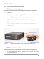
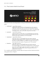
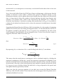
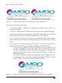
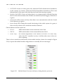
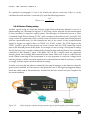
G E T T I N G S T A R T E D 1.3 The Control Unit’s Front Panel 1 2 3 4 The control unit is the same independently on the type of the Detection Head (free running or gated). 1. PHOTON OUT : output, SMA connector; a digital pulse is generated for each detected photon; the output is a NIM pulse, which means that it must be 50 Ω terminated and that the low logic level is 0 V and the high logic level is -‐‑800 mV. The falling edge of the pulse marks, with very low jitter, the photon arrival time; 2. VALID GATE : output, SMA connector; outputs the effective SPAD status: it is in the high logic level when the SPAD is ON or in the low logic level when the SPAD is OFF due to the hold-‐‑off. The output conforms to a LVTTL standard; 3. TRIGGER OUT : output, SMA connector; (USE ONLY when a GATED MODE detection head is attached) outputs the internal trigger reference signal used to periodically enable the SPAD. Normally disabled, it is enabled only when internal trigger is selected from the user interface. The pulses are LVTTL standard; 4. TRIGGER IN : input, SMA connector; (USE ONLY when a GATED MODE detection head is attached) if an external trigger is needed, then the signal must be connected to this input. The external trigger signal can be positive or negative within the range from -‐‑2 V to +2.5 V and the internal comparator allows for a programmable threshold. For a complete understanding of module input and outputs and their absolute maximum ratings please refer to Chapter 4. Micro Photon Devices S.r.l. – Italy All Rights Reserved 4