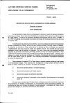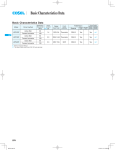
1
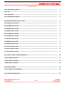
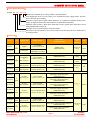
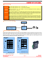
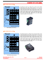
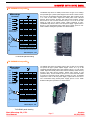
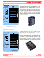
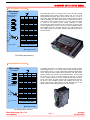
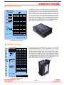
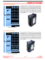
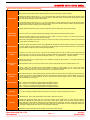
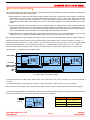
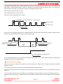
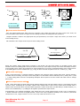
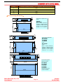
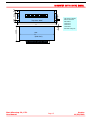
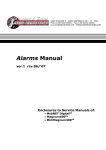
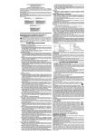
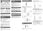
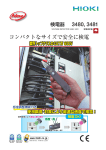
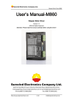
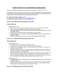
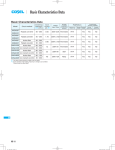
MICROSTEP MOTOR DRIVE MANUAL CONTENTS Drive Model Naming Rules ------------------------------------------------------------------------------- 2 Drive list --------------------------------------------------------------------------------------------------- 2 Drive Operation ------------------------------------------------------------------------------------------ 3 Drive Connection Diagram ------------------------------------------------------------------------------ 3 EA202D & MU-2H202D Drive Profile ------------------------------------------------------------------- 3 MX-2H304D Drive Profile ------------------------------------------------------------------------------- 4 MX-2H306D Drive Profile -------------------------------------------------------------------------------- 4 TX-2H504D Drive Profile --------------------------------------------------------------------------------- 5 TX-3H504D Drive Profile -------------------------------------------------------------------------------- 5 MZ-2H504A Drive Profile -------------------------------------------------------------------------------- 6 MZ-2H506A Drive Profile -------------------------------------------------------------------------------- 6 TZ-2H704A Drive Profile ---------------------------------------------------------------------------------- 7 TZ-3H504A Drive Profile ---------------------------------------------------------------------------------- 7 TZ-3H506A Drive Profile -------------------------------------------------------------------------------- 8 TD-2H611A Drive Profile --------------------------------------------------------------------------------- 8 TD-3H511A Drive Profile --------------------------------------------------------------------------------- 9 TD-3H522A Drive Profile --------------------------------------------------------------------------------- 9 Drive Main Function Setting & Operation --------------------------------------------------------------- 10 Control Signal Interface ----------------------------------------------------------------------------------- 11 2-phase Motors Interface --------------------------------------------------------------------------------- 12 3-phase Motor Interface --------------------------------------------------------------------------------- 13 DIP Switch Setting ---------------------------------------------------------------------------------------- 13 Driver Output Current Setting --------------------------------------------------------------------------- 13 Drive Mounting Dimensions ------------------------------------------------------------------------------ 14 Start Microstep CO., LTD. User Manual Page 1 Version 11/30/2010 MICROSTEP MOTOR DRIVE MANUAL 【Drive Model Naming】 Example: M X - 2 H 3 0 4 D / d k Special series: example, dk for carving machine, GM series without; Power Supply type: D for dc power supply, A for 50/60Hz AC power supply (All AC- powered driver can use DC power supply); Maximum or typical power supply voltage divided by 10: example for Maximum DC40V power supply. AC supply for virtual value, detail reference to specification instructions; Maximum output current: 2-phase drive mark Peak current, 3-phase drive mark value current (RMS), Sample Peak current 3.0A; Drive type: 2H for two phase hybrid, 3H for three-phase; Drive Series code: MU and EA for micro-drives, MX and TX for min-drive, MZ TZ for medium-drive, TD for large-drives; 【Drive list】 Model Phase Segment Step Supply Power Output Current & TYPICAL VALUE 2/4/8/16 0.4-1.7A (Max) 4 ranks, accuracy 0.4A MU-2H202D 2/5/10/20/40 1.7A customization, non-adjust MX-2H304D 22 ranks Max micostep 200 Max step 40000 0.2A-3.0A (Max) 16 ranks, accuracy 0.2A 28 ranks Max step 60000 0.4A-5.0A (Max) 16 ranks, accuracy 0.4A DC(24-40)V, Typical value DC24/ DC 32V POWER OVER 150W 28 ranks Max step 60000 0.3A-5.2A(effective value) 16 ranks, accuracy 0.3A DC(24-36)V, Typical value DC24 / DC 32V POWER OVER 150W EA202D MX-2H306D 2 phase 2 phase TX-2H504D TX-3H504D 3 phase MZ-2H504A MZ-2H506A 22 ranks Max step 40000 0.4A-5.0A (Max) 16 ranks, accuracy 0.4A 28 ranks Max step 60000 0.5A-7.5A (Max) 16 ranks, accuracy 0.5A 3 phase 28 ranks Max step 60000 0.3A-5.2A (effective value) 16 ranks, accuracy 0.3A 2 phase 28 ranks Max step 60000 0.4A-6.0A (Max) 16 ranks, accuracy 0.4A 2 phase TZ-2H704A TZ-3H504A TZ-3H506A TD-2H611A TD-3H511A TD-3H522A 3 phase 28 ranks Max step 60000 Start Microstep CO., LTD. User Manual 0.3A-5.2A (effective value) 16 ranks, accuracy 0.3A Dimensions (mm) Size Weight(kg) POWER: DC24V POWER OVER 50W 100× 60× 19 0.17 kg Micro DC(24-40)V, Typical value DC24、32V POWER OVER 100W 123× 76× 31 0.27 kg Min DC(40-60)V, Typical value DC50V POWER OVER 150W 123× 76× 38 0.35 kg Min Thicken 123× 76× 31 0.27 kg Min 157× 99× 56 0.7kg Medium 177× 122× 75 1.1kg large AC(24-45)V, Typical value AC40V DC(40-60)V, Typical value DC50V POWER OVER 200W AC(40-60)V, Typical value AC50V DC(60-80)V, Typical value DC70V POWER OVER 250W AC(24-45)V, Typical value AC40V DC(40-60)V, Typical value DC50V POWER OVER 250W AC(24-45)V, Typical valuAC40V DC(40-60)V, Typical value DC50V POWER OVER 200W AC(40-60)V, Typical value AC50V DC(60-80)V, Typical value DC70V POWER OVER 250W AC(70-140)V, Typical value AC80V & AC110V POWER OVER 500W AC(70-140)V, Typical value AC80V & AC110V POWER OVER 500W AC(180-240)V, Typical value AC220V POWER OVER 600W Page 2 Version 11/30/2010 MICROSTEP MOTOR DRIVE MANUAL 【Drive Operation】 Input power DC power supply, voltage error -15% - +15%, ripple ≤ 5%; AC power supply, voltage error -30% - +10%, frequency of 50/60Hz Working condition Operating temperature: -10C~45C; Humidity: 10~85% non-condensing; Non-corrosive, explosive, gas or liquid conductive; no metal dust. Installation Drive should be installed in a well ventilated and protective electrical control cabinet. Please keep the air channel for the cooling fan drive. If the heat dissipated by drive shell, drive should be fixed in the bigger and thick metal plate or cabinet, contact surface should be smooth or coated with heat conductive silicon grease. Fixing cooling fan beside drive is also a better heat dissipation method. Connection Control line should be used to shielded cable and separated with the power line and electrical lines. NOTE: Strictly prohibited tinning on the ending of control line and connection terminals! Otherwise it would cause heat damage to the terminal, generally use lead sheeting or direct access to the drive. PE terminal is ground protection side. In the case of non-isolated powered, drives and motors must be ground protection ( Recommended powered by isolation transformer) 【 Driver Connection diagram】 Power MS Series step motor drive Controller part: CNC system, Controller, PLC, Computer I/O board 【EA202D and MU-2H202D Drive profile】 EA202D and MU-2H202D step drives are micro-drives; the size and installation are same. The main type used to drive 42 type or small 57 type 2-phase stepper motor. Both of them power supply are DC24, output Max phase current (peak) are 1.7A. The difference is as follows: 1. The number of segments is different (see below); 2. EA202D could set four gear phase current by DIP switch, while the MU-2H202D can only output a fixed current which the user could not adjust, user could customize the current before the instructions, and otherwise the factory default value is 1.7A. Microstep Microstep EA202D MU-2H202D A B B motor current setting sw3,4 current 00 0.4A 01 0.8A 1.2A 10 11 1.7A CP+ CPDIR+ DIRA A B B + 1 0 DIRA sw1 2 3 4 CPDIR+ 1 0 sw 1 2 3 4 CP+ microstep setting sw1,2 steps 00 400 01 800 10 1600 11 3200 microstep setting sw1,2,3 steps 000 400 001 1000 010 2000 011 4000 100 8000 101 110 n/a 111 Out current 1.7A DC(12-24)V/2A + - - Power status DC (12-24) V/2A Power status Microstep Co., Ltd. EA202D panel drawing Start Microstep CO., LTD. User Manual Microstep Co., Ltd. MU-2H202D panel drawing Page 3 Version 11/30/2010 MICROSTEP MOTOR DRIVE MANUAL 【MX-2H304D Drive profile】 Microstep 1 0 MX-2H304D CP+ CPDIR+ DIREN+ EN- status1(green) status2(red) A – A sw1-5 steps sw1-5 steps 00000 CP/DIR 10000 10000 00001 400 10001 12000 00010 800 10010 12800 00011 1000 10011 14400 00100 1600 10100 20000 00101 1800 10101 25600 00110 2000 10110 40000 00111 3000 10111 01000 3200 11000 01001 3600 11001 n/a 01010 4000 11010 01011 5000 11011 01100 6000 11100 01101 6400 11101 01110 7200 11110 test 01111 8000 11111 cw/ccw sw6=0 not low power sw6=1 auto low power sw7=1.6 A sw8=0.8 A sw9=0.4 A sw10=0.2 A sum of sw7-10 to set current 3.0 Amps Maximum(Peak) MX-2H304D step drives are mainly used to drive 57 type 2-phase hybrid stepper motor which current is below 3A. It is up to 22 segments and Max 40000 steps. Step could be set by 1 to 5 bit of DIP switch. Signal and doubt pulse mode. Self-test function, Phase memory function, auto half current function. Output max current is 3.0A. Current could be set bye 7 to 10 bit of the DIP switch (it could set 16 speeds current, setting resolution is 0.3A). MX-2H304D step drives is 24V to 49V DC power supply. Typical value is DC 24V or 32V. Recommend using switch power supply, power is over 100W. Relation setting and operation is as shown below. 西 B 红 y – B 柿 y 西 y+ 红 y DC (24-40V) – 柿 see user’s guide for more information. y西 Start Microstep Co., Ltd. 红 柿 MX-2H304D panel drawing y 【MX-2H306D Drive profile】 Microstep 1 0 MX-2H306D CP+ CPDIR+ DIREN+ EN- status1(green) status2(red) A – A 西 B 红 y – B 柿 y 西 y+ 红 y DC (40-60V) – 柿 y西 红 柿 y sw1-5 steps sw1-5 steps 00000 CP/DIR 10000 10000 00001 400 10001 12000 00010 800 10010 12800 00011 1000 10011 14400 00100 1600 10100 20000 00101 1800 10101 25600 00110 2000 10110 40000 00111 3000 10111 01000 3200 11000 01001 3600 11001 n/a 01010 4000 11010 01011 5000 11011 01100 6000 11100 01101 6400 11101 01110 7200 11110 test 01111 8000 11111 cw/ccw sw6=0 not low power sw6=1 auto low power sw7=1.6 A sw8=0.8 A sw9=0.4 A sw10=0.2 A sum of sw7-10 to set current 3.0 Amps Maximum(Peak) MX-2H306D step drives are mainly used to drive high voltage 57 type 2-phase hybrid stepper motor which current is below 3A. It is up to 22 segments and Max 40000 steps. Step could be set by 1 to 5 bit of DIP switch. Signal and doubt pulse mode. Self-test function, Phase memory function, auto half current function. Output max current is 3.0A. Current could be set bye 7 to 10 bit of the DIP switch (it could set 16 speeds current, setting resolution is 0.3A). MX-2H306D step drives is 40V to 60V DC power supply. Typical value is DC 40V or 50V. Recommend using switch power supply, power is over 150W. Relation setting and operation is as shown below. see user’s guide for more information. Start Microstep Co., Ltd. MX-2H306D panel drawing Start Microstep CO., LTD. User Manual Page 4 Version 11/30/2010 MICROSTEP MOTOR DRIVE MANUAL 【TX-2H504D Drive profile】 Microstep 1 0 TX-2H504D CP+ CPDIR+ DIREN+ EN- status1 (green) status2 (red) A – A 西 B 红 y – B 柿 y 西 y+ 红 y DC (24-40V) – 柿 y西 红 柿 sw1-5 steps sw1-5 steps 00000 CP/DIR 10000 5000 00001 200 10001 6000 00010 400 10010 6400 00011 500 10011 7200 00100 600 10100 8000 00101 800 10101 10000 00110 1000 10110 12000 00111 1200 10111 12800 01000 1600 11000 20000 01001 2000 11001 24000 01010 2400 11010 30000 01011 2500 11011 40000 01100 3000 11100 60000 n/a 01101 3200 11101 01110 3600 11110 test 01111 4000 11111 cw/ccw sw6=0 not low power sw6=1 auto low power sw7=2.6 A sw8=1.3 A sw9=0.7 A sw10=0.4 A sum of sw7-10 to set current 5.0 Amps Maximum(Peak) TX-2H504D step drives are mainly used to drive 57 type or low voltage low speed 86 type 2-phase hybrid stepper motor which current is below 5A. It is up to 28 segments and Max 60000 steps. Step could be set by 1 to 5 bit of DIP switch. Signal and doubt pulse mode. Self-test function, Phase memory function, auto half current function. Output max current is 5.0A. Current could be set bye 7 to 10 bit of the DIP switch (it could set 16 speeds current, setting resolution is 0.3A). TX-2H504D step drives is 24V to 40V DC power supply. Typical value is DC 24V or 32V. Recommend using switch power supply, power is over 150W. Relation setting and operation is as shown below. see user’s guide for more information. Microstep Co., Ltd. TX-2H504D panel drawing y 【TX-3H504D Drive profile】 Microstep 1 0 TX-3H504D CP+ CPDIR+ DIREN+ EN- status1(green) status2(red) U V y W y + DC ( 24-36V ) y – 西 红 柿 y sw1-5 steps sw1-5 steps 00000 CP/DIR 10000 5000 00001 200 10001 6000 00010 400 10010 6400 00011 500 10011 7200 00100 600 10100 8000 00101 800 10101 10000 00110 1000 10110 12000 00111 1200 10111 12800 01000 1600 11000 20000 01001 2000 11001 24000 01010 2400 11010 30000 01011 2500 11011 40000 01100 3000 11100 60000 n/a 01101 3200 11101 01110 3600 11110 test 01111 4000 11111 cw/ccw sw6=0 not low power sw6=1 auto low power sw7=2.8 A sw8=1.4 A sw9=0.7 A sw10=0.3 A sum of sw7-10 to set current 5.2 Amps Maximum(RMS) TX-3H504D step drives are mainly used to drive 57 type or low voltage low speed 86 type 3-phase hybrid stepper motor. It is up to 28 segments and Max 60000 steps. Step could be set by 1 to 5 bit of DIP switch. Signal and doubt pulse mode. Self-test function, Phase memory function, auto half current function. Output max current is 5.2A (effective value). Current could be set bye 7 to 10 bit of the DIP switch (it could set 16 speeds current, setting resolution is 0.3A). TX-3H504D step drives is 24V to 36V DC power supply. Typical value is DC 24V or 32V. Recommend using switch power supply, power is over 150W. Relation setting and operation is as shown below. see user’s guide for more information. Microstep Co.,Ltd. TX-3H504D panel drawing Start Microstep CO., LTD. User Manual Page 5 Version 11/30/2010 MICROSTEP MOTOR DRIVE MANUAL 【MZ-2H504A Drive profile】 Microstep 1 0 MZ-2H504A status1(green) status2(red) sw1-5 steps sw1-5 steps 00000 CP/DIR 10000 10000 00001 400 10001 12000 00010 800 10010 12800 00011 1000 10011 14400 00100 1600 10100 20000 00101 1800 10101 25600 00110 2000 10110 40000 00111 3000 10111 01000 3200 11000 01001 3600 11001 n/a 01010 4000 11010 01011 5000 11011 01100 6000 11100 01101 6400 11101 01110 7200 11110 test 01111 8000 11111 cw/ccw sw6=0 not low power sw6=1 auto low power sw7=2.6 A sw8=1.3 A sw9=0.7 A sw10=0.4 A sum of sw7-10 to set current 5.0 Amps Maximum(Peak) CP+ CPDIR+ DIREN+ EN- A – A 西 B 红 y – B 柿 y 西 y~ 红 AC ( 24-40V ) ~ 柿 MZ-2H504A step drives are mainly used to drive 86 type 2-phase hybrid stepper motor which current is below 5A. It is up to 22 segments and Max 40000 steps. Step could be set by 1 to 5 bit of DIP switch. Signal and doubt pulse mode. Self-test function, Phase memory function, auto half current function. Output max current is 5.0A (Peak). Current could be set bye 7 to 10 bit of the DIP switch (it could set 16 speeds current, setting resolution is 0.4A). MZ-2H504A step drives can drive by DC or AC power. AC input is 24V to 45V. Typical value is AC 40V. DC power is also available, positive and negative can access. DC input is 40V to 60V. Typical value is DC 50V. Supply power is over 200W. Relation setting and operation is as shown below. see user’s guide for more nformation y Microstep Co.,Ltd. MZ-2H504A panel drawing 【MZ-2H506A Drive profile】 Microstep 1 0 MZ-2H506A status1(green) status2(red) CP+ CPDIR+ DIREN+ EN- A – A 西 B 红 y – B 柿 y 西 y~ 红 AC ( 40-60V ) ~ 柿 sw1-5 steps sw1-5 steps 00000 CP/DIR 10000 10000 00001 400 10001 12000 00010 800 10010 12800 00011 1000 10011 14400 00100 1600 10100 20000 00101 1800 10101 25600 00110 2000 10110 40000 00111 3000 10111 01000 3200 11000 01001 3600 11001 n/a 01010 4000 11010 01011 5000 11011 01100 6000 11100 01101 6400 11101 01110 7200 11110 test 01111 8000 11111 cw/ccw sw6=0 not low power sw6=1 auto low power sw7=2.6 A sw8=1.3 A sw9=0.7 A sw10=0.4 A sum of sw7-10 to set current 5.0 Amps Maximum(Peak) MZ-2H506A step drives are mainly used to drive 86 type 2-phase hybrid stepper motor which current is below 5A. It is up to 22 segments and Max 40000 steps. Step could be set by 1 to 5 bit of DIP switch. Signal and doubt pulse mode. Self-test function, Phase memory function, auto half current function. Output max current is 5.0A (Peak). Current could be set bye 7 to 10 bit of the DIP switch (it could set 16 speeds current, setting resolution is 0.4A). MZ-2H506A step drives can drive by DC or AC power. AC input is 40V to 60V. Typical value is AC 50V. DC power is also available, positive and negative can access. DC input is 60V to 80V. Typical value is DC 70V. Supply power is over 250W. Relation setting and operation is as shown below. see user’s guide for more information y Microstep Co.,Ltd. MZ-2H506A panel drawing Start Microstep CO., LTD. User Manual Page 6 Version 11/30/2010 MICROSTEP MOTOR DRIVE MANUAL 【TZ-2H704A Drive profile】 Microstep 1 0 TZ-2H704A status1(green) status2(red) sw1-5 steps sw1-5 steps 00000 CP/DIR 10000 5000 00001 200 10001 6000 00010 400 10010 6400 00011 500 10011 7200 00100 600 10100 8000 00101 800 10101 10000 00110 1000 10110 12000 00111 1200 10111 12800 01000 1600 11000 20000 01001 2000 11001 24000 01010 2400 11010 30000 01011 2500 11011 40000 01100 3000 11100 60000 n/a 01101 3200 11101 01110 3600 11110 test 01111 4000 11111 cw/ccw sw6=0 not low power sw6=1 auto low power sw7=4.0 A sw8=2.0 A sw9=1.0 A sw10=0.5 A sum of sw7-10 to set current 7.5 Amps Maximum(Peak) CP+ CPDIR+ DIREN+ EN- A – A 西 B 红 y – B 柿 y 西 y~ 红 AC ( 24-40V ) ~ 柿 TZ-2H704A step drives are mainly used to drive 86 type 2-phase hybrid stepper motor which current is below 7.5A. It is up to 28 segments and Max 60000 steps. Step could be set by 1 to 5 bit of DIP switch. Signal and doubt pulse mode. Self-test function, Phase memory function, auto half current function. Output max current is 7.5A (Peak). Current could be set bye 7 to 10 bit of the DIP switch (it could set 16 speeds current, setting resolution is 0.5A). TZ-2H704A step drives can drive by DC or AC power. AC input is 24V to 45V. Typical value is AC 40V. DC power is also available, positive and negative can access. DC input is 40V to 60V. Typical value is DC 50V. Supply power is over 250W. Relation setting and operation is as shown below. see user’s guide for more information y Microstep Co.,Ltd. TZ-2H704A panel drawing 【TZ-3H504A Drive profile】 Microstep 1 0 TZ-3H504A CP+ CPDIR+ DIREN+ EN- status1(green) status2(red) U V y W y ~ y~ AC ( 24-40V ) sw1-5 steps sw1-5 steps 00000 CP/DIR 10000 5000 00001 200 10001 6000 00010 400 10010 6400 00011 500 10011 7200 00100 600 10100 8000 00101 800 10101 10000 00110 1000 10110 12000 00111 1200 10111 12800 01000 1600 11000 20000 01001 2000 11001 24000 01010 2400 11010 30000 01011 2500 11011 40000 01100 3000 11100 60000 n/a 01101 3200 11101 01110 3600 11110 test 01111 4000 11111 cw/ccw sw6=0 not low power sw6=1 auto low power sw7=2.8 A sw8=1.4 A sw9=0.7 A sw10=0.3 A sum of sw7-10 to set current 5.2 Amps Maximum(RMS) TZ-3H504A step drives are mainly used to drive 86 type 3-phase hybrid stepper motor. It is up to 28 segments and Max 60000 steps. Step could be set by 1 to 5 bit of DIP switch. Signal and doubt pulse mode. Self-test function, Phase memory function, auto half current function. Output max current is 5.2A (effective value). Current could be set bye 7 to 10 bit of the DIP switch (it could set 16 speeds current, setting resolution is 0.3A). TZ-3H504A step drives can drive by DC or AC power. AC input is 24V to 45V. Typical value is AC 40V. DC power is also available, positive and negative can access. DC input is 40V to 60V. Typical value is DC 50V. Supply power is over 200W. Relation setting and operation is as shown below. see user’s guide for more information. Microstep Co.,Ltd. TZ-3H504A panel drawing Start Microstep CO., LTD. User Manual Page 7 Version 11/30/2010 MICROSTEP MOTOR DRIVE MANUAL 【TZ-3H506A Drive profile】 Microstep 1 0 TZ-3H506A CP+ sw1-5 steps sw1-5 steps 00000 CP/DIR 10000 5000 00001 200 10001 6000 00010 400 10010 6400 00011 500 10011 7200 00100 600 10100 8000 00101 800 10101 10000 00110 1000 10110 12000 00111 1200 10111 12800 01000 1600 11000 20000 01001 2000 11001 24000 01010 2400 11010 30000 01011 2500 11011 40000 01100 3000 11100 60000 n/a 01101 3200 11101 01110 3600 11110 test 01111 4000 11111 cw/ccw sw6=0 not low power sw6=1 auto low power sw7=2.8 A sw8=1.4 A sw9=0.7 A sw10=0.3 A sum of sw7-10 to set current 5.2 Amps Maximum(RMS) CPDIR+ DIREN+ EN- status1(green) status2(red) U V y W y ~ y~ AC ( 40-60V ) TZ-3H506A step drives are mainly used to drive 86 type 3-phase hybrid stepper motor. It is up to 28 segments and Max 60000 steps. Step could be set by 1 to 5 bit of DIP switch. Signal and doubt pulse mode. Self-test function, Phase memory function, auto half current function. Output max current is 5.2A (effective value). Current could be set bye 7 to 10 bit of the DIP switch (it could set 16 speeds current, setting resolution is 0.3A). TZ-3H506A step drives can drive by DC or AC power. AC input is 40V to 60V. Typical value is AC 50V. DC power is also available, positive and negative can access. DC input is 60V to 80V. Typical value is DC 70V. Supply power is over 250W. Relation setting and operation is as shown below. see user’s guide for more information. Microstep Co.,Ltd. TZ-3H506A panel drawing 【TD-2H611A Drive profile】 LED Microstep TD-2H611A CP+ CPDIR+ DIR- switchs definition: set before power-on off(1) on(0) EN+ ENNo Rdy LEDs definition: status1(green) status2(red) A A Vin definition: AC(80-110)V 50/60Hz B steps cp/dir 200 400 500 600 800 1000 1200 1600 2000 2400 2500 3000 3200 3600 4000 sw6=0 sw6=1 sw 1--5 10000 10001 10010 10011 10100 10101 10110 10111 11000 11001 11010 11011 11100 11101 11110 11111 steps 5000 6000 6400 7200 8000 10000 12000 12800 20000 24000 30000 40000 60000 n/a test cw/ccw TD-2H611A step drives are mainly used to drive 110 type 2-phase hybrid stepper motor which current is below 6A. It is up to 28 segments and Max 60000 steps. Step could be set by 1 to 5 bit of DIP switch. Signal and doubt pulse mode. Self-test function, Phase memory function, auto half current function. Output max current is 6.0A (Peak). Current could be set bye 7 to 10 bit of the DIP switch (it could set 16 speeds current, setting resolution is 0.4A). TD-2H611A step drives can drive by AC power. AC input is 70V to 140V. Typical value is AC 80V and AC 110V. Supply power is over 250W. Relation setting and operation is as shown below. not low power auto low power sw7=3.2A sw8=1.6A sw9=0.8A sw10=0.4A sum of sw7-10 to set current 6.0 Amps Maximum(Peak) B ~ Vin ~ sw 1--5 00000 00001 00010 00011 00100 00101 00110 00111 01000 01001 01010 01011 01100 01101 01110 01111 See users guide for more information! Microstep Co., Ltd. TD-2H611A panel drawing Start Microstep CO., LTD. User Manual Page 8 Version 11/30/2010 MICROSTEP MOTOR DRIVE MANUAL 【TD-3H511A Drive profile】 LED Microstep TD-3H511A CP+ CPDIR+ DIR- switchs definition: set before power-on off(1) on(0) EN+ ENNo Rdy LEDs definition: status1(green) status2(red) U V Vin definition: AC(80-110)V 50/60Hz W steps cp/dir 200 400 500 600 800 1000 1200 1600 2000 2400 2500 3000 3200 3600 4000 sw6=0 sw6=1 sw 1--5 10000 10001 10010 10011 10100 10101 10110 10111 11000 11001 11010 11011 11100 11101 11110 11111 steps 5000 6000 6400 7200 8000 10000 12000 12800 20000 24000 30000 40000 60000 n/a test cw/ccw TD-3H511A step drives are mainly used to drive 110 type 3-phase hybrid stepper motor. It is up to 28 segments and Max 60000 steps. Step could be set by 1 to 5 bit of DIP switch. Signal and doubt pulse mode. Self-test function, Phase memory function, auto half current function. Output max current is 5.2A (effective value). Current could be set bye 7 to 10 bit of the DIP switch (it could set 16 speeds current, setting resolution is 0.3A). TD-3H511A step drives can drive by AC. AC input is 70V to 140V. Typical value is AC 80V and AC110V. Supply power is over 500W. Relation setting and operation is as shown below. not low power auto low power sw7=2.8A sw8=1.4A sw9=0.7A sw10=0.3A sum of sw7-10 to set current 5.2 Amps Maximum(RMS) n/a ~ Vin ~ sw 1--5 00000 00001 00010 00011 00100 00101 00110 00111 01000 01001 01010 01011 01100 01101 01110 01111 See users guide for more information! Microstep Co., Ltd. TD-3H511A panel drawing 【TD-3H522A Drive profile】 LED Microstep TD-3H522A CP+ CPDIR+ DIR- switchs definition: set before power-on off(1) on(0) EN+ ENNo Rdy LEDs definition: status1(green) status2(red) U V Vin definition: AC220V 50/60Hz W steps cp/dir 200 400 500 600 800 1000 1200 1600 2000 2400 2500 3000 3200 3600 4000 sw6=0 sw6=1 sw 1--5 10000 10001 10010 10011 10100 10101 10110 10111 11000 11001 11010 11011 11100 11101 11110 11111 steps 5000 6000 6400 7200 8000 10000 12000 12800 20000 24000 30000 40000 60000 n/a test cw/ccw TD-3H522A step drives are mainly used to drive 110 type 3-phase hybrid stepper motor. It is up to 28 segments and Max 60000 steps. Step could be set by 1 to 5 bit of DIP switch. Signal and doubt pulse mode. Self-test function, Phase memory function, auto half current function. Output max current is 5.2A (effective value). Current could be set bye 7 to 10 bit of the DIP switch (it could set 16 speeds current, setting resolution is 0.3A). TD-3H522A step drives can drive by AC. AC input is 180V to 2400V. Typical value is AC 200V and AC220V. Supply power is over 600W. Relation setting and operation is as shown below. not low power auto low power sw7=2.8A sw8=1.4A sw9=0.7A sw10=0.3A sum of sw7-10 to set current 5.2 Amps Maximum(RMS) n/a ~ Vin ~ sw 1--5 00000 00001 00010 00011 00100 00101 00110 00111 01000 01001 01010 01011 01100 01101 01110 01111 See users guide for more information! Microstep Co., Ltd. TD-3H522A panel drawing Start Microstep CO., LTD. User Manual Page 9 Version 11/30/2010 MICROSTEP MOTOR DRIVE MANUAL 【Drive Main Function Setting & Operation】 EA202D 和 MU-2H202D step drives could be set by 1, 2 bit of DIP switch. EA202D could set 4 segments and MU-2H202D set 5 segments. More detail operation please reference the plant drawing, N/A is invalid condition. Segment Step M series step drives could be set by 1, 2, 3, 4, 5 bit of DIP switch. M series step drives could be set 22 segments (step) and max 40000 steps. Drive should be set before switch on otherwise setting is invalid. More detail operation please reference the plant drawing, N/A is invalid condition. T series step drives could be set by 1, 2, 3, 4, 5 bit of DIP switch. M series step drives could be set 28 segments (step) and max 60000 steps. Drive should be set before connect to the power otherwise setting is invalid. More detail operation please reference the plant drawing, N/A is invalid condition. EA202D and MU-2H202D step drives only have signal pulse mode. No doubt pulse mode, without setting. Signal/doubt pulse setting M and T series step drives have signal pulse mode and doubt pulse mode. Setting 1-5 bit DIP switch as 00000, switch on the driver. After 2 to 5 second the green light twinkling, switch off and then setting the steps and Rpm. Doubt pulse setting: Setting 1-5 bit DIP switch as 11111. Switch on the power. After 2 to 5 second the green light twinkling, switch off and then setting the steps and Rpm. Notes: Once signal/doubt pulse setting as previous, only when the pulse is change otherwise unnecessary second setting whether drives is switched on or off. Self-test function All the step drives have self-test function except EA202D and MU-2H202D. Self-test function: Setting 1-5 bit DIP switch as 11110, switch on the driver. After 2 to 5 second the step drive began in a lower frequency drive motor. This function is used to detect the drives properly without pulse signal setting. Auto half current function All models have auto half current function. Drive will automatically enter the half current state after the pulse stop 2 to 5 seconds. The current of the motor is only half of the normally working in order to reduce power consumption and protect the motor. You can also choose without this function (EA202D and MU-2H202D type drive excluded). For the M and T-type drives, the sixth bits DIP switch setting this function: 0 - no such function, 1 - have this function. EA202D step drive can set 4-speed output current available by setting the DIP switches 3, 4 bit. Data could be read directly from the table. Output current setting MU-2H202D step drive can not set the output current. Factory-configured by the user, the default value is 1.7A. M and T series have 16-speed output current available by setting the DIP switches 7, 8, 9, 10 bit. Drive output sine-wave current to the motor. Current is peak value for 2-phase motor and effective value for 3-phase motor. Total output current is equal to the sum of current when the 7, 8, 9, 10bits switch point 1. Phase memory function Signal interface Electrical Interface Power Interface Indicator Installation The drive power-off at a certain phase position, and phase position of next powering up is different, then the motor will chatter look. In order to eliminate chattering of motor, Drive should memory the power off phase position. This function is very important in a certain industries. M and T series have this function, Memory time is infinite. EA202D and MU-2H202D step drive have none. CP + and CP- are as a step pulse signal positive and negative, DIR + and DIR- are direction level signal positive and negative terminal, EN + and EN- are To enable level signal positive and negative terminal, CW +, and CW- are forward pulse signal positive and negative terminal, CCW + and CCW-is backward pulse signal positive and negative terminal. A, A-, B, B- for connecting 2-phase hybrid motor. Reverse One side of the two phase lines, can reverse the motor; U, V, W for connecting 3-phase hybrid motor. Reverse any two lines, which can make the motor reverse. Different drives have different power requirements, More details reference relations description in the 【Introduction】. Note: All AC-powered drive can be able to driving by DC power. 【drive list】 & EA202D and MU-2H202D drives only have the power indicator. Other models drive has green and red indicator, respectively indicating the operational status of the drive: Green light, red light off for the normal working condition; green light flash, red light off for setting the single and double pulse; green flash, red light is illegal state; green light, red light flashing for the over current protection state; green light, red double flash for the over-voltage protection; the green light, red light flashes three times for over-temperature protected. Considering the heat elimination, drive installation should keep cooling channels Start Microstep CO., LTD. User Manual Page 10 Version 11/30/2010 MICROSTEP MOTOR DRIVE MANUAL 【Driver control signal interface】 Drive is retransmitted weak signal of the computer controller system into strong signal which could be accepted by stepper motor. Control system output three type of driving signal. 1. Step Pulse signal CP: This is the most important signal, because the principle of stepper drive control system is converts the pulse signal of the control system into angular displacement of the stepper motor. Or, Drive receive pulse signal CP, then motor rotate a certain step angle, CP frequency is positive proportional to stepper motor speed. Amount of CP pulse determines the rotation angle of the stepper motor. Thus, control system regulates motor speed and position by CP pulse signal. 2. Direction level signal DIR: This signal defines the motor rotation direction. For example, Motor clockwise rotation in high level signal and anticlockwise rotation in low level signal. This reversing method is called signal pulse mode. In addition, there is a double pulse mode. Drive receive two line pulse signal (marked as CW and CCW). Motor rotates forward in CW pulse signal; motor rotates backward in CCW pulse signal. User setting signal and double pulse by DIP switch. 3. Enable signal EN: No Connection EN signal default effective status, then Drive work. Connect EN signal circuit, drive stop working. Torque free condition (equivalent to FREE signal of SH series drive), this signal is optional signal. Our driver inner adopt optocoupler isolating input-signal in order to keep the normal communication and avoid mutual interference between the control system and drive. Three-way signal have same inner interface circuit. Common connection is as follows: ① Common-anode mode :Connect CP +, DIR + and EN + as common-anode with +5V external system; Connect pulse signal with CP-; Direction level signal with DIR-; Connect enable signal with EN-; ② Common-cathode mode: Connect CP -, DIR - and EN - as common-cathode with GND external system; Connect pulse signal with CP+; Direction level signal with DIR+; Connect enable signal with EN+; ③ Differential mode: Connect directly. Drive inner CP+/ CW+ 270 270 270 CP-/ CWDIR+/CCW+ DIR-/CCWEN+ ENDrive input signal inner interface diagram If the drive input signal is voltage signal, voltage range: 3.6V ≤ high level ≤ 5.5V;-5.5V ≤ low level≤ 0.3V, the most commonly is TTL level. If the drive input signal is current signal, current range: 7mA ≤ high current ≤ 18mA;-18mA ≤ low current ≤ 0.2mA. Either voltage or current signals, convert into optocoupler input current, in order to transport signal (reference above diagram), If the voltage signal amplitude exceed standard numerical, user should add limiting resistance on external CP and DIR terminal, to ensure 7-18mA current to the drive’s inner optocoupler, reference below diagram. R External Signal Amplitude Limiting Resistance (R) 5V 12V 24V Drive inner 270 Start Microstep CO., LTD. User Manual Page 11 NON 1.0K 2.0K Version 11/30/2010 MICROSTEP MOTOR DRIVE MANUAL Pulse signal control stepper motor running. Stepper motor rotates a certain angle when the effective edge of the stepper motor pulse signal is coming. Effective edge is mean: the moment of pulse signal current from small to large, or the moment of pulse-level from low to high, or the moment of inner drive optocoupler from stop to open. Pulse frequency requires less than 200 KHz; Pulse width requirement of not less than 2μS. Pulse drive current requirements for the 7-18mA Pulse width≥2μS,Pulse frequency≤200KHz Arbitrary duty ratio Pulse-level =high Pulse-level =low Effective edge Be sure the motor stopped, and then convert its rotational direction. The DIR signal could change over 5μS after ending of the last effective edge in forward direction and does not delay next pulse edge. Last CP pulse in forward direction Negative pulses method ≥5μ S ≥0μ S First CP pulse in next direction Negative pulses method Reverse signal DIR work this moment If driver adopt double pulse CW / CCW mode, the first pulse of next direction (such as CCW) could be effective 5μs delay the last pulse(CW) effective edge of forward direction. 【2-phase motor Interface】 2-phase drive could be connected with 2-phase or 4-phase hybrid motor. Different motor winding have different connection methods, as follows: For the two-phase four wire motor, the drive can be connected directly (see below Part I); For the four-phase six-wire motor, the middle tap of the two lines are vacant, the other four wires are connected with drive (see Figure II); For the four-phase five wire motor, the windings are not independent, the motor and drive can not be connected (see Figure III); Eight four-phase eight wire motor, usually connected each two winding in parallel, and then connect with the drive (see below Part IV). Start Microstep CO., LTD. User Manual Page 12 Version 11/30/2010 MICROSTEP MOTOR DRIVE MANUAL A+ d- A+ A+ a Vacant AB- A- c- a- c+ b + B+ B+ VacantB- Motor can connect with drive directly, middle tap of the two Motor connect with drive directly + + AB+ d lines are vacant This Motor can connect motor could not connect with drive because windings are not independent bB- with drive in parallel 【3-phase motor Interface】 Drive and 3-phase hybrid motor adopt three-wire connection. Drive output three phase sine wave current to the motor, the current is effective value nominal. Two types of motor winding connection: the triangle and star (see below): Triangle Connection: Common used, high-speed and good performance, but requires a large drive current (1.73 times of the motor winding current). Star connection: Drive output current is equal to motor winding current U U I=i I=1.73i Drive input current I Drive output current I V Winding phase current V Winding phase current W W NOTE: Our company motors adopt triangle connection in the internal, only three lines leading out (excluding ground). Motor nominal current is not winding phase current, but the line current (i.e., drive output current). User set the drive output current to motor nominal current. If drive equip with motor of other manufacturers, user need to understand meaning of the nominal current. If the winding phase current is nominal value (e.g., 2.8A), the drive current be set phase current of 1.73 times (e.g., 4.8A). 【DIP switch settings】 M and T series drives have a 10-bit DIP switch for setting the step (segment), single / double pulse mode, self-test operation, automatic half current setting, the output current setting and so on. DIP switch 2 state is defined by 0 and 1, namely: ON = 0, OFF = 1. Detail setting please refers the corresponding description and the panel of the drive models. DIP switch must be settings before power. 【Driver output current setting】 M and T series drives have 16 speed output current optional, setting by the 4 bit DIP switches (sw7-10). Drive output sine wave current to motor. Considering the user habit, 2-phase motor nominal value is peak current; 3-phase motor nominal value is effective value current. Each bit of 4 bit DIP switches represents a certain current value (see table below) in enable condition (= 1) and”0” in non-enabled state (= 0). Adding four bit together represents drive output current. General Settings is (For example, MZ-2H504A, 3.6A): starting from 7 bit, seventh represent 2.6A, as 3.6A> 2.6A, so seventh set to 1. Remain 3.6A-2.6A=1.0A is not set. Eighth represent 1.3A, as 1.0A<1.3A, so eighth non-enabled, set to 0. And so on, the last bit should be set to 1011, output current is 2.6+0+0.7+0.4=3.7A, in this case the error is 0.1A. Start Microstep CO., LTD. User Manual Page 13 Version 11/30/2010 MICROSTEP MOTOR DRIVE MANUAL Switch Current in Enable condition(=1)(Example: Max Current is 5.0A) 7 2.6A 8 1.3A 9 0.7A 10 0.4A 5.0 This structure applies follow mode: 10.5 19.0 【Drive Mounting dimensions】 EA202D MU-2H202D Shell is heat conduction structure. Suggest vertical installation. Coated thermal grease on the contact surface if it is uneven. 6.5 84.0 H 17.0 5.4 8 28.5 60.0 5.0 100.0 This structure applies MX and TX series: MX-2H304D TX-2H504D TX-3H504D H=31 122.0 5.2 105. 0 This structure applies MZ and TZ series: MZ-2H504A MZ-2H506A TZ-2H704A TZ-3H504A TZ-3H506A With Self-cooling fan, Vertical installation 157.0 142.0 10 99.0 Shell is heat conduction structure. Suggest vertical installation. Coated thermal grease on the contact s ur fac e if it is uneven. 10 7.0 56.0 21.0 37.0 76.0 5.1 MX-2H306D H=38 Start Microstep CO., LTD. User Manual Page 14 Version 11/30/2010 9 6. 0 11 10.0 51.0 12.0 MICROSTEP MOTOR DRIVE MANUAL (Top View: label) 120.0 2.0 178. 0 This structure applies MD and TD series: MD-2H611A TD-2H611A TD-3H511A TD-3H522A With Self-cooling fan 158. 0 1 5 (Side View) Start Microstep CO., LTD. User Manual Page 15 Version 11/30/2010 MICROSTEP MOTOR DRIVE MANUAL Start Microstep CO., LTD. User Manual Page 16 Version 11/30/2010