1
UM0250
Getting started
1.4.3
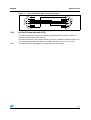
Cross-wired serial cable connection diagram
6
1
5
2
4
3
3
4
2
5
1
9
8
7
8
9
7
6
DB9 female
DB9 female
Figure 2.
In-Circuit Communication (ICC)
The 10-pin connector must be connected to a programming tool in order to program or
erase the microcontroller Flash memory.
For further information, please refer to both the ICC Protocol Reference Manual and the ST7
Flash Programming Reference Manual, available online from http://www.st.com/mcu
Note:
The USB cable must be plugged in to supply the board with voltage.
5/12