1
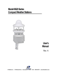
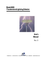
Model 6500
Thunderstorm/Lightning Detector
User’s
Manual
Rev. D
All Weather Inc. • 1165 National Drive • Sacramento, CA 95834 • USA • 800.824.5873 • www.allweatherinc.com
Copyright © 2011, All Weather, Inc.
All Rights Reserved. The information contained herein is proprietary and is provided solely for the purpose of
allowing customers to operate and/or service All Weather, Inc. manufactured equipment and is not to be released,
reproduced, or used for any other purpose without written permission of All Weather, Inc.
Throughout this manual, trademarked names might be used. Rather than put a trademark (™) symbol in every
occurrence of a trademarked name, we state herein that we are using the names only in an editorial fashion and to
the benefit of the trademark owner, and with no intention of infringement. All Weather, Inc. and the All Weather,
Inc. logo are trademarks of All Weather, Inc.
Disclaimer
The information and specifications described in this manual are subject to change without notice.
Latest Manual Version
For the latest version of this manual, see the Product Manuals page under Reference on our web site at
www.allweatherinc.com/.
All Weather, Inc.
1165 National Drive
Sacramento, CA 95834
Tel.: (916) 928-1000
Fax: (916) 928-1165
Contact Customer Service
•
Phone support is available from 8:00am - 4:30pm PT, Monday through Friday. Call 916-928-1000 and ask for
“Service.”
•
Online support is available by filling out a request at www.allweatherinc.com/customer/support.html
•
E-mail your support request to [email protected]
6500 Thunderstorm/Lightning Detector
User's Manual
TABLE OF CONTENTS
1. OVERVIEW .........................................................................................................................1
1.1 Lightning Detection Antenna .................................................................................................... 1
1.2 Lightning Detection Data Processor .......................................................................................... 1
2. THEORY OF OPERATION .................................................................................................2
2.1 Lightning Detection ................................................................................................................... 2
2.2 Data Processing ......................................................................................................................... 2
2.3 Data Reporting........................................................................................................................... 2
3. DATA FORMAT...................................................................................................................4
3.1 Sensor Polling............................................................................................................................ 4
3.2 Sensor Output Format................................................................................................................ 4
3.2.1 Sensor Mode .................................................................................................................... 5
3.2.2 Strike Rate........................................................................................................................ 5
3.2.3 Lightning Description ...................................................................................................... 5
3.2.4 Lightning Location........................................................................................................... 6
3.2.5 Status Word...................................................................................................................... 6
3.2.6 Sensor Status .................................................................................................................... 6
3.2.7 Error Codes ...................................................................................................................... 7
3.2.8 Sensor Mode .................................................................................................................... 8
3.2.9 Noise Triggers .................................................................................................................. 8
3.2.10 Strike Test Rate ................................................................................................................ 8
3.2.11 Software Version ............................................................................................................. 8
3.2.12 Error Flag ......................................................................................................................... 8
3.2.13 Checksum ......................................................................................................................... 8
4. INSTALLATION & CHECKOUT ........................................................................................ 11
4.1 RFI/EMI Precautions ............................................................................................................... 11
4.2 Sensor Installation ................................................................................................................... 12
4.3 Checkout .................................................................................................................................. 15
5. DCP DISPLAY SCREENS ................................................................................................ 16
5.1 Data Screens ............................................................................................................................ 16
5.1.1 Lightning Sensor Pg. 1 ................................................................................................... 16
5.1.2 Lightning Sensor Pg. 2 ................................................................................................... 16
5.1.3 Lightning Sensor Pg. 3 ................................................................................................... 17
5.1.4 Lightning Sensor Pg. 4 ................................................................................................... 17
5.2 Status Screens .......................................................................................................................... 17
5.2.1 Lightning Sensor Pg. 5 ................................................................................................... 18
5.2.2 Lightning Sensor Pg. 6 and Pg. 7 ................................................................................... 18
5.2.3 Lightning Sensor Pg. 8 ................................................................................................... 18
6. ERROR MESSAGES AND TROUBLESHOOTING ........................................................... 19
6.1 Processor LEDs ....................................................................................................................... 22
6500 Thunderstorm/Lightning Detector
User's Manual
7. MAINTENANCE................................................................................................................ 23
7.1 Periodic Maintenance Schedule .............................................................................................. 23
7.1.1 Monthly Maintenance ................................................................................................... 23
7.1.2 Triannual Maintenance .................................................................................................. 23
7.1.3 Annual Maintenance ..................................................................................................... 23
7.2 Maintenance Procedures ......................................................................................................... 23
7.2.1 Equipment Required ...................................................................................................... 23
8. SPECIFICATIONS ............................................................................................................ 24
9. WARRANTY ..................................................................................................................... 25
6500 Thunderstorm/Lightning Detector
User's Manual
1. OVERVIEW
The Model 6500 Thunderstorm/Lightning Detector detects electrical discharges associated with
thunderstorms within a 200 nautical mile (nm) radius of the system. The Thunderstorm/Lightning
Detector is a passive sensor that monitors electromagnetic signals with a receiving antenna. There is
no transmitter, and so no harmful transmissions.
The entire package (consisting of an antenna mounted to a 28" × 31" ground plane, and a processor
and interface board housed in a NEMA 4X enclosure) mounts simply to a 2½" pipe (2.875" O.D.)
using two U-bolts.
1.1 LIGHTNING DETECTION ANTENNA
The Thunderstorm/Lightning Detector’s lightning detection antenna is a combined crossed-loop and
sense antenna, which can correlate the electric and magnetic signatures of lightning strikes better than
other systems because of its patented sense channel technology. The antenna has been designed to
help filter out pulsed noise from sources other than lightning discharges. The antenna detects the
electrical and magnetic fields generated by cloud-to-ground lightning, and sends the resulting
“discharge signals” to the processor.
1.2 LIGHTNING DETECTION DATA PROCESSOR
The Thunderstorm/Lightning Detector ‘s lightning detection processor houses the data acquisition
circuitry, along with circuitry to process lightning strike data and communicate with the AWOS Data
Collection Platform (DCP). Communication with the DCP is via an RS-485 link. The lightning
detection processor digitizes, analyzes, and converts the discharge signals into range and bearing data,
then stores the data in memory.
The DCP polls the lightning detection sensor every two seconds via an RS-485 link. When polled, the
sensor transmits a data package consisting of strike data and status information. When errors are
detected, a command can be sent from the DCP requesting a complete error log from the sensor. This
error log provides greater detail on the nature and severity of the error.
1
6500 Thunderstorm/Lightning Detector
User's Manual
2. THEORY OF OPERATION
2.1 LIGHTNING DETECTION
The Model 6500’s antenna is a combined crossed-loop and sense antenna, which can correlate the
electric and magnetic signatures of lightning strikes better than other systems because of its patented
sense channel technology. The antenna has been designed to help filter out pulsed noise from sources
other than atmospheric electrical discharges.
The antenna detects the electrical and magnetic fields generated by intra-cloud, inter-cloud, or cloudto-ground electrical discharges that occur within a 200 nautical mile radius of the antenna, and sends
the resulting “discharge signals” to the processor. The processor digitizes, analyzes, and converts the
discharge signals into range and bearing data, then stores the data in memory.
2.2 DATA PROCESSING
The Model 6500’s processor is housed inside the sensor enclosure along with the Interface Board. The
processor includes data acquisition circuitry and circuitry to process strike data. The Interface Board
provides a data buffer and handles communication with the Data Collection Platform (DCP).
The DCP polls the sensor every five seconds via an RS-485 link. When polled, the sensor transmits a
data package consisting of strike data and status information. When errors are detected, the errors are
recorded in an error log, and the most recent error is displayed on the lightning sensor status screen at
the DCP (see Section 5.1).
2.3 DATA REPORTING
The Model 6500 detects the presence of a lightning event within 200 nautical miles from the point of
installation, and reports any of that activity occurring within a 30 nautical mile radius of the point of
installation. The sensor detects and locates thunderstorms and provides the data as part of the standard
AWOS message.
1. Range and Direction
Reports thunderstorms/lightning within a 30 nautical mile radius from the installation point.
Direction is expressed in compass octants for distances from 10 to 30 nautical miles.
2. Resolution
The location of thunderstorm is reported to within ±1 nautical mile from actual location of the
thunderstorm/ lightning detector.
3. Accuracy from Installation Point
Within 10 nautical miles of installation:
Detection: 90% of all thunderstorms
Location: does not exceed 3 nautical miles
Between 10 nautical miles and 30 nautical miles of installation:
Detection: 80% of all thunderstorms
Location: does not exceed 6 nautical miles
2
6500 Thunderstorm/Lightning Detector
User's Manual
4. False Reports
Not more than 2%.
5. Reporting
Updates AWOS information once each minute.
3
6500 Thunderstorm/Lightning Detector
User's Manual
3. DATA FORMAT
The Model 6500 Thunderstorm/Lightning Detector interfaces to the DCP via the RS-485 network.
RS-485 communication is set to 4800 bps, no parity, one stop bit.
3.1 SENSOR POLLING
The DCP polls the Thunderstorm/Lightning Detector every five seconds using the DCP poll command
shown below.
LTNG00\r\n
3.2 SENSOR OUTPUT FORMAT
The data received from the Thunderstorm/Lightning Detector are displayed on the DCP’s LCD
display as they are received. The lightning data shown at the Central Display Platform (CDP) are
updated once per minute.
The sensor output is formatted as follows.
=s rrrr ts/vsts ltg_dsnt status e crc <CR><LF>
The data fields are space-delimited. The field values should be interpreted as follows.
s
rrrr
ts/vsts
ltg_dsnt
status
E
CRC
<CR>
<LF>
Sensor Mode
The strike rate in counts per minute in normal mode
Lightning Description
Lightning Location
Sensor operational status word
Error Flag
This provides a checksum value for data validation
Carriage Return (hexadecimal value 0D)
Line Feed (hexadecimal value 0A)
The sample poll response below is a normal poll response when there is no lightning detected by the
LTX sensor.
=A 0 _ _ [email protected] 0 042C1
The sample poll response shown below is a sample poll response with 102 counts per minute of
lightning reported from 5 to 10 nautical miles away in the Northeast, Southeast, South, Southwest, and
Northwest quadrants. Table 1 explains each of the fields, which are identified in the poll response and
in the table headings using color coding.
=A 102 VCTS LTG_DSNT_NE_SE_S_SW_NW [email protected] ] 0A380
4
6500 Thunderstorm/Lightning Detector
User's Manual
Table 1. Sensor Output Field Descriptions
Sensor Mode
A
E
Normal
Self-Test
Strike Rate
counts/min
LTX Description
LTX Location
_
None
(> 10 miles)
TS
Thunderstorm
(< 5 n miles)
VCTS
Very Close
Thunderstorm
(5–10 n miles)
LTG_DSNT
Distant
Lightning
(10–30 n
miles)
3.2.1 Sensor Mode
=
_
NE
E
SE
S
SW
W
NW
N
ALQDS
None
Northeast
East
Southeast
South
Southwest
West
Northwest
North
All Quadrants
Status
Error Flag
Checksum
See Error
Codes
Indicates if there
has been an error
CRC16
checksum;
see
Checksum
A 102 VCTS LTG_DSNT_NE_SE_S_SW_NW [email protected]
] 0A380
For normal sensor operation, the sensor should always be reporting an A for the mode. The sensor
should not be operating in any other mode.
3.2.2 Strike Rate
=A
102 VCTS LTG_DSNT_NE_SE_S_SW_NW [email protected]
] 0A380
This is the number of lightning strikes detected within the full 200 nautical mile radius of the sensor
during the previous one minute. The example shows the sensor reporting 102 lightning strikes during
that 1-minute period.
3.2.3 Lightning Description
=A 0
_ [email protected] 0 042C1
The lightning description indicates the distance of the lightning strikes that have been detected. The
underscore “_” is used to show that there were no lightning strikes within 10 miles of the sensor. This
is shown in the first example.
If the lightning strikes are within 5 nautical miles of the sensor, TS is indicated in this location of the
poll response. This means that there is a thunderstorm at the sensor location.
=A 102
VCTS LTG_DSNT_NE_SE_S_SW_NW [email protected]
]
If the lightning strikes are from 5 to 10 nautical miles from the sensor, VCTS is indicated in this
location of the poll response. This reports that there is a thunderstorm in the vicinity of the LTX
sensor. This is demonstrated in the example poll response.
=A 102 VCTS
LTG_DSNT_NE_SE_S_SW_NW [email protected]
]
If the lightning strikes are from 10 to 30 nautical miles from the sensor LTG_DSNT is indicated in
this location of the poll response. This is showing that there is lightning distant from the sensor, but
still detectable as lightning.
5
6500 Thunderstorm/Lightning Detector
User's Manual
3.2.4 Lightning Location
=A 102 VCTS LTG_DSNT_
NE_SE_S_SW_NW [email protected]
]
This field indicates the location of the detected lightning strikes. T he normal cardinal points with
their standard abbreviations (N for North, SE for Southeast, etc.) are used in this location of the poll
response. If there are lightning strikes detected at multiple directions, they will each be listed with an
underscore “_” separating them. T he example poll response shows lightning from the Northeast,
Southeast, South, Southwest, and Northwest.
3.2.5 Status Word
=A 102 VCTS LTG_DSNT_NE_SE_S_SW_NW
[email protected]
]
The sensor status is made up of 6 sections. The breakout of the status word is shown below.
[email protected]
Table 2 explains each of the fields, which are identified in the example and in the table headings using
color coding. Also note that each section of the status word is preceded by an indicator letter (S for
status, E for error codes, etc.).
Table 2. Status Word Fields
Status
P
OK
R
Recoverable
error
F
Fatal error
Error
Code
See
Error
Codes
3.2.6 Sensor Status
Mode
Config
Heading
Buffer
Reset
A
Normal
Operating
Should
be G
Should
be @
Normally
X
Normally
R
E
Self-Test
=A 102 VCTS LTG_DSNT_NE_SE_S_SW_NW
Noise
Triggers
Number
of
triggers
in Noise
Mode
Strike
Test
Rate
Strike
Test
Mode
result
[email protected]
Software
Version
Version of
installed
software
] 0A380
The first value in the status word is the sensor status. The sensor status is preceded by a S. The sensor
status value is a P for normal operation. If there has been an error and the sensor recovered from that
error, the status is R. If the sensor has had an error that it cannot recover from, the status is F.
6
6500 Thunderstorm/Lightning Detector
3.2.7 Error Codes
User's Manual
[email protected]
=A 102 VCTS LTG_DSNT_NE_SE_S_SW_NW SP
0A380
]
The error codes are represented by two numerical digits preceded by an E. The following table shows
all the error codes with their probable causes.
Table 3. Error Codes and Probable Causes
Number
Error
Probable Cause
00
No Error
Normal Operation
01
Processor Fault
Main processor
05–08
Processor Fault
Main processor memory
09–12
Processor Fault
DSP processor memory
14, 15
Processor Fault
DSP processor
16
Antenna Fault
Antenna or antenna wiring
17
Processor Fault
No test strikes, antenna in noisy location, or
faulty antenna
18
Processor Fault
Invalid test strikes, antenna in noisy location,
or faulty antenna
19
Processor Fault
Main Processor or Antenna in noisy location
20
Configuration Changed
Antenna location (top/bottom, determined by
processor wiring) changed since system was
last powered up.
21
Processor Fault
Main processor
22
Invalid XYZ Input
N/A
23
Invalid Heading Reference
N/A
24
MIC Key Stuck
Mic key (inhibit line) has been asserted for at
least 60 seconds
25–34
Processor Fault
Main processor
35
Processor Fault
Main or DSP processor
36
Processor Fault
Main or DSP processor
40
Processor Fault
Main processor
41
Processor Fault
Main or DSP processor
42
Processor Fault
Main processor
43
Invalid request
Poll command was not received properly
Serial Communication
General communication errors including
wrong baud rate, excessive noise, etc.
44–49
7
6500 Thunderstorm/Lightning Detector
3.2.8 Sensor Mode
User's Manual
[email protected]
=A 102 VCTS LTG_DSNT_NE_SE_S_SW_NW SPE00
]
The sensor mode is preceded by an M. There are five parts to the sensor mode section of the status
word. The first digit represents the sensor mode. This should always be an A for normal operation.
The test mode is not used.
The second digit is the sensor configuration. This should always be a G. The third digit is the sensor
heading flag. This should always be a @. The forth digit is the buffer flag. This is a B if the buffer
has been cleared and an X if the clear message has not been received. The fifth digit is the reset flag.
This can either be an X or a R.
3.2.9 Noise Triggers
N00000R0000VB1.03
=A 102 VCTS LTG_DSNT_NE_SE_S_SW_NW SPE00MAG@XR
] 0A380
The noise trigger count is preceded by an N. The noise trigger section of the status word is for the
number of triggers detected when noise mode is on. This is a five digit number that should always be
00000 while the sensor is in normal operation.
3.2.10 Strike Test Rate
=A 102 VCTS LTG_DSNT_NE_SE_S_SW_NW SPE00MAG@XRN00000
R0000VB1.03
]
The strike test rate is preceded by an R. The four digit number in the strike test rate section of the
status word is the number of strikes detected per minute while the sensor is in the Strike Test mode.
While the sensor is in normal operation, this should be 0000.
3.2.11 Software Version
=A 102 VCTS LTG_DSNT_NE_SE_S_SW_NW SPE00MAG@XRN00000R0000
VB1.03
]
The software version of the sensor is preceded by a V. In the example shown the software version is
B1.03. There are two separate software programs in the sensor. The second is in the serial interface
board inside the sensor. The second software version is not displayed in the poll response.
3.2.12 Error Flag
=A 102 VCTS LTG_DSNT_NE_SE_S_SW_NW [email protected] ]
0A380
This is only a status indicator that there was an error. This will normally be a 0. Any other character
than a 0 indicates that an error has occurred. Refer to the error section of the status word for the actual
error that occurred.
3.2.13 Checksum
=A 102 VCTS LTG_DSNT_NE_SE_S_SW_NW [email protected] ] 0
A380
The last four text digits of the poll response is the checksum of the poll response. This allows the
polling computer to verify that the data message was received properly. The checksum is calculated
using the CRC16 method. A sample C program for calculating this CRC is shown below.
8
6500 Thunderstorm/Lightning Detector
User's Manual
/***************************************************************
CRC routine
USE:
crc = crc16(buffer, length, initial_value)
where:
crc is the returned value,
buffer is the data buffer to compute a crc
length is the number of bytes in buffer to process
initial_value is the results of previous crc calculations
that will allow the buffer crc to be computed in
stages if necessary. If this is not necessary,
then set initial_value to 0.
******************************************************************/
unsigned int crc16(char *string, unsigned int length, unsigned int ival)
/* buffer address to compute a crc */
/* number of characters to process */
/* initial value of crc
*/
{
static unsigned int crc;
/*
CRC values for crc16 routine
*/
static unsigned int
crc_vals[] =
{
0x0000,0xc0c1,0xc181,0x0140,0xc301,0x03c0,0x0280,0xc241,
0xc601,0x06c0,0x0780,0xc741,0x0500,0xc5c1,0xc481,0x0440,
0xcc01,0x0cc0,0x0d80,0xcd41,0x0f00,0xcfc1,0xce81,0x0e40,
0x0a00,0xcac1,0xcb81,0x0b40,0xc901,0x09c0,0x0880,0xc841,
0xd801,0x18c0,0x1980,0xd941,0x1b00,0xdbc1,0xda81,0x1a40,
0x1e00,0xdec1,0xdf81,0x1f40,0xdd01,0x1dc0,0x1c80,0xdc41,
0x1400,0xd4c1,0xd581,0x1540,0xd701,0x17c0,0x1680,0xd641,
0xd201,0x12c0,0x1380,0xd341,0x1100,0xd1c1,0xd081,0x1040,
0xf001,0x30c0,0x3180,0xf141,0x3300,0xf3c1,0xf281,0x3240,
0x3600,0xf6c1,0xf781,0x3740,0xf501,0x35c0,0x3480,0xf441,
0x3c00,0xfcc1,0xfd81,0x3d40,0xff01,0x3fc0,0x3e80,0xfe41,
0xfa01,0x3ac0,0x3b80,0xfb41,0x3900,0xf9c1,0xf881,0x3840,
0x2800,0xe8c1,0xe981,0x2940,0xeb01,0x2bc0,0x2a80,0xea41,
0xee01,0x2ec0,0x2f80,0xef41,0x2d00,0xedc1,0xec81,0x2c40,
0xe401,0x24c0,0x2580,0xe541,0x2700,0xe7c1,0xe681,0x2640,
0x2200,0xe2c1,0xe381,0x2340,0xe101,0x21c0,0x2080,0xe041,
0xa001,0x60c0,0x6180,0xa141,0x6300,0xa3c1,0xa281,0x6240,
0x6600,0xa6c1,0xa781,0x6740,0xa501,0x65c0,0x6480,0xa441,
0x6c00,0xacc1,0xad81,0x6d40,0xaf01,0x6fc0,0x6e80,0xae41,
0xaa01,0x6ac0,0x6b80,0xab41,0x6900,0xa9c1,0xa881,0x6840,
0x7800,0xb8c1,0xb981,0x7940,0xbb01,0x7bc0,0x7a80,0xba41,
0xbe01,0x7ec0,0x7f80,0xbf41,0x7d00,0xbdc1,0xbc81,0x7c40,
0xb401,0x74c0,0x7580,0xb541,0x7700,0xb7c1,0xb681,0x7640,
0x7200,0xb2c1,0xb381,0x7340,0xb101,0x71c0,0x7080,0xb041,
0x5000,0x90c1,0x9181,0x5140,0x9301,0x53c0,0x5280,0x9241,
0x9601,0x56c0,0x5780,0x9741,0x5500,0x95c1,0x9481,0x5440,
0x9c01,0x5cc0,0x5d80,0x9d41,0x5f00,0x9fc1,0x9e81,0x5e40,
0x5a00,0x9ac1,0x9b81,0x5b40,0x9901,0x59c0,0x5880,0x9841,
9
6500 Thunderstorm/Lightning Detector
User's Manual
0x8801,0x48c0,0x4980,0x8941,0x4b00,0x8bc1,0x8a81,0x4a40,
0x4e00,0x8ec1,0x8f81,0x4f40,0x8d01,0x4dc0,0x4c80,0x8c41,
0x4400,0x84c1,0x8581,0x4540,0x8701,0x47c0,0x4680,0x8641,
0x8201,0x42c0,0x4380,0x8341,0x4100,0x81c1,0x8081,0x4040};
crc = ival;
while(length--)
crc = crc_vals[(*string++ ^ crc) & 0xff] ^
((crc >> 8) & 0xff);
return crc;
}
/* end crc16 routine */
10
6500 Thunderstorm/Lightning Detector
User's Manual
4. INSTALLATION & CHECKOUT
NOTE
Installation and checkout of the Model 6500 Thunderstorm/ Lightning
Detector may only be performed by qualified personnel trained in the
theory of operation of the Model 6500 Thunderstorm/Lightning
Detector, site preparation requirements, maintenance theory of the
Automated Weather Observing System (AWOS), and interface and
operation functions of the AWOS Data Collection Platform.
The Thunderstorm/Lightning Detector package (consisting of an antenna mounted to a 28" x 32"
ground plane and a processor housed in a NEMA 4X enclosure) mounts to a 2½" pipe (2.875" O.D.)
using two U-bolts. A section of 2.5" (64 mm) I.D. standard galvanized steel pipe can be used as a mast
with no drawbacks or special adaptation. Refer to the site preparation instructions and applicable
drawings for foundation, grounding, conduit, and junction box installation details.
C AUT ION
T he T hunders torm/L ightning Detec tor’s ground plane extends well beyond
the edges of the s ens or enc los ure. B e aware of this hazard when working
around the s ens or.
4.1 RFI/EMI PRECAUTIONS
The Model 6500 Thunderstorm/ Lightning Detector’s antenna is sensitive to static charges, so care
must be taken to ensure that the antenna and ground plane are as far removed as possible from
composite materials (e.g., plastic materials or fiberglass), since these materials have a tendency to
build up a static charge.
The sensor should be mounted as far as possible from devices that emit high levels of radio-frequency
interference (RFI) and electromagnetic interference (EMI), such as VHF and UHF radios, RF modems,
fluorescent lamps, and ballasts, air conditioner and heater blowers, as well as any current-carrying
cables. Pay attention to these general clearance guidelines.
•
•
•
•
•
•
Strobe lamps and power supplies — 5 ft. (1.5 m)
Fluorescent lamps and ballasts — 5 ft. (1.5 m)
Air conditioners and heater blowers — 5 ft. (1.5 m)
Telephone antennas — 4 ft. (1.2 m)
VHF communication antennas — 1 ft. (0.3 m)
Any current-carrying cable — 2 ft. (0.6 m)
In addition to the above restrictions, certain site installations may have to be scrutinized more carefully from an RFI/EMI perspective. Finding locations to mount the ground plane and antenna that will
minimize interference from RFI/EMI sources can be enhanced by the use of standard RFI measuring
equipment. The recommended equipment for monitoring the proposed installation area is a typical
spectrum analyzer with a broadband conical antenna. The spectrum analyzer should be set up to scan
11
6500 Thunderstorm/Lightning Detector
User's Manual
the frequencies of concern (100-500 MHz) for the typical VHF and UHF radio links near the
installation. Once it has been determined that there is significant interference, it is imperative that the
lightning sensor be moved to a location as far from the interfering device as possible. Under no
circumstances should the lightning sensor antenna and ground plane be placed within one foot of
either a VHF or UHF transmitting antenna.
4.2 SENSOR INSTALLATION
After installing the mast, conduit, and junction box, follow the instructions below for assembling and
installing the sensor.
1. If the signal and power cables have not already been installed between the signal and power
distribution boxes and the sensor pad, pull the required lengths of cable through conduit to the
junction boxes at the sensor pad.
2. (See Figure 1). The mounting bracket attaches to the underside of the 6500 enclosure with four
bolts. Position the bracket against the underside of the enclosure so that the mounting holes in
the bracket and enclosure align.
Figure 1. Mounting Bracket Installation
3. Apply RTV 162 to the threads of the four 5/16" hex mounting bolts.
4. Fasten the bracket to the enclosure with the four 5/16" hex bolts, flat washers, and lock
washers.
5. Tighten the bolts.
6. Set the sensor package (antenna, ground plane, enclosure, and bracket) on the mast, and fasten
loosely with two U-bolts, lock washers, and flat washers as shown in Figure 2.
12
6500 Thunderstorm/Lightning Detector
User's Manual
Figure 2. Sensor Package Mounting
7. Align the antenna to magnetic north by holding a straightedge compass against the ground
plane (with the compass's North index oriented in the same direction as the N on the ground
plane) and turning the entire sensor package until the compass indicates North.
8. Tighten the two U-bolts.
9. Open the sensor enclosure by loosening the four countersunk bolts shown in Figure 3. Do not
remove the six bolts holding the ground plane to the enclosure lid.
Figure 3. Opening the Sensor Enclosure
10. The sensor enclosure lid is equipped with hinged bolts (see Figure 4) to allow the box to be
opened with the ground plane attached. Grasp both sides of the ground plane and lift straight
up as far as possible (about 3"), then tilt the ground plane and lid over carefully to gain access
to the enclosure interior. When fully open, the ground plane will rest against the side of the
enclosure.
13
6500 Thunderstorm/Lightning Detector
User's Manual
Figure 4. Enclosure Hinges
11. Route the signal and power cables from their junction boxes through flex conduit to the sensor.
12. Connect the signal wires to the interface board inside the enclosure (Figure 5) according to
Table 4.
13. Connect the incoming AC power wires to the AC interface board inside the enclosure (Figure
5) according to Table 4.
14. Close the enclosure lid and tighten the four countersunk bolts.
15. Fasten a ground wire between the ground cable installed during site preparation and the ground
clamp on the underside of the enclosure (see Figure 1).
Figure 5. Interface Board
14
6500 Thunderstorm/Lightning Detector
User's Manual
Table 4. Lightning Detector Signal and Power Wiring
Interface Board TB1
Pin
Function
Color
DCP TB4
Pin
4
RS485 (+)
WHITE
1
5
RS485 (-)
BLACK
2
6
GROUND
RED
7
AC Interface Board TB1
Pin
Function
Color
1
HOT
BLACK
2
NEUTRAL
WHITE
3
GROUND
GREEN
TB4
Interface
Board
TB1
7 (GND)
7
RED
6
5
DCP
BLACK
4
WHITE
2 (RS485 (-))
3
1 (RS485 (+))
2
1
AC Interface
Board
TB1
1
HOT (BLACK)
2
NEUT (WHITE)
3
GND (GREEN)
AC POWER
4.3 CHECKOUT
To verify the sensor is working properly, power the sensor and DCP up and verify that, after one
minute of operation, data is reported from the sensor. (Bear in mind that, in the absence of lightning in
the measuring area, the data screens will report no strikes.) Check the status screens (described in the
next section) and verify that no errors are reported.
15
6500 Thunderstorm/Lightning Detector
User's Manual
5. DCP DISPLAY SCREENS
The lightning data generated by the Model 6500 Thunderstorm/Lightning Detector is available for
viewing on the DCP’s LCD display. These data are updated once per minute, and are shown on four
consecutive data screens immediately following the ADC Vref screen (Screen 27). Four status screens
follow the data screens.
To view the data and status screens, scroll to the first lightning data screen using the * and # keys on
the keypad as explained in the DCP User's Manual (to move down (to a higher numbered screen),
press the # key. To move up (to a lower numbered screen), press the * key). The contents of the
screens are explained below.
If the sensor is not working, offline, or not communicating with the DCP, the message "Sensor Not
Reporting" will be displayed on the first five screens (Pages 1–5), and
"MMMMMMMMMMMMMM" will be shown on the following two screens (Pages 6 and 7).
5.1 DATA SCREENS
Four separate screens report lightning data. The first three screens show strikes detected within
different distance ranges (<10 nautical miles, 10–20 nautical miles, and >20 nautical miles). When a
strike is detected, the data screens will show the direction of the strike by octant (N, S, NW, SE, etc.).
When strikes are detected in several directions, they will all be shown, separated from one another by
underscores. The fourth data screen shows the strike rate in number of strikes per minute.
5.1.1 Lightning Sensor Pg. 1
The first data screen reports any detected lightning strikes within 10 nautical miles of the installation
site.
If the strikes are within 0–5 nautical miles, the direction will be preceded by “TS” (thunderstorm).
This will be voiced in the AWOS voice output as “Thunderstorm at the airport.”
If the strikes are within 5–10 nautical miles, the direction will be preceded by “VCTS” (very close
thunderstorm). This will be voiced in the AWOS voice output as “Thunderstorm in the vicinity.”
If no strikes are detected, the message “No Strikes < 10 mi” will be displayed.
This screen is updated every minute.
Lightning
VCTS_E_SE_S
Sensor
Pg1
This example indicates strikes have been detected between 5–10 nautical miles of the installation site
to the East, Southeast, and South.
5.1.2 Lightning Sensor Pg. 2
The second data screen reports any detected lightning strikes between 10–30 nautical miles of the
installation site. This will be voiced in the AWOS voice output as “Lightning distant,” followed by the
direction of the strikes.
16
6500 Thunderstorm/Lightning Detector
User's Manual
If no strikes are detected, the message "No Strikes > 10 mi" will be displayed.
If the data string exceeds the LCD’s capacity (20 characters), the data will be continued on the next
screen (Lightning Sensor Pg. 3).
This screen is updated every minute.
Lightning
LTG_DSNT_S
Sensor
Pg2
This example indicates strikes have been detected between 10-30 miles of the installation site to the
South.
5.1.3 Lightning Sensor Pg. 3
The third data screen displays data continued from the previous screen when the amount of data for
the 10-30 mile range exceeds the LCD's 20-character capacity. If the data does not exceed 20 characters, this screen is a duplicate of Lightning Sensor Pg. 2.
Lightning
LTG_DSNT_S
Sensor
Pg3
This example shows the same data as the preceding screen, since the current data for the 10-30 mile
range does not exceed the LCD's capacity.
5.1.4 Lightning Sensor Pg. 4
The fourth data screen reports the number of strikes detected within the full measuring area (200
nautical mile radius of the installation site) during the previous one minute. The value is reported in
strikes per minute.
If no strikes were detected, the message “Strike Rate none” will be displayed.
This screen is updated every minute.
Lightning
Strike Rate 15/min
Sensor
Pg4
This example indicates 15 lightning strikes were detected within the measuring area during the
previous minute.
5.2 STATUS SCREENS
Four status screens follow the four lightning data screens. The first status screen shows the sensor's
current operating mode. The next two screens display the two most recent errors detected by the
sensor's self-tests. The final screen shows CRC errors and timeouts detected since power-up.
17
6500 Thunderstorm/Lightning Detector
User's Manual
5.2.1 Lightning Sensor Pg. 5
This screen shows the current operating mode of the sensor. This should always read "Normal
Weather Data", unless the sensor fails or is disconnected, in which case it will read "Sensor Not
Reporting".
Lightning
Sensor
Normal Weather Data
Pg5
5.2.2 Lightning Sensor Pg. 6 and Pg. 7
These two screens show the most recent status message received from the lightning sensor. The
format of the status message is explained in Error! Reference source not found., and the error codes
(indicated by the two-digit number immediately following "E") are listed in Table 5. Due to the length
of the message, it is split between two screens.
Lightning
Sensor
SPE00MAG@XXN00000
Pg6
Lightning
R0000VB1.03
Pg7
Sensor
The example shown above is decoded as follows.
SP
E00
MA
G
@
XX
N00000
R0000
VB1.03
Sensor status=OK
No errors
Normal Weather Data mode
Configuration=normal
Heading flag=normal
No clear message received from CDP; no reset
Noise mode OFF
Strike test mode OFF
Software version B1.03
5.2.3 Lightning Sensor Pg. 8
The final lightning sensor status screen shows the number of CRC errors and timeouts detected since
the sensor was powered up.
LTNG00
0/ 0
CRC
Err/Touts
The above example shows that no CRC errors and no timeouts have been recorded since the sensor
was last powered up.
18
6500 Thunderstorm/Lightning Detector
User's Manual
6. ERROR MESSAGES AND TROUBLESHOOTING
The Model 6500 continuously runs a series of self-tests to check sensor operation and returns error
messages when a fault is detected. The most recent status message is displayed on two status screens
viewable at the DCP (Lightning Sensor Pg. 6 and Lightning Sensor Pg. 7), as explained above. Any
detected errors are identified by "E" and a two-digit number ("E00" during normal operation) on the
first status screen. Table 5 lists all the possible error codes, along with the probable cause of the fault
and possible corrective action. In many cases, a persistent error will require returning the sensor to All
Weather Inc. for service.
For monitoring communications between the DCP and the sensor, a third status screen (Lightning
Sensor Pg. 8) displays a record of communications errors since the sensor was powered up.
Table 5. Model 6500 Thunderstorm/Lightning Detector Error Codes
ERROR
PROBABLE CAUSE
CORRECTIVE ACTION
ERROR 01. Processor Fault.
Main processor
Continued operation is not possible.
Contact Field Service.
ERROR 05. Processor Fault.
Main processor memory
Continued operation is not possible.
Contact Field Service.
ERROR 06. Processor Fault.
Main processor memory
Continued operation is not possible.
Contact Field Service.
ERROR 07. Processor Fault.
Main processor memory
Continued operation is not possible.
Contact Field Service.
ERROR 08. Processor Fault.
Main processor memory
Continued operation is not possible.
Contact Field Service.
ERROR 09. Processor Fault.
DSP processor memory
Continued operation is not possible.
Contact Field Service.
ERROR 10. Processor Fault.
DSP processor memory
Continued operation is not possible.
Contact Field Service.
ERROR 11. Processor Fault.
DSP processor memory
Continued operation is not possible.
Contact Field Service.
ERROR 12. Processor Fault.
DSP processor memory
Continued operation is not possible.
Contact Field Service.
ERROR 14. Processor Fault.
DSP processor
Continued operation is not possible.
Contact Field Service.
ERROR 15. Processor Fault.
DSP processor
Continued operation is not possible.
Contact Field Service.
ERROR 16. Antenna Fault.
Antenna or antenna wiring
Weather mapping is inhibited.
a. Check antenna wiring for opens and shorts.
b. Contact Field Service.
19
6500 Thunderstorm/Lightning Detector
User's Manual
Table 5. Model 6500 Thunderstorm/Lightning Detector Error Codes
ERROR
PROBABLE CAUSE
CORRECTIVE ACTION
ERROR 17. Processor Fault.
No test strikes, antenna in
noisy location, or faulty
antenna
Weather mapping is inhibited.
a. Check antenna wiring for opens and shorts.
b. Fault will clear automatically if interference
subsides.
c. Contact Field Service.
ERROR 18. Processor Fault.
Invalid test strikes, antenna in
noisy location, or faulty
antenna
Weather mapping is inhibited.
a. Check antenna wiring for opens and shorts.
b. Fault will clear automatically if interference
subsides.
c. Contact Field Service.
ERROR 19. Processor Fault.
Main Processor or Antenna in
noisy location
Weather mapping is inhibited.
a. Fault will clear automatically if interference
subsides.
b. Contact Field Service.
ERROR 20. Configuration
Changed.
Antenna location (top/bottom,
determined by processor
wiring) changed since system
was last powered up.
This may occur the first time the system is powered
on in a new installation. Power the sensor off and
back on again. If the error persists, contact Field
Service.
ERROR 21. Processor Fault.
Main processor
Continued operation is not possible.
Contact Field Service.
ERROR 22. Invalid XYZ Input.
n/a
n/a
ERROR 23. Invalid Heading Ref.
n/a
n/a
ERROR 24. MIC KEY STUCK.
Mic key (inhibit line) has been
asserted for at least 60
seconds
Weather mapping is inhibited.
a. Contact Field Service.
ERROR 25 - 34. Processor
Fault.
Main processor
Continued operation is not possible.
Contact Field Service.
ERROR 35. Processor Fault.
Main or DSP processor
Continued operation is not possible.
Contact Field Service.
ERROR 36. Processor Fault.
Main or DSP processor
Continued operation is not possible.
Contact Field Service.
ERROR 40. Processor Fault.
Main processor
Continued operation is not possible.
Contact Field Service.
ERROR 41. Processor Fault.
Main or DSP processor
Continued operation is not possible.
Contact Field Service.
ERROR 42. Processor Fault.
Main processor
Continued operation is not possible.
Contact Field Service.
20
6500 Thunderstorm/Lightning Detector
User's Manual
Table 5. Model 6500 Thunderstorm/Lightning Detector Error Codes
ERROR
PROBABLE CAUSE
CORRECTIVE ACTION
ERROR 43. Invalid request.
DCP
Message error will clear once processed
a. Excessive noise on communication lines,
check wiring.
b. If error occurs frequently, contact Field
Service
ERROR 44 - 49. Serial
Communication.
DCP
Message error will clear once processed
a. Improper baud rate from DCP.
b. Excessive noise on communication lines,
check wiring.
c. If error occurs frequently, contact Field
Service.
ERROR 50. Illegal Serial
Heading Value.
DCP
Message error will clear once processed
a. Excessive noise on communication lines,
check wiring.
b. If error occurs frequently, contact Field
Service.
ERROR 51. Invalid Message.
DCP
Message error will clear once processed
a. Excessive noise on communication lines,
check wiring.
b. If error occurs frequently, contact Field
Service.
ERROR 52. Invalid Antenna
Change Request.
DCP
Message error will clear once processed
a. A request was received to change the
antenna mount to a location that does not
match the configuration jumpers. Request is
ignored.
b. If error occurs frequently, contact Field
Service.
ERROR 53 - 54.
Communications Buffer
Overload.
DCP
Message error will clear once processed
a. Excessive noise on communication lines,
check wiring.
b. If error occurs frequently, contact Field
Service.
21
6500 Thunderstorm/Lightning Detector
User's Manual
6.1 PROCESSOR LEDS
The processor (housed within the enclosure) is equipped with a series of LEDs on its front panel (see
Figure 6) that can be used to monitor certain basic functions. Table 6 explains how to interpret the
LEDs.
Figure 6. Processor Front Panel LEDs
Table 6. Processor LED Functions
COMMUNICATION
LED
NORMAL OPERATION
FAILED OPERATION
DSP
1
ON
OFF
6
Toggles ON/OFF
when strike detected
Does not toggle ON/OFF
when strike detected
7
OFF
ON
8
Toggles ON/OFF
once per second
Stays ON or OFF
(does not toggle)
TX
Reserved for future use
Reserved for future use
RX
Reserved for future use
Reserved for future use
TX
ON
(pulses when TX occurs) *
Stays OFF or ON
(does not pulse)
RX
ON
(pulses when RX occurs) *
Stays OFF or ON
(does not pulse)
MAIN
SERIAL
* Serial communication occurs every 2 seconds, causing LEDs to pulse rapidly. Due to transmission speed, LEDs may
appear not to change conditions during TX/RX operation.
22
6500 Thunderstorm/Lightning Detector
User's Manual
7. MAINTENANCE
The routine maintenance described in this chapter must be performed according to the schedule
presented in Section 7.1 using the maintenance procedures described in Section 7.2.
7.1 PERIODIC MAINTENANCE SCHEDULE
Periodic maintenance procedures for the 7150 Series Digital Barometers are divided into three
categories within the maintenance cycle — monthly, triannual, and annual maintenance.
7.1.1 Monthly Maintenance
No monthly maintenance is required for this sensor.
7.1.2 Triannual Maintenance
Perform the following maintenance tasks triannually:
•
Check the antenna for dents, cracks, or punctures.
•
Remove all dirt and grease from surface areas using a soft cloth moistened with mild soap and
water.
•
Check the sealant around the antenna base and mounting bolts, and reapply as necessary (use
RTV 162).
•
Check all hardware for corrosion and ensure that all bolts and connectors are tight.
•
Ensure that the cable connections are sound between the sensor and DCP.
7.1.3 Annual Maintenance
•
Perform the procedures outlined for triannual maintenance.
7.2 MAINTENANCE PROCEDURES
7.2.1 Equipment Required
The following equipment is required for the Model 6500 Thunderstorm/Lightning Detector
maintenance procedures.
•
RTV 162 (as necessary)
23
6500 Thunderstorm/Lightning Detector
User's Manual
8. SPECIFICATIONS
Parameter
Specification
0 – 200 nautical miles
(0 – 370 km)
Measuring Range
Operating Temperature
-67 to +158ºF
(-55 to +70ºC)
Storage Temperature
-103 to +158ºF
(-75 to +70ºC)
Humidity
Noncondensing up to 100%
Baud Rate
Serial Port Parameter Setting
4800 bps
8-N-1 (8 data bits, no parity, 1 stop bit)
Serial Connector
RS-485 screw terminal block pins
Supply Voltage
11–32 V DC
Power Consumption
Mounting
Dimensions
11 W
Head mounts to 2.5" pipe (2.875" O.D.)
27.5" W × 30.9" L × 9.0" D
(700 mm × 790 mm × 230 mm)
Weight
35 lb (16 kg)
Shipping Weight
40 lb (18 kg)
24
6500 Thunderstorm/Lightning Detector
User's Manual
9. WARRANTY
Unless specified otherwise, All Weather Inc. (the Company) warrants its products to be free from
defects in material and workmanship under normal use and service for one year from date of
shipment, subject to the following conditions:
(a) The obligation of the Company under this warranty is limited to repairing or replacing items or
parts which have been returned to the Company and which upon examination are disclosed, to the
Company’s satisfaction, to have been defective in material or workmanship at time of manufacture.
(b) The claimant shall pay the cost of shipping any part or instrument to the Company. If the Company determines the part to be defective in material or workmanship, the Company shall prepay
the cost of shipping the repaired instrument to the claimant. Under no circumstances will the
Company reimburse claimant for cost incurred in removing and/or reinstalling replacement parts.
(c) This warranty shall not apply to any Company products which have been subjected to misuse,
negligence or accident.
(d) This warranty and the Company’s obligation thereunder is in lieu of all other warranties, express
or implied, including warranties of merchantability and fitness for a particular purpose, consequential damages and all other obligations or liabilities.
No other person or organization is authorized to give any other warranty or to assume any additional
obligation on the Company’s behalf, unless made in writing and signed by an authorized officer of the
Company.
25
All Weather Inc.
1165 National Drive
Sacramento, CA 95818
Fax: 916.928.1165
Phone: 916.928.1000
Toll Free: 800.824.5873
6500-001
Revision D
February, 2011