1
accuracy of this test, including positioning errors, the specific gravity of water at each depth, the
temperature of the piezometer at each depth, etc. Correction should be made for these.
Note - The real purpose of the test is to verify that the piezometer gives roughly the reading that was
expected.
5.
INSTALLATION
5.1
Saturating Filters
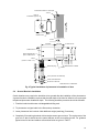
The filter from piezometer should be removed and soaked or boiled in water for about 15 minutes
or until the filter is saturated with water. The filter can be removed by opening the locking nut with
a spanner wrench. In some models the filter is removed by pulling out the filter holder. In some
other models the filter can be removed by unscrewing the conical tip.
Before replacing the filter, the end of the piezometer should be filled with water. With the filter end
of the piezometer facing up, the filter should be replaced. A small amount of water may squeeze
through the filter stone as this is done.
Assembled piezometer should quickly be inserted into a bottle or bucket off water, keeping it
submerged while it is transported to the field. Water enclosed between diaphragm and filter should
not leak out before installation of the piezometer. A saturated filter with no air gap should be
ensured for accurate readings.
5.2
Installing Piezometers in Open Standpipes
This procedure may be used for the installation of piezometers, which are in the vicinity of the
dam-site but are located outside the foundation area. For monitoring water level in an open
standpipe, sufficient time should be allowed for level to stabilize after lowering piezometer
assembly into the borehole.
5.3
Installing Piezometers in Foundations Using Sand
The procedure described herein can be used for installing piezometers in the foundation of the
earth and rock-fill dam. A traditional borehole installation requires that the total depth of the hole
be drilled to one meter past the planned piezometer installation depth. Installation procedure
should be as follows:
1. Flush the borehole with water or biodegradable drilling mud.
2. Create a sand zone using a tremie to drop wet sand to the borehole bottom. Elevate casing to
maintain casing above the sand level.
3. Tie piezometer to signal cable in the filter-end-up position.
4. Lower the piezometer into the borehole when the desired sand level is achieved.
5. After piezometer is lowered to the desired depth, add sand with a tremie and continue pulling
the casing until it is above piezometer. Continue filling with sand until at least six inches (150
mm) of sand has been layered above the piezometer.
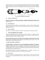
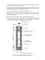
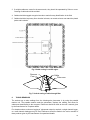
Note – There is an alternative method to the steps described in steps 4 and 5 and i.e called bag
installation. It is done by placing a piezometer into a canvas bag filled with sand and lowering the bag
into the borehole is also an acceptable piezometer placement technique (similar to the technique shown
in figure 3).
6. Isolate the piezometer by creating a bentonite clay seal above the piezometer sand zone
created in step 5. Installation specifications should be referred for thickness of seal. Typical
seal thickness is a minimum of one foot. Bentonite chips should be used and the seal should
8