1
User Manual
RSB-4210 Evaluation
Kit
Freescale i.MX53 Processor ARM® Cortex™ A8 Architecture
Copyright
The documentation and the software included with this product are copyrighted 2012
by Advantech Co., Ltd. All rights are reserved. Advantech Co., Ltd. reserves the right
to make improvements in the products described in this manual at any time without
notice. No part of this manual may be reproduced, copied, translated or transmitted
in any form or by any means without the prior written permission of Advantech Co.,
Ltd. Information provided in this manual is intended to be accurate and reliable. However, Advantech Co., Ltd. assumes no responsibility for its use, nor for any infringements of the rights of third parties, which may result from its use.
Acknowledgements
ARM is trademarks of ARM Corporation.
Freescale is trademarks of Freescale Corporation.
Microsoft Windows are registered trademarks of Microsoft Corp.
All other product names or trademarks are properties of their respective owners.
Product Warranty (2 years)
Advantech warrants to you, the original purchaser, that each of its products will be
free from defects in materials and workmanship for two years from the date of purchase.
This warranty does not apply to any products which have been repaired or altered by
persons other than repair personnel authorized by Advantech, or which have been
subject to misuse, abuse, accident or improper installation. Advantech assumes no
liability under the terms of this warranty as a consequence of such events.
Because of Advantech’s high quality-control standards and rigorous testing, most of
our customers never need to use our repair service. If an Advantech product is defective, it will be repaired or replaced at no charge during the warranty period. For outof-warranty repairs, you will be billed according to the cost of replacement materials,
service time and freight. Please consult your dealer for more details.
If you think you have a defective product, follow these steps:
1. Collect all the information about the problem encountered. (For example, CPU
speed, Advantech products used, other hardware and software used, etc.) Note
anything abnormal and list any onscreen messages you get when the problem
occurs.
2. Call your dealer and describe the problem. Please have your manual, product,
and any helpful information readily available.
3. If your product is diagnosed as defective, obtain an RMA (return merchandize
authorization) number from your dealer. This allows us to process your return
more quickly.
4. Carefully pack the defective product, a fully-completed Repair and Replacement
Order Card and a photocopy proof of purchase date (such as your sales receipt)
in a shippable container. A product returned without proof of the purchase date
is not eligible for warranty service.
5. Write the RMA number visibly on the outside of the package and ship it prepaid
to your dealer.
RSB-4210 User Manual
Part No. 2062421011
Edition 1
Printed in Taiwan
September 2012
ii
Packing List
Before setting up the system, check that the items listed below are included and in
good condition. If any item does not accord with the table, please contact your dealer
immediately.
RSB-4210 (P/N: RSB-4210CF-A78AAE)
7" LED PANEL 320N 4WR T/S 800X480(G), 97G070V1N0F-2, P/N: 96LEDKA070WV32RB1)
LCD Backlight Cable (P/N: 1700019577)
LVDS Cable (P/N: 1700014418)
Touch Cable (P/N: 1700000194)
SQFlash SD Card SLC 2G, 2CH(-40 ~ 85° C) (P/N: SQF-ISDS2-2G-ETE)
A CABLE SATA 15P/1*4P-2.5 35cm for AIMB-213 (P/N: 1700018785)
M Cable SATA 7P/SATA 7P 8CM C=R 180/180 (P/N:1700004711)
Mini USB Host Cable (P/N: 1700019076)
Mini USB Client Cable (P/N: 1700019077)
USB Type-A Cable (P/N: 1700019129)
ADAPTER 100-240 V 65 W 19 V 3.42 A 9NA0651256 (P/N: 1757003734)
A Cable 2*8P-2.0/SPEAKER*2+DC JACK*3 40CM(P/N: 1700019546-11)
F Cable IDE#2 10P-2.0/D-SUB 9P(M) 25CM (P/N: 1700100250)
Terminal connector 9P Female (P/N: 1654909900)
DVD-ROM for RSB-4210 Evaluation Kit (P/N: 2062421011)
RS-232 and RS-485 cable (P/N: 1700019474)
RS-422 cable (P/N: 1700019476)
Power Cord (Optional)
3 pin Power Cord for USA standard (P/N: 1700001524)
3 pin Power Cord for Europe standard (P/N: 170203183C)
3 pin Power Cord for UK standard (P/N: 170203180A)
Charger Board & Battery (Optional)
A cable 1*6P-2.5/1*6P-2.5 140 mm (P/N: 1700018394)
A cable 2*4P-2.0/2*4P-2.0 90 mm (P/N: 1700018395)
PCM-739 Battery charger Board (P/N: 969K073900E)
Battery 11.1 V 6300 mAh 3S3P (P/N: 1760001300)
iii
RSB-4210 User Manual
Safety Instructions
1.
2.
3.
4.
5.
6.
7.
8.
9.
10.
11.
12.
13.
14.
Read these safety instructions carefully.
Keep this User Manual for later reference.
Disconnect this equipment from any AC outlet before cleaning. Use a damp
cloth. Do not use liquid or spray detergents for cleaning.
For plug-in equipment, the power outlet socket must be located near the equipment and must be easily accessible.
Keep this equipment away from humidity.
Put this equipment on a reliable surface during installation. Dropping it or letting
it fall may cause damage.
The openings on the enclosure are for air convection. Protect the equipment
from overheating. DO NOT COVER THE OPENINGS.
Make sure the voltage of the power source is correct before connecting the
equipment to the power outlet.
Position the power cord so that people cannot step on it. Do not place anything
over the power cord.
All cautions and warnings on the equipment should be noted.
If the equipment is not used for a long time, disconnect it from the power source
to avoid damage by transient overvoltage.
Never pour any liquid into an opening. This may cause fire or electrical shock.
Never open the equipment. For safety reasons, the equipment should be
opened only by qualified service personnel.
If one of the following situations arises, get the equipment checked by service
personnel:
The power cord or plug is damaged.
Liquid has penetrated into the equipment.
The equipment has been exposed to moisture.
The equipment does not work well, or you cannot get it to work according to
the user's manual.
The equipment has been dropped and damaged.
The equipment has obvious signs of breakage.
RSB-4210 User Manual
iv
Contents
Chapter
Chapter
1
Overview...............................................1
1.1
1.2
1.3
1.4
Introduction ............................................................................................... 2
Features .................................................................................................... 2
Hardware Specifications ........................................................................... 3
Board Block Diagram ................................................................................ 4
Figure 1.1 RSB-4210 Board Block Diagram ................................ 4
2
H/W Installation....................................5
2.1
Development Kit H/W Installation.............................................................. 6
Figure 2.1 RSB-4210 Development Kit Assembly ....................... 7
2.1.1 RSB-4210 (Part-A)........................................................................ 8
2.1.2 7" LVDS LCD Module (Part-B1).................................................... 8
2.1.3 LCD Backlight Cable (Part-B2) ..................................................... 8
2.1.4 LVDS Cable (Part-B3)................................................................... 8
2.1.5 Touch Cable (Part-B4) .................................................................. 8
2.1.6 SQFlash SD Card (Part-C) ........................................................... 8
2.1.7 SATA Power Cable (Part-D) ......................................................... 8
2.1.8 SATA Cable (Part-E)..................................................................... 8
2.1.9 Mini USB Host Cable (Part-F)....................................................... 8
2.1.10 Mini USB Client Cable (Part-G) .................................................... 8
2.1.11 USB Type-A Cable (Part-H).......................................................... 9
2.1.12 Jumper (Part-I).............................................................................. 9
2.1.13 Null modem cable (Part-J) ............................................................ 9
2.1.14 19 V Power Adapter (Part-K) ........................................................ 9
2.1.15 Power Cord (Part-L)...................................................................... 9
2.1.16 Speaker & Audio Cables (Part-M)................................................. 9
2.1.17 Power Cable for Charger Board (Part-N1).................................... 9
2.1.18 Signal Cable for Charger Board (Part-N2) .................................... 9
2.1.19 Charger Board (Part-N3)............................................................... 9
2.1.20 Battery (Part-N4)........................................................................... 9
2.1.21 Keypad Cable (Part-O1) ............................................................... 9
2.1.22 Keypad (Part-O2).......................................................................... 9
2.1.23 Cable for Suspend/Reset Button (Part-P)................................... 10
2.1.24 COM Port Cable (D-SUB 9P to Housing) (Part-Q) ..................... 10
2.1.25 RS-232 Loopback (Part-R) ......................................................... 10
2.1.26 Terminal Block for CAN/RS-485 (Part-S).................................... 10
RSB-4210 Connectors ............................................................................ 10
2.2.1 Wafer for 4-wire Resistive Type Touch Screen (CN1)............... 11
Figure 2.2 Wafer for 4-wire Resistive Type Touch Screen ....... 11
2.2.2 Phoenix Connector for CAN Bus (CN2)...................................... 12
Figure 2.3 Phoenix Connector for CAN Bus .............................. 12
Figure 2.4 CAN Application ....................................................... 12
Figure 2.5 Schematics of CAN on RSB-4210............................ 12
2.2.3 Phoenix Connector for COM3, RS-485 (CN3) ............................ 13
Figure 2.6 Phoenix Connector for COM3, RS-485 .................... 13
Figure 2.7 RS-485 Application................................................... 13
Figure 2.8 Schematics of RS-485 on RSB-4210 ....................... 13
2.2.4 System Bus (CN4) ...................................................................... 14
Figure 2.9 System Bus .............................................................. 14
2.2.5 Pin Header for COM5, RS-232 (TX/RX/RTS/CTS) (CN5) .......... 15
Figure 2.10Pin Header for COM5, RS-232 (TX/RX/RTS/CTS) .. 15
2.2.6 Pin Header for COM4, 3.3V TTL (TX/RX/RTS/CTS) (CN6)........ 16
Figure 2.11Pin Header for COM4, 3.3V TTL (TX/RX/RTS/CTS) 16
2.2
v
RSB-4210 User Manual
2.2.7
2.2.8
2.2.9
2.2.10
2.2.11
2.2.12
2.2.13
2.2.14
2.2.15
2.2.16
2.2.17
2.2.18
2.2.19
2.2.20
2.2.21
2.2.22
2.2.23
2.2.24
2.2.25
2.2.26
2.2.27
2.2.28
2.2.29
2.2.30
2.2.31
2.2.32
2.2.33
2.2.34
RSB-4210 User Manual
Pin Header for I2S (CN7)............................................................ 16
Figure 2.12Pin Header for I2S.................................................... 16
LVDS0 LCD Connector (CN8) .................................................... 17
Figure 2.13LVDS0 LCD Connector ............................................ 17
Pin Header for COM1, RS-232 (TX/RX) (CN9) .......................... 18
Figure 2.14Pin Header for COM1, RS-232 (TX/RX)................... 18
Pin Header for SD2 (CN10) ........................................................ 19
Figure 2.15Pin Header for SD2 .................................................. 19
Wafer for Backlight Power and Controller (CN11) ...................... 20
Figure 2.16Wafer for Backlight Power and Controller ................ 20
MiniPCIe Connector-Latch (CN12) and Connector (CN13)........ 20
Figure 2.17MiniPCIe Connector-Latch (CN12) and Connector
(CN13)...................................................................... 20
LVDS1 LCD Connector (CN14) .................................................. 22
Figure 2.18LVDS1 LCD Connector ............................................ 22
Pin Header for Jtag (CN15) ........................................................ 23
Figure 2.19Pin Header for Jtag .................................................. 23
Wafer for SATA power (CN16) ................................................... 24
Figure 2.20Wafer for SATA power ............................................. 24
Wafer for Power ON/OFF (CN17)............................................... 25
Figure 2.21Pin Header for Power Button.................................... 25
Ethernet LAN1&2 Connector (CN18).......................................... 26
Figure 2.22Ethernet LAN1 & LAN2 Connector........................... 26
Wafer for Coin Battery (CN19).................................................... 26
Figure 2.23Wafer for Coin Battery.............................................. 26
SIM Card slot (CN20) ................................................................. 27
Figure 2.24SIM Card slot............................................................ 27
Pin Header for Reset (RST_BTN1) ............................................ 27
Figure 2.25Pin Header for Reset................................................ 27
Pin Header for Suspend (SUS_BTN1) ....................................... 28
Figure 2.26Pin Header for Suspend ........................................... 28
Pin Header for Matrix Keypad (KEYPAD1)................................. 29
Figure 2.27Pin Header for Matrix Keypad .................................. 29
Pin Header for I2C/SPI (CN21)................................................... 30
Figure 2.28Pin Header for I2C/SPI............................................. 30
Pin Header for 20x pins GPIO (GPIO1)...................................... 31
Figure 2.29Pin Header for GPIO ................................................ 31
SATA Connector (SATA_CN1)................................................... 32
Figure 2.30SATA Connector ...................................................... 32
Pin Header for USB_HUB1 (USB1)............................................ 32
Figure 2.31Pin Header for USB_HUB1 ...................................... 32
Wafer for Battery Charger Board - Power (BAT_CN1) ............... 33
Figure 2.32Wafer for Battery Charger Board - Power ................ 33
Wafer for Battery Charger Board -Control Signal (BAT_CN2).... 34
Figure 2.33Wafer for Battery Charger Board - Control Signal.... 34
USB OTG MINI-AB Connector (USB_OTG1)............................. 34
Figure 2.34USB OTG MINI-AB Connector ................................. 34
USB HUB_2&3 (Standard Type-A) (USB2) ................................ 35
Figure 2.35USB CSB_HUB_2&3 (Standard Type-A) ................. 35
VGA Connector (CRT1).............................................................. 35
Figure 2.36VGA Connector (D-SUB15)...................................... 35
HDMI Connector (HDMI_CN1) ................................................... 36
Figure 2.37HDMI Connector....................................................... 36
Box Header for LINE-OUT, LINE-IN, MIC-IN and L&R Speakers
(AUDIO1) .................................................................................... 37
Figure 2.38Box Header for LINE-OUT, LINE-IN, MIC-IN and L&R
Speakers .................................................................. 37
D-Sub9 Connector for COM2, RS-232 (TX/RX/RTS/ CTS) (COM1)
38
Figure 2.39D-Sub9 Connector for COM2, RS-232 (TX/RX/RTS/
vi
Chapter
2.3
CTS) ......................................................................... 38
2.2.35 DC-IN Power Jack(DCIN1) ......................................................... 39
Figure 2.40DC-IN Power Jack .................................................... 39
2.2.36 SD Card Slot (SD1)..................................................................... 39
Figure 2.41SD card Slot ............................................................. 39
Mechanical .............................................................................................. 40
2.3.1 Connector Location..................................................................... 40
Figure 2.42RSB-4210 Connector Position (Top) ........................ 40
Figure 2.43RSB-4210 Connector Position (Bottom)................... 40
2.3.2 RSB-4210 Board Dimension....................................................... 41
Figure 2.44RSB-4210 Board Dimension .................................... 41
3
Software Functionality ......................43
3.1
3.2
Introduction ............................................................................................. 44
Package Content..................................................................................... 44
3.2.1 Package for Making Linux System SD Storage Card ................. 44
Figure 3.1 Contents of package for making Linux system SD storage card.................................................................... 44
3.2.2 Source Code Package ................................................................ 45
Figure 3.2 Contents of Source code package ........................... 45
Setup Building Environment.................................................................... 47
3.3.1 Setenv.sh .................................................................................... 48
Building Instructions ................................................................................ 48
3.4.1 Building U-boot image "u-boot.bin" ............................................. 48
3.4.2 Building Linux Kernel image "uImage"........................................ 48
3.4.3 Build Log ..................................................................................... 49
Source Code Modification ....................................................................... 49
3.5.1 Adding a Driver to Kernel by menuconfig ................................... 49
Figure 3.3 Linux Kernel Configuration ....................................... 49
Figure 3.4 Selecting Seiko Instruments S-35390A .................... 50
Figure 3.5 Integrate Code for Seiko Instruments S-35390A...... 50
3.5.2 Changing the Boot Logo ............................................................. 50
Making Linux System Booting Media ...................................................... 51
3.6.1 Making a Linux System SD Storage Card .................................. 51
3.6.2 Booting from Onboard Flash....................................................... 52
3.6.3 Booting from SATA DOM............................................................ 52
Debug Message ...................................................................................... 52
Figure 3.6 HyperTerminal Settings for Terminal Setup ............. 53
Linux Software Applications on RSB-4210 ............................................. 53
3.8.1 Writing Your Own "Hello World!" Application and Executing on
RSB-4210 ................................................................................... 53
3.8.2 Running Pre-installed Applications on RSB-4210....................... 54
Figure 3.7 QT Demo Applications.............................................. 54
Figure 3.8 QT - Fluidlauncher demo.......................................... 55
Figure 3.9 Video demo .............................................................. 55
Figure 3.10Photo demo .............................................................. 56
Figure 3.11Result of memory testing.......................................... 56
VGA/HDMI Configuration on RSB-4210 ................................................. 57
Figure 3.12Block diagram of video configuration on RSB-4210 . 57
3.9.1 Auto Mode................................................................................... 57
Table 3.1: Output Resolution of RSB-4210 Auto Mode............. 57
3.9.2 Bypass Mode .............................................................................. 57
Table 3.2: 44 Built-in Timings of RSB-4210 Bypass Mode........ 58
Table 3.3: Auto Parameters....................................................... 59
Figure 3.13Change directory to configure CH7033B.................. 59
Figure 3.14Display all built-in timing settings.............................. 59
Figure 3.15Bypass mode configuration ...................................... 60
Figure 3.16Auto parameter selection.......................................... 60
3.3
3.4
3.5
3.6
3.7
3.8
3.9
vii
RSB-4210 User Manual
3.10
3.11
3.12
RSB-4210 User Manual
GPIO mapping define on RSB4210 ........................................................ 60
3.10.1 What is a GPIO?......................................................................... 60
3.10.2 Paths in Sysfs ............................................................................. 61
3.10.3 GPIO Mapping Table .................................................................. 63
Interface Device Reference Documentation ........................................... 63
3.11.1 I2C .............................................................................................. 63
3.11.2 C example................................................................................... 63
3.11.3 UART .......................................................................................... 67
3.11.4 CAN bus ..................................................................................... 77
3.11.5 SD card /iNand /USB Disk/SATA Disk........................................ 83
3.11.6 LAN............................................................................................. 84
3.11.7 RTC ............................................................................................ 84
3.11.8 WatchDog ................................................................................... 92
3.11.9 Audio........................................................................................... 96
3.11.10Keypad/Touchscreen.................................................................. 96
Backlight Adjustment ............................................................................ 101
viii
Chapter
1
1
Overview
This chapter briefly introduces the
RSB-4210 Platform and RSB-4210
Evaluation Kit.
1.1 Introduction
In order to offer potential RISC-based Design-to-Order-Service (DTOS) project customers with a more efficient and low risk evaluation tool, Advantech provides a variety of RISC-based evaluation kits. Before DTOS projects kicking-off, customers can
check their designs with these kits in detail more easily. The evaluation kits have
already equipped with all of the necessary H/W and S/W parts which customer will
need, thus these can reduce design efforts and speed up application developments
to meet customers' requirements.
The RSB-4210 is designed as a single board computer (SBC) solution, with adopting
Freescale i.MX53 processor based on ARM® Cortex™ A8 architecture, which is a
complete 32-bit, up to 1GHz speed SoC engine. It provides customers with a high
performance board subsystem based on ARM® Cortex™ A8 technology with characteristics of ready-to-run, compact, and easy-to-expansion in order to meet customers'
versatile needs. With the flexible I/O interfaces and complete hardware and software
solutions, RSB-4210 is a fast time-to-market platform for customers to develop their
applications and products easily without considering system integration.
The RSB-4210 Evaluation Kit is a complete system designed for customers to evaluate the RSB-4210. It integrates all of the solutions that developers will need, based
on the RSB-4210 main board, into a package that provides customers an effortless
system platform for project evaluation, application development, and solution feasibility testing that decreases lead-time and lowers initial expense. The RSB-4210 Evaluation Kit has already integrated complete certified functions under Linux's test kits
making project development and implementation becomes an easy and risk-free way
at the starting point.
1.2 Features
RSB-4210 adopts Freescale i.MX53 Processor - ARM® Cortex™ A8 architecture as
its SoC solution. The main features of this platform are heatsink-less, compact, reliable & great power management. Therefore, the platform will be suitable for the following applications:
Economical HMI (Human Machine Interface)
Self Service / Access Control
Fleet management / Navigation
Hand-held data collector
And the main features of Freescale i.MX53 processor are shown as follows:
ARM® Cortex™-A8 1GHz high performance processor
Supports OpenGL ES 2.0 and OpenVG® 1.1 hardware accelerators
Supports full HD 1080p video decode and HD 720p video encode hardware
engine Freescale Smart Speed® Technology support low power consumption
I/O through 3.3 V I/O voltage and wide working temperature by industrial design
concept
Rich I/O for high expansion capability: UART(5), Dual LVDS, Audio, USB Host,
USB OTG, Dual LAN, SD(2), SATA(1), GPIO(20), I2C(2), SPI(1), I2S(1),
CAN(1), Keypad 6X6, Touch, Mini PCI-E and System Bus
Supports SATA storage interface and CAN bus for vehicle application
Supports Android2.3, Embedded Linux2.6 and Windows Embedded Compact 7
Support wide working temperature -40 ~ 85° C operation temperature
(optional)
RSB-4210 User Manual
2
Item
Chapter 1
1.3 Hardware Specifications
Description
Kernel
CPU
Freescale i.MX53 1GHz (ARM Cortex A8)
2D/3D Accelerators
Support OpenGL ES 2.0 and OpenVG™ 1.1 hardware accelerators
512MB (Optional: 256MB)
Onboard Flash
2GB (Optional: None)
RTC
Yes
Watchdog Timer
Yes
Reset
H/W reset & S/W reset
I/O
COM
COM 1, RS-232, 2–wire(TX/RX), Pin header, (Debug port)
COM 2, RS-232, D-Sub9 Connector(TX/RX/RTS/CTS)
COM 3, RS-485, 2-pin Phoenix Connector
COM 4, 3.3 V TTL, 4–wire(TX/RX/RTS/CTS), Pin header
COM 5, RS-232, 4–wire(TX/RX/RTS/CTS), Pin header
Ethernet LAN
2 x 10/100 BASE-T (RJ-45)
USB Port
3 x USB 2.0 (High speed)
USB OTG
1 x USB 2.0 OTG (High speed)
SD/MMC
2 x SDIO/MMC interface (SD slot x 1+ pin header x 1)
Mini PCI-E
1 x (Control by USB interface only)
SIM Card slot
1x
SATA
1x
Touch Screen
1 x 4 - wire resistive type interface
System Bus
Yes (Address: 25 pins, data: 16 pins)
2
I C Interface
2x
I2S Interface
1x
SPI Interface
1x
CAN BUS
1x
Hotkey/
Matrix keypad
Support 6 x 6 matrix keypad
GPIO
20 pins 3.3 V TTL level GPIOs
Buzzer control
Yes
Multimedia
Graphic Chip
CPU internal LCD controller
LCD Resolution
Default: 800 x 480 7” WVGA
Optional: 320 x 240 ~ 1920 x 1080
Dual LVDS
2 x 24-bit LVDS
HDMI
1 x (Co-lay with VGA)
VGA
1 x (Co-lay with HDMI)
Brightness/
Backlight Control
Yes
Audio
Line-in(Stereo),Line-out(Stereo),Speak-Out(Stereo)&Mic-in(Mono)
Power
DC-input
9 ~ 24 V 5%
Battery Support
Yes (With external battery and charger board thru connector)
3
RSB-4210 User Manual
Overview
System RAM
Power Consumption
Normal Run ~2.3 W
Full Run ~3.8 W
Power Control
1 x Power ON/OFF Pin header
1 x H/W reset Pin header
1 x Suspend Pin header
Power Management
-Standard mode
-Idle mode
Mechanical and Environmental
Board size
146 x 102 x 20 mm (PCB thickness 1.6 mm; 8 layer)
Weight
110 g
Operation Temperature
0 ~ 60° C (32 ~ 140° F)
(-40 ~ 85° C by component change)
Operating Humidity
5% ~ 95% Relative Humidity, non condensing
Vibration
3.5 G, 1000 times
Others
RoHS
Yes
Certification
CE/FCC Class A
O.S
Embedded Linux 2.6.35 (Default), Android 2.3.4,
and Windows Embedded Compact 7
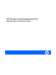
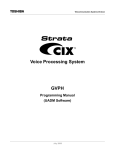
1.4 Board Block Diagram
Figure 1.1 RSB-4210 Board Block Diagram
RSB-4210 User Manual
4
Chapter
2
2
H/W Installation
This chapter introduces the setup
procedures of the RSB-4210 hardware, including instructions on
setting jumpers and connecting
peripherals, switches, indicators
and mechanical drawings.
Be sure to read all safety precautions before you begin this installation procedure.
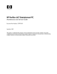
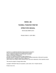
2.1 Development Kit H/W Installation
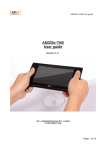
The Figure 2-1 is RSB-4210 Evaluation Kit Assembly, and the detail descriptions with
Advantech P/N are shown as below.
Item
Description
Advantech P/N
Part-A
RSB-4210
(P/N: RSB-4210CF-A78AAE)
Part-B1
7” LCD-LED Backlight, LVDS, 800x480, T/S,
97G070V1N0F-2
(P/N: 96LEDK-A070WV32RB1)
Part-B2
LCD Backlight Cable
(P/N: 1700019577)
Part-B3
LVDS Cable
(P/N: 1700014418)
Part-B4
Touch Cable
(P/N: 1700000194)
Part-C
SQFlash SD Card, SLC 2GB, (-40~85°C)
(P/N: SQF-ISDS2-2G-ETE)
Part-D
SATA Power Cable
(P/N: 1700018785)
Part-E
SATA Cable
(P/N: 1700004711)
Part-F
Mini USB Host Cable
(P/N: 1700019076)
Part-G
Mini USB Client Cable
(P/N: 1700019077)
Part-H
USB Type-A Cable
(P/N: 1700019129)
Part-J
Null modem cable
(P/N: 1700091002)
Part-K
ADAPTER, 100-240V, 19V, 3.42A.
(P/N: 1757003734)
Part-L
3 pin Power Cord (USA Standard) [Optional]
3 pin Power Cord (Europe standard) [Optional]
3 pin Power Cord (UK standard) [Optional]
(P/N: 1700001524)
(P/N: 170203183C)
(P/N: 170203180A)
Part-M
Speaker & Audio Cables
(P/N: 1700019546-11)
Part-N1
Power Cable for Charger Board [Optional]
(P/N: 1700018394)
Part-N2
Signal Cable for Charger Board [Optional]
(P/N: 1700018395)
Part-N3
Charger Board [Optional]
(P/N: 969K073900E)
Part-N4
Battery [Optional]
(P/N: 1760001300)
Part-O1
8*8 Keypad Cable [Optional]
(P/N: 1703200180)
Part-O2
8*8 Keypad [Optional]
(P/N: 96969315A0E)
Part-Q
COM Port Cable
(P/N: 1700100250)
Part-R
RS-232 Loopback
(P/N: 1654909900)
Part-S
Terminal Block for CAN/RS-485
(P/N: 1652002209)
RSB-4210 User Manual
6
Chapter 2
H/W Installation
Figure 2.1 RSB-4210 Development Kit Assembly
7
RSB-4210 User Manual
2.1.1 RSB-4210 (Part-A)
RSB-4210 is a cost-effective, low-power, and high-performance SBC (Single Board
Computer) without a heatsink, geared to satisfy the needs for various industrial computing equipments. Based on Freescale i.MX53 Processor - ARM® Cortex™ A8
architecture, there are DDR3, iNAND flash and other main ICs. RSB-4210 offers convenient connector layout, simple assembly, multiple common I/Os, and includes dual
10/100Mbps Ethernet, three USB (Universal Serial Bus) 2.0 and five serial ports for
easy system expansibility.
2.1.2 7" LVDS LCD Module (Part-B1)
The 7.0 inch Color TFT-LCD Module with 4-wires resistive type touch sensor. The
module is designed with wide viewing angle; wide operating temperature and long life
LEDs backlight is well suited to be the display units for Industrial Applications. LED
driving board for backlight unit is included in this panel and the structure of the LED
units is replaceable. It's built in timing controller and LVDS interface. The display supports the WVGA (800 (H) x 480(V)) screen format and 16.2 M colors (RGB 24bits) or
262 K (RGB 18 bits) selectable.
2.1.3 LCD Backlight Cable (Part-B2)
The LVDS backlight cable connects RSB-4210 (CN11) with the LCD backlight connector of 7" LVDS LCD Module.
2.1.4 LVDS Cable (Part-B3)
The LVDS cable connects RSB-4210 LVDS0 connector (CN8) with the LCD signal
connector of 7" LVDS LCD Module.
2.1.5 Touch Cable (Part-B4)
The touch cable connects RSB-4210 (CN1) with the touch connector of 7" LVDS LCD
Module.
2.1.6 SQFlash SD Card (Part-C)
The SQFlash SD card is a standard SD device. It is the flash-based solid-state drive
available and uses SLC NAND flash memory, making it ideal as an embedded SSD
solution. It connects on SD1 of RSB-4210.
2.1.7 SATA Power Cable (Part-D)
The SATA power cable provides the power signal for SATA HDD by connecting RSB4210 (CN16) and the SATA HDD.
2.1.8 SATA Cable (Part-E)
The SATA cable provides the control signal with SATA HDD by connecting RSB-4210
(SATA_CN1) with the SATA HDD.
2.1.9 Mini USB Host Cable (Part-F)
The mini USB Host cable connects RSB-4210 (USB_OTG1) with one USB client
device. For example, USB mouse/keyboard.
2.1.10 Mini USB Client Cable (Part-G)
The mini USB Client cable connects RSB-4210 (USB_OTG1) with PC or NB.
RSB-4210 User Manual
8
The USB extend cable provide Type-A for USB device. For example, USB mouse/
keyboard.
2.1.12 Jumper (Part-I)
When plug-in the adapter with the wafer (CN17) shorted by this jumper, the system
will power-on.
The null modem cable connects RSB-4210 COM ports with a serial device.
2.1.14 19 V Power Adapter (Part-K)
The AC-to-DC power device provides a 19 V DC output (65 W max) with constant
voltage sources (100 V ~ 240 V).
2.1.15 Power Cord (Part-L)
3P Power Cord (USA, Europe or UK standard) for 19 V Power Adapter AC input.
2.1.16 Speaker & Audio Cables (Part-M)
The cable connects with RSB-4210 (AUDIO1) and LINE-OUT, LINE-IN, MIC-IN and
L&R Speakers.
2.1.17 Power Cable for Charger Board (Part-N1)
The cable provides the power for charger board. It connects RSB-4210 (BAT_CN1)
with the charger board (CN2).
2.1.18 Signal Cable for Charger Board (Part-N2)
The cable provides the control signal for charger board. It connects RSB-4210
(BAT_CN2) with the charger board (CN1).
2.1.19 Charger Board (Part-N3)
The charger board provides 12 V power to charge the battery when plug-in a 19 V
adapter, and RSB-4210 can read the battery status through this charger board.
Note!
It is necessary to use 19 V adapter for charger board rather than 12 V.
2.1.20 Battery (Part-N4)
The battery can provide the power with RSB-4210 without any adapter.
2.1.21 Keypad Cable (Part-O1)
The keypad cable connects RSB-4210 (KEYPAD1) with the keypad.
2.1.22 Keypad (Part-O2)
8*8 arrays of 64 normally open single-pole switches. (6*6 region of keypad are available when using RSB-4210.)
9
RSB-4210 User Manual
H/W Installation
2.1.13 Null modem cable (Part-J)
Chapter 2
2.1.11 USB Type-A Cable (Part-H)
2.1.23 Cable for Suspend/Reset Button (Part-P)
The cable is used to extend the Suspend/Reset function by a specific button.
2.1.24 COM Port Cable (D-SUB 9P to Housing) (Part-Q)
The cable is used to extend COM port 9pin header from RSB-4210 to D-SUB 9P
serial port connector.
2.1.25 RS-232 Loopback (Part-R)
The terminal connector 9P female is used to test RS-232 loopback function.
2.1.26 Terminal Block for CAN/RS-485 (Part-S)
The terminal block can be extended with extra two cables to connect RSB-4210
CAN/RS-485 function with the others CAN/RS-485 devices.
2.2 RSB-4210 Connectors
The following table shows the connector list of RSB-4210.
Connector
Description
CN 1
Wafer for 4-wire Resistive Type Touch Screen
CN 2
Phoenix Connector for CAN Bus
CN 3
Phoenix Connector for COM3, RS-485
CN 4
System Bus
CN 5
Pin Header for COM5, RS-232 (TX/RX/RTS/CTS)
CN 6
Pin Header for COM4, 3.3V TTL (TX/RX/RTS/CTS)
CN 7
Pin Header for I2S
CN 8
LVDS0 LCD Connector
CN 9
Pin Header for COM1, RS-232 (TX/RX)
CN 10
Pin Header for SD2
CN 11
Wafer for Backlight Power and Controller
CN 12
MiniPCIe Connector-Latch
CN 13
MiniPCIe Connector
CN 14
LVDS1 LCD Connector
CN 15
Pin Header for Jtag
CN 16
Wafer for SATA Power
CN 17
Wafer for Power ON/OFF
CN 18
Ethernet LAN1&2 Connector
CN 19
Wafer for Coin Battery
CN 20
SIM Card Slot
RST_BTN1
Pin Header for Reset
SUS_BTN1
Pin Header for Suspend
KEYPAD1
Pin Header for Matrix Keypad
CN21
Pin Header for I2C/SPI
GPIO1
Pin Header for 20x pins GPIO
SATA_CN1
SATA Connector
USB1
Pin Header for USB_HUB1
BAT_CN1
Wafer for Battery Charger Board – Power
RSB-4210 User Manual
10
USB_OTG1
USB OTG MINI-AB Connector
USB2
USB_HUB_2&3 (Standard Type-A)
CRT1
VGA Connector
HDMI_CN1
HDMI Connector
AUDIO1
Box Header for LINE-OUT, LINE-IN, MIC-IN and L&R Speakers
COM1
D-Sub9 Connector for COM2, RS-232 (TX/RX/RTS/CTS)
DCIN1
DC-IN Power Jack
SD1
SD Card Slot
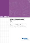
Wafer for 4-wire Resistive Type Touch Screen (CN1)
The touch screen interface performs all sampling, averaging, ADC range checking,
and control for a wide variety of analog resistive touch screens. This controller only
interrupts the processor when a meaningful change occurs.
Figure 2.2 Wafer for 4-wire Resistive Type Touch Screen
Pin
Description
Pin
Description
1
Touch_Y-
2
Touch_Y+
3
Touch_X-
4
Touch_X+
11
RSB-4210 User Manual
H/W Installation
Wafer for Battery Charger Board – Control Signal
Chapter 2
2.2.1
BAT_CN2
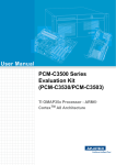
2.2.2 Phoenix Connector for CAN Bus (CN2)
RSB-4210 supports one CAN bus, while CN2 is a phoenix connector for CAN bus.
Note!
For CAN applications, the two ends of the cable will have a termination
resistor connected across the two wires. Without termination resistors,
reflections of fast driver edges can cause multiple data edges that can
cause data corruption. Please refer to Figure 2.4 and Figure 2.5 to adding a termination resistor (120 ohms) on your end device (R271 of RSB4210, default is none) to avoid this situation.
Figure 2.3 Phoenix Connector for CAN Bus
Pin
Description
Pin
Description
1
CAN_D+
2
CAN_D-
Figure 2.4 CAN Application
Figure 2.5 Schematics of CAN on RSB-4210
RSB-4210 User Manual
12
RSB-4210 supports one RS-485 interface, while CN3 is a phoenix connector for RS485.
Note!
Figure 2.6 Phoenix Connector for COM3, RS-485
Pin
Description
Pin
Description
1
RS485_TXD-
2
RS485_TXD+
Figure 2.7 RS-485 Application
Figure 2.8 Schematics of RS-485 on RSB-4210
13
RSB-4210 User Manual
H/W Installation
For RS-485 applications, the two ends of the cable will have a termination resistor connected across the two wires. Without termination resistors, reflections of fast driver edges can cause multiple data edges that
can cause data corruption. Please refer to Figure 2.7 and Figure 2.8 to
adding a termination resistor (120 ohms) on your end device (R289 of
RSB-4210, default is 120 ohms) to avoid this situation.
Chapter 2
2.2.3 Phoenix Connector for COM3, RS-485 (CN3)
2.2.4 System Bus (CN4)
The RSB-4210 provides the system bus via PCI104+ connector for extend device
used. The pin assignment is shown as below.
Figure 2.9 System Bus
Pin Description
Pin Description
Pin Description
Pin Description
A1
B1
C1
D1
N/C
N/C
GND
N/C
A2
GND
B2
N/C
C2
DIO_3V3
D2
DIO_3V3
A3
EX_GPIO_8
B3
IMX_GPIO4
C3
IMX_GPIO3
D3
IMX_GPIO2
A4
N/C
B4
N/C
C4
DIO_3V3
D4
DIO_3V3
A5
SysBus_A0
B5
SysBus_A1
C5
SysBus_A15
D5
SysBus_A14
A6
SysBus_A2
B6
SysBus_A3
C6
SysBus_A13
D6
SysBus_A12
A7
SysBus_A4
B7
SysBus_A5
C7
SysBus_A11
D7
SysBus_A10
A8
SysBus_A6
B8
SysBus_A7
C8
SysBus_A9
D8
SysBus_A8
A9
SysBus_A16
B9
SysBus_A17
C9
SysBus_A24
D9
N/C
A10 SysBus_A18
B10 SysBus_A19
C10 N/C
D10 SysBus_OE
A11 SysBus_A20
B11 SysBus_A21
C11 SysBus_RW
D11 GND
A12 SysBus_A22
B12 SysBus_A23
C12 N/C
D12 N/C
A13 DIO_3V3
B13 N/C
C13 SysBus_CS0
D13 SysBus_CS1
A14 SysBus_D0
B14 SysBus_D1
C14 SysBus_D15
D14 SysBus_D14
A15 SysBus_D2
B15 SysBus_D3
C15 SysBus_D13
D15 SysBus_D12
A16 SysBus_D4
B16 SysBus_D5
C16 SysBus_D11
D16 SysBus_D10
A17 SysBus_D6
B17 SysBus_D7
C17 SysBus_D9
D17 SysBus_D8
A18 N/C
B18 N/C
C18 N/C
D18 N/C
A19 N/C
B19 N/C
C19 N/C
D19 N/C
A20 N/C
B20 N/C
C20 N/C
D20 N/C
A21 N/C
B21 N/C
C21 N/C
D21 N/C
A22 N/C
B22 N/C
C22 SysBus_BCLK
D22 GND
A23 N/C
B23 N/C
C23 N/C
D23 GND
A24 N/C
B24 N/C
C24 SysBus_EB1
D24 DIO_3V3
A25 N/C
B25 N/C
C25 N/C
D25 DIO_3V3
RSB-4210 User Manual
14
B26 N/C
C26 N/C
D26 N/C
A27 N/C
B27 SysBus_LBA
C27 5 V_EXT
D27 5V_EXT
A28 SysBus_WP
B28 N/C
C28 SysBus_Wait
D28 N/C
A29 N/C
B29 N/C
C29 N/C
D29 N/C
A30 SysBus_Wait
B30 N/C
C30 GND
D30 N/C
2.2.5 Pin Header for COM5, RS-232 (TX/RX/RTS/CTS) (CN5)
Figure 2.10 Pin Header for COM5, RS-232 (TX/RX/RTS/CTS)
Pin
Description
Pin
Description
1
N/C
2
N/C
3
COM5_RXD
4
COM5_RTS
5
COM5_TXD
6
COM5_CTS
7
N/C
8
N/C
9
GND
10
N/C
15
RSB-4210 User Manual
H/W Installation
CN5 is a 4-wire (TX/RX/RTS/CTS) RS-232 port which provides connections between
serial devices (For example, GPS, GSM and Bluetooth devices etc.) or a communication network.
Chapter 2
A26 SysBus_nEB0
2.2.6 Pin Header for COM4, 3.3V TTL (TX/RX/RTS/CTS) (CN6)
CN6 is a 4-wire (TX/RX/RTS/CTS) 3.3 V TTL signal which provides connections
between serial devices (For example, GPS, GSM and Bluetooth devices etc.) or a
communication network.
Figure 2.11 Pin Header for COM4, 3.3V TTL (TX/RX/RTS/CTS)
2.2.7 Pin Header for I2S (CN7)
RSB-4210 provides one I2S interface for user to expand their applications, and CN7
is the pin header for I2S interface.
Figure 2.12 Pin Header for I2S
Pin
Description
1
AUDIO_CLK
2
AUD3_TXD
3
AUD3_TXC
4
N/C
5
AUD3_TXFS
6
N/C
7
AUD3_RXD
8
N/C
9
GND
10
DIO_3V3
RSB-4210 User Manual
Pin
16
Description
RSB-4210 supports dual LVDS LCD Interfaces (24+24 bit), in which CN8 is LVDS0
(24 bit) while CN14 is LVDS1 (24bit). The pin assignment of LVDS0 (CN8) is shown
as below.
Chapter 2
2.2.8 LVDS0 LCD Connector (CN8)
H/W Installation
Figure 2.13 LVDS0 LCD Connector
Pin
Description
Pin
Description
1
3.3 V
2
3.3 V
3
3.3 V
4
3.3 V
5
LVDS0_TX0-
6
LVDS0_TX0+
7
GND
8
LVDS0_TX1-
9
LVDS0_TX1+
10
GND
11
LVDS0_TX2-
12
LVDS0_TX2+
13
GND
14
LVDS0_CLK-
15
LVDS0_CLK+
16
GND
17
3.3 V
18
N/C
19
LVDS0_TX3-
20
LVDS0_TX3+
17
RSB-4210 User Manual
2.2.9 Pin Header for COM1, RS-232 (TX/RX) (CN9)
CN9 is a 2-wire (TX/RX) RS-232 port which provides connections between serial
devices (For example, GPS, GSM and Bluetooth devices etc.) or a communication
network.
Figure 2.14 Pin Header for COM1, RS-232 (TX/RX)
Pin
Description
Pin
Description
1
N/C
2
N/C
3
COM1_RXD
4
N/C
5
COM1_TXD
6
N/C
7
N/C
8
N/C
9
GND
10
N/C
RSB-4210 User Manual
18
Figure 2.15 Pin Header for SD2
Pin
Description
Pin
Description
1
GND
2
GND
3
SD4_DATA1
4
SD4_CLK
5
SD4_DATA0
6
SD4_CMD
7
SD4_DATA3
8
SD4_CD
9
SD4_DATA2
10
3V3
11
N/C
12
N/C
19
RSB-4210 User Manual
H/W Installation
The SD/MMC Slots are 3.3 V powered, which are able to be extended for SD slot
module and SDIO interface module with the following features:
Fully compatible with the MMC system specification version 3.2
Compatible with the SD Memory Card specification 1.01, and SD I/O specification 1.1 with 1/4 channel(s)
Block-based data transfer between MMC card and SDHC (stream mode not
supported)
100 Mbps maximum data rate in 4-bit mode, SD bus clock up to 25MHz
Chapter 2
2.2.10 Pin Header for SD2 (CN10)
2.2.11 Wafer for Backlight Power and Controller (CN11)
This wafer provides DC +12 V, DC +5 V, back-light on/off control signal and 0 ~ 5 V
PWM dimming control to inverter. Strongly suggest user chooses the inverter that
dimming control is by PWM to fit development kit design.
Figure 2.16 Wafer for Backlight Power and Controller
Pin
Description
Pin
Description
1
GND
2
GND
3
BLK_PWR_EN
4
BLK_PWR_EN
5
Brightness
6
PWM1
7
12 V
8
5V
2.2.12 MiniPCIe Connector-Latch (CN12) and Connector (CN13)
RSB-4210 supports a MiniPCIe Interface. The pin assignment is shown as below.
Figure 2.17 MiniPCIe Connector-Latch (CN12) and Connector (CN13)
RSB-4210 User Manual
20
Description
Pin
Description
1
nWAKE
2
DIO_3V3
3
N/C
4
N/C
5
N/C
6
IO_1V5
7
nCLKREQ
8
UIM_PWR
GND
10
UIM_DATA
11
PCIe_CLK_N
12
UIM_CLK
13
PCIe_CLK_P
14
UIM_RESET
15
GND
16
UIM_VPP
17
N/C
18
GND
19
N/C
20
N/C
21
GND
22
nRESET_OUT
23
PCIe_RX0_N
24
DIO_3V3
25
PCIe_RX0_P
26
GND
27
GND
28
IO_1V5
29
GND
30
PCIe_SMBCLK
31
PCIe_TX0_N
32
PCIe_SMBDAT
33
PCIe_TX0_P
34
GND
35
GND
36
USB_HUB4_D-
37
GND
38
USB_HUB4_D+
39
N/C
40
GND
41
N/C
42
LED_WWAN
43
GND
44
LED_WLAN
45
N/C
46
LED_WPAN
47
N/C
48
IO_1V5
49
N/C
50
GND
51
N/C
52
DIO_3V3
53
N/C
54
N/C
55
GND
56
GND
21
RSB-4210 User Manual
H/W Installation
9
Chapter 2
Pin
2.2.13 LVDS1 LCD Connector (CN14)
RSB-4210 supports dual LVDS LCD Interfaces (24+24bit), in which CN8 is LVDS0
(24 bit) while CN14 is LVDS1 (24 bit). The pin assignment of LVDS1 (CN14) is shown
as below.
Figure 2.18 LVDS1 LCD Connector
Pin
Description
Pin
Description
1
5V
2
5V
3
5V
4
5V
5
LVDS1_TX0-
6
LVDS1_TX0+
7
GND
8
LVDS1_TX1-
9
LVDS1_TX1+
10
GND
11
LVDS1_TX2-
12
LVDS1_TX2+
13
GND
14
LVDS1_CLK-
15
LVDS1_CLK+
16
GND
17
N/C
18
N/C
19
LVDS1_TX3-
20
LVDS1_TX3+
RSB-4210 User Manual
22
RSB-4210 provides one Jtag interface for debugging CPU. CN15 is the pin header
for Jtag interface.
H/W Installation
Figure 2.19 Pin Header for Jtag
Pin
Description
Pin
Description
1
JTAG_TCK
2
GND
3
JTAG_TMS
4
GND
5
JTAG_TDO
6
GND
7
JTAG_TDI
8
IO_3V3
9
JTAG_TRST
10
N/C
23
Chapter 2
2.2.14 Pin Header for Jtag (CN15)
RSB-4210 User Manual
2.2.15 Wafer for SATA power (CN16)
CN16 provides DC +5 V for SATA device. The pin assignment is shown as below.
Figure 2.20 Wafer for SATA power
Pin
Description
Pin
Description
1
SATA_5 V
2
GND
3
GND
4
N/C
RSB-4210 User Manual
24
When plug-in the adapter with CN17 shorted by a jumper, the system will power-on.
Or you can connect this wafer with an external button to control the power ON/OFF.
Note!
If your system cannot power-on with an adapter, please check this
wafer in advance. There should be a jumper or external button on the
wafer.
Chapter 2
2.2.16 Wafer for Power ON/OFF (CN17)
H/W Installation
Figure 2.21 Pin Header for Power Button
Pin
Description
Pin
Description
1
PWR_BTN+
2
PWR_BTN-
25
RSB-4210 User Manual
2.2.17 Ethernet LAN1&2 Connector (CN18)
RSB-4210 supports dual LAN. One is extended from CPU module board directly and
another is extended from system bus. Both of them support 10/100 Mbps transfer
rates and are compliant with IEEE 802.3.
Note!
LAN connector with LED indicator: green LED indicates Ethernet active,
while yellow LED indicates Ethernet speed 10/100.
Figure 2.22 Ethernet LAN1 & LAN2 Connector
2.2.18 Wafer for Coin Battery (CN19)
CN19 is used for connecting with coin battery. The pin assignment is shown as
below.
Figure 2.23 Wafer for Coin Battery
Pin
Description
Pin
Description
1
COIN_RTC
2
GND
RSB-4210 User Manual
26
Chapter 2
2.2.19 SIM Card slot (CN20)
RSB-4210 provides a SIM card slot for MiniPCIe devices.
H/W Installation
Figure 2.24 SIM Card slot
2.2.20 Pin Header for Reset (RST_BTN1)
RST_BTN1 is used for resetting the system. You can connect it with an external button for application. The pin assignment is shown as below.
Figure 2.25 Pin Header for Reset
Pin
Description
Pin
Description
1
nRESET
2
GND
27
RSB-4210 User Manual
2.2.21 Pin Header for Suspend (SUS_BTN1)
SUS_BTN1 is used to making system entering into suspend mode or resume from
suspend mode. You can connect it with an external button for applications. The pin
assignment is shown as below.
Figure 2.26 Pin Header for Suspend
Pin
Description
Pin
Description
1
nSUSPEND
2
GND
RSB-4210 User Manual
28
Figure 2.27 Pin Header for Matrix Keypad
Pin
Description
Pin
Description
1
KEY_COL2
2
KEY_ROW2
3
KEY_COL3
4
KEY_ROW3
5
KEY_COL4
6
KEY_ROW4
7
KEY_COL5
8
KEY_ROW5
9
KEY_COL6
10
KEY_ROW6
11
KEY_COL7
12
KEY_ROW7
29
RSB-4210 User Manual
H/W Installation
The keypad circuitry scans a 6*6 array of 36 normal-open, single-pole switches. Any
one or two keys depressed will be de-bounced and decoded. An interrupt is generated whenever a stable set of depressed keys is detected. The keypad interface:
Provides scanning, de-bounce, and decoding for a 36-key switch array
Scans a 6-row by 6-column matrix
May decode 2 keys at once
Generates an interrupt when a new stable key is determined
Generates a 3-key reset interrupt as well
Chapter 2
2.2.22 Pin Header for Matrix Keypad (KEYPAD1)
2.2.23 Pin Header for I2C/SPI (CN21)
RSB-4210 provides two I2C and one SPI interface with user to expand their applications. CN21 is the pin header for I2C/SPI interface. The pin assignment is shown as
below.
Figure 2.28 Pin Header for I2C/SPI
Pin
Description
Pin
Description
1
GND
2
SPI_IRQ
3
I2C1_SCL
4
SPI_MISO
5
I2C1_SDA
6
SPI_MOSI
7
I2C3_SCL
8
SPI_CS0
9
I2C3_SDA
10
SPI_CLK
11
DIO_3V3
12
DIO_3V3
RSB-4210 User Manual
30
GPIO1 is extended for 20x pins 3.3V TTL Level GPIO. GPIO1~4 pins are coming
from CPU directly while GPIO5~20 pins are extended from IC PCA9555. The pin
assignment is shown as below.
Chapter 2
2.2.24 Pin Header for 20x pins GPIO (GPIO1)
H/W Installation
Figure 2.29 Pin Header for GPIO
Pin
Description
Pin
Description
1
GND
2
DIO_3V3
3
IMX_GPIO1
4
IMX_GPIO2
5
IMX_GPIO3
6
IMX_GPIO4
7
EX_GPIO_5
8
EX_GPIO_6
9
EX_GPIO_7
10
EX_GPIO_8
11
EX_GPIO_9
12
EX_GPIO_10
13
EX_GPIO_11
14
EX_GPIO_12
15
EX_GPIO_13
16
EX_GPIO_14
17
EX_GPIO_15
18
EX_GPIO_16
19
EX_GPIO_17
20
EX_GPIO_18
21
EX_GPIO_19
22
EX_GPIO_20
31
RSB-4210 User Manual
2.2.25 SATA Connector (SATA_CN1)
RSB-4210 supports one SATA Interface thru SATA_CN1. (Both SATA DOM and
SATA HDD support.) The pin assignment is shown as below.
Figure 2.30 SATA Connector
Pin
Description
Pin
Description
1
GND
2
SATA_TX+
3
SATA_TX-
4
GND
5
SATA_RX-
6
SATA_RX+
7
GND
2.2.26 Pin Header for USB_HUB1 (USB1)
The USB port is extended from USB_HUB1. The pin assignment is shown as below.
Figure 2.31 Pin Header for USB_HUB1
Pin
Description
Pin
Description
1
5V
2
CSB_HUB1_Data -
3
CSB_HUB1_Data +
4
GND
5
GND (Chassis Ground)
RSB-4210 User Manual
32
BAT_CN1 provides the power with battery charger board. +VIN_ADP is the voltage
from adapter to battery charge board; +VIN is the voltage from battery charge board
to RSB-4210. The pin assignment is shown as below.
Chapter 2
2.2.27 Wafer for Battery Charger Board - Power (BAT_CN1)
H/W Installation
Figure 2.32 Wafer for Battery Charger Board - Power
Pin
Description
Pin
Description
1
+VIN_ADP (For Battery)
2
+VIN_ADP (For Battery)
3
GND
4
GND
5
+VIN (For RSB-4210)
6
+VIN (For RSB-4210)
33
RSB-4210 User Manual
2.2.28 Wafer for Battery Charger Board -Control Signal (BAT_CN2)
BAT_CN2 provides the I2C control signal with battery charger board. The pin assignment is shown as below.
Figure 2.33 Wafer for Battery Charger Board - Control Signal
Pin
Description
Pin
Description
1
3.3 V_STB
2
GND
3
I2C3_SCL_BAT
4
N/C
5
I2C3_SDA_BAT
6
N/C
7
Charger_board_IN#
8
N/C
2.2.29 USB OTG MINI-AB Connector (USB_OTG1)
The RSB-4210 has a single USB OTG mini-AB port which can be used as a USB client to link with PC or a USB host device. For USB client applications, users could
upload or download files to any folder in Windows CE and create a synchronous
folder between PC and RSB-4210 thru this connector. For USB host applications,
users can connect with USB devices, for example, USB mouse and USB keypad.
Figure 2.34 USB OTG MINI-AB Connector
Pin
Description
Pin
Description
1
5V
2
Data -
3
Data +
4
USBOTG_ID
5
GND
RSB-4210 User Manual
34
The USB interface provides full speed serial communications ports, which includes
the following features:
Compliance with the USB 2.0 specification
Transceiver buffers integrated, over-current protection on ports
Supports power management
Operates as a master on the bus
2.2.31 VGA Connector (CRT1)
RSB-4210 supports a standard VGA Interface (D-SUB15). The pin assignment is
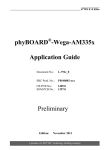
shown as below.
Figure 2.36 VGA Connector (D-SUB15)
Pin
Description
Pin
Description
1
CRT_R
2
CRT_G
3
CRT_B
4
N/C
5
GND
6
GND
7
GND
8
GND
9
+5 V
10
GND
11
N/C
12
DDC_SD_CRT
13
HSYNC
14
VSYNC
15
DDC_SC_CRT
35
RSB-4210 User Manual
H/W Installation
Figure 2.35 USB CSB_HUB_2&3 (Standard Type-A)
Chapter 2
2.2.30 USB HUB_2&3 (Standard Type-A) (USB2)
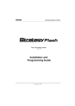
2.2.32 HDMI Connector (HDMI_CN1)
RSB-4210 supports a standard HDMI Interface. The pin assignment is shown as
below.
Figure 2.37 HDMI Connector
Pin
Description
Pin
Description
1
HDMI_TD2+
2
GND
3
HDMI_TD2-
4
HDMI_TD1+
5
GND
6
HDMI_TD1-
7
HDMI_TD0+
8
GND
9
HDMI_TD0-
10
HDMI_CLK+
11
GND
12
HDMI_CLK-
13
HDMI_CEC
14
HDMI_Reserved
15
DDC_SC_HD
16
DDC_SD_HD
17
GND
18
+5V_HDMI
19
HPD
RSB-4210 User Manual
36
The box header is used for audio input / output signal port, and the speaker-out uses
a 2W amplifier. The pin assignment is shown as below.
Chapter 2
2.2.33 Box Header for LINE-OUT, LINE-IN, MIC-IN and L&R Speakers
(AUDIO1)
H/W Installation
Figure 2.38 Box Header for LINE-OUT, LINE-IN, MIC-IN and L&R Speakers
Pin
Description
Pin
Description
1
LINE_OUT_R
2
SPK_R-
3
LINE_OUT_L
4
SPK_L-
5
SPK_R+
6
SPK_L+
7
N/C
8
AGND
9
LINE_IN_R
10
LINE_IN_L
11
N/C
12
AGND
13
N/C
14
N/C
15
MIC_IN
16
AGND
37
RSB-4210 User Manual
2.2.34 D-Sub9 Connector for COM2, RS-232 (TX/RX/RTS/ CTS)
(COM1)
COM1 port supports RS-232 (TX/RX/RTS/CTS). The pin assignment is shown as
below.
Figure 2.39 D-Sub9 Connector for COM2, RS-232 (TX/RX/RTS/CTS)
Pin
Description
Pin
Description
1
N/C
2
COM2_RXD
3
COM2_TXD
4
N/C
5
GND
6
N/C
7
COM2_RTS
8
COM2_CTS
9
N/C
RSB-4210 User Manual
38
The DC-in power jack DCIN1 provides the power with RSB-4210 (+9 ~ 24 V).
2.2.36 SD Card Slot (SD1)
The SD card Slot (SD1) is powered with 3.3 V, which includes the following features:
Fully compatible with the MMC system specification version 3.2
Compatible with the SD Memory Card specification 1.01, and SD I/O specification 1.1 with 1/4 channel (s)
Block-based data transfer between MMC card and SDHC (stream mode not
supported)
100 Mbps maximum data rate in 4-bit mode, SD bus clock up to 25 MHz
Figure 2.41 SD card Slot
39
RSB-4210 User Manual
H/W Installation
Figure 2.40 DC-IN Power Jack
Chapter 2
2.2.35 DC-IN Power Jack(DCIN1)
2.3 Mechanical
2.3.1 Connector Location
Figure 2.42 RSB-4210 Connector Position (Top)
Figure 2.43 RSB-4210 Connector Position (Bottom)
RSB-4210 User Manual
40
Chapter 2
2.3.2 RSB-4210 Board Dimension
41
RSB-4210 User Manual
H/W Installation
Figure 2.44 RSB-4210 Board Dimension
RSB-4210 User Manual
42
Chapter
3
3
Software Functionality
This chapter details the Linux
operating system on the RSB4210 platform.
3.1 Introduction
The RSB-4210 platform is one embedded system with Linux kernel 2.6.35 as default.
Its major functions include all system-required shell commands and driver ready for
RSB-4210 platform. Advantech Linux package does not offer developing environment. User can develop it under an Ubuntu environment.
There are three major boot components for Linux, "u-boot.bin", "uImage" and "File
System". The "u-boot.bin" is for initial peripheral hardware parameter. The "uImage"
is the Linux kernel image. And the "File System" is for Linux O.S. used.
The system will not boot into Linux environment successfully if one of these files is
not exist on booting media (SD storage card or onboard flash).
The purpose of this chapter is to get you going with developing software for the RSB4210 on a Linux development host only.
Note!
All instructions in this guide are for Ubuntu 10.04 LTS. At this time, it is
the only supported Linux host distribution for development.
Note!
The "u-boot.bin" file has been installed on NOR flash of RSB-4210 as
default.
3.2 Package Content
There are two kinds of Linux package for RSB-4210. One is for making Linux system
SD storage card, and another is source code package.
3.2.1 Package for Making Linux System SD Storage Card
RSB-4210 supports booting from SD storage card. Users can use this package to
make a Linux system SD storage card. The package contains mkmmc-linux.sh, uboot.bin, uImage and rootfs folder.
Figure 3.1 Contents of package for making Linux system SD storage card
The description of RSB-4210_Linux_system_SD package contents:
mkmmc-linux.sh → A script to make the Linux system SD card quickly.
u-boot.bin → U-boot image
uImage → Linux kernel image
rootfs → Root file system (include "mk_inand")
Note!
Please contact with your Advantech contact window if you need it.
RSB-4210 User Manual
44
RSB-4210 source code package contains many software components which are
accessed by RSB-4210 products. Some are developed by Advantech and some are
developed in and by the open source community. This package contains seven main
folders, "cross_compiler", "image", "logo", "mk_inand", "rootfs", "scripts", and
"source".
The description of RSB-4210_Linux_Source_Code package contents:
"cross_compiler"' → This folder contains source code for cross compiler.
"image" → This folder contains the uImage, and the script for making Linux system media automatically.
"logo" → This folder contains Advantech logo.
"mk_inand" → Linux system files for onboard flash/SATA disk booting used.
(Including mkmmc-linux.sh/mksata-linux.sh, u-boot.bin, uImage, sfdisk.)
"rootfs" → This folder contains source code for Linux file system
"scripts" → This folder contains scripts for configure system and compile images
automatically.
"source" → This folder contains source code for Linux kernel image
3.2.2.1 Cross Compiler
You can use the cross compiler to compile the uImage and related applications.
(gcc version is 4.4.4_09_06_2010)
3.2.2.2 Image
This folder includes the files as follows:
mkmmc-linux.sh → A script to make the Linux system SD card quickly.
u-boot.bin → U-boot image
uImage → Linux kernel image
And the "uImage" is compiled from Chapter 3.1.2.5.
3.2.2.3 Rootfs (Root File System)
The Linux root file system is usually thought of in a tree structure. The tree of the file
system starts at the trunk or slash, indicated by a forward slash (/). This directory,
containing all underlying directories and files, is also called the root directory or "the
root" of the file system.
Directories that are only one level below the root directory are often preceded by a
slash, to indicate their position and prevent confusion with other directories that could
have the same name. When starting with a new system, it is always a good idea to
take a look in the root directory.
The main folders contained in "rootfs" are listed as follows:
bin' → Common programs, shared by the system, the system administrator and
the users.
45
RSB-4210 User Manual
Software Functionality
Figure 3.2 Contents of Source code package
Chapter 3
3.2.2 Source Code Package
boot' → The startup files and the kernel. In some recent distributions also grub
data. Grub is the GRand Unified Boot loader and is an attempt to get rid of the
many different boot-loaders we know today.
dev' → Contains references to all the CPU peripheral hardware, which are represented as files with special properties.
etc' → Most important system configuration files are in /etc, this directory contains data similar to those in the Control Panel in Windows
home' → Home directories of the common users.
lib' → Library files, includes files for all kinds of programs needed by the system
and the users.
lost+found' → Every partition has a lost+found in its upper directory. Files that
were saved during failures are here.
mnt' → Standard mount point for external file systems.
opt'Typically contains extra and third party software.
proc' → A virtual file system containing information about system resources.
More information about the meaning of the files in proc is obtained by entering
the command man proc in a terminal window. The file proc.txt discusses the virtual file system in detail.
root' → The administrative user's home directory. Mind the difference between /,
the root directory and /root, the home directory of the root user.
sbin' → Programs for use by the system and the system administrator.
tmp' → Temporary space for use by the system, cleaned upon reboot, so doesn't
use this for saving any work!
usr' → Programs, libraries, documentation etc. for all user-related programs.
var' → Storage for all variable files and temporary files created by users, such as
log files, the mail queue, the print spooler area, space for temporary storage of
files downloaded from the Internet.
3.2.2.4 Scripts
Some scripts developed by Advantech will help you configure system or build the
images more quickly. Please check them as follows:
setenv.sh → A script to setup the developing environment quickly.
cfg_kernel.sh → A script to configure the kernel building setup quickly.
mk_kernel.sh → A script to build the kernel(uImage) and copy the "uImage" to
"image" and "mk_inand" folders after building.
cfg_uboot.sh → A script to configure the u-boot building setup quickly.
mk_uboot.sh → A script to build the u-boot(u-boot.bin) and copy the "u-boot.bin"
to "image" and "mk_inand" folders after building.
3.2.2.5 Source
The source folder contains folder- "linux-2.6.35.3". It is the source code for Linux kernel image.
Linux is a clone of the operating system UNIX. It has all the features you would
expect in a modern fully-fledged UNIX, including true multitasking, virtual memory,
shared libraries, demand loading, shared copy-on-write executables, proper memory
management, and multitask networking including IPv4 and IPv6.
Linux is easily portable to most general-purpose 32- or 64-bit architectures as long as
they have a paged memory management unit (PMMU) and a port of the GNU C compiler (gcc) (part of The GNU Compiler Collection, GCC). Linux has also been ported
to a number of architectures without a PMMU, although functionality is then obviously
somewhat limited. Linux has also been ported to itself. You can now run the kernel as
a user space application - this is called User Mode Linux (UML).
RSB-4210 User Manual
46
All instructions in this guide are for Ubuntu 10.04 LTS. Please install the Ubuntu
10.04 LTS at your PC/NB in advance.
When you got the RSB-4210 Linux source code package, you can refer to the following steps to unzip to your developing environment:
1. Copy "RSB4210_Linux_BSP.tar.gz" package to your desktop.
2. Open "Terminal" utility.
3. Type #sudo su (Change to "root" authority)
4. Type user password
5. Type #cd Desktop/
6. Type #tar xvf RSB4210_Linux_BSP.tar.gz (Unzip file)
7. Then you can see folder "RSB4210_BSP" on desktop
8. Finish.
Advantech has written a script to setup the developing environment quickly. You can
refer to the following steps to setup your developing environment:
1. Open "Terminal" utility
2. Type #sudo su (Change to "root" authority)
3. Type user password
4. Type #cd Desktop/RSB4210_BSP/scripts/
5. Type #. setenv.sh (To configure the developing environment automatically)
6. Then you can start to code the source code, build images, or compile applications.
47
RSB-4210 User Manual
Software Functionality
3.3 Setup Building Environment
Chapter 3
The main folders contained in "linux-2.6.35.3" are listed as follows:
arch' → The items related to hardware platform, most of them are for CPU.
block' → The setting information for block.
crypto' → The encryption technology that kernel supports.
Documentation' → The documentation for kernel.
drivers' → The drivers for hardware.
firmware' → Some of firmware data for old hardware.
fs' → The file system the kernel supports.
include' → The header definition for the other programs used.
init' → The initial functions for kernel.
ipc' → Define the communication for each program of Linux O.S.
kernel' → Define the Kernel process, status, schedule, signal.
lib' → Some of libraries.
mm' → The data related the memory.
net' → The data related the network.
security' → The security setting.
sound' → The module related audio.
virt' → The data related the virtual machine.
There are plenty of documentation or materials available on the Internet and in
books, both Linux-specific and pertaining to general UNIX questions.
And there are various README files in the /linux-2.6.35.3/Documentation: these typically contain kernel-specific installation notes for some drivers for example. See
Documentation/00-INDEX for a list of what is contained in each file.
3.3.1 Setenv.sh
The script "setenv.sh" is mainly used to configure the developing environment
quickly. It will configure the important folder paths for system, and you can also add/
modify the setenv.sh by yourself if you have added/changed the folder paths.
The default code of setenv.sh is shown as following:
#!/bin/bash
export SRCROOT=${PWD}/..
export CC_PATH=${SRCROOT}/cross_compiler/arm-fsl-linux-gnueabi
export CROSS_COMPILE=$CC_PATH/bin/arm-none-linux-gnueabiexport ARCH=arm
export KROOT=${SRCROOT}/source/linux-2.6.35.3
export ROOTFS=${SRCROOT}/rootfs
export LOG=${SRCROOT}/Build.log
rm -rf ${LOG}
Note!
You have to run "setenv.sh" once you open a new "Terminal" utility
every time.
Note!
It is suggested to change to "root" authority to use the source code.
3.4 Building Instructions
This section will guide you how to build the U-boot - "u-boot.bin" and the Linux kernel
- "uImage".
3.4.1 Building U-boot image "u-boot.bin"
Advantech has written a script to build the "u-boot.bin" quickly. You can build the
image by referring to the following steps:
1. Open "Terminal" utility.
2. Type #sudo su (Change to "root" authority)
3. Type user password
4. Type #cd Desktop/RSB4210_BSP/scripts/
5. Type #. setenv.sh (To configure the developing environment automatically)
6. Type #. cfg_uboot.sh (To set the u-boot.bin configuration automatically)
7. Type #. mk_uboot.sh (Start to build the u-boot.bin)
8. Then you can see "u-boot.bin" under folders "image" and "mk_inand"
9. Finish.
3.4.2 Building Linux Kernel image "uImage"
Advantech has written a script to build the "uImage" quickly. You can build the image
by referring to the following steps:
1. Open "Terminal" utility.
2. Type #sudo su (Change to "root" authority)
3. Type user password
RSB-4210 User Manual
48
Type #cd Desktop/RSB4210_BSP/scripts/
Type #. setenv.sh (To configure the developing environment automatically)
Type #apt-get install libncurses5-dev (To get the menuconfig library)
Type #apt-get install jigit (To get mkimage)
Type #. cfg_kernel.sh (To set the uImage configuration automatically)
Type #. mk_kernel.sh (Start to build the uImage)
Then you can see "uImage" under folders "image" and "mk_inand"
Finish.
When an error occurs during building kernel, it will record in this file. This build.log is
under folder "/RSB4210_BSP".
3.5 Source Code Modification
This section will guide you how to use the Linux source code. Several examples for
source code applications will be shown in this section as well.
3.5.1 Adding a Driver to Kernel by menuconfig
You can add a driver to kernel by menuconfig. Here is an example to guide you adding a RTC driver (Seiko Instruments S-35390A) to Linux kernel. Please refer to the
following steps:
Example:
1. Open "Terminal" utility.
2. Type #sudo su (Change to "root" authority)
3. Type user password
4. Type #cd Desktop/RSB4210_BSP/scripts/
5. Type #. setenv.sh (To configure the developing environment automatically)
6. Type #. cfg_kernel.sh menuconfig
7. Then you will see a GUI screen (Linux Kernel Configuration) as below:
Figure 3.3 Linux Kernel Configuration
49
RSB-4210 User Manual
Software Functionality
3.4.3 Build Log
Chapter 3
4.
5.
6.
7.
8.
9.
10.
11.
8.
Go to "Device Drivers"'"Real Time Clock", then you can see the "Seiko Instruments S-35390A" on the list. Select this option then exit and save the configuration.
Figure 3.4 Selecting Seiko Instruments S-35390A
9.
Go to folder "source/linux-2.6.35.3/arch/arm/mach-mx5", and edit the
"mx53_smd.c", to add these codes.
Figure 3.5 Integrate Code for Seiko Instruments S-35390A
10. Then you can refer to Chapter 3.3.2 to rebuild the kernel with RTC driver (Seiko
Instruments S-35390A).
Note!
If you cannot find any drivers that can drive your hardware, you have to
contact with hardware vender.
3.5.2 Changing the Boot Logo
System will show the boot logo when booting up RSB-4210. You can replace the
default boot logo with yours by referring to the following steps:
1. You have to download "netpbm" package firstly, then install it by typing #sudo
apt-get install netpbm .
2. Prepare a picture for boot logo. For example: bootlogo.png (Under folder Desktop/bootlogo)
RSB-4210 User Manual
50
3.
4.
5.
7.
Open "Terminal" utility.
Type #cd Desktop/bootlogo (Go into the folder that bootlogo.png located)
Type #pngtopnm bootlogo.png | pnmtoplainpnm >
logo_linux_clut224.ppm
Type #cp logo_linux_clut224.ppm /home/user/Desktop/
RSB4210_BSP/source/linux-2.6.35.3/drivers/video/logo
Then you can refer Chapter 3.3.2 to rebuild the kernel with your own boot logo.
3.6 Making Linux System Booting Media
RSB-4210 supports booting from SD storage card and onboard flash. This section
will guide you how to make the Linux system booting media for RSB-4210.
3.6.1 Making a Linux System SD Storage Card
3.6.1.1 From Linux_System_SD Package
When you get the package for making a Linux system SD storage card, you can refer
to the following steps to make it for booting, and Advantech has developed a script
"mkmmc-linux.sh)" to help you build the "uImage" quickly.
1. Copy "RSB4210_Linux_image.tar.gz" package to your desktop.
2. Open "Terminal" utility.
3. Type #sudo su (Change to "root" authority)
4. Type your password.
5. Type #cd Desktop/
6. Type #tar xvf RSB4210_Linux_image.tar.gz (Unzip files)
7. Insert one SD card to your developing computer
8. Type #df -h 'to check the SD card code name (EX: /dev/sdf)
9. Type #cd Desktop/RSB-4210_Linux_image
10. Type #./mkmmc-linux.sh /dev/sdf u-boot.bin uImage rootfs
11. Type #y (Start to copy files, waiting a few minutes until it shows [Done])
12. Finish.
Then insert the Linux system SD storage card to CN41 of RSB-4210 and it will boot
into Linux environment after powering on the device.
3.6.1.2 From Source Code Package
When you get the RSB-4210 Linux source code package, you can refer to the following steps to make a Linux system SD storage card for booting, and Advantech has
written a script "mkmmc-linux.sh" to help you to build the "uImage" quickly.
1. Open "Terminal" utility.
2. Type #sudo su (Change to "root" authority)
3. Type your password.
4. Insert one SD card to your developing computer
5. Type #df -h 'to check the SD card code name (EX: /dev/sdf)
6. Type #cd Desktop/RSB4210_BSP/image/
51
RSB-4210 User Manual
Software Functionality
6.
This picture should be PNG format that under 224 kinds of colors. And it
is better when the image resolution and LCD panel size are equal.
Chapter 3
Note!
7. Type #./mkmmc-linux.sh /dev/sdf u-boot.bin uImage ../rootfs
8. Type #y (Start to copy files, waiting few minutes until it shows [Done])
9. Finish.
Then insert the Linux system SD storage card to CN41 of RSB-4210 and it will boot
into Linux environment when powering up the device.
3.6.2 Booting from Onboard Flash
Another way to boot up RSB-4210 is through onboard flash, which can be realized
with the following steps. Besides, the script "mkmmc-linux.sh" will be helpful to build
the "uImage" in an efficient way.
1. Refer to Chapter 3.4.1 to make a Linux system SD storage card
2. To demount SD card from File Browser and remove it.
3. Insert this Linux system SD card to RSB-4210 and boot into Linux.
4. On RSB-4210 platform, type #root (login)
5. On RSB-4210 platform, type #cd /mk_inand
6. On RSB-4210 platform, type #sh mkmmc-linux.sh /dev/mmcblk0 u-boot.bin uImage rootfs.tar.gz
7. On RSB-4210 platform, type #y (Start to copy files, waiting a few minutes until it
shows [Done])
8. Power off and remove this SD card.
9. Finish.
Now you can boot from onboard flash without SD card.
3.6.3 Booting from SATA DOM
When you get the package for making a Linux system SD storage card, you can refer
to the following steps to boot form SATA DOM. The script "mkmmc-linux.sh" will be
helpful to build the "uImage".
1. Refer to Chapter 3.4.1 to make a Linux system SD storage card
2. To demount SD card from File Browser and remove it.
3. Insert this Linux system SD card to RSB-4210 and boot into Linux.
4. On RSB-4210 platform, type #root (login)
5. On RSB-4210 platform, type #cd /mk_inand
6. On RSB-4210 platform, type #sh mkmmc-linux.sh /dev/sda u-boot.bin uImage
rootfs.tar.gz
7. On RSB-4210 platform, type #y (Start to copy files, waiting a few minutes until it
shows [Done])
8. Power off and remove this SD card.
9. Finish.
Now you can boot from onboard flash without SD card.
3.7 Debug Message
RSB-4210 can communicate with a host server (Windows or Linux) by using serial
cables. Common serial communication programs such as HyperTerminal, Tera Term
or PuTTY can be used in this case. The example as below describes the serial terminal setup using HyperTerminal on a Windows host:
1. Connect RSB-4210 (UART1, CN27 of RTX-CSB) with your Windows PC by
using a serial cable.
2. Open HyperTerminal on your Windows PC, and select the settings as shown in
Figure 3-6.
RSB-4210 User Manual
52
After the bootloader is programmed on SD card, press "POWER" key to power
up the board. The bootloader prompt is displayed on the terminal screen.
3.8 Linux Software Applications on RSB-4210
This section will guide you to develop your own application under Linux. Firstly an
example "Hello World" will be shown, and some of the pre-installed applications on
RSB-4210 platform will be introduced in detail then.
3.8.1 Writing Your Own "Hello World!" Application and Executing
on RSB-4210
This section will guide you how to write a sample application "Hello World". You can
refer to the following steps:
1. Open "Terminal" utility
2. Type #sudo su (Change to "root" authority)
3. Type user password.
4. Type #cd Desktop/RSB-4210_BSP/scripts/
5. Type #. setenv.sh (To configure the developing environment automatically)
6. Type #cd /home/user/Desktop
7. Type #mkdir helloworld (Create your own work directory on the Desktop)
8. Type #cd helloworld (Enter the work directory)
9. Type # gedit helloworld.c (Create a new C source file)
10. Edit the helloworld.c with the following source code:
#include <stdio.h>
void main()
{
printf("Hello World!\n");
}
53
RSB-4210 User Manual
Software Functionality
Figure 3.6 HyperTerminal Settings for Terminal Setup
Chapter 3
3.
11.
12.
13.
14.
15.
16.
17.
18.
19.
20.
Save the file and exit.
Type #$CC -o helloworld helloworld.c (To compile helloworld.c)
Then you can see "helloworld" in the work directory. (/Desktop/helloworld/)
Insert the Linux system SD card to your developing computer.
Type #cp helloworld /media/rootfs/tool (/media/rootfs is the partition
of your Linux system SD card)
Remove this SD card and insert it to RSB-4210 for booting.
On RSB-4210 platform, type #root (login)
On RSB-4210 platform, type #cd /tool
On RSB-4210 platform, type #./helloworld
Finish. A "Hello World!" will be shown on RSB-4210.
3.8.2 Running Pre-installed Applications on RSB-4210
The filesystem comes with a number of pre-installed applications. This section shows
how to execute those applications in the provided filesystem.
3.8.2.1 Running QT Demos
There are many QT demo applications at path /usr/share/QT/demos.
Figure 3.7 QT Demo Applications
Below is an example for Fluidlauncher QT demo application. Execute the following
commands to run this QT demo application on RSB-4210:
Example:
1. Type #root (login)
2. Type #cd /usr/share/QT/demos/embedded/fluidlauncher
3. Type #./fluidlauncher -qws
4. Then you can see the Fluidlauncher demo on the LCD panel.
RSB-4210 User Manual
54
Chapter 3
3.8.2.2 Running Audio Demo
Execute the following commands to run the Audio demo application on RSB-4210.
1. Type #root (login)
2. Type #cd /unit_tests
3. Type #aplay audio8k16S.wav
4. Then you can hear the music from speaker/head-sets.
3.8.2.3 Running Video Demo
Execute the following commands to run the Video demo application on RSB-4210.
1. Type #root (login)
2. Type #cd /unit_tests
3. Type #gplay akiyo.mp4
4. Then you can watch the video demo on the LCD panel.
Figure 3.9 Video demo
3.8.2.4 Running Photo Demo
Execute the following commands to run the Photo demo application on RSB-4210.
1. Type #root (login)
2. Type #cd /tools
3. Type #./fbv Advantech.JPG
4. Then you can see the photo demo on the LCD panel.
55
RSB-4210 User Manual
Software Functionality
Figure 3.8 QT - Fluidlauncher demo
Figure 3.10 Photo demo
3.8.2.5 Running Buzzer Testing
Execute the following commands to test the buzzer function of RSB-4210.
1. Type #root (login)
2. Type #cd /tools
3. Type #./test_buzzer.sh
4. Then you can hear the buzzer sound from RSB-4210.
3.8.2.6 Running Memory Testing
Execute the following commands to test the memory of RSB-4210.
1. Type #root (login)
2. Type #cd /tools
3. Type #./memtester 10M 1 (Testing Size=10M Bytes; Loop=1 time)
4. Then system will start to test and show the memory testing result.
Figure 3.11 Result of memory testing
RSB-4210 User Manual
56
In this section, we will introduce how to configure VGA/HDMI on RSB-4210. As
depicted in Figure 3-12, IC CH7033B on RSB-410 board will be used for transferring
TTL signal to VGA/HDMI output.
There are two output modes for VGA/HDMI signals on RSB-4210 as shown below:
Auto mode: CH7033B controls output timing.
Bypass mode: CPU Freescale i.MX53 controls output timing.
The following sections will introduce each of the output modes in detail.
Note!
Several of resolution settings of your panel might cause the screen output being cut partially. This is due to the panel compatibility limitation. To
solve this issue, it would be necessary to finetune the timing for specific
resolution settings of your panel.
3.9.1 Auto Mode
Auto mode is the default setting of RSB-4210 VGA/HDMI output. In auto mode, the
display interface 0 signal (DI0) has already been modified to output 720P60 (1280 x
720 @ 60) in advance. As illustrated in Table 3-13, there are three default input resolution timing settings for HDMI and one for VGA for reference.
When connecting a HDMI panel with the board, the output resolution of the panel will
be adjusted to the most optimal default setting automatically by CH7033B. (For
example, if the panel supports 1080P as its max resolution, CH7033B will detect and
adjust its output resolution to 1080P after connecting the panel with RSB-4210.)
When connecting a VGA panel with the board, the output resolution of the panel will
be adjusted to 1024x768 output resolution no matter what the max resolution your
VGA panel supports is.
Table 3.1: Output Resolution of RSB-4210 Auto Mode
Interface
Resolution
Note
HDMI
1080P60,720P60,480P60
Auto detection
VGA
1024 x 768 @ 60
3.9.2 Bypass Mode
Bypass mode is an output alternative that the output resolution will be determined by
default timing settings of your panel. There are 44 built-in timings provided by Advantech on RSB-4210, you can choose either one of them to match the timing setting of
57
RSB-4210 User Manual
Software Functionality
Figure 3.12 Block diagram of video configuration on RSB-4210
Chapter 3
3.9 VGA/HDMI Configuration on RSB-4210
your panel. (For example, if your panel supports UXGA60 as its max resolution, you
may choose value "2".)
Table 3.2: 44 Built-in Timings of RSB-4210 Bypass Mode
Value
Name
Pixel Clock
Resolution
0
WUXGA60
154000
1920x1200@60P
1
UXGA60
162000
1600x1200@60P
2
1080P60
148500
1920x1080@60P
3
1080P50
148500
1920x1080@50P
4
1080I60
74250
1920x1080@60I
5
1080I50
74250
1920x1080@50I
6
WSXGA+60
119000
1680x1050@60P
7
SXGA+75
156000
1400x1050@75P
8
SXGA+60
101000
1400x1050@60P
9
SXGA85
157500
1280x1024@85P
10
SXGA75
135000
1280x1024@75P
11
SXGA60
108000
1280x1024@60P
12
SXGA50
75428
1280x1024@50P
13
1280x960P60
108000
1280x960@60P
14
1440x900P75
136750
1440x900@75P
15
1440x900RDC
88750
1440x900@60P
16
1440x900P60
106500
1440x900@60P
17
WXGA75
106500
1280x800@75P
18
WXGA60
71000
1280x800@60P
19
1366x768P60
76000
1366x768@60P
20
1366x768CTM
72350
1366x768@60P
21
1360x768P60
85500
1360x768@60P
22
1280x768P75
102250
1280x768@75P
23
1280x768RDC
68250
1280x768@60P
24
1280x768VESA
79500
1280x768@60P
25
1280x768TV
80120
1280x768@60P
26
XGA85
94500
1024x768@85P
27
XGA75
78750
1024x768@75P
28
XGA70
75000
1024x768@70P
29
XGA60
65000
1024x768@60P
30
720P60
74250
1280x720@60P
31
720P50
74250
1280x720@50P
32
WSVGA60
47360
1024x600@60P
33
WSVGA_YING
45000
1024x600@60P
34
SVGA85
56250
800x600@85P
35
SVGA75
49500
800x600@75P
36
SVGA60
40000
800x600@60P
37
PAL-TV
27000
720x576@50P
38
NTSC-TV
27000
720x480@60P
39
VGA85
36000
640x480@85P
40
VGA75
31500
640x480@75P
41
VGA72
31500
640x480@72P
42
VGA60
25200
640x480@60P
RSB-4210 User Manual
58
43
720x400P85
35500
720x400@85P
44
640x400P85
31500
640x400@85P
255
Auto Mode
Table 3.3: Auto Parameters
Auto Parameter
Description
Note
9
VGA/HDMI and LVDS are the same
screen
This mode only supports
1080P60
19
VGA/HDMI is primary screen,
LVDS is secondary screen
LVDS only supports 800x480.
23
LVDS is primary screen,
VGA/HDMI is secondary screen
LVDS only supports 800x480.
To change RSB-4210 output to bypass mode (auto mode as default), please refer to
the following steps:
1. Type #root (login)
2. Type # cd /sys/bus/i2c/drivers/ch7033b/
(Change directory to configure CH7033B)
Figure 3.13 Change directory to configure CH7033B
3.
Type # cat mode (Display all built-in timings)
Figure 3.14 Display all built-in timing settings
59
RSB-4210 User Manual
Software Functionality
Furthermore, an auto parameter provided by Advantech can be set to decide which
panel is the primary screen (VGA/HDMI or LVDS interface). As listed in Table 3-15,
there are three kinds of auto parameters with different limitations, you can choose
either one of them to meet your requirements.
Chapter 3
Table 3.2: 44 Built-in Timings of RSB-4210 Bypass Mode
4.
Type # echo 2 > mode (Configure bypass mode)
Figure 3.15 Bypass mode configuration
Note!
5.
You can choose the value which corresponds with your panel resolution
setting. Above is an example for 1920 x 1080p resolution.
Type # echo 19 > auto_video (Use auto parameter function)
Figure 3.16 Auto parameter selection
Note!
6.
7.
You can choose the auto parameter corresponds with your requirement.
Above is an example for VGA/HDMI as primary screen.
Type #reboot (Restart the system)
Finish
3.10 GPIO mapping define on RSB4210
3.10.1 What is a GPIO?
General Purpose Input/Output (GPIO) is a generic pin on a chip whose behavior
(including whether it is an input or output pin) can be controlled (programmed)
through software. It is a flexible software-controlled digital signal. They are provided
from many kinds of chip, and are familiar to Linux developers working with embedded
and custom hardware. Each GPIO represents a bit connected to a particular pin.
Board schematics show which external hardware connects to which GPIOs. Drivers
RSB-4210 User Manual
60
3.10.2 Paths in Sysfs
There are three kinds of entry in /sys/class/gpio:
Control interfaces used to get userspace control over GPIOs;
GPIOs themselves; and
GPIO controllers ("gpio_chip" instances).
"export" ... Userspace may ask the kernel to export control of
a GPIO to userspace by writing its number to this
file.
#echo 19 > export
Will create a "gpio19" node for GPIO #19, if that's not
requested by kernel code.
"unexport" ... Reverses the effect of exporting to userspace.
"echo 19 > unexport"
Will remove a "gpio19" node exported using the "export" file.
GPIO signals have paths like /sys/class/gpio/gpio42/ (for GPIO
#42)
and have the following read/write attributes:
/sys/class/gpio/gpioN/
"direction"
"value"
reads as either "in" or "out". This value may normally be written. Writing as "out" defaults to initializing the value as low. To ensure glitch
free operation, values "low" and "high" may be written to configure the
GPIO as an output with that initial value. Note that this attribute *will
not exist* if the kernel doesn't support changing the direction of a
GPIO, or it was exported by kernel code that didn't explicitly allow
userspace to reconfigure this GPIO's direction.
reads as either 0 (low) or 1 (high). If the GPIOis configured as an output, this value may be written; any nonzero value is treated as high. If
the pin can be configured as interrupt-generating interrupt and if it has
been configured to generate interrupts (see the description of "edge"),
you can poll(2) on that file and poll(2) will return whenever the interrupt
was triggered. If you use poll(2), set the events POLLPRI and POLLERR. If you use select(2), set the file descriptor in exceptfds. After
poll(2) returns, either lseek(2) to the beginning of the sysfs file and
read the new value or close the file and re-open it to read the value.
61
RSB-4210 User Manual
Software Functionality
That's in addition to standard files including the "device" symlink. The control interfaces are write-only:
/sys/class/gpio/
Chapter 3
can be written generically, so that board setup code passes such pin configuration
data to drivers.
"edge"
"active_low"
reads as either "none", "rising", "falling", or "both". Write these strings
to select the signal edge(s) that will make poll(2) on the "value" file
return.
This file exists only if the pin can be configured as aninterrupt generating input pin.
reads as either 0 (false) or 1 (true). Write any nonzero value to invert
the value attribute both for reading and writing. Existing and subsequent poll(2) support configuration via the edge attribute for "rising"
and "falling" edges will follow this setting.
GPIO controllers have paths like /sys/class/gpio/gpiochip42/ (for the
controller implementing GPIOs starting at #42) and have the following
read-only attributes:
/sys/class/gpio/gpiochipN/
"base" ... same as N, the first GPIO managed by the chip
"label" ... provided for diagnostics (not always unique)
"ngpio" ... how many GPIOs this manges (N to N + ngpio - 1)
Board documentation should in most cases cover what GPIOs are used for what purposes. However, those numbers are not always stable; GPIOs on a daughtercard
might be different depending on the base board being used, or other cards in the
stack. In such cases, you may need to use the gpiochip nodes (possibly in conjunction with schematics) to determine the correct GPIO number to use for a given signal.
Exporting from Kernel code
Kernel code can explicitly manage exports of GPIOs which have already been
requested using gpio_request():
/* export the GPIO to userspace */
int
gpio_export(unsigned
gpio,
bool
direction_may_change);
/* reverse gpio_export() */
void gpio_unexport();
/* create a sysfs link to an exported GPIO node */
int gpio_export_link(struct device *dev, const char
*name, unsigned gpio)
/* change the polarity of a GPIO node in sysfs */
int gpio_sysfs_set_active_low(unsigned gpio, int value);
After a kernel driver requests a GPIO, it may only be made available in the sysfs
interface by gpio_export(). The driver can control whether the signal direction may
change. This helps drivers prevent userspace code from accidentally clobbering
important system state.
(More detail please reference "source/linux-2.6.35.3/Documentation/ gpio.txt")
RSB-4210 User Manual
62
ROM-1210
RSB-4210
Physical Number
Logical Number
Physical Number
1
149
1
176
2
148
2
148
3
147
3
147
4
33
4
33
5
175
5
224
6
176
6
225
7
226
7
226
8
227
8
227
9
228
9
228
10
229
10
229
11
230
11
230
12
231
12
231
13
232
13
232
14
233
14
233
15
234
15
234
16
235
16
235
17
236
17
236
18
237
18
237
19
238
19
238
20
239
20
239
3.11 Interface Device Reference Documentation
3.11.1 I2C
Usually, i2c devices are controlled by a kernel driver. But it is also possible to access
all devices on an adapter from userspace, through the /dev interface. You need to
load module i2c-dev for this. Each registered i2c adapter gets a number, counting
from 0. You canexamine /sys/class/i2c-dev/ to see what number corresponds to
which adapter. Alternatively, you can run "i2cdetect -l" to obtain a formated list of all
i2c adapters present on your system at a given time. i2cdetect is part of the i2c-tools
package.
I2C device files are character device files with major device number 89 and a minor
device number corresponding to the number assigned as explained above. They
should be called "i2c-%d" (i2c-0, i2c-1, ..., i2c-10, ...). All 256 minor device numbers
are reserved for i2c.
3.11.2 C example
To access an i2c adapter from a C program. The first thing to do is "#include <linux/
i2c-dev.h>". Please note that there are two files named "i2c-dev.h" out there, one is
distributed with the Linux kernel and is meant to be included from kernel driver code,
the other one is distributed with i2c-tools and is meant to be included from userspace programs. You obviously want the second one here.
Now, you have to decide which adapter you want to access. You should inspect /sys/
class/i2c-dev/ or run "i2cdetect -l" to decide this. Adapter numbers are assigned
63
RSB-4210 User Manual
Software Functionality
Logical Number
Chapter 3
3.10.3 GPIO Mapping Table
somewhat dynamically, so you cannot assume much about them. They can even
change from one boot to the next.
Next thing, open the device file, as follows:
int file;
int adapter_nr = 2; /* probably dynamically determined */
char filename[20];
snprintf(filename, 19, "/dev/i2c-%d", adapter_nr);
file = open(filename, O_RDWR);
if (file < 0) {
/* ERROR HANDLING; you can check errno to see what went
wrong */
exit(1);
}
When you have opened the device, you must specify with what device address you
want to communicate:
int addr = 0x40; /* The I2C address */
if (ioctl(file, I2C_SLAVE, addr) < 0) {
/* ERROR HANDLING; you can check errno to see what went
wrong */
exit(1);
}
Well, you are all set up now. You can now use SMBus commands or plain I2C to
communicate with your device. SMBus commands are preferred if the device supports them. Both are illustrated below.
__u8 register = 0x10; /* Device register to access */
__s32 res;
char buf[10];
/* Using SMBus commands */
res = i2c_smbus_read_word_data(file, register);
if (res < 0) {
/* ERROR HANDLING: i2c transaction failed */
} else {
/* res contains the read word */
}
/* Using I2C Write, equivalent of
i2c_smbus_write_word_data(file, register, 0x6543) */
RSB-4210 User Manual
64
Note that only a subset of the I2C and SMBus protocols can be achieved by the
means of read() and write() calls. In particular, so-called combined transactions (mixing read and write messages in the same transaction)
aren't supported. For this reason, this interface is almost never used by user-space
programs.
Note!
because of the use of inline functions, you *have* to use '-O' or some
variation when you compile your program!
3.11.2.1 Full interface description
The following IOCTLs are defined:
ioctl(file, I2C_SLAVE, long addr)
Change slave address. The address is passed in the 7 lower
bits of the argument (except for 10 bit addresses, passed in
the 10 lower bits in this case).
ioctl(file, I2C_TENBIT, long select)
Selects ten bit addresses if select not equals 0, selects
normal 7 bit addresses if select equals 0. Default 0.
This
request is only valid if the adapter has I2C_FUNC_10BIT_ADDR.
ioctl(file, I2C_PEC, long select)
Selects SMBus PEC (packet error checking) generation and verification if select not
equals 0, disables if select equals 0. Default 0. Used only for SMBus transactions.
This request only has an effect if the the adapter has I2C_FUNC_SMBUS_PEC; it is
still safe if not, it just doesn't have any effect.
ioctl(file, I2C_FUNCS, unsigned long *funcs)
Gets the adapter functionality and puts it in *funcs.
ioctl(file, I2C_RDWR, struct i2c_rdwr_ioctl_data *msgset)
65
RSB-4210 User Manual
Software Functionality
/* Using I2C Read, equivalent of i2c_smbus_read_byte(file) */
if (read(file, buf, 1) != 1) {
/* ERROR HANDLING: i2c transaction failed */
} else {
/* buf[0] contains the read byte */
}
Chapter 3
buf[0] = register;
buf[1] = 0x43;
buf[2] = 0x65;
if (write(file, buf, 3) ! =3) {
/* ERROR HANDLING: i2c transaction failed */
}
Do combined read/write transaction without stop in between.
Only valid if the adapter has I2C_FUNC_I2C. The argument is a
pointer to a
struct i2c_rdwr_ioctl_data {
struct i2c_msg *msgs; /* ptr to array of simple messages
*/
int nmsgs;
/* number of messages to exchange
*/
}
The msgs[] themselves contain further pointers into data buffers. The function will
write or read data to or from that buffers depending on whether the I2C_M_RD flag is
set in a particular message or not. The slave address and whether to use ten bit
address mode has to be set in each message, overriding the values set with the
above ioctl's.
ioctl(file, I2C_SMBUS, struct i2c_smbus_ioctl_data *args)
Not meant to be called
directly; instead, use the access
functions
below.
You can do plain i2c transactions by using read(2) and write(2) calls. You do not need
to pass the address byte; instead, set it through ioctl I2C_SLAVE before you try to
access the device.
You can do SMBus level transactions (see documentation file smbus-protocol for
details) through the following functions:
__s32 i2c_smbus_write_quick(int file, __u8 value);
__s32 i2c_smbus_read_byte(int file);
__s32 i2c_smbus_write_byte(int file, __u8 value);
__s32 i2c_smbus_read_byte_data(int file, __u8 command);
__s32 i2c_smbus_write_byte_data(int file, __u8 command, __u8 value);
__s32 i2c_smbus_read_word_data(int file, __u8 command);
__s32 i2c_smbus_write_word_data(int file, __u8 command, __u16 value);
__s32 i2c_smbus_process_call(int file, __u8 command, __u16 value);
__s32 i2c_smbus_read_block_data(int file, __u8 command, __u8 *values);
__s32 i2c_smbus_write_block_data(int file, __u8 command, __u8 length, __u8 *values);
All these transactions return -1 on failure; you can read errno to see what happened.
The 'write' transactions return 0 on success; the 'read' transactions return the read
value, except for read_block, which returns the number of values read. The block
buffers need not be longer than 32 bytes.
The above functions are all inline functions, that resolve to calls to the
i2c_smbus_access function, that on its turn calls a specific ioctl with the data in a
specific format. Read the source code if you want to know what happens behind the
screens.
RSB-4210 User Manual
66
3.11.3 UART
3.11.3.1 Driver Interface
open()
close()
write()
put_char()
flush_chars()
write_room()
ioctl()
Called when a device is opened. May sleep
Called when a device is closed. At the point of return from this
call the driver must make no further ldisc calls of any kind. May
sleep
Called to write bytes to the device. May notsleep. May occur in
parallel in special cases. Because this includes panic paths drivers generally shouldn't try and do clever locking here.
Stuff a single character onto the queue. Thedriver is guaranteed following up calls to flush_chars.
Ask the kernel to write put_char queue
Return the number of characters tht can be stuffed into the port
buffers without overflow (or less).The ldisc is responsible for
being intelligent about multi-threading of write_room/write calls
Called when an ioctl may be for the driver
67
RSB-4210 User Manual
Software Functionality
After your I2C bus driver has processed these requests, execution runs up the call
chain, with almost no processing done, except by i2c-dev to package the returned
data, if any, in suitable format for the ioctl.
More detail please reference "source/linux-2.6.35.3/Documentation/i2c/dev-interface"
Chapter 3
3.11.2.2 Implementation details
For the interested, here's the code flow which happens inside the kernel when you
use the /dev interface to I2C:
1. Your program opens /dev/i2c-N and calls ioctl() on it, as described in section "C
example" above.
2. These open() and ioctl() calls are handled by the i2c-dev kernel driver: see i2cdev.c:i2cdev_open() and i2c-dev.c:i2cdev_ioctl(), respectively. You can think of
i2c-dev as a generic I2C chip driver that can be programmed from user-space.
3. Some ioctl() calls are for administrative tasks and are handled by i2c-dev
directly. Examples include I2C_SLAVE (set the address of the device you want
to access) and I2C_PEC (enable or disable SMBus error checking on future
transactions.)
4. Other ioctl() calls are converted to in-kernel function calls by i2c-dev. Examples
include I2C_FUNCS, which queries the I2C adapter functionality using
i2c.h:i2c_get_functionality(), and I2C_SMBUS, which performs an SMBus transaction using i2c-core.c:i2c_smbus_xfer().
The i2c-dev driver is responsible for checking all the parameters that come from
user-space for validity. After this point, there is no difference between these calls
that came from user-space through i2c-dev and calls that would have been performed by kernel I2C chip drivers directly. This means that I2C bus drivers don't
need to implement anything special to support access from user-space.
5. These i2c-core.c/i2c.h functions are wrappers to the actual implementation of
your I2C bus driver. Each adapter must declare callback functions implementing
these standard calls. i2c.h:i2c_get_functionality() calls i2c_adapter.algo->functionality(), while i2c-core.c:i2c_smbus_xfer() calls either adapter.algo>smbus_xfer() if it is implemented, or if not,
i2c-core.c:i2c_smbus_xfer_emulated() which in turn calls
i2c_adapter.algo->master_xfer().
set_termios()
set_ldisc()
throttle()
unthrottle()
stop()
start()
hangup()
break_ctl()wait_until_sent()
send_xchar()
Called on termios change, serialized against itself by a semaphore. May sleep.
Notifier for discipline change. At the point this is done the discipline is not yet usable. Can now sleep (I think)
Called by the ldisc to ask the driver to do flow control. Serialization including with unthrottle is the job of the ldisc layer.
Called by the ldisc to ask the driver to stop flow control.
Ldisc notifier to the driver to stop output. As with throttle the serializations with start() are down to the ldisc layer.
Ldisc notifier to the driver to start output.
Ask the tty driver to cause a hangup initiated from the host side.
[Can sleep ??]
Send RS232 break. Can sleep. Can get called in parallel, driver
must serialize (for now), and with write calls.
Wait for characters to exit the hardware queue of the driver. Can
sleep
Send XON/XOFF and if possible jump the queue with it in order
to get fast flow control responses.
3.11.3.2 Line Discipline Methods
(A). Flags
Line discipline methods have access to tty->flags field containing the following interesting flags:
TTY_THROTTLED
Driver input is throttled. The ldisc should call tty>driver->unthrottle() in order to resume reception
when it is ready to process more data.
TTY_DO_WRITE_WAKEUP
If set, causes the driver to call the ldisc's
write_wakeup() method in order to resume transmission when it can accept more data to transmit.
TTY_IO_ERROR
If set, causes all subsequent userspace read/write
calls on the tty to fail, returning -EIO.
TTY_OTHER_CLOSED
Device is a pty and the other side has closed.
TTY_NO_WRITE_SPLIT
Prevent driver from splitting up writes into smaller
chunks.
(B). Locking
Callers to the line discipline functions from the tty layer are required to take line discipline locks. The same is true of calls from the driver side but not yet enforced.
Three calls are now provided
ldisc = tty_ldisc_ref(tty);
Takes a handle to the line discipline in the tty and returns
it. If no ldisc is currently attached or the ldisc is being
closed and re-opened at this point then NULL is returned. While
this handle is held the ldisc will not change or go away.
tty_ldisc_deref(ldisc)
RSB-4210 User Manual
68
ldisc = tty_ldisc_ref_wait(tty);
Caution! The ldisc->open(), ldisc->close() and driver->set_ldisc functions are
called with the ldisc unavailable. Thus tty_ldisc_ref will fail in this situation if used within these functions. Ldisc and driver code calling its own
functions must be careful in this case.
3.11.3.3 RS422/RS485 Tips
Transmit RS422/RS458 as soon as setting GPIO 61/62 "high". Receive RS485 as
soon as setting GPIO 61/63 low.
3.11.3.4 Software Tips
This program is free software; you can redistribute it and/or modify it under the terms
of the GNU General Public License as published by the Free Software Foundation;
either version 2 of the License, or (at your option) any later version.
This program is distributed in the hope that it will be useful, but WITHOUT ANY
WARRANTY; without even the implied warranty of MERCHANTABILITY or FITNESS
FOR A PARTICULAR PURPOSE. See the GNU General Public License for more
details.
#include
#include
#include
#include
#include
#include
#include
#include
#include
#include
#include
<stdarg.h>
<termio.h>
<sys/timeb.h>
<pthread.h>
<stdio.h>
<string.h>
<unistd.h>
<fcntl.h>
<signal.h>
<errno.h>
<stdlib.h>
#define DEFAULT_RATE 115200;
unsigned int get_time(void)
{
struct timeb tb;
unsigned int realNow;
69
RSB-4210 User Manual
Software Functionality
Performs the same function as tty_ldisc_ref except that it will wait for an ldisc change
to complete and then return a reference to the new ldisc.
While these functions are slightly slower than the old code they should have minimal
impact as most receive logic uses the flip buffers and they only need to take a reference when they push bits up through the driver.
Chapter 3
Returns the ldisc reference and allows the ldisc to be closed. Returning the reference
takes away your right to call the ldisc functions until you take a new reference.
( void ) ftime( &tb );
realNow = (unsigned int )(((tb.time%4290) * 1000000 ) + (
tb.millitm * 1000 ));
return(realNow);
}
static speed_t baudrate_map(unsigned long b)
{
speed_t retval;
switch(b)
{
case 110:
retval = B110;
break;
case 300:
retval = B300;
break;
case 1200:
retval = B1200;
break;
case 2400:
retval = B2400;
break;
case 4800:
retval = B4800;
break;
case 9600:
retval = B9600;
break;
case 19200:
retval = B19200;
break;
case 38400:
retval = B38400;
break;
RSB-4210 User Manual
70
Chapter 3
case 57600:
retval = B57600;
break;
case 115200:
retval = B115200;
break;
Software Functionality
#ifdef B230400
case 230400:
retval = B230400;
break;
#endif
#ifdef B460800
case 460800:
retval = B460800;
break;
#endif
#ifdef B500000
case 500000:
retval = B500000;
break;
#endif
#ifdef B576000
case 576000:
retval = B576000;
break;
#endif
#ifdef B921600
case 921600:
retval = B921600;
break;
#endif
#ifdef B1000000
case 1000000:
retval = B1000000;
break;
#endif
#ifdef B1152000
71
RSB-4210 User Manual
case 1152000:
retval = B1152000;
break;
#endif
#ifdef B1500000
case 1500000:
retval = B1500000;
break;
#endif
#ifdef B2000000
case 2000000:
retval = B2000000;
break;
#endif
#ifdef B2500000
case 2500000:
retval = B2500000;
break;
#endif
#ifdef B3000000
case 3000000:
retval = B3000000;
break;
#endif
#ifdef B3500000
case 3500000:
retval = B3500000;
break;
#endif
#ifdef B4000000
case 4000000:
retval = B4000000;
break;
#endif
default:
retval = 0;
break;
}
RSB-4210 User Manual
72
Chapter 3
return(retval);
}
void *Uartsend(void * threadParameter)
{
int *tx;
double speed;
double time;
tcount = 0;
tx = malloc(size);
memset(tx, 0x0f, size);
while(trun) {
sleep(1);
tx[0] = 0x55;
time = get_time();
write(fd, tx, size);
time = get_time() - time;
speed = size * 8 / (time/1000000);
tcount += size;
printf("sent %d bytes with speed %fbps\n", size,
speed);
}
free(tx);
return 0;
}
void *Uartread(void * threadParameter)
{
char *rx;
int iores, iocount;
rcount = 0;
while(rrun) {
iocount = 0;
iores = ioctl(fd, FIONREAD, &iocount);
if(!iocount)
continue;
rx = malloc(iocount);
73
RSB-4210 User Manual
Software Functionality
int trun, rrun;
int fd;
int size = 10000;
unsigned int tcount, rcount;
FILE *furead;
/* Read in and wrap around the list */
iores = read(fd, rx, iocount);
rcount += iores;
fwrite(rx, 1, iores, furead);
free(rx);
}
return 0;
}
static void print_usage(const char *pname)
{
printf("Usage: %s device [-S] [-O] [-E] [-HW] [-B
baudrate]"
"\n\t'-S' for 2 stop bit"
"\n\t'-O' for PARODD "
"\n\t'-E' for PARENB"
"\n\t'-HW' for HW flow control enable"
"\n\t'-B baudrate' for different baudrate\n",
pname);
}
int main(int argc, char *argv[])
{
int i, ret;
struct termios options;
unsigned long baudrate = DEFAULT_RATE;
char c = 0;
pthread_t p_Uartsend, p_Uartread;
void *thread_res;
if (argc < 2 || strncmp(argv[1], "/dev/ttymxc", 11)) {
print_usage(argv[0]);
return -1;
}
fd = open(argv[1], O_RDWR | O_NOCTTY);
if (fd == -1) {
printf("open_port: Unable to open serial port - %s",
argv[1]);
return -1;
}
fcntl(fd, F_SETFL, 0);
RSB-4210 User Manual
74
Chapter 3
tcgetattr(fd, &options);
options.c_cflag &= ~CSTOPB;
options.c_cflag &= ~CSIZE;
options.c_cflag |= PARENB;
options.c_cflag &= ~PARODD;
options.c_cflag |= CS8;
options.c_cflag &= ~CRTSCTS;
options.c_cc[VMIN] = 1;
options.c_cc[VTIME] = 0;
options.c_cflag |= (CLOCAL | CREAD);
for(i = 2; i < argc; i++) {
if (!strcmp(argv[i], "-S")) {
options.c_cflag |= CSTOPB;
continue;
}
if (!strcmp(argv[i], "-O")) {
options.c_cflag |= PARODD;
options.c_cflag &= ~PARENB;
continue;
}
if (!strcmp(argv[i], "-E")) {
options.c_cflag &= ~PARODD;
options.c_cflag |= PARENB;
continue;
}
if (!strcmp(argv[i], "-HW")) {
options.c_cflag |= CRTSCTS;
continue;
}
if (!strcmp(argv[i], "-B")) {
i++;
baudrate = atoi(argv[i]);
if(!baudrate_map(baudrate))
baudrate = DEFAULT_RATE;
continue;
}
}
if(baudrate) {
cfsetispeed(&options, baudrate_map(baudrate));
75
RSB-4210 User Manual
Software Functionality
options.c_lflag &= ~(ICANON | IEXTEN | ISIG | ECHO);
options.c_oflag &= ~OPOST;
options.c_iflag &= ~(ICRNL | INPCK | ISTRIP | IXON |
BRKINT );
cfsetospeed(&options, baudrate_map(baudrate));
}
tcsetattr(fd, TCSANOW, &options);
printf("UART %lu, %dbit, %dstop, %s, HW flow %s\n",
baudrate, 8,
(options.c_cflag & CSTOPB) ? 2 : 1,
(options.c_cflag & PARODD) ? "PARODD" : "PARENB",
(options.c_cflag & CRTSCTS) ? "enabled" : "disabled");
trun = 1;
rrun = 1;
furead = fopen("uart_read.txt","wb");
ret = pthread_create(&p_Uartsend, NULL, Uartsend, NULL);
if(ret < 0)
goto error;
ret = pthread_create(&p_Uartread, NULL, Uartread, NULL);
if(ret < 0) {
ret = pthread_join(p_Uartsend, &thread_res);
goto error;
}
printf("test begin, press 'c' to exit\n");
while(c != 'c'){
c = getchar();
}
trun = 0;
ret = pthread_join(p_Uartsend, &thread_res);
if(ret < 0)
printf("fail to stop Uartsend thread\n");
printf("tcount=%d\n",tcount);
i = 5;
while((tcount > rcount) && i) {
i--;
sleep(1);
}
rrun = 0;
ret = pthread_join(p_Uartread, &thread_res);
if(ret < 0)
printf("fail to stop Uartread thread\n");
printf("rcount=%d\n",rcount);
error:
fclose(furead);
RSB-4210 User Manual
76
return 0;
}
(More detail please reference "source/linux-2.6.35.3/Documentation/serial/tty.txt")
CAN bus is a set of open source CAN drivers and a networking stack contributed
byVolkswagen Research to the Linux kernel. Formerly known as Low Level CAN
Framework (LLCF).
Typical CAN communication layers. With SocketCAN (left) or conventional (right).
Traditional CAN drivers for Linux are based on the model of character devices. Typically they only allow sending to and receiving from the CAN controller. Conventional
implementations of this class of device driver only allow a single process to access
the device, which means that all other processes are blocked in the meantime. In
addition, these drivers typically all differ slightly in the interface presented to the
application, stifling portability. The SocketCAN concept on the other hand uses the
model of network devices, which allows multiple applications to access one CAN
device simultaneously. Also, a single application is able to access multiple CAN networks in parallel.
The application first sets up its access to the CAN interface by initialising a socket
(much like in TCP/IP communications), then binding that socket to an interface (or all
interfaces, if the application so desires). Once bound, the socket can then be used
like a UDP socket via read, write, etc...
The following is a simple (incomplete) example, that sends a packet, then reads back
a packet using the raw interface. It is based on the notes documented in the Linux
Kernel.
#include <can_config.h>
#include <getopt.h>
#include <libgen.h>
77
RSB-4210 User Manual
Software Functionality
3.11.4 CAN bus
Chapter 3
close(fd);
printf("test exit\n");
#include
#include
#include
#include
#include
#include
<signal.h>
<stdio.h>
<stdlib.h>
<string.h>
<unistd.h>
<limits.h>
#include <net/if.h>
#include
#include
#include
#include
#include
#include
#include
#include
<sys/ioctl.h>
<sys/socket.h>
<sys/types.h>
<sys/uio.h>
<time.h>
<sys/time.h>
<linux/can.h>
<linux/can/raw.h>
extern int optind, opterr, optopt;
static void print_usage(char *prg)
{
fprintf(stderr,
"Usage: %s [<can-interface>] [Options] <can-msg>\n"
"<can-msg> can consist of up to 8 bytes given as a
space separated list\n"
"Options:\n"
" -i, --identifier=IDCAN Identifier (default = 1)\n"
" -r --rtrsend remote request\n"
" -e --extendedsend extended frame\n"
" -f, --family=FAMILYProtocol
family
(default
PF_CAN = %d)\n"
" -t, --type=TYPESocket type, see man 2 socket
(default SOCK_RAW = %d)\n"
" -p, --protocol=PROTOCAN protocol (default CAN_RAW
= %d)\n"
" -l
send message infinite times\n"
"
--loop=COUNTsend message COUNT times\n"
" -v, --verbosebe verbose\n"
" -h, --helpthis help\n"
" -R, --relayRelay Packet\n"
"
--versionprint
version
information
and
exit\n",
prg, PF_CAN, SOCK_RAW, CAN_RAW);
}
RSB-4210 User Manual
78
Chapter 3
enum {
VERSION_OPTION = CHAR_MAX + 1,
};
void sigalrm_fn(int sig)
{
printf("CAN Bus Error\n");
exit(1);
while ((opt = getopt_long(argc, argv, "hf:t:p:vi:lreR",
long_options, NULL)) != -1) {
switch (opt) {
case 'h':
print_usage(basename(argv[0]));
exit(0);
case 'f':
family = strtoul(optarg, NULL, 0);
79
RSB-4210 User Manual
Software Functionality
}
int main(int argc, char **argv)
{
struct can_frame frame = {
.can_id = 1,
};
struct ifreq ifr;
struct sockaddr_can addr;
char *interface;
int family = PF_CAN, type = SOCK_RAW, proto = CAN_RAW;
int loopcount = 1, infinite = 0;
int s, opt, ret, i, rtr = 0, extended = 0,Relay=0;
int verbose = 0;
unsigned char test_pattern[8];
struct option long_options[] = {
{ "help",no_argument,0, 'h' },
{ "identifier",required_argument,0, 'i' },
{ "rtr",no_argument,0, 'r' },
{ "extended",no_argument,0, 'e' },
{ "family",required_argument,0, 'f' },
{ "protocol",required_argument,0, 'p' },
{ "type",required_argument,0, 't' },
{ "version",no_argument,0, VERSION_OPTION},
{ "verbose",no_argument,0, 'v'},
{ "loop",required_argument,0, 'l'},
{ "relay",no_argument,0, 'R'},
{ 0,
0,
0, 0 },
};
break;
case 't':
type = strtoul(optarg, NULL, 0);
break;
case 'p':
proto = strtoul(optarg, NULL, 0);
break;
case 'v':
verbose = 1;
break;
case 'l':
if (optarg)
loopcount = strtoul(optarg, NULL, 0);
else
infinite = 1;
break;
case 'i':
frame.can_id = strtoul(optarg, NULL, 0);
break;
case 'r':
rtr = 1;
break;
case 'e':
extended = 1;
break;
case 'R':
Relay=1;
break;
case VERSION_OPTION:
printf("cansend %s\n", VERSION);
exit(0);
default:
fprintf(stderr, "Unknown option %c\n", opt);
break;
}
}
if (optind == argc) {
RSB-4210 User Manual
80
}
printf("interface = %s, family = %d, type = %d, proto =
%d\n",
interface, family, type, proto);
s = socket(family, type, proto);
if (s < 0) {
perror("socket");
return 1;
}
addr.can_family = family;
strcpy(ifr.ifr_name, interface);
if (ioctl(s, SIOCGIFINDEX, &ifr)) {
perror("ioctl");
return 1;
}
addr.can_ifindex = ifr.ifr_ifindex;
if (bind(s, (struct sockaddr *)&addr, sizeof(addr)) < 0)
{
perror("bind");
return 1;
}
/*set alarm to sigalrm_fm*/
signal(SIGALRM, sigalrm_fn);
srand(time(NULL));
if (extended) {
frame.can_id &= CAN_EFF_MASK;
frame.can_id |= CAN_EFF_FLAG;
} else {
frame.can_id &= CAN_SFF_MASK;
}
81
RSB-4210 User Manual
Software Functionality
if (argv[optind] == NULL) {
fprintf(stderr, "No Interface supplied\n");
exit(-1);
}
interface = argv[optind];
Chapter 3
print_usage(basename(argv[0]));
exit(0);
if (rtr)
frame.can_id |= CAN_RTR_FLAG;
if (verbose) {
printf("id: %d ", frame.can_id);
printf("dlc: %d\n", frame.can_dlc);
for (i = 0; i < frame.can_dlc; i++)
printf("0x%02x ", frame.data[i]);
printf("\n");
}
if(!Relay)
{
/*set 10 seconds to alarm */
alarm(10);
while (infinite || loopcount--) {
//
for (i= 0 ;i<8;i++)
test_pattern[i]=random()%255;
test_pattern[i]=0xFF;
printf("Send Data :");
for (i = 0; i < 8; i++) {
printf("%d ",test_pattern[i]);
frame.data[i] = test_pattern[i];
}
printf("\n");
frame.can_dlc = 8;
ret
=
write(s,
&frame,
sizeof(struct
can_frame));
if (ret == -1) {
perror("write");
break;
}
/*clear buffer*/
for (i = 0; i < 8; i++) {
frame.data[i] = 0;
}
/* receice relay packet*/
if ((read(s, &frame, sizeof(struct can_frame)))
< 0) {
perror("read");
return 1;
} else {
RSB-4210 User Manual
82
}
}
else /*relay packet*/
{
int nBytes;
while(1)
{
if
((nBytes=read(s,&frame,
sizeof(struct
can_frame))) < 0) {
perror("read");
return 1;
} else {
printf("Receive data: ");
for(i=0;i<8;i++)
printf("%d ",frame.data[i]);
printf("\n");
write(s, &frame, sizeof(struct can_frame));
}
}
}
close(s);
return 0;
}
(More detail please reference "source/linux-2.6.35.3/Documentation/networking/
can.txt")
3.11.5 SD card /iNand /USB Disk/SATA Disk
SD-Cards, iNand, USB, and SATA Mass Storage devices are not mounted automatically in Linux systems. In order to access them, they have to be mounted manually
from the console, using their devices nodes. The SD Card and iNand can be found
under /dev/mmcblk0 and /dev/mmcblk1. its single partitions are located under /dev/
mmcblk0pX with X being a positive number. The USB and SATA mass storage
devices can be found under /dev/sdX with X=a..z, its single partitions under /dev/
sdXY with Y being a positive number as table below:
83
RSB-4210 User Manual
Software Functionality
}
Chapter 3
printf("Receive data: ");
for(i =0; i<8 ;i++)
{
printf("%d ",frame.data[i]);
if(frame.data[i] != test_pattern[i])
{
printf("CAN Bus Error\n");
return 1;
}
}
printf("\n");
SD card
/dev/mmcblk1
iNand
/dev/mmcblk0
USB Disk
/dev/sdx
SATA Disk
/dev/sdx
You can use open/close/write/read functions to control this storage.
3.11.6 LAN
Refer to Socket Programming (http://www.tenouk.com/cnlinuxsockettutorials.html)
3.11.7 RTC
Because Linux supports many non-ACPI and non-PC platforms, some of which have
more than one RTC style clock, it needed a more portable solution than expecting a
single battery-backed MC146818 clone on every system. Accordingly, a new "RTC
Class" framework has been defined. It offers three different userspace interfaces:
* /dev/rtcN ... much the same as the older /dev/rtc interface
*/sys/class/rtc/rtcN...sysfs attributes support readonly access to some RTC
attributes.
* /proc/driver/rtc ... the first RTC (rtc0) may expose itself using a procfs interface.
More information is (currently) shown here than through sysfs.
The RTC Class framework supports a wide variety of RTCs, ranging from those integrated into embeddable system-on-chip (SOC) processors to discrete chips using
I2C, SPI, or some other bus to communicate with the host CPU. There's even support for PC-style RTCs ... including the features exposed on newer PCs through
ACPI.
The new framework also removes the "one RTC per system" restriction. For example, maybe the low-power battery-backed RTC is a discrete I2C chip, but a high functionality RTC is integrated into the SOC. That system might read the system clock
from the discrete RTC, but use the integrated one for all other tasks, because of its
greater functionality.
3.11.7.1 SYSFS INTERFACE
The sysfs interface under /sys/class/rtc/rtcN provides access to various rtc attributes
without requiring the use of ioctls. All dates and times are in the RTC's timezone,
rather than in system time.
date:
RTC-provided date
hctosys:
1 if the RTC provided the system time at boot via the
CONFIG_RTC_HCTOSYS kernel option, 0 otherwise
max_user_freq:
The maximum interrupt rate an unprivileged user may request
from this RTC.
name:
The name of the RTC corresponding to this sysfs directory
since_epoch:
The number of seconds since the epoch according to the RTC
time:
RTC-provided time
RSB-4210 User Manual
84
The time at which the clock will generate a system wakeup
event. This is a one shot wakeup event, so must be reset after
wake if a daily wakeup is required. Format is either seconds
since the epoch or, if there's a leading +, seconds in the future.
IOCTL INTERFACE
---------------
*
RTC_RD_TIME, RTC_SET_TIME ... every RTC supports at least reading
time, returning the result as a Gregorian calendar date and 24 hour wall clock time.
To be most useful, this time may also be updated.
*
RTC_AIE_ON, RTC_AIE_OFF, RTC_ALM_SET, RTC_ALM_READ ... when
the RTC is connected to an IRQ line, it can often issue an alarm IRQ up to 24 hours
in the future. (Use RTC_WKALM_* by preference.)
*
RTC_WKALM_SET, RTC_WKALM_RD ... RTCs that can issue alarms
beyond the next 24 hours use a slightly more powerful API, which supports setting
the longer alarm time and enabling its IRQ using a single request (using the same
model as EFI firmware).
*
RTC_UIE_ON, RTC_UIE_OFF ... if the RTC offers IRQs, it probably also
offers update IRQs whenever the "seconds" counter changes. If needed, the RTC
framework can emulate this mechanism.
*
RTC_PIE_ON, RTC_PIE_OFF, RTC_IRQP_SET, RTC_IRQP_READ ...
another feature often accessible with an IRQ line is a periodic IRQ, issued at settable
frequencies (usually 2^N Hz).
In many cases, the RTC alarm can be a system wake event, used to force Linux out
of a low power sleep state (or hibernation) back to a fully operational state. For
example, a system could enter a deep power saving state until it's time to execute
some scheduled tasks.
Note that many of these ioctls need not actually be implemented by your driver. The
common rtc-dev interface handles many of these nicely if your driver returns ENOIOCTLCMD. Some common examples:
*
RTC_RD_TIME, RTC_SET_TIME: the read_time/set_time functions will be
called with appropriate values.
*
RTC_ALM_SET,
RTC_ALM_READ,
RTC_WKALM_SET,
RTC_WKALM_RD: the set_alarm/read_alarm functions will be called.
85
RSB-4210 User Manual
Software Functionality
The ioctl() calls supported by /dev/rtc are also supported by the RTC class framework. However, because the chips and systems are not standardized, some PC/AT
functionality might not be provided. And in the same way, some newer features -including those enabled by ACPI -- are exposed by the RTC class framework, but
can't be supported by the older driver.
Chapter 3
wakealarm:
*
RTC_IRQP_SET, RTC_IRQP_READ: the irq_set_freq function will be called
to set the frequency while the framework will handle the read for you since the frequency is stored in the irq_freq member of the rtc_device structure. Your driver
needs to initialize the irq_freq member during init. Make sure you check the
requested frequency is in range of your hardware in the irq_set_freq function. If it
isn't, return -EINVAL. If you cannot actually change the frequency, do not define
irq_set_freq.
*
RTC_PIE_ON, RTC_PIE_OFF: the irq_set_state function will be called.
If all else fails, check out the rtc-test.c driver!
/****************************************************
/* Real Time Clock Driver Test/Example Program
/* Compile with:*gcc -s -Wall -Wstrict-prototypes rtctest.c -o rtctest
/* Released under the GNU General Public License, version 2,
/* included herein by reference.
/* ****************************************************/
#include
#include
#include
#include
#include
#include
#include
#include
#include
<stdio.h>
<linux/rtc.h>
<sys/ioctl.h>
<sys/time.h>
<sys/types.h>
<fcntl.h>
<unistd.h>
<stdlib.h>
<errno.h>
/*
* This expects the new RTC class driver framework, working
with
* clocks that will often not be clones of what the PC-AT had.
* Use the command line to specify another RTC if you need one.
*/
static const char default_rtc[] = "/dev/rtc0";
int main(int argc, char **argv)
{
int i, fd, retval, irqcount = 0;
unsigned long tmp, data;
struct rtc_time rtc_tm;
const char *rtc = default_rtc;
switch (argc) {
RSB-4210 User Manual
86
rtctest [rtcdev]\n");
if (fd == -1) {
perror(rtc);
exit(errno);
}
fprintf(stderr, "\n\t\t\tRTC Driver Test Example.\n\n");
/* Turn on update interrupts (one per second) */
retval = ioctl(fd, RTC_UIE_ON, 0);
if (retval == -1) {
if (errno == ENOTTY) {
fprintf(stderr,
"\n...Update IRQs not supported.\n");
goto test_READ;
}
perror("RTC_UIE_ON ioctl");
exit(errno);
}
fprintf(stderr, "Counting 5 update (1/sec) interrupts
from reading %s:",
rtc);
fflush(stderr);
for (i=1; i<6; i++) {
/* This read will block */
retval = read(fd, &data, sizeof(unsigned long));
if (retval == -1) {
perror("read");
exit(errno);
}
fprintf(stderr, " %d",i);
fflush(stderr);
irqcount++;
}
87
RSB-4210 User Manual
Software Functionality
fd = open(rtc, O_RDONLY);
Chapter 3
case 2:
rtc = argv[1];
/* FALLTHROUGH */
case 1:
break;
default:
fprintf(stderr, "usage:
return 1;
}
fprintf(stderr, "\nAgain, from using select(2) on /dev/
rtc:");
fflush(stderr);
for (i=1; i<6; i++) {
struct timeval tv = {5, 0};
/* 5 second timeout
on select */
fd_set readfds;
FD_ZERO(&readfds);
FD_SET(fd, &readfds);
/* The select will wait until an RTC interrupt happens. */
retval = select(fd+1, &readfds, NULL, NULL, &tv);
if (retval == -1) {
perror("select");
exit(errno);
}
/* This read won't block unlike the select-less case
above. */
retval = read(fd, &data, sizeof(unsigned long));
if (retval == -1) {
perror("read");
exit(errno);
}
fprintf(stderr, " %d",i);
fflush(stderr);
irqcount++;
}
/* Turn off update interrupts */
retval = ioctl(fd, RTC_UIE_OFF, 0);
if (retval == -1) {
perror("RTC_UIE_OFF ioctl");
exit(errno);
}
test_READ:
/* Read the RTC time/date */
retval = ioctl(fd, RTC_RD_TIME, &rtc_tm);
if (retval == -1) {
perror("RTC_RD_TIME ioctl");
exit(errno);
}
fprintf(stderr, "\n\nCurrent RTC date/time is %d-%d-%d,
%02d:%02d:%02d.\n",
RSB-4210 User Manual
88
rtc_tm.tm_hour, rtc_tm.tm_min, rtc_tm.tm_sec);
retval = ioctl(fd, RTC_ALM_SET, &rtc_tm);
if (retval == -1) {
if (errno == ENOTTY) {
fprintf(stderr,
"\n...Alarm IRQs not supported.\n");
goto test_PIE;
}
perror("RTC_ALM_SET ioctl");
exit(errno);
}
/* Read the current alarm settings */
retval = ioctl(fd, RTC_ALM_READ, &rtc_tm);
if (retval == -1) {
perror("RTC_ALM_READ ioctl");
exit(errno);
}
fprintf(stderr,
"Alarm
time
now
set
%02d:%02d:%02d.\n",
rtc_tm.tm_hour, rtc_tm.tm_min, rtc_tm.tm_sec);
to
/* Enable alarm interrupts */
retval = ioctl(fd, RTC_AIE_ON, 0);
if (retval == -1) {
perror("RTC_AIE_ON ioctl");
exit(errno);
}
89
RSB-4210 User Manual
Software Functionality
/* Set the alarm to 5 sec in the future, and check for
rollover */
rtc_tm.tm_sec += 5;
if (rtc_tm.tm_sec >= 60) {
rtc_tm.tm_sec %= 60;
rtc_tm.tm_min++;
}
if (rtc_tm.tm_min == 60) {
rtc_tm.tm_min = 0;
rtc_tm.tm_hour++;
}
if (rtc_tm.tm_hour == 24)
rtc_tm.tm_hour = 0;
Chapter 3
rtc_tm.tm_mday, rtc_tm.tm_mon + 1, rtc_tm.tm_year +
1900,
fprintf(stderr, "Waiting 5 seconds for alarm...");
fflush(stderr);
/* This blocks until the alarm ring causes an interrupt
*/
retval = read(fd, &data, sizeof(unsigned long));
if (retval == -1) {
perror("read");
exit(errno);
}
irqcount++;
fprintf(stderr, " okay. Alarm rang.\n");
/* Disable alarm interrupts */
retval = ioctl(fd, RTC_AIE_OFF, 0);
if (retval == -1) {
perror("RTC_AIE_OFF ioctl");
exit(errno);
}
test_PIE:
/* Read periodic IRQ rate */
retval = ioctl(fd, RTC_IRQP_READ, &tmp);
if (retval == -1) {
/* not all RTCs support periodic IRQs */
if (errno == ENOTTY) {
fprintf(stderr, "\nNo periodic IRQ support\n");
goto done;
}
perror("RTC_IRQP_READ ioctl");
exit(errno);
}
fprintf(stderr, "\nPeriodic IRQ rate is %ldHz.\n", tmp);
fprintf(stderr, "Counting 20 interrupts at:");
fflush(stderr);
/* The frequencies 128Hz, 256Hz, ... 8192Hz are only
allowed for root. */
for (tmp=2; tmp<=64; tmp*=2) {
retval = ioctl(fd, RTC_IRQP_SET, tmp);
if (retval == -1) {
/* not all RTCs can change their periodic IRQ
rate */
if (errno == ENOTTY) {
fprintf(stderr,
RSB-4210 User Manual
90
}
perror("RTC_IRQP_SET ioctl");
exit(errno);
}
/* Enable periodic interrupts */
retval = ioctl(fd, RTC_PIE_ON, 0);
if (retval == -1) {
perror("RTC_PIE_ON ioctl");
exit(errno);
}
for (i=1; i<21; i++) {
/* This blocks */
retval
=
read(fd,
&data,
sizeof(unsigned
long));
if (retval == -1) {
perror("read");
exit(errno);
}
fprintf(stderr, " %d",i);
fflush(stderr);
irqcount++;
}
/* Disable periodic interrupts */
retval = ioctl(fd, RTC_PIE_OFF, 0);
if (retval == -1) {
perror("RTC_PIE_OFF ioctl");
exit(errno);
}
}
done:
fprintf(stderr, "\n\n\t\t\t *** Test complete ***\n");
close(fd);
return 0;
}
More detail please reference "source/linux-2.6.35.3/Documentation/rtc.txt"
91
RSB-4210 User Manual
Software Functionality
fprintf(stderr, "\n%ldHz:\t", tmp);
fflush(stderr);
Chapter 3
"\n...Periodic IRQ rate is fixed\n");
goto done;
3.11.8 WatchDog
Usually an userspace daemon will notify the kernel watchdog driver via the/dev/
watchdog special device file that userspace is still alive, at regular intervals. When
such a notification occurs, the driver will usually tell the hardware watchdog that
everything is in order, and that the watchdog should wait for yet another little while to
reset the system. If userspace fails (RAM error, kernel bug, whatever), the notifications cease to occur, and the hardware watchdog will reset the system (causing a
reboot) after the timeout occurs.
3.11.8.1 The Simplest API
All drivers support the basic mode of operation, where the watchdog activates as
soon as /dev/watchdog is opened and will reboot unless the watchdog is pinged
within a certain time, this time is called the timeout or margin. The simplest way to
ping the watchdog is to write some data to the device. So a very simple watchdog
daemon would look like this source file as below:
#include
#include
#include
#include
<stdio.h>
<stdlib.h>
<unistd.h>
<fcntl.h>
int main(void)
{
int fd = open("/dev/watchdog", O_WRONLY);
int ret = 0;
if (fd == -1) {
perror("watchdog");
exit(EXIT_FAILURE);
}
while (1) {
ret = write(fd, "\0", 1);
if (ret != 1) {
ret = -1;
break;
}
sleep(10);
}
close(fd);
return ret;
}
3.11.8.2 Magic Close feature
If a driver supports "Magic Close", the driver will not disable the watchdog unless a
specific magic character 'V' has been sent to /dev/watchdog just before closing the
file. If the userspace daemon closes the file without sending this special character,
the driver will assume that the daemon (and userspace in general) died, and will stop
pinging the watchdog without disabling it first. This will then cause a reboot if the
watchdog is not re-opened in sufficient time.
RSB-4210 User Manual
92
the argument to the ioctl is ignored.
Setting and getting the timeout:
For some drivers it is possible to modify the watchdog timeout on the fly with the
SETTIMEOUT ioctl, those drivers have the WDIOF_SETTIMEOUT flag set in their
option field. The argument is an integer representing the timeout in seconds. The
driver returns the real
timeout used in the same variable, and this timeout might differ from the requested
one due to limitation of the hardware.
int timeout = 45;
ioctl(fd, WDIOC_SETTIMEOUT, &timeout);
printf("The timeout was set to %d seconds\n", timeout);
This example might actually print "The timeout was set to 60 seconds" if the device
has a granularity of minutes for its timeout.
Starting with the Linux 2.4.18 kernel, it is possible to query the current timeout using
the GETTIMEOUT ioctl.
ioctl(fd, WDIOC_GETTIMEOUT, &timeout);
printf("The timeout was is %d seconds\n", timeout);
3.11.8.4 Pretimeouts:
Some watchdog timers can be set to have a trigger go off before the actual time they
will reset the system. This can be done with an NMI, interrupt, or other mechanism.
This allows Linux to record useful information (like panic information and kernel coredumps) before it resets.
pretimeout = 10;
ioctl(fd, WDIOC_SETPRETIMEOUT, &pretimeout);
Note that the pretimeout is the number of seconds before the time when the timeout
will go off. It is not the number of seconds until the pretimeout. So, for instance, if
you set the timeout to 60 seconds and the pretimeout to 10 seconds, the pretimout
will go of in 50 seconds. Setting a pretimeout to zero disables it.
93
RSB-4210 User Manual
Software Functionality
while (1) {
ioctl(fd, WDIOC_KEEPALIVE, 0);
sleep(10);
}
Chapter 3
3.11.8.3 The ioctl API
All conforming drivers also support an ioctl API.
Pinging the watchdog using an ioctl:
All drivers that have an ioctl interface support at least one ioctl, KEEPALIVE. This
ioctl does exactly the same thing as a write to the watchdog device, so the main loop
in the above program could be replaced with:
There is also a get function for getting the pretimeout:
ioctl(fd, WDIOC_GETPRETIMEOUT, &timeout);
printf("The pretimeout was is %d seconds\n", timeout);
Not all watchdog drivers will support a pretimeout.
Get the number of seconds before reboot:
Some watchdog drivers have the ability to report the remaining time before the system will reboot. The WDIOC_GETTIMELEFT is the ioctl that returns the number of
seconds before reboot.
ioctl(fd, WDIOC_GETTIMELEFT, &timeleft);
printf("The timeout was is %d seconds\n", timeleft);
3.11.8.5 Environmental monitoring:
All watchdog drivers are required return more information about the system, some do
temperature, fan and power level monitoring, some can tell you the reason for the
last reboot of the system. The GETSUPPORT ioctl is available to ask what the
device can do:
struct watchdog_info ident;
ioctl(fd, WDIOC_GETSUPPORT, &ident);
the fields returned in the ident struct are:
identity
a string identifying the watchdog driver
firmware_version
the firmware version of the card if available
options
a flags describing what the device supports
WDIOF_OVERHEAT Reset due to CPU overheat
The machine was last rebooted by the watchdog because the thermal limit was
exceeded
WDIOF_FANFAULT
Fan failed
A system fan monitored by the watchdog card has failed
WDIOF_EXTERN1
External relay 1
External monitoring relay/source 1 was triggered. Controllers intended for real world
applications include external monitoring pins that will trigger a reset.
WDIOF_EXTERN2
External relay 2
External monitoring relay/source 2 was triggered
RSB-4210 User Manual
94
Power bad/power fault
The machine is showing an undervoltage status
WDIOF_CARDRESET
Card previously reset the CPU
The last reboot was caused by the watchdog card
Power over voltage
The machine is showing an overvoltage status. Note that if one level is under and
one over both bits will be set - this may seem odd but makes sense.
WDIOF_KEEPALIVEPING
Keep alive ping reply
The watchdog saw a keepalive ping since it was last queried.
WDIOF_SETTIMEOUT
Can set/get the timeout
The watchdog can do pretimeouts.
WDIOF_PRETIMEOUT
Pretimeout (in seconds), get/set
For those drivers that return any bits set in the option field, the GETSTATUS and
GETBOOTSTATUS ioctls can be used to ask for the current status, and the status at
the last reboot, respectively.
int flags;
ioctl(fd, WDIOC_GETSTATUS, &flags);
or
ioctl(fd, WDIOC_GETBOOTSTATUS, &flags);
Note that not all devices support these two calls, and some only support the GETBOOTSTATUS call.
Some drivers can measure the temperature using the GETTEMP ioctl. The returned
value is the temperature in degrees fahrenheit.
int temperature;
ioctl(fd, WDIOC_GETTEMP, &temperature);
Finally the SETOPTIONS ioctl can be used to control some aspects of the cards
operation.
int options = 0;
95
RSB-4210 User Manual
Software Functionality
WDIOF_POWEROVER
Chapter 3
WDIOF_POWERUNDER
ioctl(fd, WDIOC_SETOPTIONS, &options);
The following options are available:
WDIOS_DISABLECARDTurn off the watchdog timer
WDIOS_ENABLECARDTurn on the watchdog timer
WDIOS_TEMPPANICKernel panic on temperature trip
More detail please reference "source/linux-2.6.35.3/Documentation/watchdog/watchdog-api.txt"
3.11.9 Audio
3.11.9.1 Kernel Configuration
To enable ALSA support you need at least to build the kernel with primary sound card
support (CONFIG_SOUND). Since ALSA can emulate OSS, you don't have to
choose any of the OSS modules.
Enable "OSS API emulation" (CONFIG_SND_OSSEMUL) and both OSS mixer and
PCM supports if you want to run OSS applications with ALSA.
If you want to support the WaveTable functionality on cards such as SB Live! then
you need to enable "Sequencer support" (CONFIG_SND_SEQUENCER).
To make ALSA debug messages more verbose, enable the "Verbose printk" and
"Debug" options. To check for memory leaks, turn on "Debug memory" too. "Debug
detection" will add checks for the detection of cards.
Please note that all the ALSA ISA drivers support the Linux isapnp API (if the card
supports ISA PnP). You don't need to configure the cards using isapnptools.
3.11.9.2 Creating ALSA Devices
This depends on your distribution, but normally you use the /dev/MAKEDEV script to
create the necessary device nodes. On some systems you use a script named 'snddevices'.
3.11.9.3 Module Parameters
The user can load modules with options. If the module supports more than one card
and you have more than one card of the same type then you can specify multiple values for the option separated by commas.
More detail please reference "source/linux-2.6.35.3/Documentation/sound/alsa/
ALSA-Configuration.txt"
3.11.10Keypad/Touchscreen
3.11.10.1Introduction
This is a collection of drivers that is designed to support all input devices under Linux.
While it is currently used only on for USB input devices, future use (say 2.5/2.6) is
expected to expand to replace most of the existing input system, which is why it lives
in drivers/input/ instead of drivers/usb/.
The centre of the input drivers is the input module, which must be loaded before any
other of the input modules - it serves as a way of communication between two groups
of modules:
A. Device drivers
RSB-4210 User Manual
96
input
mousedev
keybdev
usbcore
uhci_hcd or ohci_hcd or ehci_hcd
usbhid
After this, the USB keyboard will work straight away, and the USB mouse will be
available as a character device on major 13, minor 63:
crw-r--r--
1 root
root
13,
63 Mar 28 22:45
mice
This device has to be created.
The commands to create it by hand are:
cd /dev
mkdir input
mknod input/mice c 13 63
After that you have to point GPM (the textmode mouse cut&paste tool) and XFree to
this device to use it - GPM should be called like:
gpm -t ps2 -m /dev/input/mice
And in X:
Section "Pointer"
Protocol
"ImPS/2"
Device
"/dev/input/mice"
ZAxisMapping 4 5
EndSection
When you do all of the above, you can use your USB mouse and keyboard.
3.11.10.3Detailed Description
1. Device drivers
97
RSB-4210 User Manual
Software Functionality
3.11.10.2Simple Usage
For the most usual configuration, with one USB mouse and one USB keyboard, you'll
have to load the following modules (or have them built in to the kernel):
Chapter 3
These modules talk to the hardware (for example via USB), and provide events
(keystrokes, mouse movements) to the input module.
B. Event handlers
These modules get events from input and pass them where needed via various
interfaces - keystrokes to the kernel, mouse movements via a simulated PS/2
interface to GPM and X and so on.
Device drivers are the modules that generate events. The events are however not
useful without being handled, so you also will need to use some of the modules from
section 3.10.9.3.2.
A. usbhid
usbhid is the largest and most complex driver of the whole suite. It handles all HID
devices, and because there is a very wide variety of them, and because the USB
HID specification isn't simple, it needs to be this big.
Currently, it handles USB mice, joysticks, gamepads, steering wheels keyboards,
trackballs and digitizers.
However, USB uses HID also for monitor controls, speaker controls, UPSs, LCDs
and many other purposes.
The monitor and speaker controls should be easy to add to the hid/input interface,
but for the UPSs and LCDs it doesn't make much sense. For this, the hiddev interface was designed. See Documentation/usb/hiddev.txt for more information about
it.
The usage of the usbhid module is very simple, it takes no parameters, detects
everything automatically and when a HID device is inserted, it detects it appropriately.
However, because the devices vary wildly, you might happen to have a device that
doesn't work well. In that case #define DEBUG at the beginning of hid-core.c and
send me the syslog traces.
B. usbmouse
For embedded systems, for mice with broken HID descriptors and just any other
use when the big usbhid wouldn't be a good choice, there is the usbmouse driver.
It handles USB mice only. It uses a simpler HIDBP protocol. This also means the
mice must support this simpler protocol. Not all do. If you don't have any strong
reason to use this module, use usbhid instead.
C. usbkbd
Much like usbmouse, this module talks to keyboards with a simplified HIDBP protocol. It's smaller, but doesn't support any extra special keys. Use usbhid instead if
there isn't any special reason to use this.
D. wacom
This is a driver for Wacom Graphire and Intuos tablets. Not for Wacom PenPartner, that one is handled by the HID driver. Although the Intuos and Graphire tablets claim that they are HID tablets as well, they are not and thus need this specific
driver.
E. iforce
A driver for I-Force joysticks and wheels, both over USB and RS232. It includes
ForceFeedback support now, even though Immersion Corp. considers the protocol a trade secret and won't disclose a word about it.
2. Event handlers
Event handlers distribute the events from the devices to userland and kernel, as
needed.
A. keybdev
keybdev is currently a rather ugly hack that translates the input events into architecture-specific keyboard raw mode (Xlated AT Set2 on x86), and passes them
into the handle_scancode function of the keyboard.c module. This works well
enough on all architectures that keybdev can generate rawmode on, other architectures can be added to it.
RSB-4210 User Manual
98
RSB-4210 User Manual
Software Functionality
99
Chapter 3
The right way would be to pass the events to keyboard.c directly, best if keyboard.c would itself be an event handler. This is done in the input patch, available
on the webpage mentioned below.
B. mousedev
mousedev is also a hack to make programs that use mouse input work. It takes
events from either mice or digitizers/tablets and makes a PS/2-style (a la /dev/
psaux) mouse device available to the userland. Ideally, the programs could use a
more reasonable interface, for example evdev
Mousedev devices in /dev/input (as shown above) are:
crw-r--r-1 root
root
13, 32 Mar 28 22:45
mouse0
crw-r--r-1 root
root
13, 33 Mar 29 00:41
mouse1
crw-r--r-1 root
root
13, 34 Mar 29 00:41
mouse2
crw-r--r-1 root
root
13, 35 Apr 1 10:50
mouse3
...
...
crw-r--r-1 root
root
13, 62 Apr 1 10:50
mouse30
crw-r--r-1 root
root
13, 63 Apr 1 10:50
mice
Each 'mouse' device is assigned to a single mouse or digitizer, except the last one
- 'mice'. This single character device is shared by all mice and digitizers, and even
if none are connected, the device is present. This is useful for hotplugging USB
mice, so that programs can open the device even when no mice are present.
CONFIG_INPUT_MOUSEDEV_SCREEN_[XY] in the kernel configuration are the
size of your screen (in pixels) in XFree86. This is needed if you want to use your
digitizer in X, because its movement is sent to X via a virtual PS/2 mouse and thus
needs to be scaled accordingly. These values won't be used if you use a mouse
only.
Mousedev will generate either PS/2, ImPS/2 (Microsoft IntelliMouse) or ExplorerPS/2 (IntelliMouse Explorer) protocols, depending on what the program reading
the data wishes. You can set GPM and X to any of these. You'll need ImPS/2 if you
want to make use of a wheel on a USB mouse and ExplorerPS/2 if you want to
use extra (up to 5) buttons.
C. joydev
Joydev implements v0.x and v1.x Linux joystick api, much like drivers/char/joystick/
joystick.c used to in earlier versions. See joystick-api.txt in the Documentation
subdirectory for details. As soon as any joystick is connected, it can be accessed
in /dev/input on:
crw-r--r-1 root
root
13,
0 Apr 1 10:50 js0
crw-r--r-1 root
root
13,
1 Apr 1 10:50 js1
crw-r--r-1 root
root
13,
2 Apr 1 10:50 js2
crw-r--r-1 root
root
13,
3 Apr 1 10:50 js3
...
And so on up to js31.
D. evdev
evdev is the generic input event interface. It passes the events generated in the
kernel straight to the program, with timestamps. The API is still evolving, but
should be useable now.
This should be the way for GPM and X to get keyboard and mouse events. It
allows for multihead in X without any specific multihead kernel support. The event
codes are the same on all architectures and are hardware independent.
The devices are in /dev/input:
crw-r--r-1 root
root
13, 64 Apr 1 10:49
event0
crw-r--r-1 root
root
13, 65 Apr 1 10:50
event1
crw-r--r-1 root
root
13, 66 Apr 1 10:50
event2
crw-r--r-1 root
root
13, 67 Apr 1 10:50
event3
...
And so on up to event31.
3. Verifying if it works
Typing a couple keys on the keyboard should be enough to check that a USB keyboard works and is correctly connected to the kernel keyboard driver.
Doing a cat /dev/input/mouse0 (c, 13, 32) will verify that a mouse is also emulated,
characters should appear if you move it.
You can test the joystick emulation with the 'jstest' utility, available in the joystick
package (see Documentation/input/joystick.txt).
You can test the event devices with the 'evtest' utility available in the LinuxConsole
project CVS archive (see the URL below).
4. Event interface
Should you want to add event device support into any application (X, gpm, svgalib ...)
I <[email protected]> will be happy to provide you any help I can. Here goes a
description of the current state of things, which is going to be extended, but not
changed incompatibly as time goes:
You can use blocking and nonblocking reads, also select() on the /dev/input/eventX
devices, and you'll always get a whole number of input events on a read. Their layout
is:
struct input_event {
struct timeval time;
unsigned short type;
unsigned short code;
unsigned int value;
};
'time' is the timestamp, it returns the time at which the event happened.
Type is for example EV_REL for relative moment, EV_KEY for a keypress or release.
More types are defined in include/linux/input.h.
'code' is event code, for example REL_X or KEY_BACKSPACE, again a complete list
is in include/linux/input.h.
'value' is the value the event carries. Either a relative change for EV_REL, absolute
new value for EV_ABS (joysticks ...), or 0 for EV_KEY for release, 1 for keypress and
2 for autorepeat.
RSB-4210 User Manual
100
3.12 Backlight Adjustment
101
RSB-4210 User Manual
Software Functionality
The brightness of the display backlight can be adjusted in a range from 0 to 255. The
value is exported as a virtual file in the sysfs under
/sys/class/backlight/
pwm_backlight/brightness. It can be accessed using the standard file operations
open(), read(), write() and close().
Example 1: Reading and adjusting the current backlight brightness on the console
root #cat /sys/class/backlight/pwm-backlight/brightness
255
root # echo 100 > /sys/class/backlight/pwm-backlight/brightness
root #cat /sys/class/backlight/pwm-backlight/brightness
100
Please note that this value is not persistent, i.e. it gets lost when the device is rebooted. In order to change the brightness permanently, it has to be set in the XML configuration, which is also mapped into the sysfs under /sys/class/misc/guf_xml/
configurationFile/variables/display/backlight/level_ac.
The PWM settings used allow the adjustment of the duty cycle in 255 steps.
Chapter 3
More detail please reference "source/linux-2.6.35.4/Documentation/input/input.txt".
www.advantech.com
Please verify specifications before quoting. This guide is intended for reference
purposes only.
All product specifications are subject to change without notice.
No part of this publication may be reproduced in any form or by any means,
electronic, photocopying, recording or otherwise, without prior written permission of the publisher.
All brand and product names are trademarks or registered trademarks of their
respective companies.
© Advantech Co., Ltd. 2012