1
LSX-213 G2+ and LSX-266 Laser Ablation Systems Operator’s Manual Manual Part Number 480202 Rev 1 COPYRIGHT TRADEMARK ACKNOWLEDGEMENTS © 2006-2013 Teledyne CETAC Technologies Windows is a registered trademark of Microsoft Corporation in the United States and other countries. 480202 Rev 1, September, 2013 Teledyne CETAC Technologies authorizes its customers to reproduce, transmit, or store this document in its entirety, including this page, for the express purpose of installing, operating, or maintaining the product described herein. Teledyne CETAC Technologies Customer Service & Support 14306 Industrial Road Omaha, Nebraska 68144, USA Phone (800) 369-2822 (USA only) Phone +1 (402) 733-2829 Fax +1 (402) 733-1932 E-mail [email protected] REVISIONS Teledyne CETAC Technologies strives to provide the scientific community with an unparalleled combination of effective technology and continuing value. Modular upgrades for existing instruments will continue to be a prime consideration as designs progress. Teledyne CETAC Technologies reserves the right to revise this document and/or improve products described herein at any time without notice or obligation. PharMed and Tygon are registered trademarks of Saint-Gobain Performance Plastics. DuPont™ and Teflon® are trademarks or registered trademarks of E.I. du Pont de Nemours and Company. Swagelok is a registered trademark of Swagelok Company. KIMWIPES is a registered trademark and KIMTECH SCIENCE is a trademark of Kimberly-Clark Worldwide, Inc All other marks are the property of their respective owners. Contents 1 2 Introduction .............................................................................................................. 9 Overview.................................................................................................................................... 9 Laser Ablation Process ............................................................................................... 10 Laser Ablation System Components ...........................................................................10 Laser Ablation System ................................................................................................ 11 Laser Head and Optics ............................................................................................... 12 Equipment Supplied .................................................................................................... 12 System Characteristics ......................................................................................................13 LSX-213 G2+ Laser ...................................................................................................... 13 LSX-266 Laser................................................................................................................ 13 Viewing Optics and Video System .......................................................................... 14 Sampling System .......................................................................................................... 14 Computer Hardware and Software....................................................................... 14 System Characteristics ............................................................................................... 15 Options ............................................................................................................................. 15 Safety Features ............................................................................................................. 15 Who Should Use This Product—Operator Qualifications ..................................15 Where to Go for More Information ..............................................................................15 Regulatory and Safety Information ...................................................................... 16 Additional Information from Teledyne CETAC Technologies ..................... 16 Related Equipment ...................................................................................................... 16 Preparing for Installation.................................................................................................17 Ventilation ...................................................................................................................... 17 Using the Laser Ablation System .................................................................... 19 Establishing Optimal Operating Conditions ............................................................19 Creating the Lab Environment ............................................................................... 20 Replacing Laser Ablation System Components ................................................ 21 Purchasing Supplies .................................................................................................... 21 Connecting the Laser Ablation System.......................................................................22 Overview of Data Connections ................................................................................ 22 Connections to the Host Computer........................................................................ 23 Connections to the Cooler/Power Supply ........................................................... 24 Power Connection ........................................................................................................ 25 ICP Instrument Connection ...................................................................................... 26 Gas Connections ............................................................................................................ 27 Using the Laser Ablation System ..................................................................................28 Front Panel Indicators ............................................................................................... 28 Starting the Laser Ablation System .............................................................................29 Loading a Sample: Standard Sample Cell ..................................................................30 Loading a Sample: HelEx™ Sample Cell (LSX-213 G2+ only) ...........................33 Ablating the Sample ............................................................................................................34 Shutting Down the Laser Ablation System ...............................................................36 3 CETAC LSX-213 G2+ / LSX-266 Operator’s Manual Contents Emergency Stop............................................................................................................ 36 In Case of Electrical Hazard .................................................................................... 36 Normal Shutdown ....................................................................................................... 36 Storing the Laser Ablation System .............................................................................. 37 Storing for Less Than One Week ............................................................................ 37 Storing for a Few Weeks ........................................................................................... 37 Storing for Over Two Months .................................................................................. 37 Methods of Analyses .......................................................................................................... 38 Optimizing the Laser Ablation Parameters ............................................................. 38 Bulk Analysis ................................................................................................................. 39 Elemental or Spatial Mapping ............................................................................... 39 Depth Profiling ............................................................................................................. 40 Sample Preparation ............................................................................................................ 41 Sample Size .................................................................................................................... 41 Surface Conditions ...................................................................................................... 41 Powder Samples ........................................................................................................... 42 3 Using the DigiLaz G2 Software ......................................................................... 43 Installing the DigiLaz G2 Software .............................................................................. 44 Running the DigiLaz G2 Software for the First Time ........................................... 44 Using the Stage Controls to View the Sample ......................................................... 47 Motion Controls ............................................................................................................ 47 Focus Controls............................................................................................................... 48 Zoom ................................................................................................................................. 48 Defocus............................................................................................................................. 48 Polarizer.......................................................................................................................... 48 Tabs in the DigiLaz G2 Operating Software ............................................................. 49 General Operations ..................................................................................................... 49 Gas Management ......................................................................................................... 53 Video Operations.......................................................................................................... 60 Lighting Controls ......................................................................................................... 60 Camera Controls .......................................................................................................... 61 Loading and Saving Camera Settings .......................................................................... 61 Adjusting the Camera Settings ...................................................................................... 62 Initial Image Adjustments ........................................................................................ 62 Image................................................................................................................................ 63 Exposure .......................................................................................................................... 63 Color.................................................................................................................................. 64 Navigating With the Sample Map ................................................................................. 64 Creating a Sample Map ............................................................................................. 64 Loading and Using a Sample Map ........................................................................ 67 Importing a Sample Map .......................................................................................... 67 Drawing and Editing Method Graphics ..................................................................... 68 Drawing a Method Graphic ..................................................................................... 68 Canceling a Method Graphic ................................................................................... 69 Deleting a Method Graphic Visually ..................................................................... 69 Deleting a Method Graphic in the Sequence Editor ....................................... 69 Editing a Method Graphic ........................................................................................ 69 Setting Method Parameters..................................................................................... 70 Moving a Sequence...................................................................................................... 70 Using the Sequence Editor .............................................................................................. 71 General............................................................................................................................. 72 Sequence ......................................................................................................................... 73 4 CETAC LSX-213 G2+ / LSX-266 Operator’s Manual Contents 4 Sequence Editing Tips ................................................................................................ 74 Triggering and Timing .......................................................................................................74 Gas Blank......................................................................................................................... 74 Pause Between Samples ............................................................................................ 74 Trigger Delay ................................................................................................................. 74 Examples .................................................................................................................................74 Service Calibration Tools .................................................................................................76 Help ............................................................................................................................................76 Software Methods ................................................................................................ 77 Spot Scan .................................................................................................................................77 Description ..................................................................................................................... 77 Parameters ..................................................................................................................... 77 How to Draw .................................................................................................................. 77 Example ........................................................................................................................... 78 Line Scan ..................................................................................................................................79 Description ..................................................................................................................... 79 Parameters ..................................................................................................................... 79 How to Draw .................................................................................................................. 79 Example ........................................................................................................................... 79 Segmented Line Scan .........................................................................................................80 Description ..................................................................................................................... 80 Parameters ..................................................................................................................... 80 How to Draw .................................................................................................................. 80 Example ........................................................................................................................... 81 Raster Line ..............................................................................................................................82 Description ..................................................................................................................... 82 Parameters ..................................................................................................................... 82 How to Draw .................................................................................................................. 82 Example ........................................................................................................................... 82 Scanning ...................................................................................................................................83 Description ..................................................................................................................... 83 Parameters ..................................................................................................................... 83 How to Draw .................................................................................................................. 83 Example ........................................................................................................................... 83 Raster ........................................................................................................................................84 Description ..................................................................................................................... 84 Parameters ..................................................................................................................... 84 How to Draw .................................................................................................................. 84 Example ........................................................................................................................... 85 High-Resolution Raster .....................................................................................................86 Description ..................................................................................................................... 86 Parameters ..................................................................................................................... 86 How to Draw .................................................................................................................. 86 Multi-Line Scan .....................................................................................................................89 Description ..................................................................................................................... 89 Parameters ..................................................................................................................... 89 How to Draw .................................................................................................................. 89 Example ........................................................................................................................... 89 Depth Profiling ......................................................................................................................91 Parameters ..................................................................................................................... 91 How to Draw .................................................................................................................. 91 Example ........................................................................................................................... 92 5 CETAC LSX-213 G2+ / LSX-266 Operator’s Manual Contents 5 Multiple Method Drawing................................................................................................ 93 Sequence Editor ................................................................................................................... 94 6 Safety Systems/Maintenance Schedule ..................................................................... 95 Safety System Inspection ................................................................................................. 96 Cooling System Maintenance ......................................................................................... 97 Periodic Checks of the Cooling System ................................................................ 97 Filling the Cooler/Power Supply............................................................................ 98 Draining the Cooler/Power Supply ...................................................................... 99 De-Ionizing Cartridge Maintenance (Inline Filter) ........................................ 99 Opening the Top Cover .................................................................................................. 101 Cleaning the Sample Cell Window ............................................................................ 102 Replacing the Sample Cell Window ....................................................................102 Replacing Internal Tubing ............................................................................................ 103 Maintaining the Laser Ablation System ........................................................ 95 Troubleshooting the Laser Ablation System ........................................... 107 Power System Problems ............................................................................................... 108 Fuses ...................................................................................................................................... 108 Interface Problems .......................................................................................................... 110 RS-232 Cable Problems (LSX-266 Only) ...........................................................110 Control Cable Problems ...........................................................................................110 Software Configuration Problems ......................................................................110 Safety Interlock Problems ............................................................................................ 111 Laser cabinet interlocks ..........................................................................................111 Laser Controller Interlocks ....................................................................................113 Laser Problems .................................................................................................................. 114 No Laser Output .........................................................................................................114 Low Laser Efficiency .................................................................................................115 Carrier Gas System........................................................................................................... 115 Carrier Gas for the LSX-213 G2+..........................................................................116 Carrier Gas for the LSX-266 ...................................................................................116 Contamination Problems .............................................................................................. 116 Sample Surface Contamination ...........................................................................116 Cross Contamination ................................................................................................116 Returning the Product to CETAC for Service ....................................................... 117 Shipping the Product................................................................................................117 Product Warranty Statement ...............................................................................117 Returned Product Procedures ..............................................................................118 Returned Product Warranty Determination ..................................................119 7 Safety and Regulatory Information............................................................. 121 Characteristics ................................................................................................................... 121 Environmental Characteristics ............................................................................121 Power requirements .................................................................................................122 Input and Output Connectors ...............................................................................122 Fuses ...............................................................................................................................123 Safety Notices ..................................................................................................................... 124 Laser Safety..................................................................................................................124 U.S. Regulations – Class I Laser Product...........................................................124 CDRH Laser Product Regulations........................................................................124 Laser Safety Labels ...................................................................................................124 Coolant ...........................................................................................................................126 6 CETAC LSX-213 G2+ / LSX-266 Operator’s Manual Contents 8 Ventilation ................................................................................................................... 126 Mechanical Hazards ................................................................................................ 126 Power Cord Requirements and Safety Maintenance ................................... 126 Mains Disconnect ...................................................................................................... 127 Cleaning Instructions .............................................................................................. 127 Operating Environment.......................................................................................... 127 Explanation of Caution and Warning Notices ............................................... 128 Avertissements en Français ......................................................................................... 129 Electromagnetic Interference ..................................................................................... 130 Explanation of Regulatory Marks .............................................................................. 131 Glossary ................................................................................................................. 133 7 CETAC LSX-213 G2+ / LSX-266 Operator’s Manual Contents This page is intentionally blank. 8 1 Introduction Overview The Teledyne CETAC Technologies/Photon Machines LSX-213 G2+ and LSX266 laser ablation systems provide a means of rapid, direct analysis of solid samples without dissolution and with minimal sample preparation. The laser ablation system features a high-energy laser and computer-controlled sampling methods using the DigiLaz™ G2+ software. The laser ablation system can be installed on any ICP-OES or ICP-MS. Figure 1-1 The LSX-213 G2+ Laser Ablation System The laser ablation system generates particulate aerosols from solid material by an extremely rapid interaction between high energy UV laser pulses and the sample surface. This process is referred to as ablation. Adjusting laser energy, spot size and pulse frequency using the DigiLaz G2 software optimizes signal intensity and stability. Ablated material is swept into the ICP-MS or ICP-OES by a carrier gas (also called sweep gas). Many types of samples can be analyzed using laser ablation 9 CETAC LSX-213 G2+ / LSX-266 Operator’s Manual Chapter 1: Introduction sample introduction including glasses, coatings, refractory materials, powders, ceramics, geological samples, process materials and polymers. Ablation may be performed on samples of electrically conductive or non-conductive materials. Laser Ablation Process Typically, a solid sample is placed inside an enclosed chamber (the sample cell) and a laser beam is focused on the surface of the sample. When the laser is fired, an aerosol of solid particles is produced. These particles are removed from the sample cell by the carrier gas, and are swept into the ICP plasma for atomization, ionization, and subsequent analysis. Figure 1-2 Schematic Diagram of the LSX-266 and LSX-213 G2+ Laser Ablation System Laser Ablation System Components The laser ablation system is composed of the following components, all of which fit on the supplied cart for easy portability: Laser Cabinet. The laser cabinet contains the laser itself, all optics, apertures, lighting etc. The sample cell on the translation stage is easily pulled forward for access to the sample cell. The electronics in the cabinet are powered by a small desktop "brick" transformer. Cooler/Power Supply. The cooler/power supply provides power for the laser and circulates cooled water through the laser head. Host Computer. The system is controlled by a personal computer. In most cases, the supplied PC should be used, although another computer can be used if required. The host computer runs the DigiLaz™ G2+ software, which controls sample positioning, laser firing, camera operation, sample cell illumination, and gas flow. 10 CETAC LSX-213 G2+ / LSX-266 Operator’s Manual Chapter 1: Introduction Top cover (Laser and Optical Components are enclosed Beneath the Cover) Sample Cell Figure 1-3 Major Parts of the Laser Cabinet (Shown with HelEx™ Cell) Sample Cell Shield Translation Stage Figure 1-4 Major Parts of the Laser Cabinet (Standard Cell) Hardware interlocks and other safety features are included in the laser and power supply modules. These interlocks monitor the status of the entire ablation system and will ensure that all safety contacts are closed and the hookups are correct before the laser can be operated. The laser will immediately switch off should any interlock be opened. Laser Ablation System The LSX-213 G2+ employs a specially designed Nd:YAG laser, frequency quintupled to the ultraviolet wavelength of 213 nm. The LSX-266 uses a Nd:YAG laser, frequency quadrupled to the ultraviolet wavelength of 266 nm. This laser provides a uniform energy profile (“flat-top profile") across all spot sizes and yields a flat-bottomed crater on the sample. The aperture system uses a motor-driven ceramic wheel with several positions that are selected within the software. The laser can be operated at a high repetition rate of up to 20 Hz for increased sampling rate and better ICP-MS sensitivity. 11 CETAC LSX-213 G2+ / LSX-266 Operator’s Manual Chapter 1: Introduction The sample cell is mounted on a computer-controlled X-Y-Z translation stage. The translation stage provides X-Y positioning control for laser targeting on the sample. The Z-axis of the translation stage is used to focus the laser via the CCD camera viewing system. The sample image is viewed directly in the DigiLaz G2 software (see Figure 1-5). Since air is unavoidably admitted into the sample cell when changing samples, removing the air from the carrier gas flow path prior to switching back to the ICP-MS is required to prevent plasma collapse. To purge the sample cell and prevent plasma collapse, the laser ablation system is equipped with electrically actuated valves to direct the carrier gas flow to either the ICP-MS or to a purge vent. The CCD camera microscope system provides a means of visual identification of the sample areas of interest and also for laser focusing. A digital crosshair provides a targeting mechanism for the sample positioning at the point of laser impact. Figure 1-5 Sample Viewing Within the DigiLaz G2 Software Laser Head and Optics The laser head is located in the upper chamber of the laser cabinet. It is a compact, rigid, hermetically sealed unit with a Compact Folded Resonator (CFR) geometry, and is designed to military specifications. All of the optical elements are kept in precise relative alignment on a single, stable optical table that is mechanically isolated from the rest of the system to minimize any environmental influence on the laser or optics. The laser system uses an integrated cooler/power supply to prevent overheating, which improves laser stability and reliability. Equipment Supplied LSX-213 G2+ or LSX-266 laser cabinet (described in this manual) DigiLaz™ G2+ software (described in this manual) 12 CETAC LSX-213 G2+ / LSX-266 Operator’s Manual Chapter 1: Introduction Sample cell (a single-volume standard cell or active 2-volume HelEx™ cell for the LSX-213 G2+) Laser cooler/power supply with remote control pendant and keys (with its own manual) Desktop "brick" power transformer PC with monitor, keyboard, and mouse (with its own manual) Motion control adapter card (installed in the PC, LSX-266 only) Cart Cables, tubing, hoses, and fittings Test sample NOTE: Please contact Teledyne CETAC Technologies (800-369-2822, +1 402-733-2829) or your local sales and service representative if you need additional accessories not listed, need added features to integrate the laser ablation system into your analytical system, or have unique requirements. Research and development of new features and accessories for the laser ablation system are inspired by customer requests, and responding to such requests is a continuing activity of Teledyne CETAC Technologies. System Characteristics LSX-213 G2+ Laser Frequency quintupled, Q-switched Nd:YAG laser, 213 nm Spot size range: 4–200 µm (with standard aperture; custom apertures are available) > 3 mJ/pulse laser energy, computer controlled Laser output energy is adjustable from 0–100% Flat-top laser beam energy profile Laser pulse width: < 5 nsec (typical) Laser repetition rate: 1–20 Hz Optical variable attenuation Step resolution: 0.16 µm X-Y axes, 0.78 µm Z axis LSX-266 Laser Frequency quadrupled, Q-switched Nd:YAG laser, 266 nm Spot size range: 10–200 µm (with standard aperture; custom apertures are available) >9 mJ/pulse laser energy, computer controlled Laser output energy is adjustable from 0–100% 13 CETAC LSX-213 G2+ / LSX-266 Operator’s Manual Chapter 1: Introduction Flat-top laser beam energy profile Laser pulse width: < 6 nsec (typical) Laser repetition rate: 1–20 Hz Step resolution: 0.25 µm X-Y axes, 1.25 µm Z axis Viewing Optics and Video System Independent software-controlled transmitted and ring lighting. The LSX213 G2+ is also equipped with coaxial reflected lighting. Computer controlled focusing 2.5–32.5X optical zoom range Computer controlled rotating polarizer for mineral grain viewing Thin-section holder for petrographic slides and other transparent samples (standard cell only) Real-time image acquisition Sampling System Standard cell is approximately 50 mm diameter by 50 mm high Multiple cell types available to suit nearly any sample type Quick release sample stage for easy sample exchange Automated valve system switches between cell purge, bypass, and online modes Ablation cell with removable quartz window for easy cleaning or replacement Computer Hardware and Software The DigiLaz™ G2+ software controls all laser functions and runs on a dedicated PC which is supplied with the instrument Compatible with the Microsoft Windows 7 operating system Communication via serial port (LSX-266) or USB (LSX-213 G2+) On-screen display of safety interlock and laser status External trigger to synchronize ablation with host instrument Built-in laser ablation methods including multi-spot analysis, line scans and raster, segmented line scanning, area scan and raster and advanced depth profiling Method/sequence saving, export and loading with sample image capture and export Spot size and feature measurement functions Single shot or automated repetition (burst or continuous mode) Computer adjustable spot size using aperture masking of the laser beam Automated sample motion control 14 CETAC LSX-213 G2+ / LSX-266 Operator’s Manual Chapter 1: Introduction System Characteristics Laser cabinet dimensions: 73 x 46 x 53 cm (depth x width x height) Cooler/power supply dimensions: 45 x 13 x 36 cm (depth x width x height) Cart dimensions: 112 x 63 x 58 cm (depth x width x height of work surface) Weight: approximately 68 kg (150 pounds) for laser cabinet with power supply Power requirement: 100-250 VAC +/- 10% Class I enclosure with safety interlocks and guarding Independent programmable laser power supply module Closed loop water cooling system with integrated DI cartridge Options Custom-designed sample cells and apertures are available. Please contact your local Teledyne CETAC Technologies representative for further information. Safety Features The laser ablation system has built in safety interlocks to disable the laser whenever any shields or covers are not in their operating positions. Another interlock on the laser power supply deactivates the laser if its cover is opened during operation. The laser power supply is controlled by a key switch and the key can be removed only when the switch is in the OFF position to prevent unintended operation. Who Should Use This Product—Operator Qualifications The laser ablation system, along with this book, is intended for use by analytical chemists and lab technicians. To use this product safely and effectively, at least a beginning level of knowledge and experience about laser safety, electrical/ electronic equipment operation and maintenance, personal computers and ICP-MS or ICP-OES are required. Laser safety certification for operators is not required, but CETAC recommends that all users familiarize themselves with laser safety before using the laser ablation system. Where to Go for More Information In addition to this manual, you can refer to the following resources for citation material or for further information: 15 CETAC LSX-213 G2+ / LSX-266 Operator’s Manual Chapter 1: Introduction Regulatory and Safety Information “Safe Use of Lasers" (Z136.1) American National Standards Institute (ANSI) www.ANSI.org "Safety of Laser Products" (Publication IEC 60825-1) International Electrotechnical Commission webstore.iec.ch "A Guide for Control of Laser Hazards" (Publication 0165) American Conference of Governmental and Industrial Hygienists (ACGIH) www.ACGIH.org Occupational Safety and Health Administration (OSHA) U.S. Department of Labor 200 Constitution Avenue NW Washington, DC 20210 Phone: (202) 523-8148 www.OSHA.gov "Performance Standards for Laser Products" United States Code of Federal Regulations 21 CFR 1040.10(d) and 1040.11. Additional Information from Teledyne CETAC Technologies New versions of this manual may be available under “Service and Support” on CETAC’s Web site: www.cetac.com LSX-213 G2+ and LSX-266 Laser Ablation System Pre-Installation Guide Installation Instructions for the DigiLaz G2 Software Package Service notes Teledyne CETAC Technologies Customer Service and Support: Phone: 1 (800) 369-2822 (USA only) +1 (402) 733-2829 Fax: +1 (402) 733-1932 E-mail: [email protected] Related Equipment Regulatory and safety information for the Quantel ICE450 laser cooler/power supply is located in the ICE450 Power Supply User’s Manual, which can found on the USB flash drive located on the laser key ring. Regulatory and safety information for the Dell PC can be found in the supplied booklet Safety, Environmental, and Regulatory Information. Regulatory and safety information for the Dell display can be found in the supplied booklet Dell™ Monitors Product Information Guide and in the Dell™ Flat Panel Monitor User's Guide on the supplied Dell Drivers and Documentation CD. 16 CETAC LSX-213 G2+ / LSX-266 Operator’s Manual Chapter 1: Introduction Preparing for Installation Refer to the LSX-213 G2+ and LSX-266 Laser Ablation System Pre-Installation Guide for information on: Choosing a Location Space Requirements Electrical Power Requirements Computer Requirements Gas Requirements Unpacking the Laser Ablation System You can and should arrange for a factory-authorized Service Engineer to install the laser ablation system. Please keep the original packing materials in case the system ever needs to be transported or returned. Ventilation Allow at least 5 cm clearance on all sides of the instrument and power supply for ventilation. CAUTION Do not operate the instrument if the cooling fans are blocked or obstructed in any manner. 17 CETAC LSX-213 G2+ / LSX-266 Operator’s Manual Chapter 1: Introduction This page is intentionally blank. 18 2 Using the Laser Ablation System The LSX-213 G2+ and LSX-266 laser ablation systems are both reliable and easy to use. Before using the laser ablation system, however, ensure that your lab environment provides operating conditions that will yield consistent data and prolong the life of the equipment. Once the proper operating conditions are met, you can load samples and perform analysis with the laser ablation system. This chapter explains how to create the proper operating conditions for using the laser ablation system. It also explains laser safety precautions, how to prepare and load the samples, start and shut down the laser ablation system, analysis procedures and initial operating parameters. Establishing Optimal Operating Conditions The laser ablation system operates reliably even under less than ideal conditions. It is not, however, indestructible. Malfunction or damage can occur if specific operating conditions are not met. Meeting these conditions requires that you create the proper lab environment, replace laser ablation system components that wear out under normal use and purchase the appropriate supplies for use with the laser ablation system. The following sections explain how to meet these conditions. NOTE: Damage or malfunction that results from unsatisfactory operating conditions may constitute misuse and abuse and will be excluded from warranty coverage. 19 CETAC LSX-213 G2+ / LSX-266 Operator’s Manual Chapter 2: Using the Laser Ablation System Creating the Lab Environment To create satisfactory operating conditions in your lab environment, follow these guidelines: Operate the laser ablation system in a conventional lab environment where the temperature is 50–85 °F (10–30 °C); the humidity is 20–70% non-condensing; and the unit is not exposed to excessive flammable or corrosive materials. Avoid rough handling. Do not expose the laser ablation system to vibration or shock. Protect the system from long-term exposure to condensation, corrosive materials, solvent vapor, standing liquids, or liquid spills into the electrical equipment. Do not operate inside an acid hood or glove box. Exposures of this type can degrade the optics, corrode and damage mechanical drive mechanisms, as well as the electronics. Observe the same general electrostatic discharge precautions as with any other integrated circuit electronic devices. Low humidity environments, especially when combined with static-generating materials, require maximum care. CAUTION Discharge static buildup and ground yourself to the laser cabinet before performing any maintenance. Do not touch or short-circuit bare contacts of any communications ports. Avoid exposing the system to high levels of electromagnetic or radio frequency interference (EMI/RFI), or radioactivity. EMI/RFI can cause erratic operation, high levels of radioactivity may cause electronic and optical component failure, and will prohibit factory repair if so contaminated. Contact Teledyne CETAC Technologies for assistance if the system will be required to operate in a hostile environment. 20 CETAC LSX-213 G2+ / LSX-266 Operator’s Manual Chapter 2: Using the Laser Ablation System Replacing Laser Ablation System Components The following components wear out or become contaminated under normal use, and must be replaced periodically. System tubing Cooling water Laser flashlamp Water de-ionizer cartridge If you fail to replace these components when they deteriorate, the laser ablation system will not function properly. Purchasing Supplies Because the usage rate of consumable materials and the life span of expendable components will vary, you should maintain an adequate supply of spares. When you need to purchase additional supplies, it is important that you choose the appropriate components and materials. A one-year consumables kit is available from Teledyne CETAC Technologies. When you purchase replacement parts or consumable supplies, make sure they meet the following requirements: Use only distilled water as the coolant. Bottled distilled (1 – 3 MΩ) water works best. Do not use 18MΩ laboratory water. Tap water or any other coolant will leave deposits in the cooling system, may damage the cooling unit or laser head, or cause other malfunctions. WARNING Do not attempt to use a substitute laser flashlamp; otherwise, leakage and laser head damage will result. Service only with an exact replacement. Use of unsuitable coolants, consumable supplies or inferior replacement parts may result in laser ablation system malfunctions, ICP malfunctions, invalid analysis results or hazardous conditions. Be sure all replacements meet the specified requirements. To order additional supplies, contact your local Teledyne CETAC Technologies representative. 21 CETAC LSX-213 G2+ / LSX-266 Operator’s Manual Chapter 2: Using the Laser Ablation System Connecting the Laser Ablation System WARNING Two people are required to lift the system cabinet. Lifting should be done with a person situated on either side of the instrument. WARNING Arrange the cables and tubing so that they do not obstruct walkways or create a trip hazard. Overview of Data Connections The following figure shows the data cables which need to be connected. Each of the connections is shown in greater detail on the following pages. Figure 2-1 Overview of Data Connections 22 CETAC LSX-213 G2+ / LSX-266 Operator’s Manual Chapter 2: Using the Laser Ablation System Connections to the Host Computer Assuming that the system has been installed by a qualified Teledyne CETAC Technologies representative, the electronic connections from the host computer to the laser cabinet should already be in place. For the LSX-213 G2+, there are two USB connections between the laser cabinet at the host computer: one to carry control signals and one to carry video from the camera to the host computer. For the LSX-266, there is one USB connection to carry video, a 68pin control cable, and an RS-232 serial cable. Video Out (USB to Computer) Control (USB to Computer) RS232 Serial Data 68-Pin Control Cable LSX-266 Figure 2-2 Connections to Host Computer LSX-213 G2+ USB-Video USB-Mouse and Keyboard USB-Control RS232 Serial Data 68-Pin Control Cable Figure 2-3 Host Computer 23 CETAC LSX-213 G2+ / LSX-266 Operator’s Manual Chapter 2: Using the Laser Ablation System Connections to the Cooler/Power Supply Likewise, all connections between the laser and the power supply should be in place including the water lines, the primary power cable connecting the power supply and laser, the RS232 cable from the power supply to the laser, the BNC coaxial connecting the “remote link” connector on the power supply to the “Laser Safe” connector on the laser and another BNC cable connecting the “Qswitch sync” on the power supply to “Q-switch” on the laser. If the system is being self-installed and you are not familiar with the connections, you may contact your CETAC representative for additional installation advice. These connections are identical for the LSX-213 G2+ and LSX-266. Attenuator Laser Power Coolant Q-Switch and Laser Safe Figure 2-4 Connections to Cooler/Power Supply Laser Power, Electronics Power, and Serial Connection Coolant Out Coolant In Figure 2-5 Cooler/Power Supply 24 CETAC LSX-213 G2+ / LSX-266 Operator’s Manual Chapter 2: Using the Laser Ablation System Power Connection WARNING The laser cabinet (but not the laser) is powered by the supplied external desktop "brick" power supply. Place the laser cabinet within 1.2 meters of a power outlet which is capable of supplying 20 amps at 120 volts, or 10 amps at 220-240 volts. SHOCK AND FIRE HAZARD Use only the provided power supply. The power supply must be plugged into an outlet which has a protective ground connection. The cooler/power supply, the desktop power supply, the PC, and the monitor must be plugged into grounded outlets. A surge-protected power strip with an appropriate current rating may be used. The laser cabinet is intended to operate from DC power supplied through the provided "brick" power supply. This power supply accepts a 100-240VAC mains supply. A grounded power cord must be used, and the power cord must be plugged into an outlet which has a protective ground connection. Power Cord to Grounded AC Power Outlet To DC POWER IN on Cabinet Figure 2-6 Desktop "Brick" Power Supply Ensure that you position the laser cabinet so that the location where the power supply cord plugs into it is easily accessible (is not blocked) and it can be quickly disconnected if needed. In case of hazard, the system should be disconnected from the power source. The power supply socket is on the back of the laser cabinet below the power switch. Connect the power supply to the laser cabinet first, then connect a line cord to the power supply. Do not apply power to the power supply until ready to operate the system. If the power cords are not of the correct type for your country, contact Teledyne CETAC Technologies. See “Power Cord Requirements and Safety Maintenance” on page 126. Connect the power supply to the DC POWER IN connector as indicated: 25 CETAC LSX-213 G2+ / LSX-266 Operator’s Manual Chapter 2: Using the Laser Ablation System DC POWER IN Figure 2-7 Connecting the Cabinet to the Power Supply ICP Instrument Connection Consult with CETAC for instructions on how to connect the REMOTE connector on laser ablation system to your analytical instrument. This connection provides triggering signals. Typically a custom cable will be supplied. Connect the cable to the REMOTE connector: REMOTE Connector Figure 2-8 Connection to Instrument CAUTION Connect only as directed by Teledyne CETAC Technologies. Due to variations in the design of the electronics, cables might not be interchangeable between ICP instruments or between different laser ablation systems. Improper connection may cause equipment damage to the laser ablation system or to the ICP. 26 CETAC LSX-213 G2+ / LSX-266 Operator’s Manual Chapter 2: Using the Laser Ablation System Gas Connections The LSX-213 G2+ uses both argon and helium during operation. The LSX-266 only uses argon carrier gas. One interface kit is supplied with the system. For other interface kits, please contact your local CETAC representative. Argon Argon is used as a carrier (LSX-266) or make-up (LSX-213 G2+) gas. The argon can be supplied from the nebulizer gas from the host ICP, using the fittings and tubing provided. The argon supply is connected to the “CARRIER GAS” port on the back of the laser cabinet. If an additional argon mass flow controller (MFC) is installed, use the provided fittings to connect 1/8 inch tubing from a separate argon source to the push fitting labeled "ARGON" on the back of the laser cabinet. Helium (LSX-213 G2+) For the helium connection, use the supplied fittings to connect 1/8” tubing from the source to the push fitting labeled "HELIUM" on the rear of the laser cabinet. The vent port may be left open to atmosphere unless very hazardous material is being used which would require venting the residual sample material into a suitable laboratory exhaust system. Sample Out The "SAMPLE OUT" tubing can be configured on either side of the cabinet. Set up the system to minimize tubing length between the laser ablation system and the ICP. 27 CETAC LSX-213 G2+ / LSX-266 Operator’s Manual Chapter 2: Using the Laser Ablation System Carrier Gas Vent Helium In (LSX-213 G2+ only) Argon In (Optional, LSX-213 G2+ only) Figure 2-9 Gas Connections Using the Laser Ablation System Front Panel Indicators Figure 2-10 Status Indicator Status Indicator: The LED located on upper front left of the laser cabinet informs the operator of the current instrument conditions as follows: Off: Either power is turned off, or interlocks are NOT enabled and it is NOT possible to fire the laser at this time. If the interlocks are not enabled, the interlock light on the pendant will flash and the pendant will display a message: "Interlock: BNC INTLK is in on ICE front panel. See User Manual." 28 CETAC LSX-213 G2+ / LSX-266 Operator’s Manual Chapter 2: Using the Laser Ablation System Green: Interlocks are all enabled, the translation stage is static or being moved into position; the laser system is ready to begin and it is safe to fire the laser at this time. Red: System interlocks are enabled and the laser is firing. Starting the Laser Ablation System After the sample is loaded, laser operation and sample positioning parameters defined, the system is ready to begin operation under computer control until the programmed sampling procedure is completed. These instructions assume that you have installed the DigiLaz G2 software as described in the next chapter. Do not start the laser ablation system unless the sample cell and shield are in the operating position, the top cover of the laser cabinet is completely closed, and all covers and safety interlocks are in place and operating. WARNING DANGER - INVISIBLE LASER RADIATION. The laser ablation system is a Class I laser system with interlocks and guarding. It uses a Class IV Nd:YAG laser. The output beam is, by definition, a safety and fire hazard. Precautions must be taken during use and maintenance to prevent accidental exposure to direct or reflected radiation from the laser beam. WARNING 1 2 3 To start the laser ablation system, complete the following steps: Check that the sample cell is in place, the shield is raised, and that the top cover of the laser ablation system is completely closed. Turn the main power on. The main power switch is located on the back panel of the laser cabinet. Turn the cooler/power supply on. Make sure that the emergency stop button (large round button) on the power supply handheld controller is disengaged (turn counter-clockwise to release the button). The power keyswitch is located on the front of the laser power supply. The switch controls both the power supply and the cooling system. 4 Allow the cooler/power supply to run for about an hour to thermally stabilize. Turn on the host computer. 29 CETAC LSX-213 G2+ / LSX-266 Operator’s Manual Chapter 2: Using the Laser Ablation System NOTE Steps 2 to 4 must be performed in order. If the steps are not performed in the correct sequence, the software will not detect the interlocks as enabled, and the laser will not initialize. 5 Start the DigiLaz G2 software. 6 Load a sample. Loading a Sample: Standard Sample Cell 1 2 Press the ‘Load’button in the software Lower the shield. Using both hands, gently press down on the arms at the side of the shield. It should move easily. 3 Figure 2-11 Lowering the Shield Pull out the translation stage. The translation stage is held in place by magnets. While still holding the arms of the shield, slide the translation stage forward to release it. 30 CETAC LSX-213 G2+ / LSX-266 Operator’s Manual Chapter 2: Using the Laser Ablation System Figure 2-12 4 Pulling Out the Translation Stage Remove the sample cell cover. Twist the sample cell cover counter-clockwise and lift. Figure 2-13 5 Removing the Sample Cell Load the sample into the sample cell. Place the sample (such as a 27 mm x 46 mm petrographic slide or a NIST 612 glass standard for system optimization) on the sample holder. 31 CETAC LSX-213 G2+ / LSX-266 Operator’s Manual Chapter 2: Using the Laser Ablation System Figure 2-14 6 Loading the Sample 7 Replace the sample cell top and ensure that is secure and air-tight by turning it clockwise until snug (about 1/6 to 1/4 turn). 8 The translation stage will engage the magnets when returned to the operating position. Failure to fully return the translation stage will cause interlock faults and prevent system operation. Gently push the translation stage back until it stops. Raise the shield. Using both hands, gently press up on the arms behind the shield. It should move easily. Do not push up on the red portion of the shield—doing so may cause it to bind. 9 Figure 2-15 Raising the Shield Check that the carrier gas tubing is routed so that it will not be pinched. 32 CETAC LSX-213 G2+ / LSX-266 Operator’s Manual Chapter 2: Using the Laser Ablation System Figure 2-16 Carrier Gas Tubing Arrangement Once in place, the system will purge the cell to remove entrained air from the cell prior starting the plasma. Typically, the purge time is set to 30 seconds; however, the use of non-standard cells may require longer purge times. 10 Press the ‘Return’ button in the software. Loading a Sample: HelEx™ Sample Cell (LSX-213 G2+ only) 1 2 3 4 Press the ‘Load’ button in the software. Turn the locking knobs counter clockwise to loosen them, rotate the pins so they are clear of their slots and pull out the sample drawer. Load the sample into the sample cell. Place the sample (such as a 27 mm x 46 mm petrographic slide or a NIST 612 glass standard for system optimization) on the sample holder. Gently push the sample drawer back until it stops. Figure 2-17 Installing the Sample Drawer 5 The sample drawer will engage the magnetic interlocks when it is fully installed. If you do not push the drawer all the way in, the interlocks will prevent system operation. Turn the pins to seat them in their slots. 33 CETAC LSX-213 G2+ / LSX-266 Operator’s Manual Chapter 2: Using the Laser Ablation System 6 Figure 2-18 Locking the Sample Drawer Turn the locking knobs clockwise to seal the sample drawer. Figure 2-19 Sealing the Sample Drawer 7 Once the sample drawer is in place, the system will purge the cell to remove entrained air from the cell prior starting the plasma. Click the ‘Return’ button in the software. Ablating the Sample 1 Turn on the sample cell illumination lamp. 2 Zoom all the way in, focus, then zoom out to the desired magnification. 3 Set up the ablation method in the DigiLaz G2 software. 34 CETAC LSX-213 G2+ / LSX-266 Operator’s Manual Chapter 2: Using the Laser Ablation System 4 5 Set up the analysis method in the ICP software. Click Start Ablation. Once the analysis type and area are defined, ablation can begin. The laser ablation system will operate under computer control until it reaches the end of the sampling procedure, or it is interrupted by pressing the “Stop” icon. See “Software Methods” beginning on page 77 for more information about setting the laser’s operating parameters and drawing method graphics. 35 CETAC LSX-213 G2+ / LSX-266 Operator’s Manual Chapter 2: Using the Laser Ablation System Shutting Down the Laser Ablation System Emergency Stop To stop the laser quickly: Press the stop button on the power supply pendant (control pod), or Turn off the power switch on the back of the laser ablation system. In Case of Electrical Hazard If there is an electrical hazard—for example, if a liquid has spilled into the power supply—unplug the laser power supply and the laser ablation system from the wall outlet. Normal Shutdown 1 2 3 4 To shut down the laser ablation system, complete the following steps: If a laser method is running or if the laser is firing, click on the appropriate stop command. When a method is completed, the laser is automatically turned off. If using the manual controls, turn the laser off with the STOP button. Exit from the DigiLaz G2 software and shut down the computer (if desired) Choose then Exit to shut down the DigiLaz G2 software. Turn off the cooler/power supply. Turn off the laser cabinet. The switch is located on the back of the laser ablation system cabinet. Figure 2-20 Power Switch in ON Position 36 CETAC LSX-213 G2+ / LSX-266 Operator’s Manual Chapter 2: Using the Laser Ablation System Storing the Laser Ablation System Keeping the laser cooler/power supply on for long periods of time does not hurt the system. In fact by continuously pumping water through the laser cavity, the cooling water is much less likely to become contaminated. In all cases, once restarted, allow the cooler/power supply to run for about an hour to thermally stabilize. Storing for Less Than One Week If the system is used more than 2 times per week, it is advisable to keep the system and cooler/power supply running. Storing for a Few Weeks If the system will be stored for longer than one week, turn off the cooler/power supply by turning the key to the off position. The cooler/power supply and the laser system should not be allowed to sit for extended periods of time without running. To keep the coolant clean and algae-free, allow the cooler/power supply to run for at least a 24-hour period once per week. The laser cabinet does not need to be switched on. NOTE: Run the cooler/power supply for at least 24 hours every week. Storing for Over Two Months 1 2 3 4 If the unit is going to be stored for an extended period (over 2 months): Shut down the laser ablation system (page 36). Turn the key on the cooler/power supply to the off position. Disconnect all power cords. Drain all of the water from the cooler/power supply reservoir, from the tubing, and from the laser cabinet. (See “Filling the Cooler/Power Supply” on page 98 for instructions.) 37 CETAC LSX-213 G2+ / LSX-266 Operator’s Manual Chapter 2: Using the Laser Ablation System Methods of Analyses The laser ablation system performs bulk analysis, feature analysis, surface mapping, and depth profile analysis. Many other applications can be developed to encompass user specific goals. Often, one or more methods are used together to generate data that can only be obtained by using laser sampling. For example, the system can be used for analysis of features and inclusions in geological material. Typical detection limits of 1-10 ng/g can be expected for most elements using the laser ablation system coupled to an ICP-MS. Detection limits for ICP-OES systems are generally higher, in the range 1-10 µg/g. Detection limits are based on sample matrix and sensitivity of the host ICP or ICP-MS. Several laser ablation methods are provided in the DigiLaz G2 software (see “Software Methods” on page 77 for method descriptions.) Optimizing the Laser Ablation Parameters 1 2 3 The host ICP or ICP-MS is optimized in concert with each laser ablation program. The laser ablation parameters can be optimized using the following general procedures. Place a homogeneous reference material (such as the NIST 612 glass that is supplied) in the sample cell. Using the Single Line Scan laser ablation method, set up a line across the sample surface using laser parameters that are similar to the types of analysis that you plan to perform. For example, if the samples will be analyzed using a scan rate of 10 µm/sec and a 100 µm spot size, use these parameters for optimization. Set the helium flow to 600 mL/min (typical values 500-900 mL/min). (LSX-213 G2+ only) All other laser parameters should remain the same between samples and tuning. This includes spot size, energy and pulse rate. Optimize the ICP-MS system and helium flow using typical hardware settings such as nebulizer gas, ion optic voltages, and torch/interface parameters. An ICP-OES can be optimized in the same way. Optimizing the viewing position, nebulizer gas, power, and helium flow. NOTES: The steps noted above vary greatly depending upon the type of ICP-MS or ICPOES. Consult the appropriate operating manual for details on tuning and optimizing the instrument. For more precise optimization, use a homogenous reference material that is matrix-matched to your samples. 38 CETAC LSX-213 G2+ / LSX-266 Operator’s Manual Chapter 2: Using the Laser Ablation System Bulk Analysis 1 2 3 4 Bulk quantitative analysis is a common application that is well suited to laser ablation sample introduction. Bulk analysis can be performed on ICP-OES or ICP-MS systems and is largely dependent on the desired level of sensitivity of the particular application. The following general scheme can be used to perform accurate and precise quantitative analysis. Select a set of homogeneous reference materials to be used for calibration standards and quality control check samples. The standards and samples should be matrix matched as closely as possible, using an internal standard to correct for differences. The internal standard improves the precision greatly and should always be used when possible. In the ICP-OES or ICP-MS software, create a suitable quantitative analysis method. For example, use integration times or dwell times that will collect data for 1-2 minutes of sample ablation. In the DigiLaz G2 software, select one of the methods which samples a large area (either grid of spots, scanning area or line scan). Set up the sample area and ablation rate so that ablation will begin 30-60 seconds before analysis begins. The extra time allows the particle transport to stabilize. Optimize the laser pulse rate, carrier gas flow, spot size and scanning rate to achieve the desired sensitivity and stability. Typical settings for maximum stability and sensitivity in a line or area scan are: Pulse Rate: 20 Hz Carrier gas (He) flow: 500-900 mL / min (optimized in concert with ICP nebulizer flow) Spot size: 100-200 µm (depending on sample size) Scanning rate: 10-20 µm/sec NOTE: Often, several iterations of method development are required to produce precise and accurate results. The laser ablation system should be optimized in concert with the host ICP system to make certain that the best laser method has been developed. Elemental or Spatial Mapping Laser ablation sampling can be used effectively to the spatial distribution of elements on the surface of a sample. The DigiLaz G2 software has been developed to make this task very simple. Most frequently, the multi line scan ablation method is used for introducing sample aerosols as this provides data that is most easily processed into images. Data is collected as element signal intensity vs. time so spatial or elemental maps can be created to show trace and major elemental variations as a function of matrix. The raster method may also be used to introduce sample aerosol that has been generated by a specific number of laser shots at specific points, however, data processing may not be as straightforward. 39 CETAC LSX-213 G2+ / LSX-266 Operator’s Manual Chapter 2: Using the Laser Ablation System 1 2 3 4 Select the appropriate laser ablation method. Optimize the ICP or ICP-MS system to produce desired mapping elements in the format of time resolved mode. Adjust laser parameters (scan rate, pulse rate, spot size and energy) to suit the application and desired data quality. Start the ablation. Depth Profiling Using the laser ablation system for measuring matrix analyte concentration as a function of depth into the sample is termed depth profiling. Laser sampling coupled with ICP-MS has found many applications areas in semiconductor, pharmaceutical and materials research. The laser ablation system can be set up to ablate large spot sizes at low repetition rates in order to facilitate analyte measurement with fine spatial resolution. Depth resolution will vary widely depending on material, but with experimentation one can arrive at a µm depth/ laser shot. 1 2 3 The depth profiling method is designed to provide the operator with maximum sampling flexibility using a step-wise method that can vary the spot size and zstage movement in an orderly fashion. We have coined this procedure "gradient depth profiling". Gradient profiling allows the operator to selectively ablate contaminants from the sample surface followed by concentrated power density drilling into a feature or inclusion. The following general steps can be used to set up a depth profiling application. Using the depth profile method, select a point or several points to ablate by clicking directly on the sample image. Program the desired number of profile steps, energy, time for each step, and ZTravel. Z-Rate will be calculated automatically from the Z-Travel and Time values—the lower limit is 0.78 µm/s for the LSX-213 G2+ and 1.25 µm/s for the LSX-266. Typically, profiling applications are performed on ICP-MS systems however; some simultaneous ICP-OES systems have the ability to collect data using fast integration times. The ICP-MS should be set to collect a number of elements using short integration times in time resolved mode. Data can then be manipulated to provide informational graphs of signal versus depth and so on. Spatial maps can also provide useful representations as well. 40 CETAC LSX-213 G2+ / LSX-266 Operator’s Manual Chapter 2: Using the Laser Ablation System NOTE: The key laser parameters for effective depth profiling are laser energy, spot size and frequency. One optimization goal is to thoroughly investigate the effect of changing these parameters based on matrix type. In this manner, thin films and coatings tend to behave better at low frequencies (4-5 Hz) while thicker coatings can be profiled at higher repetition rates. Sample Preparation CAUTION With the LSX-213 G2+/LSX-266 system, sample preparation is minimal and no wet chemistry is involved. Only large samples, samples with extremely poor surface conditions, and powder samples need preparation. Incorrectly preparing the sample for laser ablation, particularly powder samples, can result in poor sample ablation and analytical results. Sample Size Sample sizes are limited only by the sample cell design, which has been calculated to be large enough for most applications. Sample sizes ranging from a fraction of an inch to 2 inches (52 mm) in diameter can be placed directly into the sample cell without further preparation. The standard sample cell incorporates a holder for a standard 27 mm x 46 mm petrographic slide. Size reduction can be used to decrease sample size so that they will fit into the standard sample cell. NOTE: Teledyne CETAC Technologies and Photon Machines offer a full line of sample cells including an oversize cell, a spring cell (also called the paper cell for document analysis), a laminar flow cell, and an active 2-volume cell (LSX-213 G2+ only). Surface Conditions For most samples, surface preparation is not necessary or recommended. Most sample surface preparations such as grinding, cutting, and polishing may introduce contamination. Only those samples with extremely uneven surfaces and intended for bulk analysis should be cut and ground. Pre-ablation can be used effectively for samples with grossly contaminated or corroded surfaces. Pre-ablation is performed by using the scanning or rastermode programs, just as if the sample were being analyzed but at reduced laser power, typically at 10-20%. This operation provides a clean surface for the analytical scan without ablating excessive amounts of material. 41 CETAC LSX-213 G2+ / LSX-266 Operator’s Manual Chapter 2: Using the Laser Ablation System Powder Samples Powder samples must be prepared to prevent large quantities of dust from “blowing” around the sample cell. Many powders will press adequately without the use of a binder material. Avoiding the use of the binder prevents contamination and simplifies sample preparation. Powder samples are compacted into a solid pellet using a pellet press. The compacted pellet may then be analyzed, just as other type of solid material. To avoid problems when making powder sample pellets: Loosely compacted pellets may break apart during ablation and provide poor or invalid analytical results. Select a die for the press that is adequate for the application. 13 mm or 31 mm stainless dies are most commonly used. Select a 10-ton pellet press (or one capable of producing at least 10,000 PSI (70,000 kPa) compaction pressure for the selected die size). For best results the powder should be ground as finely as possible. Grain sizes of less than 1-5 µm provide the best results for pressed pellets. Pressing under vacuum also achieves better results. CAUTION Do not compress volatile or dangerous powders. Please read the MSDS sheet prior to compressing unknown powders and other solid materials. NOTE In the event the sample cell window becomes cloudy over time, it needs to be cleaned or replaced. See page 102. 42 3 Using the DigiLaz G2 Software Use the DigiLaz™ G2 software to control the operation of the LSX-213 G2+ or LSX-266 laser ablation system. DigiLaz G2 allows you to define ablation patterns (called methods) by drawing them on the screen. The method parameters and coordinates are stored as a sequence which can be edited and saved for future use. The software also gives you control of laser operation, gas flow, and the real-time camera display. Figure 3-1 DigiLaz G2 Software Main Screen 43 CETAC LSX-213 G2+ / LSX-266 Operator’s Manual Chapter 3: Using the DigiLaz G2 Software Installing the DigiLaz G2 Software 1 2 3 4 5 6 7 8 9 If you are installing a complete laser ablation system, the software will be preinstalled on the supplied computer. If you are upgrading the software or if you are using a different computer, follow these instructions: If you have not already done so, prepare the computer and the video adapter according to the document Installation Instructions for the DigiLaz G2 Software Package. Insert the software CD into the host computer. Select the “DigiLaz G2 installation” folder on the CD. Double click the setup program. At the ‘Welcome’ screen, click “Next”. Read the license agreement, click to accept, and then click “Next”. Click “Next” to install DigiLaz G2 in the default location. Review the installation settings and then click “Install”. Wait for installation to finish. It may take several minutes. 10 Click “Finish” to end the installation program. The installation program will offer you the option to launch DigiLaz G2. TIP By default, DigiLaz Sequences are saved in the folder C:\ProgramData\CETAC Technologies\DigiLaz G2\Sequences, and Viewport Snap Shots and Videos are saved under C:\ProgramData\CETAC Technologies\DigiLaz G2\Media For easy access, you can add the Sequences folder to the Documents library in Windows and the Media folder to the Pictures/Videos Library. Open Windows Explorer and click on the desired Library (or create a new one). The heading for this library will include a link that shows how many locations are present (usually 2 locations). Click on this link, and follow the on screen instructions to add the necessary folder(s) to the library. Running the DigiLaz G2 Software for the First Time 1 The first time you run the software, you will need to configure some options: Launch the Com Port Utility. 44 CETAC LSX-213 G2+ / LSX-266 Operator’s Manual Chapter 3: Using the DigiLaz G2 Software 2 3 4 Click Discover Com Ports and wait until all of the ports are found. Figure 3-2 Com Port Utility After Ports Have Been Found Click Save Settings and then Exit. Launch DigiLaz G2. You will initially see a dialog to select your hardware, starting on the Cell/MFC tab. 5 6 7 8 9 Figure 3-3 Hardware Selection Tool Select your sample cell, stage size, and correct number of mass flow controllers installed. Select the Communications tab and verify that the correct COM ports were configured by the Com Port Utility. Click the Laser System tab. Use the menu on the left to select your laser hardware. Use the menu on the right to select the aperture wheel you have. By default, LSX G2+ systems come with a 14-position aperture wheel. 45 CETAC LSX-213 G2+ / LSX-266 Operator’s Manual Chapter 3: Using the DigiLaz G2 Software 10 Select the Motor Control tab and verify that CETAC Incrediboard Motor Control is selected along with the correct COM port pulled from the COM Port Utility. 11 Select the Video Card tab and verify Image Source HD Camera is selected. 12 Click Save settings. DigiLaz G2 will now launch. From now on, when the application loads it will automatically establish communication between the computer and the laser ablation system. This includes homing the translation stage, homing laser hardware, and verifying system interlocks. When the program has initialized, the main screen will appear. Figure 3-1 depicts the main screen of the DigiLaz G2 Software. If you need to access the configuration menu again, open the Select Hardware dialog: Figure 3-4 Opening the Select Hardware Dialog For instructions on starting and shutting down the laser ablation system for normal use, see page 29. 46 CETAC LSX-213 G2+ / LSX-266 Operator’s Manual Chapter 3: Using the DigiLaz G2 Software Using the Stage Controls to View the Sample Motion Controls Focus Controls Step Size Zoom Controls Defocus Polarizer Rotation Home/Center Axes / Load Sample Chamber Figure 3-5 Stage Controls Motion Controls Click the arrows to move the sample stage in the indicated direction. You can also select Target mode on the General Operations tab then click with the mouse. The coordinates of the center of the image (which is the laser aiming point) are shown below the image. For fine control, you can adjust the motion step size in microns by entering a value in the box below the controls. Click Center to move the stage to 0,0,0. Click Home to move the stage to the home position. Click Load to prepare the sample chamber for loading/changing samples. This button will turn into a Return option to return the cell to the last known position. 47 CETAC LSX-213 G2+ / LSX-266 Operator’s Manual Chapter 3: Using the DigiLaz G2 Software NOTE The sample stage does not automatically move when your mouse reaches the edge of the viewport. You must use the stage controls to see other parts of the sample. This allows precise placement of methods at the edges of the viewport. Focus Controls Click the big arrows to get close to the desired focus point, then use the small arrows for fine adjustments. For extremely fine control, you can adjust the Z-axis step size in microns by entering a value in the box below the controls. Focus should be set with the zoom set to 100%. For optimal coupling, the laser must be in focus with the sample surface. The camera focus and laser focus are set at the factory to be coincident. By ensuring that the sample is visually in focus at 100% zoom, where there is the least depth of field to introduce error, the laser beam will have the optimal surface interaction. After focusing, the zoom can then be set for the preferred field of view. Zoom Click anywhere in the control to zoom to the closest 10% increment. Click + or – to make sequential 10% zoom adjustments. Defocus When enabled, defocus moves the z-axis such that the focal plane of the laser is above or below the surface of the sample by a specified distance. Defocus affects the diameter and profile of the ablated crater; it also affects laser energy density at the surface of the sample. As the sample is defocussed, craters get larger but the energy density drops. This can have an effect on the magnitude and stability of the resulting signal at the ICP-MS instrument. Polarizer Click the arrows to rotate the polarizing filter, which is between the camera and the sample. Manually slide the polarizing filter below the sample stage to polarize the lower light. 48 CETAC LSX-213 G2+ / LSX-266 Operator’s Manual Chapter 3: Using the DigiLaz G2 Software Figure 3-6 Polarizer In Place Over Lower Light (single-volume sample cell configuration is shown) Tabs in the DigiLaz G2 Operating Software General Operations The General Operations tab consists of several sections: Manual Laser Control, Sequence Editor, Pointer Mode, Method Selection, and sequence operations. Figure 3-7 DigiLaz G2 Software General Operations Tab Laser Controls: Click Manual Laser Control to open this window: 49 CETAC LSX-213 G2+ / LSX-266 Operator’s Manual Chapter 3: Using the DigiLaz G2 Software Figure 3-8 Manual Laser Control Menu Table 3-1 Laser Controls Control What it does Spot size (Microns) Spot size selection Laser Energy (%) Energy Level Selection Laser Shot Frequency (Hz) Laser Pulse Repetition rate selection Continuous/Burst Laser Pulse Mode Selection: Continuous (laser fires until “stop” is pressed) and Burst (allows a fixed number of shots to be fired, controlled by the shutter) Use Shutter Delay With this option checked the user can designate the laser warm-up and stabilization time. CETAC recommends a minimum of 10 seconds. Open/Close Shutter After the shutter has opened, the “Open Shutter” button will change to “Close Shutter” allowing the user to toggle the shutter open and closed Start Laser Initiates laser operations according to the specified energy and shot frequency parameters Sequence Editor: This section contains the “Launch Sequence Editor” button which is used to open the Sequence Editor page. The Sequence Editor is described in detail on page 71. Pointer Mode: This section contains four selection choices: Target, Draw, Edit, and Measure. 50 CETAC LSX-213 G2+ / LSX-266 Operator’s Manual Chapter 3: Using the DigiLaz G2 Software Table 3-2 Pointer Modes Mode What it does Target This selection allows the user to navigate the sample with simple mouse clicks on the graphical interface screen. When a mouse click is made the stage will move such that the crosshairs are centered on that point. Draw & Edit Allows method graphics to be drawn and edited on the graphical interface screen. This process is described in detail in the Draw & Edit Method Graphics section. Measure This selection allows the user to make sample measurements on the graphical interface screen as depicted below in Figure 3-9. This is achieved by clicking the left mouse button to designate the start and end points. The measurement tool will give real-time measurements as the measurement line is “dragged” out. Figure 3-9 Measurement Tool Showing the Distance between Two Points (shown as + signs) 51 CETAC LSX-213 G2+ / LSX-266 Operator’s Manual Chapter 3: Using the DigiLaz G2 Software Method Selection: Use the button in this section to choose which method to draw on the screen (Figure 3-10). Figure 3-10 Method Selection Menu Sequence Operations: Use these commands to start and stop a method or sequence. Click Start Ablation to open the Sequence Run Information window. This window (Figure 3-11) displays the status of all relevant information during a method or sequence and also allows real-time control of energy and laser shot frequency. Figure 3-11 Sequence Run Information Window 52 CETAC LSX-213 G2+ / LSX-266 Operator’s Manual Chapter 3: Using the DigiLaz G2 Software Gas Management The Gas Management tab consists of four sections: Helium Flow Control, Gas Management State, Purge Time, and Cancel Purge. Figure 3-12 Gas Management Tab Helium Flow Control: (LSX-213 G2+ only) This section allows a value to be designated for the desired gas flow rates. A value can be manually entered in the mL/min box or the scroll bars can be used to assign one. After the desired setting is chosen, click Set Helium Flow to push the flow settings to the laser. This value can be changed at any time during a sequence run, with immediate signal feedback for enhanced method optimization. Any recorded flow in the sequence editor will have to be edited. Gas Management State, Purge Time, & Cancel Purge: This section allows control of the on-board valves used to direct carrier gas flows. In the “Online” state, the carrier gas (helium, for the LSX-213 G2+) flows through the sample cell and mixes with Argon flow at the valves before exiting through the “Sample Out” port to the ICP or ICP-MS. The “Bypass” state is activated anytime a safety interlock is opened. This state is used to divert gas flows coming from the sample cell away from the host instrument out to the vent. This allows the sample cell to be opened for sample changes without extinguishing the plasma. (See Figure 3-14.) As soon as the interlock is closed, the valves switch to “Purge” mode. This allows the sample cell to be purged and remove any ambient air before being directed back to the host instrument. The “Purge Time” box can be used to designate a specific purge time and the “Cancel Purge” button can be pressed at any time during the purge to return the valves to the “Online” state. Single-volume sample cells can also be operated in an "argon only" state, where the nebulizer makeup gas is directed through the sample cell. 53 CETAC LSX-213 G2+ / LSX-266 Operator’s Manual Chapter 3: Using the DigiLaz G2 Software Figure 3-13 LSX-213 G2+ Online Gas Management State 54 CETAC LSX-213 G2+ / LSX-266 Operator’s Manual Chapter 3: Using the DigiLaz G2 Software Figure 3-14 LSX-213 G2+ Bypass Gas Management State Figure 3-15 LSX-213 G2+ Purge Gas Management State 55 CETAC LSX-213 G2+ / LSX-266 Operator’s Manual Chapter 3: Using the DigiLaz G2 Software Figure 3-16 LSX-213 G2+ Argon-Only Gas Management State (no He flow) Figure 3-17 LSX-213 G2+ Online Gas Management State—HelEx™ Cell 56 CETAC LSX-213 G2+ / LSX-266 Operator’s Manual Chapter 3: Using the DigiLaz G2 Software Figure 3-18 LSX-213 G2+ Bypass Gas Management State—HelEx™ Cell Figure 3-19 LSX-213 G2+ Purge Gas Management State—HelEx™ Cell 57 CETAC LSX-213 G2+ / LSX-266 Operator’s Manual Chapter 3: Using the DigiLaz G2 Software Figure 3-20 LSX-213 G2+ Argon-Only Gas Management State—HelEx™ Cell (No He Flow. If Mass Flow Controller 3 is not present, the HelEx™ cell will operate in Passive Mode.) Figure 3-21 LSX-266 Online gas management state 58 CETAC LSX-213 G2+ / LSX-266 Operator’s Manual Chapter 3: Using the DigiLaz G2 Software Figure 3-22 LSX-266 Bypass gas management state Figure 3-23 LSX-266 Purge gas management state 59 CETAC LSX-213 G2+ / LSX-266 Operator’s Manual Chapter 3: Using the DigiLaz G2 Software Video Operations The Video Operations tab contains controls for adjusting the appearance of the display and for capturing images. Figure 3-24 DigiLaz G2 Software Video Operations Tab Cross Hairs and Lines: The checkboxes control the visibility of the cross hairs and of any methods which have been created. The Color buttons open a palette to control the color of the lines (Figure 3-25). Figure 3-25 Cross Hair Color Palette Snap Shot: Records a JPEG image of the viewport. A “Save As” window will open allowing you to designate a file name and save location. Record/Stop: Records an AVI video of the viewport. A “Save As” window will open allowing you to designate a file name and save location. Create Sample Map: Creates a set of images over the designated region of the sample. See "Navigating With the Sample Map" on page 64. Lighting Controls The Lighting Controls tab contains controls for the LED lighting. You can increase or decrease the percentage of lighting used by clicking the + or – signs or by simply clicking an area within the percentage box. Figure 3-26 Lighting Controls Tab Synchronizing the zoom to the lights increases the lighting percentage as the zoom percentage increases. This makes it easier to view the sample at high zoom levels. 60 CETAC LSX-213 G2+ / LSX-266 Operator’s Manual Chapter 3: Using the DigiLaz G2 Software TIPS To maximize contrast and to see the full effect of the polarizer for thin sections, turn off the upper ring light and increase the lower transmitted light. To see surface textures or to see craters left by previous ablations, reduce the lower transmitted light and increase the upper ring light. Use reflected (coaxial) light to see small features at high zoom levels. Camera Controls The Camera Controls tab allows you to adjust the camera so that you can see the sample clearly as you set up an ablation sequence. See "Loading and Saving Camera Settings" on page 61 and "Adjusting the Camera Settings" on page 62. Figure 3-27 Camera Controls Tab Loading and Saving Camera Settings When you first start the DigiLaz G2 software, the camera settings will be the same as when the software was last shut down. To reset the settings, choose the Default preset. Figure 3-28 Default Camera Preset To use settings which are appropriate for a particular kind of sample, make a selection from Defined Presets. To further adjust the settings, see "Adjusting the Camera Settings" on page 62. To save the current camera settings as an XML file, click Save Current Settings. If you save the settings in the Presets directory, the settings file will be added to the Defined Presets list after you restart the DigiLaz G2 software. To load a camera settings file, click Load Saved Setting. 61 CETAC LSX-213 G2+ / LSX-266 Operator’s Manual Chapter 3: Using the DigiLaz G2 Software Adjusting the Camera Settings The camera settings help you to see the sample clearly as you set up an ablation sequence. There is no right or wrong way to set up the image. 1 2 Figure 3-29 Light and Camera Controls On the Camera Controls tab, click Adjust Settings. The Device Properties window will appear. As you make adjustments, click OK to see the effect of the changes. The camera is turned off while the camera Device Properties window is open. The Update and Apply buttons have no effect. Initial Image Adjustments 1 2 3 4 5 6 7 Sometimes the image will be much too bright or too dark at first. A good sequence to get close to the right settings is: Begin with a defined preset appropriate for your sample. Zoom all the way out. On the Camera Controls tab, click Adjust Settings. On the Exposure tab, make sure all of the Auto boxes are checked, then click OK. Adjust the upper and lower light controls (on the Lighting Controls tab) until you see the sample. If the image is still too dark or too bright, adjust either Exposure (on the Exposure tab) or Gamma (on the Image tab). Small changes to either of these settings will have a large effect on image brightness. Remember to click OK to see the effect of the changes. Zoom all the way in and adjust focus, then zoom out to the desired level. 62 CETAC LSX-213 G2+ / LSX-266 Operator’s Manual Chapter 3: Using the DigiLaz G2 Software Image Figure 3-30 Image Tab Adjusting the gamma applies a nonlinear correction to the intensity of each pixel in the image. This adjustment is a fast way to adjust the clarity of the video image. Exposure Figure 3-31 Exposure Tab Brightness increases the brightness of every pixel in the image by a fixed amount. Gain determines the amplification of the CCD's output signal and affects the contrast of the image. If Auto is enabled, the gain will be set automatically and you will not have control over the brightness of the image. Note that high gain tends to increase the noise (graininess) of the image. Exposure determines how long the camera's CCD collects each image. Longer exposure times result in a brighter image. To manually adjust this control, uncheck the Auto box. If Auto is enabled, the gain will be set automatically and you will not have control over the brightness of the image. Auto Reference and Auto Max fine-tune how the automatic gain and exposure settings are calculated. Higher numbers result in a brighter image. 63 CETAC LSX-213 G2+ / LSX-266 Operator’s Manual Chapter 3: Using the DigiLaz G2 Software Color Figure 3-32 Color Tab Once the image is clear, adjust the colors to best see the features of interest. Hue shifts all of the colors. Saturation affects the vividness of the colors. TIP To see variations in the composition of the sample, it often helps to raise saturation to near its maximum. White Balance adjusts for the "color cast" of the image. Setting the white balance (with the OnePush button) against a white image can allow colors to be more defined. The Auto setting assumes something in the camera view is white, and will attempt to correct the color to show this. This can result in washed out images that appear dull and gray. Don't forget that adjusting the polarizer angle can affect the colors, too. Navigating With the Sample Map You can create a sample map to show the entire surface (or a designated rectangular region) of the sample. This makes it easy to navigate to locations on the sample which are outside the immediate field of view of the camera. You can also use the resulting set of images as a record of the entire sample before ablation. Creating a Sample Map 1 Find a zoom level, focus, and camera settings which show the sample clearly. Don't change these settings until you are done creating the sample map. Higher zoom levels will result in more images and thus a larger, higher quality image, but will take longer to construct. 64 CETAC LSX-213 G2+ / LSX-266 Operator’s Manual Chapter 3: Using the DigiLaz G2 Software 2 Calculate the width and height of the sample map, in terms of the number of viewport-sized "tiles." You can measure the width of the video image using the Measure tool on the General Operations tab. You can measure the width of the sample by moving the cursor to the left and right edges of the sample and recording the X coordinate from the bottom of the screen. Example calculation: 3 4 5 Width of the sample image = 5000 microns Left edge of sample = -7000 Right edge of sample = 8000 Width of sample map = (8000 – -7000)/5000 = 3 images wide If the sample is not centered in the cell, move the crosshairs to the center of the sample. Set the camera controls to optimize the appearance of the entire sample map. A good place to start is to click the One Push button on the Color tab. On the Video Operations tab, select Create Sample Map. Figure 3-33 Opening the Sample Map Creator Window 6 Figure 3-34 Sample Map Creator Window 7 The origin will be the center of the sample map. If the sample is centered in the cell, choose Cell Center (0,0); otherwise, choose Current Location. 8 Tip: Record these values. You will need to enter this width and height when you re-load the sample map. In Sample Map Operations tab of the Sample Map Creator, select the origin. Set the width and height of the sample map. Click Start Sample Map. If you want to cancel the sample mapping process, click Abort in the Sample Map Creator, or click Cancel Sample Mapping in the main window (which will also close the Sample Map Creator window). 65 CETAC LSX-213 G2+ / LSX-266 Operator’s Manual Chapter 3: Using the DigiLaz G2 Software The completed sample map will appear in the Sample Map Creator. 9 Figure 3-35 Completed Sample Map Click Load Image. The sample map will now appear below the viewport in the software and can be used for macro-navigation. To use it, click anywhere on the sample map to center the camera on that point. Figure 3-36 Main Window with Sample Map 66 CETAC LSX-213 G2+ / LSX-266 Operator’s Manual Chapter 3: Using the DigiLaz G2 Software 10 On the File Operations tab of the Sample Map Creator, save the sample map images to the location of your choice. The Sample Map Creator window can now be closed. Loading and Using a Sample Map 1 2 3 A previously created sample map can be re-used at any time. Open the Sample Map Creator window by clicking Create Sample Map in the Video Operations tab. In the File Operations tab, click Open Sample Map and open the desired sample map. On the Sample Map Operations tab, click Load Image. Ensure that the Width and Height are set to the values originally used to acquire the loaded sample map to maintain accurate navigation. The sample map will now appear below the viewport in the software and can be used for macro-navigation. To use it, click anywhere on the sample map to center the camera on that point. Importing a Sample Map For the larger sample chambers (for example, the HelEx™ cell), mapping the working area of the cell can take a very long time. In this case, it is preferable to import either a scanned image or a photograph of the samples in the chamber. NOTE The Upper-Left corner of the video image is the Front-Right corner of the sample cell, as viewed from the front. 1 2 3 4 Choose two landmarks in the sample chamber, one of which is the upper-left corner of the sample map to be imported and the other is the lower-right corner. Move the stages to these positions and note the X-Y coordinates. Open the Sample Map Creator window by clicking Create Sample Map in the Video Operations tab. In the File Operations tab, click Import Sample Map and open the desired image. Select the upper-left and lower-right landmarks in the imported image. 67 CETAC LSX-213 G2+ / LSX-266 Operator’s Manual Chapter 3: Using the DigiLaz G2 Software 5 6 The Coordinates tab will now be visible and active. Enter the coordinates noted in step 1. On the Sample Map Operations tab, click Load Image. The Sample Map will now appear below the viewport in the software and can be used for macronavigation. To use it, click anywhere on the sample map to center the camera on that point. Drawing and Editing Method Graphics Drawing a Method Graphic 1 Click the General Operations tab. 2 Click Draw in the Pointer Mode group. 3 Select the method. 4 Set the method parameters. The list of parameters depends on the method selected. 68 CETAC LSX-213 G2+ / LSX-266 Operator’s Manual Chapter 3: Using the DigiLaz G2 Software 5 6 7 Click on the sample image to define the starting point of the method. Continue clicking to set intermediate or end points if required. See "Software Methods" beginning on page 77 for details. To mark the final segment for the Segmented Line Scan method, right click and choose Mark Last Segment. Use the Sequence Editor to adjust the parameters. Canceling a Method Graphic In Draw mode, a graphic in process of being drawn can be canceled before the end point is set by right clicking and choosing Cancel Sample from the menu. 1 2 To delete a method graphic immediately after it was drawn: Right-click anywhere on the sample image. Select Delete Last Sample or Delete All Samples. Deleting a Method Graphic Visually 1 2 3 To delete a previously drawn method graphic, or to delete one point or line segment from a complex method: Click the General Operations tab. Click Edit in the Pointer Mode group. Right-click on the point or on the beginning of the line segment to delete. Deleting a Method Graphic in the Sequence Editor 1 2 To delete a point or line segment in the Sequence Editor: Click on the row number to select the entire row. Right-click on the row and select Delete Row. Editing a Method Graphic 1 To move a point or the beginning/end point of a line segment: Click the General Operations tab. 69 CETAC LSX-213 G2+ / LSX-266 Operator’s Manual Chapter 3: Using the DigiLaz G2 Software 2 Click Edit in the Pointer Mode group. Points which can be edited will be displayed within squares. 3 Right-click inside the square and choose Edit Point from the menu. 4 Move the mouse to the new location and left-click. Only graphic positions (x,y) can be edited in the main window. Parameters for drawn graphics must be edited using the Sequence Editor. Setting Method Parameters For each method, a list of parameters specific to that method will appear in the "Drawn Method Parameters" section of the main window. These parameters will be assigned to any new graphic drawn on the screen for that method. However, once a method graphic is drawn, parameters for that method can only be changed in the Sequence Editor. Notice that the Scanning and Multi-Line Scan methods are similar to the Single Line Scan method but include an additional box for designating the space between the lines. The Multi-Line Scan method also includes a box to set the number of parallel lines to draw. Moving a Sequence A sequence can be moved to a new position. This is useful when the sample has been removed then replaced in a slightly different position, or when a standard sequence needs to be aligned to different samples. 1 2 3 4 To move a sequence: Load the sequence, if necessary. Note the location of the first point in the sequence (labeled "1" on the display). Right-click anywhere on the display and select Transition Sequence. Click on the new location for the first point. 70 CETAC LSX-213 G2+ / LSX-266 Operator’s Manual Chapter 3: Using the DigiLaz G2 Software For mathematically inclined users: more complex transformations, such as rotation and scaling, can be accomplished by exporting the sequence to Excel and applying matrix transformations. Remember to adjust spot size and spacing if needed. Keep in mind that raster scan method lines are always horizontal with respect to the laser display; rotating the start and end points of a raster or scan will not rotate the orientation of the lines within the pattern. NOTE DigiLaz G2 does not support importing Excel files with formulae. To ensure proper import, select the whole sheet, copy it and paste back into the same sheet using the Paste as Values function in Excel before saving the edited sequence. Using the Sequence Editor The Sequence Editor opened by clicking Launch Sequence Editor in the General Operations tab of the main window. The Sequence Editor automatically stores all drawn method pattern coordinates and associated parameters such as spot size, pulse repetition rate, scan rate, etc. Figure 3-37 DigiLaz G2 Sequence Editor You can use the Sequence Editor to make precise adjustments to methods after they have been drawn on the screen. Changes made in the Sequence Editor will automatically be updated on the sample image. 71 CETAC LSX-213 G2+ / LSX-266 Operator’s Manual Chapter 3: Using the DigiLaz G2 Software When you need even more editing power, it is easy to export the sequence to a Microsoft Excel spreadsheet, edit it, then import the sequence back into DigiLaz G2. NOTE DigiLaz G2 does not support importing Excel files with formulae. To ensure proper import, select the whole sheet, copy it and paste back into the same sheet using the Paste as Values function in Excel before saving the edited sequence. General The General tab includes two groups of commands: File Operations and Print Operations. File Operations This group contains buttons which allow you to create a new sequence, open/save a sequence, and export/import a sequence to and from Microsoft Excel. When the Open/Save Sequence or Export/Import buttons are clicked, a window will automatically open allowing you to Open/Save or Export/Import Sequences. By default Sequences are stored in the Sequence folder located in the following path: C:\ProgramData\CETAC Technologies\DigiLaz G2\Sequences. TIP For easy access, you can add the Sequences folder to the Documents library in Windows. Open Windows Explorer and click on the Documents Library. The heading will include a link that shows how many locations are present (usually 2 locations). Click on this link, and follow the on-screen instructions to add the Sequences folder to the library. Print Operations This group allows you to print a sequence. Click Print Setup to configure fonts and page layout, then click Print Sequence to print to the default printer. When you find a set of print settings that you like, you can save the settings: Editing This tab allows features for easily editing various aspects of the sequence. 72 CETAC LSX-213 G2+ / LSX-266 Operator’s Manual Chapter 3: Using the DigiLaz G2 Software Figure 3-38 DigiLaz G2 Sequence Editor “Editing” Tab These features can either be accessed in the Editing tab by clicking each button individually or by right clicking the mouse. Sequence The Sequence tab includes four groups: Sequence Operation, Sample Selection, Laser Activity, and Total Sequence Run Time. Figure 3-39 DigiLaz G2 Sequence Editor “Sequence” menu Sequence Operations In this group a sequence can be initiated or terminated. You can run the all of the methods in the sequence or only a portion of the sequence. Sample Selection This group contains the “Go to Selection” button. When this button is clicked, the stage will move to the start point of the highlighted row in the sequence. This feature makes it easy to locate a drawn graphic on the sample image. Laser Activity Use these options to turn the laser off between samples to prevent wasted shots over time. If the “Shut down laser between samples” option is chosen, an automatic 10 second pause will be enforced between each sample. If this feature is used however it is recommended that at least a 20 second or longer “Pause Between Samples” be used to allow adequate time for warm-up and stabilization of the laser. CETAC recommends allowing the laser to continue firing between samples to maintain temperature and stability. Total Sequence Run Time Displays the total time required to complete the entire sequence. 73 CETAC LSX-213 G2+ / LSX-266 Operator’s Manual Chapter 3: Using the DigiLaz G2 Software Sequence Editing Tips Simple translation of an entire sequence can be accomplished visually by using the Transition Sequence feature (page 70). More complex transformations, such as rotation and scaling, can be accomplished by exporting the sequence to Excel and applying matrix transformations. Remember to adjust spot size and spacing if needed. Keep in mind that with the raster and scanning methods, the spots or lines (respectively) are always horizontal with respect to the camera display; rotating the start and end points of a raster or scan will not rotate the orientation of the lines within the pattern. Spot sizes are determined by the size of the apertures in the laser aperture wheel. Triggering and Timing The DigiLaz G2 software can be used to designate when an external trigger signal will be sent to initiate data acquisition by the host instrument. The external trigger uses contact closure to synchronize start and delays between the laser ablation system and the host ICP. All triggering and timing features are set in the Sequence Editor and include the following: Pause Between Samples, Q-Switch Delay (Shutter Delay), Gas Blank, and Trigger Delay. By default, the trigger signal will be sent when the pattern begins (that is, the default trigger delay is 0 seconds). Gas Blank Time that occurs before the physical beam shutter opens and the laser begins to fire onto the sample. Gas Blank includes the Q-Switch Delay time, so it must be greater than or equal to the Q-Switch Delay value. Pause Between Samples Includes the Gas Blank time, which sets the amount of time the laser will wait before starting the next method. Trigger Delay Delays the trigger by the specified number of seconds after the pattern is started. Use Trigger Delay to trigger the host instrument to begin data acquisition after the laser has begun to fire on the sample. Examples In the example below, a Pause Between Samples of 60 seconds is used. This means after the method in row 1 is completed, the DigiLaz G2 software will count down 40 seconds and then begin the Gas Blank countdown for an additional 20 seconds to equal the total 60 second pause before ablation of the next method begins. The trigger signal will be sent after the initial 40 seconds has elapsed when the 20 second Gas Blank begins. 74 CETAC LSX-213 G2+ / LSX-266 Operator’s Manual Chapter 3: Using the DigiLaz G2 Software Represented visually, a timing map for the above example shows that the Pause Between Samples is, in effect, the time between one ablation ending and the next ablation starting. NOTE By default, the trigger remains closed for 2 seconds to allow the connected ICP/ICP-MS to register the trigger. On the Triggering tab, you have the option of turning the trigger on for the entire ablation for ICP/ICP-MS instruments that require a constant trigger during acquisition. In the example below, with a Trigger Delay value of 30 seconds and a Gas Blank of 10 seconds, the trigger signal will be sent 20 seconds after the laser has begun to fire. If the Gas Blank value was set to 20 seconds in this example, the signal would be sent 10 seconds after the laser has begun to fire. Again, represented visually, a timing map shows the trigger being activated 20 seconds after the ablation has begun. 75 CETAC LSX-213 G2+ / LSX-266 Operator’s Manual Chapter 3: Using the DigiLaz G2 Software Service Calibration Tools Figure 3-40 Launching the Service Calibration Tool Two extra functions are only accessible from the Tools menu. These are “Energy Calibration” and “Zoom Calibration” tools. These functions are primarily used by a service engineer to recalibrate zoom steps and energy parameters. As such, these functions are described in another document only available from the Teledyne CETAC Technologies service department. These tools should only be accessed on request of the CETAC service engineer. Help Extensive online help is available by clicking the help button. Figure 3-41 Help Button 76 4 Software Methods Each method can be “drawn” using the graphical interface, as indicated in these pictures, or by entering the sample coordinates into the sequence editor. On-screen graphical method drawing is useful because one can see exactly where the ablation spot, line or area is going to take place. If the start and stop positions of the laser pattern cannot be seen in the same viewport area, use the Allow Scrolling option to allow the stage to move with the pointer. Spot Scan Description Single point (spot scan) allows the selection of individual spots. Parameters The size of each spot, number of laser shots per spot (Burst Count), energy, shot frequency, and defocus value can be set in the dialog on the mid right section of the main window before each spot is drawn. Also, a pause between spots, gas blank and trigger delay can be set using the sequence editor. How to Draw Select the Single Point method then click on the sample image to set the location of the spot. Each spot appears in a user selectable color (yellow in this case) and can be erased (using the right click menu) and re-set until the method is complete. 77 CETAC LSX-213 G2+ / LSX-266 Operator’s Manual Chapter 4: Software Methods Example 78 CETAC LSX-213 G2+ / LSX-266 Operator’s Manual Chapter 4: Software Methods Line Scan Description Single line scan allows the laser to move at a set rate across a sample in a straight line. Parameters Energy, shot frequency, scan rate, and spot size can all be set. The scan rate, expressed in µm/sec, automatically calculates the time per scan and the X and Y distances traveled. How to Draw 1 Select the Single Line Scan method. 2 Click anywhere on the sample image to set the start point. 3 Click again to set the end point. Multiple repetitions of the line scan, delay between scans and gas blank can all be set in the sequence editor to allow optimal integration with ICP software. Example 79 CETAC LSX-213 G2+ / LSX-266 Operator’s Manual Chapter 4: Software Methods Segmented Line Scan Description Segmented line scan allows the laser to follow features, such as the curve of an otolith, or any other irregular feature. Each segmented line consists of a number of points which can all be edited. Parameters Energy, shot frequency, scan rate, and spot size can all be set. The scan rate, expressed in µm/sec, automatically calculates the time per scan and the distance travelled. How to Draw 1 Select the Segmented Line Scan method. 2 Click anywhere on the sample image to set the start point. 3 4 Click again to end a segment and begin the next one. Right-click and select Mark Last Segment to set the end point. 80 CETAC LSX-213 G2+ / LSX-266 Operator’s Manual Chapter 4: Software Methods Example 81 CETAC LSX-213 G2+ / LSX-266 Operator’s Manual Chapter 4: Software Methods Raster Line Description In the raster line, the laser follows a line of discreet spots. By drawing a line on the sample image to indicate the area of interest, the software automatically calculates the number of spots which will fit on the space provided, given the spot size and distance between spots. Parameters Enter the number of shots per spot and the spot size just as in the spot analysis, but this method allows the distance between spots to determine the method pattern. Energy and shot frequency may also be set. The number of spots and time of analysis are automatically calculated. How to Draw 1 Select the Raster Line method. 2 Click anywhere on the sample image to set the start point. 3 Click again to set the end point. Example 82 CETAC LSX-213 G2+ / LSX-266 Operator’s Manual Chapter 4: Software Methods Scanning Description Defines an area using the mouse. This area is then divided up automatically given the distance between lines and the spot size. Parameters Energy, shot frequency, and spot size may be set. The number of lines, distances, and time of analysis depend on the area defined with the mouse and scan speed selected. This scan can be repeated if selected with delays and blanks to synchronize samples with the ICP sampling protocol. How to Draw 1 Select the Scanning method. 2 Set the method parameters. 3 4 5 Click anywhere on the sample image to set the start point. Click again to set the end of the first scan line. Click again to set the number of scan lines. Example 83 CETAC LSX-213 G2+ / LSX-266 Operator’s Manual Chapter 4: Software Methods Raster Description Raster is analogous to raster line, except it covers a defined area in a similar way that scanning does. Raster will ablate discreet spots, from left to right, over a defined area. Parameters Enter the spot size and distance between spots. Energy, shot frequency, and number of shots per spot may also be set. The number of spots, total area, and time of analysis are automatically calculated. How to Draw 1 Select the Raster method. 2 Set the method parameters. 3 4 5 Click anywhere on the sample image to set the start point. Click again to set the end of the first scan line. Click again to set the number of scan lines. 84 CETAC LSX-213 G2+ / LSX-266 Operator’s Manual Chapter 4: Software Methods Example 85 CETAC LSX-213 G2+ / LSX-266 Operator’s Manual Chapter 4: Software Methods High-Resolution Raster Description High-resolution raster expands an area raster into individual spots. The Raster method treats the entire area as a single sample. High-Resolution Raster treats each spot as a separate sample. This is useful for profiling the composition of a surface. Each spot in the high-resolution raster can be adjusted, moved, or deleted. This is useful for scanning an area without sampling a particular spot, and also to allow a discrete pause between each sampling point to separate the analytical results for each point. Parameters Before the raster is expanded, the parameters are the same as for area raster. After the raster is expanded, the parameters are the same as for spot scan. How to Draw 1 Select the Raster method. 2 Set the method parameters. 3 4 5 Click anywhere on the sample image to set the start point. Click again to set the end point. Launch the Sequence Editor. 86 CETAC LSX-213 G2+ / LSX-266 Operator’s Manual Chapter 4: Software Methods 6 Right-click anywhere on raster and choose Expand Raster. 87 CETAC LSX-213 G2+ / LSX-266 Operator’s Manual Chapter 4: Software Methods 7 Edit the individual points in the raster as needed. Right-click a sample to edit or delete it. 88 CETAC LSX-213 G2+ / LSX-266 Operator’s Manual Chapter 4: Software Methods Multi-Line Scan Description Draws two or more line scans. Use this instead of the Single Line Scan method when you want to quickly draw multiple parallel lines. Use this instead of the Scanning method when you want the scan to always begin from one end of the line, rather than in a back-and-forth motion, or when you want to specify a specific number of scan lines rather than visually mark a rectangular area, or when you want to individually adjust the length of the lines to fit a non-rectangular region. Parameters The parameters are the same as for the Scanning method, with an additional parameter to specify the number of lines. How to Draw 1 Select the Multi-Line Scan method. 2 Set the method parameters including the number of lines. 3 4 Click anywhere on the sample image to set the start point of the first line. Click again to set the end point of the first line. Once you have drawn the first line of a Multi-Line Scan, the additional lines are automatically created. Each line is a separate Single Line Scan, so you can edit the end points, energy, and other parameters. Example 89 CETAC LSX-213 G2+ / LSX-266 Operator’s Manual Chapter 4: Software Methods 90 CETAC LSX-213 G2+ / LSX-266 Operator’s Manual Chapter 4: Software Methods Depth Profiling As the laser ablates material from a single point, the bottom of the crater moves out of focus with respect to the laser beam. This can lead to signal loss and inefficient ablation with deeper craters. To compensate, the Depth Profiling method allows the user to set a rate at which the sample stage moves to keep the laser beam focused at the bottom of the crater. If one uses depth profiling to determine changes in elemental composition with depth, analyzing a coating for instance, various steps with different parameters can be set to compensate for changes in the ablation characteristics of the layer. When a standard of known coating thickness is used, one can determine how many laser shots correspond to a given depth and from there use elemental signals to determine the depths of coatings. Up to 10 steps can be used with variable Z-rate and time for each step. For most applications, 1 step is sufficient since the Z-rate should be constant, however multiple steps are provided to give maximum flexibility for this method. A pause between each step can also be set to allow separate layers to be separated in the ICP/ICP-MS data. Parameters The drawn method parameters are similar to the Single Point method: spot size, laser energy, shot frequency, and Q-switch delay. The burst count is calculated based on the laser shot frequency and time for each step. Additional parameters in the sequence editor are: Z-travel, time, and post-step delay. The Z-rate is automatically calculated by dividing the Z-travel by the time. These are accessed in the Depth Profile tab of the Sequence Editor. How to Draw 1 Select the Depth Profile method. 2 Set the drawn method parameters in the main window. 91 CETAC LSX-213 G2+ / LSX-266 Operator’s Manual Chapter 4: Software Methods 3 Open the Sequence Editor and select the Depth Profiling tab to set the per-step parameters. 4 Click anywhere on the sample image to set the location. Example NOTE The Depth Profile settings apply to all Depth Profile patterns present in the Sequence Editor. 92 CETAC LSX-213 G2+ / LSX-266 Operator’s Manual Chapter 4: Software Methods Multiple Method Drawing DigiLaz G2 allows a number of different methods to be combined into a sequence. As shown above, all of the different methods can be drawn on the sample image simultaneously and ablated in order. Parameters can be changed for the drawn methods at any time using the sequence editor. 93 CETAC LSX-213 G2+ / LSX-266 Operator’s Manual Chapter 4: Software Methods Sequence Editor All drawn method graphic coordinates and associated parameters are automatically stored in the sequence editor. All method parameters can be changed at any time. The “Run Sequence” button can be used to run all methods or individual rows can be highlighted to run select methods from the sequence. 94 5 Maintaining the Laser Ablation System Routine maintenance of the laser ablation system consists of verifying safety systems performance and maintaining the cooling system. Additional periodic maintenance tasks are required, including replacement of the following laser ablation system components: Coolant Coolant de-ionizer cartridge Tubing Replacement Sample Cell Window Safety Systems/Maintenance Schedule The laser ablation system is designed, as a Class I laser product, to contain all hazardous laser radiation during normal operation as required by the U.S. Department of Health and Human Services. Normal operation of the laser ablation system shall not be allowed unless all safety systems are operational. Periodic safety systems inspection and performance testing are mandatory to insure continuous laser radiation containment. Verify the operation of all safety systems, at least semi-annually, or whenever the system has or may have been transported, subjected to damage, or any other adverse conditions that could have affected safety systems’ operation. 95 CETAC LSX-213 G2+ / LSX-266 Operator’s Manual Chapter 5: Maintaining the Laser Ablation System Safety System Inspection EYE DAMAGE HAZARD Wear appropriate personal protective equipment to protect yourself from the laser beam until you have verified that all safety shields and interlocks are working properly. WARNING Before proceeding, read all of the safety notices (see "Safety and Regulatory Information" on page 121). Tampering with or deactivating safety systems and/or interlocks may result in personal injury. WARNING 1 2 Verify that removing the remote interlock connector disables the laser power supply. The remote interlock connector is located within the laser power supply and is connected to the laser cabinet via the Laser Safe port (Figure 5-1). Remove the connector; the status indicator light on the front of the laser cabinet should remain illuminated, and the Interlock light on the Remote Pendant should be flashing. Replace any malfunctioning components. Verify that the laser will operate only with the laser power keyswitch in the ON position. Verify that the key can be removed only when the keyswitch is in the OFF position. Return the laser control unit for factory service if it malfunctions. Q-Switch and Laser Safe from Power Supply 3 4 Figure 5-1 Rear View of the Laser Ablation System Cabinet Inspect the shield for any damage. Test the shield interlocks. 96 CETAC LSX-213 G2+ / LSX-266 Operator’s Manual Chapter 5: Maintaining the Laser Ablation System 5 6 Move the sample shield up and down (standard cell) or move the sample drawer in and out (Frame Cell and HelEx cell). The status indicator light on the front of the laser cabinet should not be illuminated whenever the sample is not fully shielded. Test the linear slider interlocks For the LSX-266 and LSX-213 G2+ units fitted with single volume cells, an additional interlock is present on the linear slider used when loading samples. Move the sample chamber in and out of the laser cabinet. The status indicator light on the front of the laser cabinet should not be illuminated whenever the linear slider is not in the operating position. Test the cover interlocks. Unlatch and slowly raise the cover. The status indicator light on the front of the laser cabinet should immediately go out as you begin to raise the cover. Cooling System Maintenance Changing the laser cooling system coolant is the primary maintenance task that will be performed. Other items should also be checked periodically to maintain the cooling system properly. In addition, the cooling system has to be drained before transportation. The cooling unit reservoir must only be filled with distilled water. Do not use high purity lab grade de-ionized water since it will corrode the laser cooler/power supply and the laser head internals. The cooler/power supply should not sit for extended periods of time. NOTE Keeping the laser cooler/power supply on for long periods of time does not hurt the system. In fact, by continuously pumping water through the laser cavity, the cooling water is much less likely to become contaminated. See "Storing the Laser Ablation System" on page 37. Periodic Checks of the Cooling System 1 Inspect the coolant level in the reservoir every week. Check to see that the coolant level visible in the reservoir is above the depression. When coolant is above the minimum level, the reservoir backlights are on continuously, indicating that the enough distilled water is present for normal operation. If the back light is flashing on and off, follow the steps below to fill the reservoir to proper levels. 97 CETAC LSX-213 G2+ / LSX-266 Operator’s Manual Chapter 5: Maintaining the Laser Ablation System Figure 5-2 Fill/Drain Port Locations Filling the Cooler/Power Supply 1 2 3 Before shipping the laser, a Teledyne CETAC Technologies technician drains the coolant from the coolant reservoir. In order to use the cooler/power supply, the customer must fill the coolant reservoir with about 1.5 liters of distilled water. Please follow the steps below: Check that all of the coolant hoses are connected in the appropriate manner. Fill the bottle with coolant. Attach the coolant fill/drain connectors to the fill bottle. The hose with the single fitting connected to it attaches to the upper vent fitting. Loosen the cap on the fill bottle and add coolant until it drains from the vent fitting. Figure 5-3 Fill/Drain Bottle and Vent Tube Turn the key switch to the ON (“I”) position. 98 CETAC LSX-213 G2+ / LSX-266 Operator’s Manual Chapter 5: Maintaining the Laser Ablation System 4 The pump will turn on automatically after the system is on and coolant will begin filling the coolant lines. When the coolant level falls below the depression in the front of the reservoir, the pump will shut off and the backlights in the reservoir will blink. Continue to add coolant until the coolant lines are full and the coolant level visible in the reservoir is above the depression. Disconnect the fill bottle and vent tube and empty all remaining coolant from the fill bottle. When the coolant is above the minimum level, the reservoir backlights will remain on continuously. Draining the Cooler/Power Supply 1 2 To remove the coolant from the reservoir, connect the vent tube to the vent fitting, and then connect the empty bottle to the fill/drain fitting. Loosen the cap on the bottle and lower the bottle below the ICE450 as far as it can go. Lowering the bottle will cause the coolant to drain from the system. This is adequate to remove most of the coolant from the system. But because water is used as the coolant, this is not sufficient to prepare the ICE450 for shipment when freezing conditions are present. See the next step for instructions on how to ship the unit in freezing conditions. If the system is being prepared for shipment, it is necessary to remove ALL water from the system because there are places within the ICE450 where water becomes trapped and irreversible damage occurs to the internal components when the water freezes. Disconnect the coolant lines from the ICE450 and drain the water from the reservoir (follow the steps described in Step 4). Then, disconnect the coolant lines from the laser head and reconnect the red fitting to the ICE450. Remove the vent fitting from the front of the reservoir and gently (do not use air pressure greater than 0.35 bar [5 psi]) blow air into the corresponding red fitting at the laser head end of the coolant lines. To prevent possible organic contamination of the coolant loop, do not blow by mouth into the tube. Continue to blow air until no more water is visible through the drain tube. Then disconnect the red fitting from the ICE450, connect the blue fitting, and repeat this process. Next, disconnect the blue fitting. Finally, reconnect the vent tube to the vent fitting on the reservoir, and tip the ICE450 forward to cause the water to run to the front. Following this detailed procedure will drain all the water from the system, and prevent freezing damage during shipment. De-Ionizing Cartridge Maintenance (Inline Filter) The ICE450 cooler/power supply can provide years of reliable performance given proper handling and some minor routine maintenance. Visually inspect your ICE450 monthly for coolant leaks, abnormal noises or damage to connectors and coolant ports. The de-ionization cartridge and coolant must be changed every six months. Follow this procedure to change the deionized water: 99 CETAC LSX-213 G2+ / LSX-266 Operator’s Manual Chapter 5: Maintaining the Laser Ablation System Before proceeding, switch the cooler/power supply OFF (“0”) and unplug the AC power cord. Warning 1 2 3 Drain the coolant from the system. (It is recommended to change the coolant when changing the filter.) Orient the ICE450 so that the rear of the unit is visible. Use an adjustable wrench to remove the gray nuts from the filter. Remove nuts from filter. 4 5 Figure 5-4 Inline Coolant Filter Install the new filter. The gray nuts should be snug but not so tight as to damage the fittings or the filter. Re-fill the power supply with distilled water: a) Fill the bottle with fresh coolant. Attach coolant fill/drain connectors: the hose with two leak-free connectors is used between the bottom connector of the coolant bottle and the lower connector on the ICE450; the hose with one leak-free fitting and one open fitting is used between the side connector of the coolant bottle and the upper connector on the ICE450. Raise the bottle, and wait until the coolant fills the reservoir. b) Turn the key switch ON (“I”). The pump will turn on automatically after power-up, and begin filling the coolant lines. When the coolant level falls below the depression in the middle front of the reservoir, the pump will shut off and the reservoir lights will begin blinking. Continue to add coolant until the coolant lines are full and the coolant level visible in the reservoir is above the depression. Disconnect the fill bottle and vent tube, and if using water as a coolant, empty all remaining coolant from the fill bottle. When the coolant is above the minimum level, the reservoir lights will remain on. 100 CETAC LSX-213 G2+ / LSX-266 Operator’s Manual Chapter 5: Maintaining the Laser Ablation System Opening the Top Cover PINCH HAZARD Fingers could be pinched between the top cover and the main cabinet. Use caution when opening and closing the top cover. WARNING The top cover is held in place by two latches. A 5/32 inch hex driver or hex key is required to operate the latches. Figure 5-5 Right Cover Latch 1 2 3 4 5 Figure 5-6 Right Cover Latch Viewed from Below Turn off power to the laser ablation system. Shut off gas supplies. Verify that no objects are resting on top of the laser cabinet. Locate the two latches, as shown in Figure 5-5. Use a 5/32 inch hex driver or hex key to turn the latch bolts counterclockwise 1/2 turn. 101 CETAC LSX-213 G2+ / LSX-266 Operator’s Manual Chapter 5: Maintaining the Laser Ablation System 6 7 Lift the cover. 8 Note that the laser will not operate until the cover is completely closed. When the maintenance is complete, gently lower the cover and secure the latches. When you turn the power back on, watch the status LED on the front of the laser ablation system. If it is not illuminated when the power is on, the cover is not fully closed. Cleaning the Sample Cell Window Dirt in the optical path can cause unclear video images. Dirt is most likely to cause problems in two places: the sample cell window and the prism. It is rare for dirt to cause problems with the laser beam. Remove the sample cell top and clean with dry, compressed air. If necessary, wipe the window and cell clean with a dry lint-free wipe such as a KIMTECH SCIENCE™ KIMWIPES® Delicate Task Wiper. CAUTION Do not use any cleaning solution on the sample cell window or other optical components. Solvents may damage the optical coating. Figure 5-7 Location of Prism Replacing the Sample Cell Window If the window cannot be cleaned using this procedure, a replacement window can be ordered directly from Teledyne CETAC Technologies. The standard cell window is held in place against a sealing O-ring by a flange. Moderate, hand-tight torque is required for a good gas seal. Take care to avoid breaking the window by overtightening. 102 CETAC LSX-213 G2+ / LSX-266 Operator’s Manual Chapter 5: Maintaining the Laser Ablation System Tighten the flange a little at a time, moving in a star pattern. Replacing Internal Tubing In the event the sample gas/valve assembly tubing becomes contaminated, it must be replaced. A spare parts kit can be obtained from CETAC. In lieu of purchasing the kit, the tubing can be changed with stock FEP-lined Tygon tubing. All tubing is 1/4” O.D. and 1/8” I.D. Symptoms that the tubing needs to be replaced can include the following: Gas blank contamination Poor stability and poor long-term precision Visible coating of ablated material in the transfer line When changing the tubing, care must be taken when disconnecting it from the nuts on the internal valves. There are two ferrules that provide the sealing pressure. Loss of the ferrules may cause leakage in the tubing assembly. After changing the tubing, connect the laser system up to the host ICP/ICP-MS and light the plasma. Start an ablation on NIST 612 and check the oxide levels of ThO and UO. If these values are significantly higher than those achieved before changing the tubing, then there may be a leak in the system. Additionally, you can cycle the Gas Management State through Bypass, Purge and Online modes to check for stability. Air leaks caused by improperly fitted tubing may cause plasma instability (such as flickering or, in extreme cases, complete extinction of the plasma). 103 CETAC LSX-213 G2+ / LSX-266 Operator’s Manual Chapter 5: Maintaining the Laser Ablation System Figure 5-8 LSX-213 G2+ tubing diagram, showing gas flow in the "online" state 104 CETAC LSX-213 G2+ / LSX-266 Operator’s Manual Chapter 5: Maintaining the Laser Ablation System Figure 5-9 LSX-266 tubing diagram, showing gas flow in the "online" state Figure 5-10 Location of Tubing and Valves (LSX-213 G2+ shown) 105 CETAC LSX-213 G2+ / LSX-266 Operator’s Manual Chapter 5: Maintaining the Laser Ablation System This page is intentionally blank. 106 6 Troubleshooting the Laser Ablation System In the event that the product does not function properly, isolate the problem to determine if it originates in the host computer, the analytical instrument (ICP), or the laser ablation system. If you determine the problem is in the laser ablation system, check the AC power transformer, the communications interface, the safety interlocks, or the laser head to find the cause of the problem and resolve it. This chapter explains how to troubleshoot minor problems. If you cannot solve a problem using the steps given in this chapter, contact Teledyne CETAC Technologies Customer Service and Support (1-800-369-2822 in the U.S. or +1 402-733-2829 outside of the U.S.) or an authorized service representative. 107 CETAC LSX-213 G2+ / LSX-266 Operator’s Manual Chapter 6: Troubleshooting the Laser Ablation System Power System Problems If the laser ablation system is not responding, power may not be getting to the cooler/power supply or to the laser cabinet. If this is the case, the status indicator (green LED) on the front of the laser cabinet is off and all of the LEDs on the front of the power supply are off. To troubleshoot this problem, complete the following steps: DANGER - HIGH VOLTAGE. The laser cooler/power supply contains lethal current and voltage levels. Do not attempt any service beyond described troubleshooting procedures. WARNING 1 Check the indicator light on the desktop transformer. Power is supplied to the laser cabinet electronics via a desktop "brick" transformer. The light on the transformer should be green if the transformer is functioning properly. If the light on the transformer is not glowing green, the transformer may not be connected to a working outlet or the transformer may be faulty. 2 3 WARNING If the light is on, follow the cord from the transformer to the rear of the laser cabinet and check for good connections. If the light is green and the connections are firm, cycle the on/off switch on the back of the laser; the laser system “clicks” when power is supplied. Check that the AC line cord on the laser cooler/power supply is connected to the AC outlet, and the AC power switch is turned on. Connect the cord if it is not already plugged in to the AC outlet, and turn the power switch on using the key switch. Normally, the pump of the cooler will start and the lights on the front will light when the key is turned. Make sure that the emergency off button is not engaged (the large red button on the front of the cooler/power supply); it should protrude about 1 cm. If not, turn it in the direction indicated by the arrows and it will pop out. Check the wall outlet. The power supply may trip a GFI (ground fault interrupt) outlet in its normal operation as it discharges internal capacitors. Make certain that the cooler/power supply unit is not plugged into a GFI outlet. If it is, move the AC line cord to a standard outlet, or have a qualified electrician switch the AC power outlet from GFI to a standard, grounded outlet. Do not attempt to service the electronics in the laser cabinet. There are no user serviceable parts inside the laser cabinet. The rear panel of the cabinet should not be opened except by an authorized service representative. Fuses The only fuses in the laser ablation system are in the laser cooler/power supply. The laser cabinet has no replaceable fuses. The cooler/power supply has one fuse which can be checked if it does not operate despite taking the 108 CETAC LSX-213 G2+ / LSX-266 Operator’s Manual Chapter 6: Troubleshooting the Laser Ablation System actions outlined above. The fuse is accessed from the rear of the power supply and is held in place with a straight screwdriver cover. Check and replace if necessary. Contact CETAC Customer Service if there are any questions or if the unit requires factory service. Laser cooler/power supply fuse Rating: 5A Type 3AG “Slowblo” WARNING Replace fuses with specified type(s) and rating(s) only. If the AC power is within specifications and the laser ablation system will not operate, call CETAC Customer Service and Support, or an authorized service representative. 109 CETAC LSX-213 G2+ / LSX-266 Operator’s Manual Chapter 6: Troubleshooting the Laser Ablation System Interface Problems The host computer directs operation of the laser ablation system. A malfunction of the laser ablation system can indicate a problem with the cables, or with the software configuration of the computer. The following sections explain how to troubleshoot these problems. RS-232 Cable Problems (LSX-266 Only) 1 The first step in troubleshooting suspected interface problems is to check the RS-232 cable. To do so, complete the following steps: 2 Check the STATUS indicator (green LED) on the front of the laser cabinet to ensure the power is on. 3 If the cable is plugged in, ensure that the connector is properly oriented, fully seated, and the thumbscrews are fully and evenly tightened. Check the RS-232 cable to ensure it is plugged in to the COMPUTER port of the laser cabinet. Check the host computer to ensure that the RS-232 cable is connected to the COM1 port or USB port if using the USB configuration. If the RS-232/USB cable is plugged in, ensure that it is tightened properly. Control Cable Problems 1 2 3 The first step in troubleshooting suspected interface problems is to check the large control cable. To do so, complete the following steps: Check the STATUS indicator (green LED) on the front of the laser cabinet to ensure the power is on. Check the cable to ensure it is plugged in to its port on the laser cabinet. If the cable is plugged in, ensure that the connector is properly oriented, and fully seated. Check the host computer to ensure that the stepper cable is connected to the stepper control board. Since this is a large, 68 pin cable, take special care when seating the cable, since it is possible to bend the pins on the cable or connectors if the cable is forced. When replacing the cable, inspect the plug for any bent pins. Software Configuration Problems 1 If the cables are connected properly and the laser ablation system is still not communicating with the control computer, ensure that the software is configured correctly. To do so, complete the following steps: Start the DigiLaz G2 software, to ensure that the computer is functioning properly. 110 CETAC LSX-213 G2+ / LSX-266 Operator’s Manual Chapter 6: Troubleshooting the Laser Ablation System 2 Check the software configuration for the correct COM port selection and communications parameters (9600, N, 8, 1). If the laser ablation system is connected to a port other than the one defined, or the baud rate (9600), parity (N), number of data bits (8) or number of stop bits (1) selected is different, correct the configuration and save the changes. Safety Interlock Problems Several safety interlocks in the LSX-213 G2+ or LSX-266 laser ablation system protect personnel from accidental laser beam and high voltage exposure, and protect the laser from overheating. Cover Position Interlock Sample Cell Release Interlock Shield Position Interlock (Standard Cell Only) WARNING Figure 6-1 Location of Laser Cabinet Interlocks (LSX-213 G2+ with standard cell is shown) Do not deactivate any safety interlocks. Tampering with the interlocks may result in serious injury. Call Teledyne CETAC Technologies Customer Service and Support if safety interlock-related problems occur. Laser cabinet interlocks The laser cabinet interlocks protect personnel from accidental UV laser beam exposure. Two independent interlock circuits ensure that even if a switch fails, unsafe laser operation will still be prevented. Top cover. Two laser cabinet top cover interlocks are located inside the upper compartment of the laser cabinet. The microswitches open whenever the top cover is lifted, ensuring that the laser cannot be operated with the laser cabinet top cover opened. 111 CETAC LSX-213 G2+ / LSX-266 Operator’s Manual Chapter 6: Troubleshooting the Laser Ablation System Figure 6-2 Top Cover Right Side Interlock Sample cell release. Two microswitches behind the sample cell assembly open when the sample cell is moved forward from its operating position. This prevents operation of the laser when the sample cell is extended. These interlocks are not visible without removing the side cover. Figure 6-3 Sample Cell Release Interlocks Shield position. (Single Volume cells only.) Two magnetic switches alongside the vertical guide rails open when the shield is moved from its operating position. This prevents operation of the laser when the shield is lowered. HelEx sample drawer position. (HelEx cell only.) Systems with the HelEx cell have a fixed shield, and thus do not have the sample cell release or shield position interlocks. Instead, two magnetic switches open when the sample drawer is moved from its operating position. This prevents operation of the laser when the sample drawer is open or removed. 112 CETAC LSX-213 G2+ / LSX-266 Operator’s Manual Chapter 6: Troubleshooting the Laser Ablation System Figure 6-4 Shield Position Right Side Interlock (Standard Sample Cell) Laser Controller Interlocks The laser controller interlocks protect personnel from high voltage exposure, and protect the laser from overheating. If the laser controller cover is opened, or the remote interlock has a problem, the cooling system overheats, or the coolant flow is interrupted, the system will shut down and prevent further laser operation until the faults are corrected. Coolant flow. The coolant flow interlock ensures that coolant is flowing through the laser head. The coolant flow is monitored by a magnetic switch that is located in the coolant loop. If a coolant flow fault occurs, the coolant flow has been stopped by an obstruction in the cooling loop or coolant hoses, or the circulating pump has stopped due to a pump motor failure or blown fuses. To test, check for turbulence in the coolant reservoir. If the coolant in the reservoir is not moving, there is a blockage in the cooling loop that must be cleared; drain the cooling system as described in “Filling the Cooler/Power Supply” on page 98. If there are air bubbles in the coolant lines, there could be a coolant flow fault. A laser fault will appear on the power supply and a coolant fault will appear in the software. To correct the problem, turn the power supply key on for a few minutes and then turn it off. Repeat this a couple of times until no air bubbles exist. The fault indicators should disappear. Remote Interlock. If the remote interlock connection is broken by a bad cable or a fault in the interlock loop, the laser cannot be operated. Coolant temperature. The coolant temperature interlock ensures that the coolant temperature does not exceed an acceptable level. The coolant temperature sensor is located on the heat exchanger inside the cooling unit o o and will open if water temperature exceeds 150 F (65 C). 113 CETAC LSX-213 G2+ / LSX-266 Operator’s Manual Chapter 6: Troubleshooting the Laser Ablation System Laser Problems A malfunction of the laser can indicate a problem with the laser electronics unit, laser-pumping energy, the cooling system, or with the laser flashlamp. The following sections explain how to troubleshoot these problems. DANGER - INVISIBLE LASER RADIATION. The laser ablation system uses a Class IV Nd:YAG laser. The output beam is, by definition, a safety and fire hazard. Precautions must be taken during use and maintenance to prevent accidental exposure to direct or reflected radiation from the laser beam. WARNING No Laser Output 1 2 3 Check all cable connections. No AC power, low laser pumping energy, or improperly connected control cables can result in no laser output. Check the coolant level. The laser will not operate if there is no coolant flow or the temperature is too high. With the AC power off and the power cord unplugged, check all the electrical connections between the laser cabinet and cooler/power supply. Make sure all connections are secure, that the cables are installed correctly, and not causing the system to malfunction. DANGER - HIGH VOLTAGE. Both the laser head and laser electronics unit contain electrical circuits operating at lethal voltage and current levels. Always unplug and wait at least one (1) minute to allow capacitors to bleed down before servicing any part of the laser system. WARNING 4 5 Operate with the manual laser controls. The manual laser controls are accessible from the main software screen by pressing the Manual Laser Control button. With a familiar sample in the cell, set the spot size to 200µm, the energy to 100% and the shot frequency to 20 Hz. Set the firing mode to “burst” and set the burst count to 200. Press “Start Laser”. These settings should produce a 200µm crater in 10 seconds (after the shutter delay) This will test the Q-switch, shutter and the laser itself independent of any methods. Observe the results of the manual laser test. If operating the manual controls test above gave anything other than the round crater expected, make a note of whether the power supply made the typical clicking sound, whether there was any mark on the test sample at all or if the crater was non-circular. Given this information, consult your CETAC service representative who will provide further guidance. 114 CETAC LSX-213 G2+ / LSX-266 Operator’s Manual Chapter 6: Troubleshooting the Laser Ablation System Modification of the furnished laser power supply is done solely at the user’s risk. Call Teledyne CETAC Technologies Customer Service and Support if power system-related problems occur. WARNING Low Laser Efficiency Laser output energy below nominal may suggest only gradual lamp and/or cooling system degradation. These characteristics are normal over time, and with large laser shot accumulations (>30 million). Contaminated coolant, a laser flashlamp that needs to be replaced, or a resonator in need of adjustment can all result in low laser efficiency. 1 To troubleshoot this problem, complete the following steps: Inspect the coolant for contamination. The coolant should be clear, and free from contaminants; there should not be any visible particulates or organic contaminants in the coolant. Black particulates are a sign of pump wear, and green or black slime is an indication of organic substances (algae) growing in the cooling system. The filter should be replaced if any contamination is evident in the system. NOTE: If contaminated coolant is suspected, the cooling system must be completely purged and properly cleaned prior to operating the laser. Contact Teledyne CETAC Technologies (U.S.: 1-800-369-2822, Outside U.S.: +1-402-733-2829) for instructions on how to clean your laser cooling system if you find organically contaminated coolant. 2 3 Check the laser flashlamp age. The number of times that the flashlamp has been triggered can be displayed on the power supply pendant. If this number is in excess of 30 million, it is likely that the flashlamp intensity and corresponding laser output energy will be low. Replace the Flashlamp. For optimal performance, the flashlamp should be replaced approximately every 30 million shots. Replace the laser flashlamp if over 30 million shots. Contact Teledyne CETAC Technologies for service on replacing the flashlamp CAUTION Contact Teledyne CETAC Technologies (U.S.: 1-800-369-2822, Outside U.S.: +1-402733-2829) for any repair actions necessary beyond those described in this manual. Attempts to adjust, repair, or replace optics may cause additional problems and void warranties. Carrier Gas System The carrier gas is the medium that delivers the ablated sample to the ICP-MS. The tubing outlets can be configured on either side of the laser ablation 115 CETAC LSX-213 G2+ / LSX-266 Operator’s Manual Chapter 6: Troubleshooting the Laser Ablation System system. A rule is to use the shortest lengths of tubing to connect to the ICP-MS system. Carrier Gas for the LSX-213 G2+ The carrier gas for the LSX-213 G2+ is typically helium and is controlled by the helium mass flow controller(s) via the software. Argon from the host ICP is used as a make-up gas, which is mixed downstream of the sample cell before exiting the SAMPLE OUT port on the side of the laser cabinet and is connected to the CARRIER GAS port of the laser system. If, for whatever reason, helium is not available or desired, the helium flow can be set to 0 in the control software which triggers argon from the ICP to take over as carrier gas. The helium controller is a maintenance-free system. Helium (ultra-pure grade recommended, otherwise the purest grade available) is connected to the red push-connector in the rear of the laser system with the supplied tubing (1/8” OD). To remove the tubing from the push-connector, push the red collar inward then pull the tubing outward. Carrier Gas for the LSX-266 The carrier gas for the LSX-266 is typically argon only. A helium mass flow controller is not included in the LSX-266. The nebulizer gas port on the ICP/ICP-MS is connected to the CARRIER GAS connector in the rear of the laser system. Contamination Problems Sample Surface Contamination Surface contamination may result from cutting, grinding, or polishing the sample surface. In most cases, surface preparation should be avoided. Where surface contamination already exists, consider using pre-ablation to remove surface contamination. For more information, see "Sample Preparation" on page 41. Cross Contamination Cross contamination can occur if many different sample types are used. A complete tubing change may be required if the system is being used continuously and with different samples. The operator must be aware of the background materials to prevent any cross-contamination from occurring. 116 CETAC LSX-213 G2+ / LSX-266 Operator’s Manual Chapter 6: Troubleshooting the Laser Ablation System Returning the Product to CETAC for Service Refer to the following information if you need to return the product to Teledyne CETAC Technologies for service. Shipping the Product Follow these guidelines when shipping the product: Drain the coolant as described on page 99. Serious damage may result if water remains in the system and freezes during shipment. Secure the sample stage. The stage must be prevented from moving during shipping. If the original shipping materials are not available, contact Teledyne CETAC Technologies for advice. Use the original packing materials. If the original shipping materials are not available, place a generous amount of shock-absorbing material around the instrument and place it in a box that does not allow movement during shipping. Seal the box securely. Contact Teledyne CETAC Technologies before shipping the product. Pre-pay all shipping expenses including adequate insurance. Write the following information on a tag and attach it to the product: Name and address of the owner Product model number and serial number Description of service required or failure indications Mark the shipping container as FRAGILE. In all correspondence, refer to the instrument by model name or number and full serial number. Do not return products which are contaminated by radioactive materials, infectious agents, or other materials constituting health hazards to Teledyne CETAC Technologies employees. Product Warranty Statement NOTE Contact Teledyne CETAC Technologies or refer to the warranty card which came with your product for the exact terms of your warranty. The following copy is provided for your convenience, but warranty terms may be different for your purchase or may have changed after this manual was published. TELEDYNE CETAC TECHNOLOGIES warrants that for (1) one year from the date of shipment of any CETAC unit manufactured or supplied by CETAC and found in the reasonable judgment of CETAC to be defective in material or workmanship will be repaired by CETAC without charge for parts and labor. The unit, including any defective part, must be returned to CETAC within the warranty period. The expense of returning the unit to CETAC for warranty service will be paid for by the buyer. CETAC’s responsibility in respect to warranty claims is limited to making the required repairs or replacements, and 117 CETAC LSX-213 G2+ / LSX-266 Operator’s Manual Chapter 6: Troubleshooting the Laser Ablation System no claim of breach of warranty shall be cause for cancellation or recession of the contract of sale of any unit. Products may not be returned which are contaminated by radioactive materials, infectious agents or other materials constituting health hazards to CETAC employees. This warranty does not cover any unit that has been subject to misuse, neglect, negligence or accident. The warranty does not apply to any damage to the unit that is the result of improper installation or maintenance, or to any unit that has been operated or maintained in any way contrary to the operating or maintenance instructions as specified in the CETAC Instruction and Operations Manual. The warranty does not cover any unit that has been altered or modified so as to change its intended use. Any attempt to repair or alter any CETAC unit by anyone other than by CETAC authorized personnel or agents will void this warranty. In addition, the warranty does not extend to the repairs made necessary by the use of parts, accessories, or fluids which are either incompatible with the unit or adversely affect its operation, performance or durability. CETAC reserves the right to change or improve the design of any unit without assuming any obligation to modify any unit previously manufactured. THE FOREGOING EXPRESS WARRANTY IS IN LIEU OF ALL OTHER WARRANTIES, EXPRESSED OR IMPLIED INCLUDING WARRANTIES OF MERCHANTABILITY AND FITNESS FOR A PARTICULAR PURPOSE. CETAC’S OBLIGATION UNDER THIS WARRANTY IS STRICTLY AND EXCLUSIVELY LIMITED TO THE REPAIR OR REPLACEMENT OF DE-FECTIVE PARTS, AND CETAC DOES NOT ASSUME OR AUTHORIZE ANYONE TO ASSUME FOR THEM ANY OTHER OBLIGATION. CETAC ASSUMES NO RESPONSIBILITY FOR INCIDENTAL CONSEQUENTIAL OR OTHER DAMAGES (EVEN IF ADVISED OF SUCH POSSIBILITY), INCLUDING BUT NOT LIMITED TO, LOSS OR DAMAGE OF PROPERTY, LOSS OF REVENUE, LOSS OF USE OF THE UNIT, LOSS OF TIME, OR INCONVENIENCE. This warranty and all matters arising pursuant of it shall be governed by the laws of the State of Nebraska, United States. Returned Product Procedures Claims for shipment damage (evident or concealed) must be filed with the carrier by the buyer. CETAC must be notified within ninety (90) days of shipment of incorrect materials. No product may be returned, whether in warranty or out of warranty, without first obtaining approval from CETAC. No replacements will be provided, nor repairs made, for products returned without such approval. Any returned product must be accompanied by a return authorization number. The expense of returning the unit to CETAC for service will be paid by the buyer. The status of any product returned later than thirty (30) days after issuance of a return authorization number will be subject to review. Shipment of repaired products will generally be made forty-eight (48) hours after the receipt. Do not return products which are contaminated by radioactive materials, infectious agents, or other materials constituting health hazards to CETAC employees. 118 CETAC LSX-213 G2+ / LSX-266 Operator’s Manual Chapter 6: Troubleshooting the Laser Ablation System Returned Product Warranty Determination After CETAC’s examination, warranty or out of warranty status will be determined. If a warranted defect exists, the product will be repaired at no charge and shipped prepaid back to the buyer. If the buyer desires an air freight return, the product will be shipped collect. Warranty repairs do not extend the original warranty period. If an out of warranty defect exists, the buyer shall be notified of the repair cost. At such time the buyer must issue a valid purchase order to cover the cost of repair and freight, or authorize the products to be shipped back as is, at the buyer’s expense. Failure to obtain a purchase order number approval within fifteen (15) days of notification will result in the products being returned as is, at the buyer’s expense. 119 CETAC LSX-213 G2+ / LSX-266 Operator’s Manual Chapter 6: Troubleshooting the Laser Ablation System This page is intentionally blank. 120 CETAC LSX-213 G2+ / LSX-266 Operator’s Manual Chapter 7: Safety and Regulatory Information 7 Safety and Regulatory Information Review this product and related documentation to familiarize with safety markings and instructions before you operate the instrument. Characteristics See page 13 for laser characteristics. Environmental Characteristics Operating Temperature +10° C to +30° C (+50° F to +85° F) Non-Operating Temperature +0° C to +55° C (+32° to +131° F) Operating Altitude Up to 2,000 m (6,562 ft) Relative Humidity 0% to 95% non-condensing Pollution Degree Pollution Degree 2 Normally no pollution or only dry, nonconductive pollution occurs. The pollution has no influence. Occasionally, however, a temporary conductivity caused by condensation may be expected. Table 7-1: Environmental Characteristics For indoor use only. Avoid sudden, extreme temperature changes which could cause condensation on circuit boards in the product. 121 CETAC LSX-213 G2+ / LSX-266 Operator’s Manual Chapter 7: Safety and Regulatory Information Power requirements Power Supply (Desktop "Brick" Transformer) Input: AC Voltage, Current, and Frequency 100-240 V AC ± 10% ~ 3.2 A 47-63 Hz Installation Category: CAT II (Line voltage in appliance and to wall outlet) Output: 24 V DC, 5.41 A max Laser Ablation System Cabinet Input: Connector is labeled DC POWER IN DC Voltage and Current 24 V 5.41 A Installation Category: CAT I (Mains isolated) Use only with the provided desktop "brick" transformer. Laser is powered independently. Laser Cooler/Power Supply Input: AC Voltage, Current, and Frequency 100-240 V AC ~ < 10/5 A 50/60 Hz Installation Category: CAT II (Line voltage in appliance and to wall outlet) Output: Connect only to the laser cabinet. Subject to change without notice. See the documentation which accompanies the power supply for power requirements. Table 7-2: Power Requirements The entire system must be connected to a circuit which is capable of supplying 20 amps (at 120 V AC). Input and Output Connectors RS-232 68-PIN SCSI USB USB-VIDEO OUT Q SWITCH LASER SAFE 122 Data Connections: Connect only to the supplied PC and cooler/power supply unit as described in this manual. CETAC LSX-213 G2+ / LSX-266 Operator’s Manual Chapter 7: Safety and Regulatory Information REMOTE 15-pin Data Connection: Consult with CETAC for specific connections for your application. Do not connect except as directed by CETAC. Trigger input is typically contact closure between two signal lines, as specified by CETAC. Fuses The only fuses in the laser ablation system are in the laser cooler/power supply. The laser cabinet has no replaceable fuses. See page 108 for fuse replacement instructions and fuse ratings. 123 CETAC LSX-213 G2+ / LSX-266 Operator’s Manual Chapter 7: Safety and Regulatory Information Safety Notices WARNING If the equipment is used in a manner not specified by Teledyne CETAC Technologies, the protection provided the equipment may be impaired. Repair or service that this not covered in this manual should only be performed by qualified personnel. Laser Safety This instrument complies with appropriate safety standards. With specific regard to the laser, the equipment complies with laser product performance standards set by government agencies as a Class I laser product. It does not emit hazardous light; the beam is totally enclosed during all modes of customer operation and maintenance. U.S. Regulations – Class I Laser Product This instrument is certified to comply with laser product performance standards set by the U.S. Department of Health and Human Services as a Class I laser product with interlocks and guarding. This means that this is a class of laser product that does not emit hazardous laser radiation; this is possible only because the laser beam is totally enclosed during all modes of customer operation. WARNING WARNING The laser produces a beam that, if looked into, could cause eye damage. Service procedures must be followed exactly as written without change. EYE DAMAGE HAZARD Because the internal laser beam may cause eye damage, do not open the cabinet while the system is connected to a power source. Wearing glasses and contact lenses, etc., increases the hazard. All maintenance is to be performed by an Authorized CETAC Service Provider. LASER INJURY HAZARD Use of controls, adjustment or performance of procedures other than those specified in this manual may result in hazardous radiation exposure. CDRH Laser Product Regulations The Center for Devices and Radiological Health (CDRH) of the U.S. Food and Drug Administration implemented regulations for laser products on August 2, 1976. Compliance is mandatory for products marketed in the United States. Laser Safety Labels The following warnings are affixed to the laser ablation system's cabinet. Do not remove or alter these labels. 124 CETAC LSX-213 G2+ / LSX-266 Operator’s Manual Chapter 7: Safety and Regulatory Information Location Label Figure 7-1 Locations of Laser Safety Labels Explanation Rear panel This is a Class I Laser Product under U.S. regulations. There is no laser hazard during all modes of operation. Cabinet base and under top cover The laser contained within the enclosure is a Class 4 laser under U.S. regulations. If the interlocks are defeated or bypassed, there is a laser radiation hazard when the top cover is open or the shield is lowered. Rear panel The laser contained within the enclosure is a Class 4 laser under U.S. regulations. If the interlocks are defeated or bypassed, there is a laser radiation hazard when the top cover is open or the shield is lowered. 125 CETAC LSX-213 G2+ / LSX-266 Operator’s Manual Chapter 7: Safety and Regulatory Information Coolant The cooling system, located in the laser power supply, is filled with DISTILLED WATER. Do not fill with any other type of fluid. The cooling system should contain a sufficient amount of distilled water. The fault light will come on if the coolant is in interlock mode. Ventilation The laser power supply cooling fan should remain unobstructed at all times. Do not operate the instrument if the cooling fan is blocked or obstructed in any manner Mechanical Hazards If you insert any part of your body between the translation stage and the base or sides of the laser ablation system while it is operating, you could be injured. The maximum speed of movement is less than 1 centimeter per second, so the primary hazard is pinching. Figure 7-2 shows the location of potential pinch hazards. 1 2 WARNING Figure 7-2 Overview of Mechanical Hazards (LSX-213 G2+ with standard cell is shown) 1 - PINCH HAZARD Keep fingers, hair, and loose clothing away from the moving parts 2 – ABRASION HAZARD Keep fingers, hair, and loose clothing away from the moving parts Power Cord Requirements and Safety Maintenance The power cord set supplied with your instrument meets the requirements of the country where you purchased the instrument. If you need a different power cord, contact Teledyne CETAC Technologies. The operator should check the power/signal supply cord condition. The equipment should not be operated if the mains inlet is cracked or broken. Any 126 CETAC LSX-213 G2+ / LSX-266 Operator’s Manual Chapter 7: Safety and Regulatory Information obvious damage to the case (from a drop or fall) should be checked by service personnel for loose or damaged parts. See individual parts lists for approved replacement parts Mains Disconnect Power mains disconnect requires unplugging two power sources: the desktop "brick" transformer and the cooler/laser power supply. Unplug the power cord at the power supply or at the wall outlet. Ensure the power cords are easily accessible and removable, in the event of an emergency which requires immediate disconnection. SHOCK HAZARD Ensure that the power cords are disconnected before removing any covers. WARNING Cleaning Instructions For additional cleaning information, see “cleaning” in the index. 1 2 3 4 WARNING To clean the exterior surfaces of the instrument, complete the following steps: Shut down and unplug the instrument. Wipe the instrument exterior surfaces only using a towel dampened with a lab-grade cleaning agent. Repeat step 2, using a towel dampened with clear water. Dry the instrument exterior using a dry towel. SHOCK HAZARD Do not allow any liquid to enter the instrument cabinet other than as intended through the specified tubing, or come into contact with any electrical components. The instrument must be thoroughly dry before you reconnect power, or turn the instrument on. Operating Environment WARNING SHOCK HAZARD To reduce the risk of fire hazard and electrical shock, do not expose to rain or humidity. To reduce the risk of electrical shock, do not open the cabinet. All maintenance is to be performed by an Authorized CETAC Service Provider. Protection provided by the equipment may be impaired if the equipment is used in a manner not specified by the manufacturer. 127 CETAC LSX-213 G2+ / LSX-266 Operator’s Manual Chapter 7: Safety and Regulatory Information WARNING WARNING SHOCK HAZARD Equipment is not intended for wet locations. Miscellaneous liquids in the equipment could cause hazardous conditions. EXPLOSION HAZARD Do not operate in an explosive atmosphere. Explanation of Caution and Warning Notices Warning symbol marked on equipment. This symbol means “Attention! Refer to the manual.” WARNING CAUTION Refer-to-manual symbol marked on equipment. This symbol means “Read and understand the manual before operating or servicing this equipment.” The WARNING notice denotes a hazard. It calls attention to a procedure, practice, or the like, that, if not correctly performed or adhered to, could result in personal injury. Do not proceed beyond a WARNING notice until the indicated conditions are fully understood The CAUTION notice calls attention to a procedure or practice that if not correctly performed or adhered to, could result in equipment damage, loss of data, or inaccurate data. Do not proceed beyond a CAUTION notice until the indicated conditions are fully understood and met. 128 CETAC LSX-213 G2+ / LSX-266 Operator’s Manual Chapter 7: Safety and Regulatory Information Avertissements en Français This section provides French translations of notices which may appear on the instrument or on other instruments used as part of the measurement system. AVERTISSEMENT POUR UNE PROTECTION CONTINUÉ CONTRE LES RISQUES D’INCENDIE, REMPLACER UNIQUEMENT PAR DES FUSIBLES DE MÊME TYPE ET AMPÈRAGE. AVERTISSEMENT TOUT CONTACT AVEC LES HAUTES TENSIONS PEUT ENTRAINER LA MORT OU DES BLESSURES SÉVÈRES. CE PANNEAU NE DOIT ÊTRE ENLEVE QUE PAR UN RÉPARATEUR QUALIFIÉ. AVERTISSEMENT TOUT CONTACT AVEC LES HAUTES TENSIONS PEUT ENTRAINER LA MORT OU DES BLESSURES SÉVÈRES. CE PANNEAU NE DOIT ÊTRE ENLEVE QUE PAR UN RÉPARATEUR QUALIFIÉ. AVERTISSEMENT TOUT CONTACT AVEC LES HAUTES TENSIONS PEUT ENTRAINER LA MORT OU DES BLESSURES SÉVÈRES. CE PANNEAU NE DOIT ÊTRE ENLEVE QUE PAR UN RÉPARATEUR QUALIFIÉ. WARNING HIGH LEAKAGE CURRENT ENSURE PROPER GROUNDING AVERTISSEMENT TOUT CONTACT AVEC LES HAUTES TENSIONS PEUT ENTRAINER LA MORT OU DES BLESSURES SÉVÈRES. CE PANNEAU NE DOIT ÊTRE ENLEVE QUE PAR UN RÉPARATEUR QUALIFIÉ. AVERTISSEMENT COURANT DE FUITE ÉLEVÉ — FORNIR UNE MISE À LA TERRE EFFICACE. AVERTISSEMENT NE PAS GLISSER LA MAIN SOUS OU DERIERE LES ECRANS THERMIQUES DU FOUR. GARDER LA PORTE D'ACCES AU DEVANT DU BOITIER BIEN FERMEE POUR ASSURER LA PROTECTION CONTRE LES BRULURES. 129 CETAC LSX-213 G2+ / LSX-266 Operator’s Manual Chapter 7: Safety and Regulatory Information AVERTISSEMENT SURFACES CHAUDES, LAISSER LE COUVERCLE HERMÉTIQUEMENT FERMÉ. POUR ACCÉDER, METTRE LA TEMPÉRATURE DU FOUR À ZÉRO, OUVRIR LE COUVERCLE ET LAISSER REFROIDIR 5 MINUTES AVANT DE TOUCHER LA VERRERIE OU TOUTE SURFACE MÉTALLIQUE INTÉRIEURE. On (Supply) Off (Supply) AVERTISSEMENT POUR LA PROTECTION PERMANENTE CONTRE UN CHOC ÉLECTRIQUE, UNE BRÛLURE DES YEUX (RADIATION UV) OU DE LA PEAU, LAISSER LE COUVERCLE HERMÉTIQUEMENT FERMÉ LORSQUE L’APPAREIL EST SOUS TENSION. LAISSER REFROIDIR 5 MINUTES (APPAREIL ÉTEINT) AVANT D’ENLEVER LE COUVERCLE. AVERTISSEMENT RAYONNEMENT LASER — ÉVITER TOUTE EXPOSITION DES YEUX ET DE LA PEAU AU RAYONNEMENT DIRECT OU DIFFRACTE. The cooling system, located in the laser power supply, is filled with DISTILLED WATER. DO NOT fill with any other type of fluid! The cooling system should contain a sufficient amount of distilled water. The fault light will come on if the coolant is in interlock mode. AVERTISSEMENT LE SYSTÉME DE REFROIDISSEMENT EST REMPLI D’EAU DISTILLÉE. EVITER LE GEL, OU L’APPAREIL SERA DÉFINITIVEMENT DÉTÉRIORÉ COOLING FAN OBSTRUCTION The laser power supply cooling fan should remain unobstructed at all times. Do not operate the instrument if the cooling fan is blocked or obstructed in any manner L’UTILISATEUR DOIT LIRE ET VEILLER À BIEN COMPRENDRE LE MANUEL UTILISATION AVANT D’UTILISER L'APPAREIL. Electromagnetic Interference FEDERAL COMMUNICATIONS COMMISSION (FCC) NOTICE This equipment has been tested and found to comply with the limits for a Class A digital device, pursuant to Part 15 of the FCC Rules. These limits are designed to provide reasonable protection against harmful interference in a commercial installation. This equipment generates, uses, and can radiate radio frequency energy and, if not installed and used in accordance with the instructions, may cause harmful interference to radio communications. Operation of this equipment in a residential environment is likely to cause harmful interference, in which case the user will be required to correct the interference at his expense. MODIFICATIONS The FCC requires the user to be notified that any changes or modifications made to this device that are not expressly approved by Teledyne CETAC Technologies may void the user's authority to operate the equipment. CABLES 130 CETAC LSX-213 G2+ / LSX-266 Operator’s Manual Chapter 7: Safety and Regulatory Information Connections to this device must be made with shielded cables with metallic RFI/EMI connector hoods to maintain compliance with FCC Rules and Regulations. CANADIAN NOTICE This digital apparatus does not exceed the Class A limits for radio noise emissions from digital apparatus as set out in the interference-causing equipment standard entitled "Digital Apparatus" ICES-003 of the Department of Communications. AVIS CANADIEN Cet appareil numerique respecte les limites de bruits radioelectriques applicables aux appareils numeriques de Classe A prescrites dans la norme sur le materiel brouilleur: "Appareils Numeriques," NMB-003 edictee par le ministre des Communications. Explanation of Regulatory Marks Do not dispose in domestic household waste. The affixed label indicates that you must not discard this electrical/electronic product in domestic household waste, in compliance with the European Waste Electrical and Electronic Equipment Directive (WEEE, 2002/96/EC). For instructions on how to return end-of-life equipment, producer-supplied electrical accessories, or auxiliary items for proper disposal please contact the supplier or importer. In the event a supplier cannot be reached, contact Teledyne CETAC Technologies customer service department at 1 (800) 369 2822. The CE mark is a registered trademark of the European Community. This CE mark shows that the product complies with all the relevant European Legal Directives. 131 CETAC LSX-213 G2+ / LSX-266 Operator’s Manual Chapter 7: Safety and Regulatory Information This page is intentionally blank. 132 8 Glossary 213nm or 266 nm: Refers to the wavelength of the laser light used for ablation in the low UV part of the spectrum. Analytical Instrument: The instrument, typically an ICP or ICP-MS, to which the laser ablation system is connected. Aperture: Laser spot size control, producing crater sizes ranging from 10–200 mm. The aperture is controlled by the DigiLaz G2 software. CCD: Charge coupled device video sensor. Defocus: The distance in µm that the Z-stage moves down which makes a larger spot size at lower energy density. Depth Profile: Software-controlled method for spatial profiling that can move the Z-stage up at a specified rate. Flat Top Energy Profile: Beam profile of the UV Nd:YAG laser which produces superior pit morphology. He: Helium. Used as the sample carrier gas for the LSX-213 G2+. Host Computer: The computer that controls operation of the laser ablation system. This computer may also control the analytical instrument. Hz: Hertz, or cycles per second. Unit of frequency. ICP-OES: Inductively coupled plasma optical emission spectrometer. OES is used as a synonym for AES (atomic emission spectrometer). ICP/ICP-MS: Inductively Coupled Plasma/Inductively Coupled Plasma-Mass Spectrometer. ICP Software: The measurement automation software on the host computer which controls the analytical instrument. “ICP” in this context can refer to both Instrument Control Program and Inductively Coupled Plasma spectroscopy. Examples of ICP software include QTegra™, WinLab32™, Quantum™, and MassHunter™. ID: Inside Diameter. LASER: Light Amplification by Stimulated Emission of Radiation. Laser head: Component that generates the laser beam. LED: Light-Emitting Diode. 133 CETAC LSX-213 G2+ / LSX-266 Operator’s Manual Chapter 8: Glossary Method: A single laser ablation pattern such as a point, line, or raster. Nd:YAG: Refers to the Neodymium-doped Yttrium Aluminum Garnet (Nd:Y3Al5O12) crystal lasing medium used by the laser. Pulse Repetition Rate: The number of laser pulses per second expressed as Hz, same as frequency. Raster: Moving the X-Y-Z stage to allow ablation of a series of spots in a line or area. Sample cell: Component that contains the sample for laser ablation. Carrier gas flowing through the sample sell carries the ablated material to the analytical instrument. Scan: Moving the X-Y-Z stage for continuous ablation over a line or area. Sequence: A set of methods which have been defined and stored together. A sequence can be saved, loaded, exported, or edited. VAC: Volts Alternating Current. VDC: Volts Direct Current. Viewport: The area in the DigiLaz G2 software which displays an image of the sample. X-axis: The left-and-right axis of the X-Y-Z translation stage. Y-axis: The fore-and-aft axis of the X-Y-Z translation stage. Z-axis: The up-and-down axis of the X-Y-Z translation stage. 134 Index auto gain, 63 avertissements, 129 avis Canadien, 131 brightness, 63 bulk analysis, 39 burst, 50 bypass state, 53 camera controls, 61, 62 carrier gas, 115 characteristics electrical, 122 laser, 13 cleaning, 127 sample cell window, 102 contamination, 41, 116 cooling system maintenance, 97 defined presets, 61 defocus, 48 de-ionizing cartridge, 99 depth profiling, 40 dimensions, 15 disposal, 131 earthing, 25 electrical characteristics, 122 emergency stop, 36 energy calibration, 76 exposure, 63 FCC notice, 130 focus, 47, 48 fuses, 108 gain, 63 gamma, 63 gas blank, 74 gas management, 53 gradient profiling, 40 grounding, 25 Hardware Selection Tool, 45 help, online, 76 high-resolution raster, 86 humidity, 121, 127 ICES 003, 131 ICP software, definition, 133 inspection, safety, 96 interference, 130 interlocks laser controller, 113 location, 111 status indicator, 28 laser characteristics, 13 safety notices, 124 troubleshooting, 114 laser controls, 49 LED. See light lifting instructions, 22 light, status, 28 lighting controls, 60 line raster, 82 line scan, 79 mains disconnect, 127 maintenance schedule, 95 mapping, 39 media, 60 method parameters, 70 methods, 77 drawing, 68 moving a sequence, 70 multi-line scan, 89 online state, 53 optimizing, 38 pause between samples, 74 pointer modes, 51 polarizer, 48 pollution degree, 121 powder samples, 42 power requirements, 122 power cord, 126 power off procedure, 36 power on procedure, 29 pre-ablation, 41 prism, 102 purge state, 53 purge time, 53 recording, 60 regulatory notices, 121 return procedure, 117 safety information, 121 135 CETAC LSX-213 G2+ / LSX-266 Operator’s Manual sample powder, 42 size, 41 sample cell cleaning, 102 loading, 31, 33 size, 41 window replacement, 102 sample map, 64 segmented line scan, 80 sequence editor, 71, 94 service, 117 settings, camera, 61 shield, raising, 32 shipping, 99, 117 shutter delay, 50 slide, petrographic, 41 spot scan, 77 stage controls, 47 status light, 28 step size, 47 storage, 37 Manual Part Number Printed in USA 136 surface preparation, 41 sweep gas. See carrier gas symbols, warning, 124, 128 target mode, 51 temperature operating, 121 recommended, 20 timing, 74 transition sequence, 70 trigger delay, 74 triggering, 74 trip hazard, 22 tubing replacement, 103 ventilation requirements, 17 video operations, 60 video settings, 62 warning symbols, 124, 128 warranty, 117 WEEE notice, 131 weight, 15 zoom calibration, 76 480202 Rev 1


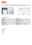
![[Product Name] Service Manual](http://vs1.manualzilla.com/store/data/006035113_1-0289c4c9f962713aa5c1b10dc8f42975-150x150.png)