
1
FXC3024
User Manual
Version 1.0
Oct. 2004
Table of Contents
1.
INTRODUCTION ............................................................................................ 10
1.1
About This Manual.................................................................................................................................10
1.2
Summary of Features .............................................................................................................................10
1.3
Factory Default Settings.........................................................................................................................11
2.
PHYSICAL DESCRIPTION ............................................................................ 13
2.1
Front Panel of L2SW Switch .................................................................................................................13
2.2
L2SW Switch LED Indications..............................................................................................................13
2.3
Rear Panel of L2SW Switch ..................................................................................................................14
2.4
Description of L2SW LEDs ...................................................................................................................14
3.
MANAGEMENT ACCESS .............................................................................. 16
3.1
3.1.1
3.1.2
Management Methods Supported by Various Interfaces ...................................................................16
Serial Port Interface ..................................................................................................................................17
In-band Network Management Interface..................................................................................................17
3.2
3.2.1
3.2.2
3.2.3
3.2.4
Getting Started........................................................................................................................................17
Port Names ...............................................................................................................................................17
Terminal Access Setup .............................................................................................................................17
CLI Syntax Conventions ..........................................................................................................................18
Network Port Access Setup ......................................................................................................................18
4.
WEB MANAGEMENT FUNCTION ................................................................. 19
4.1
Port Status...............................................................................................................................................21
4.2
Port Statistics ..........................................................................................................................................23
4.3
Administrator .........................................................................................................................................24
4.3.1
Stacking ....................................................................................................................................................24
4.3.2
IP Address ................................................................................................................................................25
4.3.3
Switch Setting...........................................................................................................................................27
4.3.3.1 Basic ....................................................................................................................................................27
4.3.3.2 Module Info..........................................................................................................................................28
4.3.3.3 Advanced Settings ................................................................................................................................28
4.3.3.4 Miscellaneous Settings.........................................................................................................................30
4.3.4
Console Port Information .........................................................................................................................31
4.3.5
Trunking ...................................................................................................................................................31
4.3.5.1 Aggregator Settings .............................................................................................................................32
4.3.6
IGMP Snooping and Filter Database ........................................................................................................35
2
4.3.6.1 IGMP Snooping ...................................................................................................................................35
4.3.7
Static MAC Address.................................................................................................................................37
4.3.8
MAC Filtering ..........................................................................................................................................38
4.3.9
VLAN.......................................................................................................................................................38
4.3.9.1 Port Based VLAN................................................................................................................................41
4.3.9.2 802.1Q (Tag based) VLAN .................................................................................................................42
4.3.9.3 VLAN Configuration...........................................................................................................................43
4.3.10 Spanning Tree...........................................................................................................................................46
4.3.10.1
STP (802.1d) Configuration............................................................................................................47
4.3.10.2
RSTP (802.1w) Configuration ........................................................................................................49
4.3.10.3
MSTP Configuration.......................................................................................................................52
4.3.11 Port Sniffer ...............................................................................................................................................55
4.3.12 SNMP .......................................................................................................................................................57
4.3.12.1
SNMP v3 Configuration .................................................................................................................58
4.3.13 Security Manager......................................................................................................................................62
4.3.14 802.1x .......................................................................................................................................................63
4.3.14.1
802.1x Configuration ......................................................................................................................64
4.3.14.2
PerPort Configuration .....................................................................................................................65
4.3.14.3
802.1x Miscellaneous Configuration ..............................................................................................66
4.4
TFTP Update Firmware ........................................................................................................................68
4.5
4.5.1
4.5.2
Configuration Backup............................................................................................................................69
TFTP Backup Configuration ....................................................................................................................69
TFTP Restore Configuration ....................................................................................................................69
4.6
Default Configuration ............................................................................................................................71
4.7
Reboot......................................................................................................................................................71
5.
CONSOLE – MENU LINE............................................................................... 73
5.1
Main Menu ..............................................................................................................................................73
5.2
Switch Static Configuration...................................................................................................................76
5.2.1
Port Configuration ....................................................................................................................................76
5.2.2
Trunk Configuration .................................................................................................................................77
5.2.3
VLAN Configuration................................................................................................................................79
5.2.3.1 VLAN Configure ..................................................................................................................................79
5.2.3.2 Edit / Delete a VLAN Group ................................................................................................................83
5.2.3.3 Groups Sorted Mode............................................................................................................................84
5.2.4
Miscellaneous Configuration....................................................................................................................84
5.2.4.1 MAC Age Interval ................................................................................................................................85
5.2.4.2 Broadcast Storm Filtering ...................................................................................................................85
5.2.4.3 Max Bridge transmit delay bound........................................................................................................86
5.2.4.4 Port Security ........................................................................................................................................87
5.2.4.5 Collisions Retry Forever......................................................................................................................88
5.2.5
Administration Configuration...................................................................................................................88
5.2.5.1 Change Username ...............................................................................................................................89
5.2.5.2 Change Password ................................................................................................................................89
5.2.5.3 Device Information ..............................................................................................................................90
5.2.5.4 IP Configuration..................................................................................................................................90
5.2.6
Port Mirroring Configuration ...................................................................................................................91
5.2.7
Priority Configuration...............................................................................................................................92
5.2.7.1 Port Static Priority ..............................................................................................................................93
3
5.2.7.2 802.1p Priority Configuration .............................................................................................................94
5.2.8
MAC Address Configuration....................................................................................................................94
5.2.8.1 Static MAC Address.............................................................................................................................95
5.2.8.2 Filtering MAC Address........................................................................................................................98
5.3
Protocol Related Configuration...........................................................................................................101
5.3.1
STP .........................................................................................................................................................101
5.3.2
SNMP .....................................................................................................................................................101
5.3.3
GVRP .....................................................................................................................................................101
5.3.4
IGMP ......................................................................................................................................................102
5.3.5
LACP......................................................................................................................................................103
5.3.5.1 Working Port Setting .........................................................................................................................103
5.3.5.2 State Activity ......................................................................................................................................104
5.3.5.3 LACP Status.......................................................................................................................................106
5.3.5.4 LACP trunk group..............................................................................................................................106
5.4
5.4.1
5.4.2
5.4.3
Status and Counters .............................................................................................................................107
Port Status...............................................................................................................................................107
Port Counters ..........................................................................................................................................108
System Information ................................................................................................................................108
5.5
5.5.1
5.5.2
Reboot Switch .......................................................................................................................................109
Default ....................................................................................................................................................110
Restart.....................................................................................................................................................110
5.6
5.6.1
5.6.2
5.6.3
TFTP Update Firmware ......................................................................................................................111
TFTP Update Firmware..........................................................................................................................111
Restore Configure File............................................................................................................................112
Backup Configure File............................................................................................................................113
6.
CLI BASED MANAGEMENT........................................................................ 114
6.1.1
6.1.2
6.1.3
6.1.4
6.1.5
6.1.6
CLI Syntax Conventions ........................................................................................................................115
Login User Setup....................................................................................................................................116
Network Port Access Setup ....................................................................................................................116
Telnet Access Setup ...............................................................................................................................116
Serial Port Setup .....................................................................................................................................117
Inactivity Timeout ..................................................................................................................................117
6.2
Stacking Configuration ........................................................................................................................117
6.3
6.3.1
6.3.2
Port Configuration ...............................................................................................................................118
Display Port Configuration.....................................................................................................................119
Port Configuration Settings ....................................................................................................................120
6.4
MAC Aging ...........................................................................................................................................122
6.5
Static MAC Address.............................................................................................................................122
6.6
MAC Filtering.......................................................................................................................................123
6.7
6.7.1
6.7.2
6.7.3
6.7.4
VLAN.....................................................................................................................................................124
802.1Q VLAN ........................................................................................................................................125
Port VID & Ingress filtering ...................................................................................................................126
Show VLAN...........................................................................................................................................127
GVRP .....................................................................................................................................................129
4
6.8
6.8.1
6.8.2
6.8.3
Spanning Tree Protocol........................................................................................................................130
STP Configuration..................................................................................................................................130
RSTP Configuration ...............................................................................................................................133
MSTP Configuration ..............................................................................................................................134
6.9
Link Aggregation & Trunking Settings..............................................................................................137
6.10
Port Mirroring ......................................................................................................................................139
6.11
Broadcast Storm Filtering ...................................................................................................................140
6.12
IGMP Snooping ....................................................................................................................................140
6.13
802.1X ....................................................................................................................................................141
6.14
Priority ..................................................................................................................................................143
6.15
Switch Settings ......................................................................................................................................144
6.16
Statistics.................................................................................................................................................146
6.17
6.17.1
6.17.2
6.17.3
Management Commands .....................................................................................................................147
User Login Accounts ..............................................................................................................................147
Switch Inventory ....................................................................................................................................147
Network IP Address Configuration ........................................................................................................148
6.18
6.18.1
6.18.2
6.18.3
6.18.4
SNMP.....................................................................................................................................................148
SNMP System Setup ..............................................................................................................................148
SNMP Community setup:.......................................................................................................................149
SNMP Trap Setup...................................................................................................................................150
SNMPv3 Configuration..........................................................................................................................150
6.19
Remote Monitoring ..............................................................................................................................154
6.20
6.20.1
6.20.2
6.20.3
6.20.4
6.20.5
6.20.6
6.20.7
6.20.8
System Utilities......................................................................................................................................155
Management VLAN ...............................................................................................................................155
SNTP Configuration ...............................................................................................................................155
Syslog Configuration..............................................................................................................................156
TFTP Backup or Upload Configuration .................................................................................................156
TFTP restore or download configuration................................................................................................157
TFTP Update Firmware..........................................................................................................................157
Default Configuration.............................................................................................................................158
Reboot ....................................................................................................................................................158
7.
APPENDIX A: TERMS AND ABBREVIATIONS .......................................... 159
5
Table of Figures
FIGURE 2-1 FRONT PANEL OF L2SW SWITCH WITH TWO 1000 BASE TX CARD
FIGURE 2-2 REAR PANEL OF L2SW SWITCH
FIGURE 4-1: LOGIN
FIGURE 4-2: WBI MANAGEMENT INTERFACE
FIGURE 4-3: PORT STATUS
FIGURE 4-4: INDIVIDUAL PORT STATUS
FIGURE 4-5: PORT STATISTICS
FIGURE 4-6: STACKING CONFIGURATION
FIGURE 4-7: IP ADDRESS
FIGURE 4-8: SWITCH SETTINGS/BASIC INFORMATION
FIGURE 4-9: SWITCH SETTINGS/MODULE INFORMATION
FIGURE 4-10: ADVANCED SWITCH SETTINGS
FIGURE 4-11: MISCELLANEOUS SWITCH SETTINGS
FIGURE 4-12: CONSOLE INFORMATION
FIGURE 4-13: TRUNKING
FIGURE 4-14: LACP DISABLED
FIGURE 4-15: STATIC TRUNKING GROUPS
FIGURE 4-16: ACTOR AND PARTNER GROUP
FIGURE 4-17: STATE ACTIVITY
FIGURE 4-18: IGMP SNOOPING
FIGURE 4-19: STATIC MAC ADDRESS
FIGURE 4-20: MAC FILTERING
FIGURE 4-21: VLAN CONFIGURATION
FIGURE 4-22 PORT-BASED VLAN ID
FIGURE 4-23: PORT BASED VLAN
FIGURE 4-24: 802.1Q BASED VLAN
FIGURE 4-25: CREATE VLAN
FIGURE 4-26: ADD PORTS TO VLAN
FIGURE 4-27: CONFIGURE VID
FIGURE 4-28: SPANNING TREE VERSION SELECTION
FIGURE 4-29: SWITCH STP CONFIGURATION SUMMARY
FIGURE 4-30: RSTP CONFIGURATION
FIGURE 4-31: RSTP PORT CONFIGUATION
FIGURE 4-32: RSTP PORT STATUS DISPLAY
FIGURE 4-33: MSTP SWITCH CONFIGURATION
FIGURE 4-34: MST INSTANCE CONFIGURATION
FIGURE 4-35: MSTI CONFIGURATION REPORT
FIGURE 4-36: MST INSTANCE DETAILS
FIGURE 4-37: PORT SNIFFER
FIGURE 4-38:SNMP MANAGEMENT
FIGURE 4-39: COMMUNITY STRINGS
FIGURE 4-40: TRAP MANAGER
FIGURE 4-41: SNMP ENGINE ID CONFIGURATION SCREEN
FIGURE 4-42: VIEWS CONFIGURATION SCREEN
FIGURE 4-43: SNMPV3 GROUP CONFIGURATION
FIGURE 4-44: SNMPV3 USER CONFIGURATION
FIGURE 4-45: SECURITY MANAGER
FIGURE 4-46: ENABLE 802.1X
FIGURE 4-47: 802.1X CONFIGURATION
FIGURE 4-48: 802.1X PERPORT CONFIGURATION
FIGURE 4-49: 802.1X PORT STATUS
6
13
14
19
20
21
22
23
25
26
27
28
29
30
31
32
33
34
34
35
36
37
38
39
40
41
43
44
45
45
48
49
50
51
52
53
53
54
55
56
57
58
58
59
60
61
62
63
64
64
65
66
FIGURE 4-50: 802.1X MISCELLANEOUS CONFIGURATION
FIGURE 4-51: TFTP DOWNLOAD
FIGURE 4-52: CONFIRMATION FOR TFTP UPGRADE
FIGURE 4-53: TFTP BACKUP CONFIGURATION
FIGURE 4-54: TFTP RESTORE CONFIGURATION
FIGURE 4-55: RESET SYSTEM
FIGURE 4-56: REBOOT SYSTEM
FIGURE 5-1: LOGIN FOR CONSOLE
FIGURE 5-2: MAIN MENU FOR CONSOLE
FIGURE 5-3: SWITCH CONFIGURATION
FIGURE 5-4: PORT CONFIGURATION
FIGURE 5-5: TRUNK CONFIGURATION
FIGURE 5-6: VLAN CONFIGURATION
FIGURE 5-7: PORT BASED VLAN
FIGURE 5-8: 802.1Q BASED VLAN
FIGURE 5-9: CREATE PORT BASED VLAN
FIGURE 5-10: CREATE 802.1Q BASED VLAN
FIGURE 5-11: SELECT A VLAN FOR EDITING
FIGURE 5-12: EDIT/DELETE SELECTED VLAN
FIGURE 5-13: GROUP SORTED VLAN
FIGURE 5-14: MISCELLANEOUS CONFIGURATION
FIGURE 5-15: MAC AGE INTERVAL
FIGURE 5-16: BROADCAST STORM FILTERING
FIGURE 5-17: MAXIMUM BRIDGE TRANSMIT DELAY BOUND
FIGURE 5-18: PORT SECURITY
FIGURE 5-19: COLLISIONS RETRY FOREVER
FIGURE 5-20: DEVICE CONFIGURATION
FIGURE 5-21: USER NAME CONFIGURATION
FIGURE 5-22: PASSWORD CONFIGURATION
FIGURE 5-23: DEVICE INFORMATION
FIGURE 5-24: IP CONFIGURATION
FIGURE 5-25: PORT MIRRORING
FIGURE 5-26: PRIORITY CONFIGURATION
FIGURE 5-27: PORT PRIORITY
FIGURE 5-28: 802.1P PRIORITY CONFIGURATION
FIGURE 5-29: MAC ADDRESS CONFIGURATION
FIGURE 5-30: STATIC MAC ADDRESS CONFIGURATION
FIGURE 5-31: ADD STATIC MAC ADDRESS
FIGURE 5-32: SELECT MAC ADDRESS
FIGURE 5-33: EDIT STATIC MAC ADDRESS
FIGURE 5-34: DELETE STATIC MAC ADDRESS
FIGURE 5-35: FILTER MAC ADDRESS
FIGURE 5-36: ADD MAC ADDRESS
FIGURE 5-37: FILTER MAC ADDRESS CONFIGURATION
FIGURE 5-38: EDIT FILTER MAC ADDRESS
FIGURE 5-39: DELETE SELECTED MAC ADDRESS
FIGURE 5-40: GVRP CONFIGURATION
FIGURE 5-41: IGMP CONFIGURATION
FIGURE 5-42: LACP CONFIGURATION
FIGURE 5-43: LACP GROUP CONFIGURATION
FIGURE 5-44: LACP PORT STATE ACTIVE CONFIGURATION
FIGURE 5-45: LACP STATIC TRUNKING GROUP
FIGURE 5-46: LACP GROUP STATUS
FIGURE 5-47: STATUS AND COUNTERS
FIGURE 5-48: PORT STATUS
FIGURE 5-49: PORT COUNTERS
7
66
68
68
69
69
71
72
73
74
76
76
78
79
79
80
81
82
83
83
84
85
85
86
86
87
88
89
89
90
90
91
92
93
93
94
95
95
96
97
97
98
98
99
99
100
100
102
102
103
103
104
106
106
107
107
108
FIGURE 5-50: SYSTEM INFORMATION
FIGURE 5-51: RESTART CONFIGURATION
FIGURE 5-52: DEFAULT SETTING
FIGURE 5-53: TFTP UPDATE FIRMWARE CONFIGURATION
FIGURE 5-54: EDIT TFTP UPDATE FIRMWARE
FIGURE 5-55: RESTORE CONFIGURATION FILE
FIGURE 5-56: BACKUP CONFIGURATION FILE
FIGURE 6-1 LOGIN PROMPT
FIGURE 6-2 DISPLAYS STACK
FIGURE 6-3: PORT STATUS DISPLAY
FIGURE 6-4 MAC TABLE AGING TIME
FIGURE 6-5 SHOW STATIC MAC ADDRESS ENTRIES
FIGURE 6-6: DYNAMICALLY LEARNT MAC ADDRESSES DISPLAY
FIGURE 6-7 DISPLAYS MAC FILTER ENTRIES
FIGURE 6-8 DISPLAY VLAN SUMMARY
FIGURE 6-9 DISPLAY VLAN DETAILS FOR SELECTED VLAN
FIGURE 6-10 SHOW VLAN PORT
FIGURE 6-11: GVRP INFORMATION DISPLAY
FIGURE 6-12 DISPLAYS SWITCH STP SETTINGS IN SUMMARY FORM
FIGURE 6-13: DISPLAY SWITCH SETTINGS IN DETAILED FORM
FIGURE 6-14 DISPLAYS PORT STP SETTINGS IN SUMMAY FORM
FIGURE 6-15: DISPLAY STP PORT SETTINGS IN DETAILED FORM
FIGURE 6-16: RSTP PORT CONFIGURATION STATUS DISPLAY
FIGURE 6-17: MST SWITCH CONFIGURATION DISPLAY IN SUMMARY FORMAT
FIGURE 6-18: MST SWITCH CONFIGURATION DISPLAY IN DETAILED FORMAT
FIGURE 6-19: MST INSTANCE DETAILS
FIGURE 6-20: SPANNING TREE PORT INFORMATION DISPLAY
FIGURE 6-21 DISPLAY TRUNK SUMMARY
FIGURE 6-22 DISPLAYS SELECTED TRUNK DETAILS
FIGURE 6-23 SHOW PORT MIRRORING
FIGURE 6-24 DISPLAYS BROADCAST STORM SETTINGS
FIGURE 6-25 DISPLAYS IGMP SNOOPING SETTINGS
FIGURE 6-26 DISPLAYS RADIUS SETTINGS
FIGURE 6-27 DISPLAYS DOT1X SWITCH SETTINGS
FIGURE 6-28 DISPLAYS DOT1X PORT CONTROL
FIGURE 6-29 DISPLAYS 802.1P PRIORITY SETTINGS
FIGURE 6-30: HARDWARE TABLE SIZE CONFIGURATION COMMAND
FIGURE 6-31 DISPLAYS SWITCH SETTINGS
FIGURE 6-32 DISPLAYS PORT STATISTICS
FIGURE 6-33 DISPLAY INVENTROY
FIGURE 6-34 DISPLAYS NETWORK SETTINGS
FIGURE 6-35 DISPLAYS SNMP SYSTEM SETTINGS
FIGURE 6-36 DISPLAYS SNMP COMMUNITY SETTINGS
FIGURE 6-37 DISPLAYS SNMP TRAP SETTINGS
FIGURE 6-38: SNMP SYSTEM CONFIGURATION
FIGURE 6-39: SNMP MIB VIEWS
FIGURE 6-40: SNMPV2 GROUP CONFIGURATION
FIGURE 6-41: SNMP USER CONFIGURATION
FIGURE 6-42: SNTP CONFIGURATION
FIGURE 6-43 DISPLAYS UPLOAD CONFIGURATION TO TFTP SERVER
FIGURE 6-44 DISPLAYS CONFIGURATION DOWN LOAD TO SYSTEM
FIGURE 6-45 DISPLAYS IMAGE DOWNLOAD
FIGURE 6-46 RESET SWITCH CONFIGURATION TO FACTORY DEFAULT
FIGURE 6-47 DISPLAYS SYSTEM REBOOT OPERATION
8
109
110
110
111
111
112
113
115
118
120
122
123
123
124
128
128
129
130
132
132
132
133
134
136
136
137
137
138
139
140
140
141
142
143
143
144
146
146
147
147
148
149
150
150
151
152
153
153
156
156
157
157
158
158
9
1. Introduction
1.1
About This Manual
The guide is intended for network administrators who are responsible for installing, provisioning and
managing L2SW layer 2 switch running software version R2.2 or higher. It assumes a basic working
knowledge of the following:
1.2
•
Local area networks (LANs)
•
Ethernet concepts
•
Ethernet switching and bridging concepts
•
Internet Protocol (IP) concepts
Summary of Features
•
10/100Base TX half and Full Duplex
•
1000BaseT, SX and LX full Duplex
•
802.1D MAC Bridge
•
802.1w Rapid Spanning Tree Protocol (RSTP)
•
802.1s Multiple Spanning Tree Protocol (MSTP)
•
Virtual LANs (VLAN) 802.1Q
•
GVRP
•
Spanning Tree Protocol (STP)
•
802.1p Priority Queuing
•
802.1x Network Port Security
•
802.3x Flow Control
•
802.3ad Link Aggregation
•
Port Mirroring
•
Broadcast Storm Recovery (BSR)
•
IGMP Snooping
•
Bootstrap Protocol (BOOTP) and Dynamic Host Configuration/Control Protocol
(DHCP) clients for management interface
•
Trivial File Transfer Protocol (TFTP) client for management interfaces
•
User Interfaces
10
¾ Console Menu Line Interface (CMLI)1
¾ Command Line Interface (CLI)
¾ Web Based Interface (WBI)
•
Simple Network Management Protocol (SNMP)
¾ SNMP- v1
¾ SNMP-v2c and SNMPv3
1.3
•
Simplified Remote Monitoring (RMON) I sections 1, 2, 3, and 9
•
Simple Network Timing Protocol (SNTP)
•
Syslog
Factory Default Settings
The L2SW products are factory provisioned with the following default settings:
• User Account admin
•
Password representative)
(contact your sales
•
Telnet -
Enabled
•
System IP Address -
192.168.1.1
•
Subnet Mask -
255.255.255.0
•
Default Gateway IP Address -
192.168.1.2
•
Broadcast Storm filtering -
Disabled
•
802.3x Flow Control Mode
Enabled
•
802.1x Network Port Security
Disabled
•
LACP Mode -
Disabled
•
Port Mirroring Mode -
Disabled
•
STP Port State -
Disabled
•
Port Mirroring -
Disabled
•
VLAN traffic -
untagged
•
Ingress Filtering -
Disabled
•
GVRP
Disabled
•
IGMP Snooping
•
BOOTP/DHCP Admin Mode -
Disabled
•
SNTP
Disabled
•
Syslog
Disabled
-
Disabled
11
For all acronyms used in the manual see Appendix A
12
2. Physical Description
This chapter explains the hardware features of the L2SW Ethernet Smart Switch.
2.1
Front Panel of L2SW Switch
L2SW switch is designed for efficient use, with front panel access to the Fast Ethernet (10/100Base T)
ports and two slots for user installable plug-in modules for uplink connection. The front panel also
includes status LEDs for all the ports including uplink ports.
•
24 x 10/100 Mbps Fast Ethernet ports.
•
2 plug-in slots for uplink connection. The following plug-in cards are supported in
L2SW.
¾ 10/100/1000 Mbps T card. It supports auto-negotiation and can operate in
master/slave clock modes
¾ 100 Mbps (100BaseFX) card. This card is available with SC.
¾ 1000 Mbps SFP card.
Figure 2-1 Front Panel of L2SW Switch with two 1000 Base TX card
2.2
L2SW Switch LED Indications
•
24 pairs of LEDs for 24 Fast Ethernet ports
¾ Upper LED – link status (up/down) and port activity
¾ Lower LED – ON- 100 Mbps, OFF- 10 Mbps settings
•
2 LEDs for each plug-in feature card ports
¾ When a 1000Base feature card is used:
Upper LED - link status (up/down) and port activity
Lower LED - ON 1000Mbps, OFF - less than 1000 Mbps
¾ When a 100Base FX feature card is used:
Upper LED - link status (up/down) and port Activity
13
Lower LED - ON - 100 Mbps
•
3 LEDs for Power Status Indicator (located on left corner)
¾ Upper (PWR)- Power on status
¾ Middle(BSALERT)- Broadcast Storm Alert
¾ Lower(FLT)- Fault
See section 2.4 for a description of the various LEDs in L2SW switch.
2.3
Rear Panel of L2SW Switch
The rear panel of L2SW switch has the following connectors on its rear panel as illustrated in Figure
2-2.
•
AC power connector (AC power cord comes standard with the unit) – The L2SW switch
operates with AC power input from 100VAC to 240VAC with a frequency range of 50 to 60
Hz.
•
RS-232 connector – Console port for local management
Console Port
Figure 2-2 Rear Panel of L2SW Switch
2.4
Description of L2SW LEDs
The L2SW switch’s port LEDs allow the user to identify:
•
Status of ports
•
Data transmission or receive activity
•
Link speed (10/100/1000Mbps)
LED-ON
(green/Amber)
L2SW Base Board (24 10/100Mbps
ports)
L2SW 10/100 port Upper LED
Link-UP
14
LED-OFF
Link-Down
Blinking
RX/TX Activity
L2SW 10/100 port Lower LED
L2SW 1000BaseT card
10/100/1000 Mbps Port Upper LED
10/100/1000 Mbps Port Lower LED
L2SW SX or LX card
1000 Mbps Fiber port Upper LED
1000 Mbps Fiber Port Lower LED
L2SW 100BaseFX card
100 Mbps Fiber port Upper LED
100 Mbps Fiber port Lower LED
LED-ON
(green/Amber)
100 Mbps (Green)
LED-OFF
10 Mbps
N/A
Link-UP
1000 Mbps (Amber)
Link-Down
10/100 Mbps
RX/TX Activity
N/A
Link-UP
1000 Mbps (Amber)
Link-Down
N/A
RX/TX Activity
N/A
Link-UP
100 Mbps (Amber)
Link-Down
N/A
RX/TX Activity
N/A
Table 2-1: L2SW LED Indications
15
Blinking
3. Management Access
L2SW switch provides the network administrator with a set of comprehensive management functions
for configuration of the switch. The network administrator has a choice of four types of management
interfaces:
•
CMLI
•
CLI
•
WBI
•
SNMP
CMLI: Console Menu Line Interface (CMLI) is one of the management interfaces supported by
L2SW. The CMLI provides a menu-oriented interface for the user to configure and monitor the
L2SW switch. Users can access this interface only via serial port. CMLI interface is being
discontinued. Therefore, any new features implemented in L2SW will not be supported using CMLI.
CLI: CLI commands allow the user to configure various L2SW switch features like Spanning Tree
Protocol, VLAN, Mac filter, Port security, 802.1x etc and also perform a set of maintenance related
functions like users maintenance, log traps, telnet sessions, etc. The L2SW switch can be managed
using CLI commands over the dedicated serial interface or via a telnet session.
WBI: L2SW switch can also be managed using a graphical interface using Web browser. A flexible
and consistent set of screens, allow the user to configure and manage the resources available on the
L2SW switch. In addition, real time events such as alarms and statistics can be monitored using the
WBI. Some of the new features such as SNTP, Syslog, Per-port GVRP configuration and
Management VLAN are not currently supported through WBI. These features will be supported in a
future release of L2SW switch.
SNMP based Management: L2SW switch can also be managed using an external SNMP manager.
L2SW switch supports standard MIBs and some proprietary MIBs (enterprise specific extensions to
manage the additional features supported by the switch). Any external SNMP based manager, like
HP-Openview can be used to configure and manage the L2SW switch. The SNMP agent in the L2SW
switch also implements trap functionality so that the SNMP Manager can receive traps from the
switch.
Management access methods of L2SW switch enable the network administrator to locally/remotely
configure, manage and control using the following access interfaces:
•
Serial Port
•
Ethernet Line Ports
The Serial port is referred to as out-of-band interfaces, while the Ethernet ports are referred to as inband management interfaces. While out-of-band interfaces are dedicated for management of L2SW
switch, in-band interfaces are used to carry both the user’s network traffic as well as the management
traffic of the L2SW switch.
3.1
Management Methods Supported by Various Interfaces
16
3.1.1 Serial Port Interface
•
CMLI
•
CLI
3.1.2 In-band Network Management Interface
3.2
•
CLI
•
WBI
•
SNMP
Getting Started
The following sections describe setting up of management stations for managing the L2SW switch.
3.2.1 Port Names
The term port refers to a physical Fast Ethernet port, a port on the user installable plug-in module
card, or a logical trunk in the L2SW switch. Each port is referred to using the following naming
convention:
<slot-number>.<port-number>
where:
represents the port type and <port number> represents the number of the physical
port within the selected port type. Slot 0 denotes the fixed 24 x 10/100 Fast Ethernet ports, slot 1
represents the user installable plug-in module card, and slot 2 represents the logical trunk port.
<slot-number>
is the number assigned to the port. The range and assignment of port numbers varies
by the slot type. The assignment of port numbers by slot number is shown in the following table:
<port-number>
Slot Number
0 (24 x 10/100 FE)
1 (plug-in module card)
2 (trunk port)
Port Number Assignment
(Left to Right)
Upper level: 1 ~ 12
Lower level: 13-24
12
1234567
In this document, some alternative notations are also used to refer to the port numbers:
•
PORT#. Refers to physical ports. For example, PORT8 is equivalent to 0.8, and PORT25 and
26 refer to 1.1 and 1.2 respectively.
•
TRUNK#.
Refers to logical trunk ports. For example, TRUNK3 is equivalent to 2.3.
3.2.2 Terminal Access Setup
17
L2SW switch has a RS-232 serial interface located on the rear side of the switch. Any terminal with
VT100 terminal emulation capabilities can be connected to this port using a standard RS-232 serial
cable. The following terminal settings have to be configured for the serial communication to work
properly:
•
Baud Rate
= 19200
•
Data Bits
=8
•
Parity
•
Stop Bits
•
Flow Control
= none
=1
= none
3.2.3 CLI Syntax Conventions
Command
Description
Text displayed in Bitstream Vera Sans font after the
L2SW> prompt must be typed exactly as shown. Following the
syntax of a command, an example usage of the command is
shown. Output of the command is shown either in Italics or as
image of the screen displaying the actual results.
<parameter>
The <> angle brackets indicates that the parameter is required
for executing the command
[parameter]
The [] square brackets indicates that the parameter is optional
choice1 | choice2 The | indicate that only one of the parameter should be entered
Ipaddr
This parameter is a valid IP address of four decimal bytes
(separated by .), each byte ranging from 0 to 255. The default
IP is 0.0.0.0
Macaddr
The MAC address format is six hexadecimal numbers
separated by colons, for e.g., 0:20:10:32:0e:40
slot.port
This parameter denotes a valid slot number and a valid port
number. For example 0.1 represents slot 0 port 1
Command Name and
parameters
3.2.4 Network Port Access Setup
Any of the in-band line ports can be used for management of the L2SW switch.
If DHCP is used to assign IP address for the switch, use the following command to enable DHCP.
L2SW> config network protocol <none/dhcp>
L2SW> config network protocol dhcp
18
4. Web Management Function
For management of L2SW via WBI, a Web browser is required. Microsoft Internet Explorer (version
5.0 or higher) is recommended.
If you need to change IP address for the first time, you can use console mode to modify the following
default parameters:
IP Address:
172.30.40.145
Subnet Mask:
255.255.255.0
Default Gateway:
172.30.40.2
Assuming that the IP address assigned to the in-band port of the L2SW switch is set to 172.30.40.145,
you can use browser to connect to the switch by typing the URL.
After connection is established with the L2SW switch, the browser will display the login screen as
shown below:
Figure 4-1: Login
Upon entering a valid user name and password2, WBI management interface screen will be presented
to the user as shown below:
2
Contact technical support or sales representative for the default password
19
Figure 4-2: WBI Management Interface
The navigation tree displayed on the left side of the browser window should be used for choosing
appropriate configuration screens. It is organized with the folders for configuration of different
features supported by L2SW switch.
20
4.1
Port Status
Port Status page displays interface details such as speed, duplex mode, flow control, priority and
security information for each port.
Figure 4-3: Port Status
State: Port state information is displayed under two columns: Config and Actual. Configured and
actual port state information, are displayed as On or Off. Note that the port status and port statistics
pages are automatically updated after every 5 seconds.
Link Status:
Link status information is displayed as Up or Down. If the link is established between
with peering port, the link status information is displayed as Up. Otherwise, it is displayed as Down.
Auto Negotiation:
One of the following three values will be displayed as auto-negotiation mode:
•
Auto
•
Force
•
Nway-force
21
Speed: Display Speed for port 1- 24 is displayed as 10 Mbps or 100Mbps and speed for Port 25-26 is
displayed as 10, 100 or 1000Mbps.
Duplex status:
Full (full-dulex) or Half (half-duplex) mode.
Flow Control:
Display the flow control status as On or Off. The flow control status is displayed
under the columns Full and Half.
Full:
Send/Process PAUSE frames to exercise flow control
Half: Use
Rate Control:
Jabber to exercise flow control in half-duplex mode
Display the rate control setting of the Ingress and Egress side of each port.
Ingr:
Display the effective ingress rate for the port
Egr:
Display the effective egress rate for the port
Priority:
Display the port’s static priority as High or Low or Disable.
Port Security:
Security status of a port is displayed as On (Enabled) and Off (Disabled)
Values displayed under the column Config are the values configured by the user and the values displayed
under the column Actual are the values derived as a result of negotiation with the corresponding partner
of a port.
User can see an individual port status by clicking on any of the ports in L2SW image displayed on top of the page.
The following web page is used to display status of the selected port.
Figure 4-4: Individual Port Status
22
4.2
Port Statistics
Port Statistics page displays information such as interface state, link status, transmission and
reception statistics for each port.
Figure 4-5: Port Statistics
Use Reset button to clear the port statistics.
23
4.3
Administrator
This link on the navigation tree allows the user to configure the following features:
•
Stacking
•
IP address
•
Switch settings
•
Console port information
•
Port controls
•
Trunking
•
Filter database
•
VLAN configuration
•
Spanning tree
•
Port Sniffer
•
SNMP
•
Security Manager
•
TFTP Update Firmware
•
Configuration Backup
•
Reset System
•
Reboot
4.3.1 Stacking
Stacking capability allows the user to manage a group of up to 8 switches from a single management
point. This page provides stack configuration to set stacking parameters on the master unit and stack
status to view the system MAC address, stack port, software version and status for each unit in the
stack when stacking is enabled. And on the left side of page, user can access slave units by clicking
unit ID drop down list.
To enable stacking feature, configure an IP address on master unit and open this page, select Enable
option in Admin Mode tab and click on Apply. To disable stacking feature, select Disable option
in Admin Mode tab and click on Apply.
To configure the number of switches that participate in the stacking configuration, enter a decimal
number between 2 and 8, then click on Apply. Default value is 8. Stacking maximum units
configuration should match with the number of units currently connected via stack up link ports and
stack down link ports.
To view the stacking status, check stack status part on the page.
To access slave units in the stack, click unit ID drop down list, choose the unit ID and click on select
24
tab.
Figure 4-6: Stacking Configuration
4.3.2 IP Address
25
Figure 4-7: IP Address
IP Address for the switch can be configured either statically or obtained dynamically from a DHCP
server. To automatically obtain the IP address using DHCP, select Enable option in DHCP tab and
click on Apply.
To statically configure the IP address, select Disable in DHCP tab; enter the IP address, subnet mask
and default gateway parameters and click on Apply.
26
4.3.3 Switch Setting
4.3.3.1
Basic
Various factory assigned parameters of the switch, such as, MAC address, Firmware/ASIC version,
Serial Number etc. are displayed in this page.
Figure 4-8: Switch Settings/Basic Information
Description:
Displays name of device
MAC Address:
Displays unique hardware address assigned by manufacturer
(default)
Firmware Version:
Displays switch’s firmware version.
ASIC Version:
Displays switch’s Hardware version.
PCBA version:
Displays board number.
27
Displays serial number assigned by manufacturer.
Serial number:
4.3.3.2
Module Info
Replaceable feature cards are displayed in this page.
Figure 4-9: Switch Settings/Module Information
Type and description of the plug-in module cards are displayed in this page.
4.3.3.3
Advanced Settings
Advanced Settings of the switch such as MAC Address Age-out time, Broadcast Storm Filter, 802.1p
Priority are displayed in this Page. User can change the values of these settings (e.g., Age-out time)
by editing the values displayed inside the box.
28
Figure 4-10: Advanced Switch Settings
MAC Address Age-out Time:
Type the number of seconds that an inactive MAC address remains in
the switch's address table. The valid range is 10 ~765 seconds. Default is 300 seconds.
Limit the packets queuing time in switch. If enabled,
the packets queued which exceed the delay bound setting will be dropped. This valid values are 1sec,
2 sec, 4 sec and off.
Max bridge transmit delay bound control:
Enable Low Queue Delay Bound:
Limit the low priority packets queuing time in switch.
If the low priority packet queued up in switch exceed Max Delay Time, it will be dropped. The valid
range is 1~255 ms.
NOTE: Enable Max bridge transit delay bound control before enabling Low Queue Delay
because this parameter is valid only when Max bridge transit delay bound control is
enabled.
Bound,
Broadcast Storm Filter: To configure broadcast storm control, enable it and set the upper
threshold for individual ports. The threshold is the percentage of the port's total bandwidth used by
29
broadcast traffic. When broadcast traffic for a port rises above the threshold you set, broadcast storm
control becomes active. The valid threshold value are 5%, 10%, 15%, 20%, 25% and off.
Priority Queue Service Settings: Priority queue settings part of the screen allows the user to
choose processing method for packets queued for a port.
First Come First Service:
All High before Low:
The sequence of packets sent is dependent on order of arrival.
The high priority packets are sent before low priority packets.
WRR:
Weighted Round Robin. Select the preference given to packets in the switch's high-priority and
low priority queue.
These options represent the number of high priority packets sent before one low priority packet is sent.
For example, 5 High: 2 Low means that the switch sends 5 high priority packets before sending 2 low
priority packet.
QOS Policy:
4.3.3.4
High Priority Levels: 0~7 priority level can map to high or low queue.
Miscellaneous Settings
Other features essential to the switch such as 802.1x protocol, Hash Algorithm, IFG compensation are
displayed on this page.
Figure 4-11: Miscellaneous Switch Settings
Collisions Retry Forever:
Enable/disable collisions retry forever.
30
Hash Algorithm: CRC-hash/Direct-map hash algorithm. The default setting should be changed only
under special circumstances.
Enable/disable IFG Compensation3. The default setting should be changed only
under special circumstances.
IFG Compensation:
802.1x protocol:
Enable/disable 802.1x protocol.
4.3.4 Console Port Information
Console is a standard UART interface to communicate with Serial Port. Various parameters, such as
Baudrate, Parity Check, Flow control etc are displayed in this page.
Figure 4-12: Console Information
Windows hyper-terminal program can be used to connect to the switch. Make sure the baud rate and
stop bit settings on the Windows hyper-terminal match the following settings for the console port.
•
Baudrate:
•
Data bits:
•
Parity:
•
Stop bits:
•
Flow control:
19200
8
none
1
none
4.3.5 Trunking
L2SW supports both static and dynamic trunking using the Link Aggregation Control Protocol
3
For an brief explanation on IFG, read section 6.15.
31
(LACP). LACP provides a standardized means for exchanging information between Partner Systems
on a link to allow their Link Aggregation Control instances to reach agreement on the identity of the
Link Aggregation Group to which the link belongs, move the link to that Link Aggregation Group,
and enable its transmission and reception functions in an orderly manner. Link aggregation lets you
group up to eight consecutive ports into a single dedicated connection. This feature can expand
bandwidth to a device on the network by combining two or more lower speed ports.
LACP operation requires full-duplex mode, for more detail information refer to IEEE
802.3ad standard.
4.3.5.1
Aggregator Settings
This page is used to create a link aggregation across two or more ports.
Figure 4-13: Trunking
To create a link aggregation group with two or more ports, the following parameters are used:
System Priority: This value is used to identify the active LACP. The switch with the lowest value
has the highest priority and is selected as the active LACP.
Group ID:
Seven trunk groups are available for configuration. Choose the "group id" and click "Get"
32
to configure a Link aggregation group.
LACP:
If enabled, the group is LACP static trunking group. If disabled, the group is local static
trunking group. All ports support LACP dynamic trunking group. If the switch is connected to
another device that also supports LACP, the LACP dynamic trunking group will be created
automatically.
Work ports: A maximum of four ports can be aggregated within a trunking group. If the number of
ports configured to be part of a LACP static trunking group exceeds the maximum number, the excess
ports are moved to a standby state and would be able to join the trunking group, if any of the working
ports in the group fails. If the local static trunking group is used then the number of group member
ports must be as same as the working ports.
Select the ports to join the trunking group by selecting the ports from the ports list. A maximum of
four ports can be aggregated within a trunking group.
If LACP is enabled, you can configure LACP Active/Passive status in each port on State Activity
page. To complete the LACP configuration, click the Apply button.
4.3.5.1.1
Trunking Configuration
This page displays the current LACP status. If LACP is enabled, the group is LACP trunking group.
Otherwise, the group is Local static trunking group.
The following are the various scenarios of LACP status:
Scenario 1: LACP is disabled and there are no active links.
Figure 4-14: LACP disabled
Scenario 2: LACP Enabled with no active links
33
Figure 4-15: Static Trunking Groups
Scenario 3: LACP is enabled with active links
Figure 4-16: Actor and Partner Group
The following page displays the state of each LACP and it indicates whether that port is in active or
passive state.
34
Figure 4-17: State Activity
(select): The switch automatically sends LACP protocol packets through this port.
Active
(no select): The switch does not automatically send LACP protocol packets through this
port, and responds only if it receives LACP protocol packets from the peer device.
Passive
A link having either two active LACP ports or one active port can perform dynamic LACP trunking.
Switches attached to a link with two passive LACP ports will not perform dynamic LACP trunking
because both switches are waiting for LACP protocol packet from its peer.
4.3.6 IGMP Snooping and Filter Database
The L2SW supports IP multicast, user can enable/disable IGMP Snooping, Static MAC Addresses
and MAC filtering using this page.
4.3.6.1
IGMP Snooping
35
Figure 4-18: IGMP Snooping
The Internet Group Management Protocol (IGMP) is a multicast protocol of the Internet Protocol (IP)
suite. Multicast traffic is propagated through the network using switches, routers, and hosts that
support IGMP and other multicast protocols. Enabling IGMP snooping allows the ports to detect
IGMP queries and report packets and manage IP multicast traffic through the switch. IGMP has three
fundamental types of messages:
The IGMP query mode can be enabled or disabled. If IGMP query mode is disabled, switch will
perform passive snooping of IGMP Query/Report messages passing thru the switch. If enabled, the
switch will perform IGMP query functions if there is no other device in the VLAN such as a multicast
router is available to perform query functions.
Message
Query
Description
A message sent from the querier (IGMP router or switch) asking for a response from each host
belonging to the multicast group. If IGMP query mode is
disabled, switch will perform passive snooping of IGMP Query/Report messages passing thru
the switch. If enabled, the switch will perform IGMP query functions if there is no other
device in the VLAN,such as a multicast router is available to perform query functions.
Report
A message sent by a host to the querier to indicate that the host wants to be or is a
member of a given group indicated in the report message.
Leave Group
A message sent by a host to the querier to indicate that the host has quit to be a
member of a specific multicast group.
36
Table 4-1: IGMP Snooping
4.3.7 Static MAC Address
Static MAC address remains in the switch's address table, regardless of whether the device is
physically connected to the switch. This saves the switch from having to re-learn a device's MAC
address when the disconnected or powered-off device is active on the network again.
This page enables the user to add/delete a MAC address.
Figure 4-19: Static MAC Address
To add a Static MAC Address, execute the following steps:
1. From the main menu, click administrator Æ Filter DatabaseÆ Static MAC Address.
2. In the MAC address box, enter the destination MAC address of the frames which should be
forwarded by the switch to a fixed port (also defined in this screen)
3. In the Port Number box, enter a port number.
4. If tag-based (IEEE 802.1Q) VLANs are set up on the switch, VLAN IDs are associated with
individual VLANs. Type the VID (tag-based VLANs) to associate the VLAN with the MAC
address entered earlier.
Click Add button
37
4.3.8 MAC Filtering
MAC address filtering allows the switch to drop unwanted traffic. Traffic is filtered based on the
destination addresses. For example, if network is congested because of heavy bursts of traffic from
one particular MAC address, using this page, user can filter all traffic transmitted from or to that
MAC address. This type of filtering would enable the network administrator to restore network traffic
flow while troubleshooting the problem.
Figure 4-20: MAC Filtering
To add MAC filter, use the following procedure:
1. In the MAC Address box, enter the MAC address that needs to be filtered.
2. If tag-based (802.1Q) VLANs are set up on the switch, type the VID in the VLAN ID box to
associate with the MAC address defined earlier
3. Click the Add button.
4. If a MAC address filter has to be deleted, enter the MAC address to be deleted and then click the
Delete button.
4.3.9 VLAN
A Virtual LAN (VLAN) is a logical network grouping that limits the broadcast domain. It allows the
user to isolate network traffic so that members of a VLAN receive traffic, only from the members of
the same VLAN. Basically, creating a VLAN is logically equivalent of connecting a group of network
devices to a separate Layer 2 switch even though all the network devices are still plugged into the
same switch physically.
The L2SW supports port-based, 802.1Q (tagged-based) and protocol-based VLAN. In the default
38
configuration, VLAN support is disabled.
Figure 4-21: VLAN configuration
If VLAN mode is changed, you have to reboot the switch to make the change effective.
To enable GVRP mode, Click on the box marked Enable GVRP Protocol4.
In Port-based VLAN, packets can be exchanged only between devices attached to the ports that are
members of the same VLAN group. If the port-based VLAN is enabled, the VLAN-tagging is
ignored.
4
It is recommended that GVRP configuration is done only through CLI interface since per-port GVRP
configuration is not currently supported through WBI or CMLI.
39
Figure 4-22 Port-based VLAN ID
Tagged-based VLAN is an IEEE 802.1Q standard. It is possible to create a VLAN across devices
from different switch venders using this standard. IEEE 802.1Q VLAN inserts a “tag” into the
Ethernet frames, which contains the VLAN identifier (VID).
In order for an end station to send packets to different VLANs, it has to be either capable of tagging
packets with VLAN ID or get attached to a VLAN-aware bridge/switch that is capable of classifying
and tagging the packets with different VLAN ID based on not only default Port-based VLAN ID
(PVID) but also other information about the packet, such as the protocol.
L2SW supports protocol-based VLAN classification and tagging based on layer 2 packet formats
used by selected popular protocols, such as Novell IPX and AppleTalk’s EtherTalk.
Port VLAN ID (PVID) defines the VLAN ID that will be assigned to untagged frames received from
a given port. For example, if port 10's PVID is 100, all untagged packets received on port 10 will
belong to VLAN 100. The default PVID setting for all ports is VID 1.
This feature is useful for accommodating devices that user wants to participate in the VLAN but that
don't support tagging. Only one untagged VLAN is allowed per port. In other words, there can be
only one PVID per port.
Ingress Filtering: Ingress filtering feature is used to filter tagged frames received through a port with
VLAN ID that doesn’t match any of the VLANs in which the port participate in. Disabling this
setting will cause all frames to be forwarded, regardless of the port's VLAN setting.
GVRP (GARP VLAN Registration Protocol) allows automatic VLAN configuration between the
switch and nodes. If the switch is connected to a device with GVRP enabled, the device can send a
GVRP request using the VID of a VLAN defined on the switch, and it will automatically add that
device to the existing VLAN.
40
4.3.9.1
Port Based VLAN
In Port based VLAN, traffic is forwarded to the member ports of the same VLAN group. Use the
following Port-based VLAN configuration web page, to configure Port based VLAN.
Figure 4-23: Port based VLAN
To create a port based VLAN use the following procedure:
1. Click Add to create a new VLAN group.
2. Enter the VLAN name, group ID and select the members for the new VLAN.
3. Click Apply button.
4. If there are many groups that span over the limit of one page user can click the “NextPage” to
view other VLAN groups.
NOTE: If the trunk groups exist, user can see it (e.g.,:TRK1,TRK2…..) in select menu of ports.
Users can configure Trunk ports to be a member of a VLAN.
PVIDs cannot be assigned arbitrarily. Instead, all the PVIDs must take on values within the same
PVID set. The following list depicts the relation between the PVID sets and value of PVID.
¾ PVID Set 0. PVID range: 0 - 255
41
¾ PVID Set 1. PVID range: 256 - 511
¾ PVID Set 2. PVID range: 512 - 767
¾ PVID Set 3. PVID range: 768 - 1023
¾ PVID Set 4. PVID range: 1024 - 1279
¾ PVID Set 5. PVID range: 1280 - 1535
¾ PVID Set 6. PVID range: 1536 - 1791
¾ PVID Set 7. PVID range: 1792 - 2047
¾ PVID Set 8. PVID range: 2048 - 2303
¾ PVID Set 9. PVID range: 2304 - 2559
¾ PVID Set 10. PVID range: 2560 - 2815
¾ PVID Set 11. PVID range: 2816 - 3071
¾ PVID Set 12. PVID range: 3072 - 3327
¾ PVID Set 13. PVID range: 3328 - 3583
¾ PVID Set 14. PVID range: 3584 - 3840
¾ PVID Set 15. PVID range: 3841 – 4095
4.3.9.2
802.1Q (Tag based) VLAN
Tag-based VLANs are based on IEEE 802.1Q specifications. Traffic is forwarded to VLAN member
ports based on identifying VLAN tags in data packets.
User can use the following web page to configure 802.1Q VLAN
42
Figure 4-24: 802.1Q based VLAN
To configure a tag-based VLAN, use the following procedure:
1.
2.
3.
4.
5.
6.
7.
8.
Create a VLAN and add tagged member ports to it.
From the main menu, click VLAN Configuration then click 802.1Q VLAN Operation Mode.
Click Add button.
Type a name for the new VLAN.
Type a VID (between 2-4094). The default value is 1.
Select protocol VLAN. The default value is None.
From the Available ports box, select ports to add to the switch and click Add.
Click Next.
By adding ports to the 802.1Q VLAN user is also enabling tagging of frames leaving from those ports.
4.3.9.3
VLAN Configuration
The following are the steps involved in configuring a VLAN:
43
Figure 4-25: Create VLAN
Step I: Create a VLAN and add tagged member ports to it.
1. From the main menu, click administrator Æ VLAN configuration, click Add then user will see
the following page:
2. Type a name for the new VLAN.
3. Type a VID (between 2-4094). The default value is 1.
4. If you are configuring Protocol VLAN, choose the protocol type. Otherwise, set protocol type to
None.
5. From the Available ports box, select ports to add to the switch and click “Add >>”. If the trunk
groups exist and if trunks ports have to be configured as part of a VLAN, click on the Trunk
group ID instead of port number.
6. Click Next.
7. Set the outgoing frames as Tag or Untag(ged). Then click Apply.
Tag: outgoing frames with VLAN-Tagged.
Untag: outgoing frames without VLAN-Tagged.
44
Figure 4-26: Add Ports to VLAN
Step II: Configure port VID settings
From the main Tag-based (IEEE 802.1Q) VLAN page, click Port VID Settings.
Figure 4-27: Configure VID
Set the port VLAN ID (PVID) assigned to untagged traffic on a given port. This feature is useful for
accommodating devices that user wants to participate in the VLAN but don’t support tagging. L2SW
each port allows user to set one PVID per port. The range is 1~255, default PVID value is 1. The
PVID must be same as the VLAN ID, that the port belongs to VLAN group, or the untagged traffic
will be dropped.
Ingress filtering lets frames belonging to a specific VLAN to be forwarded if the port belongs to that
VLAN. L2SW have two ingress filtering rule as follows:
Ingress Filtering Rule 1:
Forward only packets with VID matching this port's configured VID.
Ingress Filtering Rule 2:
Drop Untagged Frame.
45
4.3.10 Spanning Tree
The Spanning-Tree Protocol (STP) is a standardized method (IEEE 802.1D) for avoiding loops in
switched networks. STP is a bridge-based mechanism for providing fault tolerance on networks by
determining alternate paths for bridged traffic when a failure is encountered. STP enables user to
implement parallel paths for network traffic and ensure the following:
• Redundant paths are disabled when the main paths are operational.
• Redundant paths are enabled if the main traffic paths fail.
One of the major problems with the Spanning Tree Protocol is the convergence time (i.e., time taken
to recompute the STP wheneven a topology change occurs). The convergence could be anywhere
from 30Secs to one or two minutes. This type of delay is unacceptable in networks where time
sensitive and mission critical traffic flows through the switch. Rapid Spanning Tree Protocol (RSTP),
specified by IEEE802.1w, addresses this specific problem and allows network to coverge typically
within a couple of seconds whenever a topology change occurs in the network. RSTP specification
also defines backward compatibility rules a port is connected to a legacy 802.1D bridge.
Apart from faster convergence time, there are some additional differences between STP and RSTP.
STP allows a port to remain in one of the following five states:
o
o
o
o
o
Disabled
Blocking
Listening
Learning
Forwarding
Switch will discard packets received through a port in Disabled, Blocking or Listening states.
Ports in Forwarding state are assigned the role of a “Root” port or a “Designated” port. Root
port is a forwarding port on a switch which connects to the next switch in the path towards the root of
the spanning tree can be reached. Designated port on a LAN is the port through which all other
switches or hosts on that LAN can reach the root of the spanning tree. RSTP reduces the number of
states of a port to three states:
o
o
o
Discarding
Learning
Forwarding
To assist in faster convergence, RSTP also introduced the following additional roles for a port.
o
o
o
Alternate Port
Backup Port
Edge Port
Alternate Port is another root port on a switch through which the root of the spanning tree can be
reach. If the Root port on a switch fails, the traffic will be switched over quickly to the Alternate port.
Backup port on LAN acts as a backup to the Designated port on the same LAN. If the Designated
port fails, the Backup port will quickly take over the role of the Designated port for that LAN. Edge
port is a port that is typically connected to an end system such as PC or server. Edge ports
quickly transition into Forwarding state and remain in forwarding state regardless of topology
changes. The link connecting the Edge port can be a point-to-point link or shared link. Generally an
Edge port operating in full-duplex mode can be considered to be connected on a point-to-point link.
Both STP and RSTP consider all VLANs to be part of the same Spanning Tree. In some applications,
it is desirable to have separate spanning tree based on the VLAN association of the ports. Some
46
vendors introduced the concept of Per-VLAN Spanning Tree (PVST) which allows the switch to
maintain a separate spanning tree instance for each VLAN. This may be too burdensome on the
switch. Multiple-Spanning Tree Protocol (MSTP), as specified in IEEE 802.1s, addresses this
problem by mapping several VLANs into a single spanning tree instance. This would reduce the
number of spanning tree instances maintained within each switch.
Each switch running MSTP is a member of one or more MST Regions. Each MST Region can
support more than one MST instances. MST regions are idenfied by MST configuration, which
consists of a configuration name, configuration revision number and aVLAN mapping table which
maps each VLAN (0-4096) onto an MST instance. Two switches are said to belong to the same MST
Region provided the two switches have a common MST configuration.
Every MST Bridge within a MST Region maintains two types of spanning trees:
•
Internal Spanning Tree (IST)
•
One or more Multiple Spanning Tree Instances (MSTI)
IST is also referred to as an MSTI with instance value 0 and is the only spanning-tree instance that
sends and receives BPDUs. All of the other spanning-tree instances information is contained in Mrecords which are encapsulated within MSTP PDUs. IST is the spanning tree that connects all the
switches within a MST Region and the IST Root is also referred to as the IST Master. A Common and
Internal Spanning Tree (CIST) is a collection od ISTs in each MST Region and is used to
connect all the MST Regions together into a single spanning tree.
L2SW supports 8 user defined MSTIs per MST Region. In the current software release, L2SW
supports only one MST Regions per switch. In L2SW IST and CIST refer to one and the same.
4.3.10.1
STP (802.1d) Configuration
L2SW supports all three spanning tree protocols (STP, RSTP and MSTP). Users can select any one
of the the three protocols by selecting the Force Version parameter in the Set Spanning Tree
Configuration as illustrated in
47
Figure 4-28.
Figure 4-28: Spanning Tree Version Selection
STP can be enabled, by selecting 802.1d as the Force Version parameter. Other parameters associated
with the STP can be configured as well using the same screen. See also Figure 4-28 for the list of STP
related parameters that can be configured.
Note: STP should be enabled on LACP links. Otherwise broadcast storm may occur.
Parameter
Force
Version
Priority
Max Age
Hello Time
Description
Select the Spanning Tree Protocol Version. You can choose 802.1d (STP),
8021.w(RSTP) or 802.1s(MSTP) as the spanning tree protocol for the switch.
Priority value is used to identify the root bridge. The bridge with the lowest
value has the highest priority and is selected as the root. Enter a number 1
through 65535.
Max Age value is the number of seconds a bridge waits without receiving
Spanning-Tree Protocol configuration messages before attempting a
reconfiguration. Enter a number 6 through 40.
Hello time value is the number of seconds between the transmissions of
Spanning-Tree Protocol configuration messages. Enter a number 1 through 10.
48
Forward
Delay time
Forward Delay Time is the number of seconds a port waits before changing
from its Spanning-Tree Protocol learning and listening states to the forwarding
state. Enter a number 4 through 30.
Table 4-2: STP Parameters
Configuration Name and Revision Level are parameters that are associated only with MSTP. A brief
description of these parameters will be provided in the following subsections.
Spanning Tree screen also displays a summary of switch releated configuration at the bottom of the
screen as illustrated in Figure 4-29. Further details related to Switch level STP configuration can be
displayed by clicking on the Detailed hyperlink displayed in Figure 4-29.
Figure 4-29: Switch STP Configuration Summary
Users can view the Spanning Tree Port Status by selecting Port configuration link on the STP
configuration screen.
L2SW Port Priority and Path Costs are automatically selected by the switch based on Port ID and speed
of the port. Future release will support configuration of these parameters from WBI and CLI.
4.3.10.2
RSTP (802.1w) Configuration
49
To configure L2SW to support RSTP, set the Force Version Parameter value to 802.1w as illustrated in
Figure 4-30. To configure port level parameters, Click on Port Configuration link.
While switching spanning tree protocol from one version to another (e.g., STP to RSTP or
RSTP to STP or STP to MSTP, etc.), it is recommended that the STP adminmode is disabled and
then reenabled. Users can disable or enable STP adminmode by clicking on the box next to STP
State.
Figure 4-30: RSTP Configuration
The Port Configuration allows users to enable/disable RSTP on a per port basis and to configure the Edge
ports on the swith along with type of link attached to the Edge port. L2SW allows users to set Edge port
link to Point-to-point, Shared or Auto mode as illustrated in Figure 4-30. In Auto mode, the Link Type is
automatically set to Point-to-point if the link is auto-negotiated to full-duplex mode and set to shared
mode if the link operates in half-duplex mode.
50
Figure 4-31: RSTP Port Configuation
Per port status is displayed in the same screen as the RSTP port configuration as illustrated in Figure
4-32. The per port status includes the following information.
•
Port Number (0.1
•
Admin Mode
•
State
•
Port Role
(Root, Designated, Alternate, Backup or Edge Port)
•
Path Cost
(Value configured by Admin and Value used by protocol)
•
Edge Port
(TRUE or FALSE)
•
Link Type
(Point-to-point, Shared, Auto)
thru 0.24 and 1.1 and 1.2)
(Enabled/Disabled)
(Discarding, Listening or Forwarding)
Two values are displayed under Path Cost, Edge Port and Link Type. They represented administrative
value and operational value used by the protocol machine.
51
Figure 4-32: RSTP Port Status Display
4.3.10.3
MSTP Configuration
To configure MSTP, use STP configuration screen and select 802.1s as the Force Version parameter
as illustrated in Figure 4-33.
52
Figure 4-33: MSTP Switch Configuration
To configure an instance of MST, click on the MST details on the Spanning Tree configuration and
configure the MST instance ID and VLAN range (low and high values). The MST configuration
screen is illustrated in Figure 4-34. To delete a subset of the VLANs within an MST, configure the
VLAN range on the Select MST part on the right side of the screen and click delete key.
L2SW supports 8 MSTIs.
The VLANs deleted the from a MSTI will be assigned to IST (Instance 0). If all the VLANs
assigned to a MSTI are deleted, the MSTI itself will be deleted after reassigning the VLANs to
the IST.
Figure 4-34: MST Instance Configuration
The VLANs have to be created first before assigning them to a MSTI.
The VLAN assignment details for each MSTI can be displayed by clicking on the Report button
displayed under the MST Instance List title. Figure 4-35 displays the list of MST instances created
by the user along with list of VLANs assigned to each MST Instance.
53
Figure 4-35: MSTI Configuration Report
Detailed information for each MST Instance can be displayed by Clicking the button marked as Details in the
block marked MSTI Information. Figure 4-36 displays MST Instance details for one of the MSTI configured in
the switch.
54
Figure 4-36: MST Instance Details
4.3.11 Port Sniffer
The Port Sniffer is a method to monitor traffic in switched networks. In Sniffer mode of operation,
traffic flowing in and out of monitored ports will be duplicated into sniffer port.
Port Sniffer page is used to enable/disable various sniffer parameters such as Roving Analysis State
and Port to be analyzed.
55
Figure 4-37: Port Sniffer
Roving Analysis State:
•
Disable
•
Rx
•
Tx
•
Both.
Set sniffer mode to one of the following options.
Analysis Port: It’s mean sniffer port can be used to see all monitor port traffic. User can connect
sniffer port to an external LAN analyzer.
Monitored Port: The ports user wants to monitor. All monitored port traffic will be copied to sniffer
port. User can select up to 25 ports to be monitored. All ports selected for monitoring purposes are
monitored using the same Sniffer mode (RX only, TX only or both RX and TX). If user wants to
disable the Sniffer function, user must set the analysis (Sniffer) port to None.
56
4.3.12 SNMP
SNMP is a protocol that governs the transfer of information between a SNMP manager and agent.
Any Network Management system that supports the Simple Network Management Protocol (SNMP)
can manage the switch, provided the Management Information Base (MIB) is installed correctly on
the management station. The L2SW supports SNMP versions V1, V2c and V3. User can select the
SNMP version to be supported by the switch. SNMP v1 and SNMPv2c are essentially the same
except that SNMPv2c supports bulk-retrieval command to reduce the number of exchanges required
between manager and agent to retrieve information from a large SNMP table. Both SNMPv1 and V2
supports only community string based administrative control. SNMPv3 provides secure access to
devices by authenticating and encrypting the messages exchanged between manager and agent. While
operating in SNMPv3 mode, the L2SW can be configured to operate based one of the following
security models:
•
NoAuthNoPriv- Security is enforced using community based string – no
authentication and encryption is used
•
AuthNoPriv- Messages are authenticated using HMAC-MD5 message digest, but
are not encrypted
•
AuthPriv- Messages are authenticated using HMAC-MD5 and encrypted for
privacy using DES-56 encryption standard
In SNMPv3 mode, L2SW allows users to configure MIB views with different access previleges for
different groups of users. For example, a MIB view with full read write access previleges can be set
up for administrative group while a read-only view can be set up for other users.
SNMP Management web page is used to define L2SW switch name and to enter SNMP community
strings. Figure 4-38 illustrates the screen used for configuration SNMP parameters such as System
Name, Location and Contact person.
Figure 4-38:SNMP Management
57
User can also define a name, location, and contact person for the switch. Users can also select the SNMP
version under the SNMP protocol Version block to select the SNMP protocol version to be supported by
the switch. Fill in the system options data and then click Apply to update the changes on this page
•
Name
Enter a name to be used for the switch.
•
Location
Enter the location of the switch.
•
Contact
Enter the name of a person or organization.
Figure 4-39: Community Strings
Community strings serve
RO:
as passwords and can be entered as one of the following:
Read only. Enables requests accompanied by this string to display MIB-object information.
RW:
Read write. Enables requests accompanied by this string to display MIB-object information and to
set MIB objects.
Figure 4-40: Trap Manager
A trap manager is a management station that receives traps and the system alerts generated by the
switch. Switch will not generate any trap until the trap manager information is defined in the switch.
Create a trap manager by entering the IP address of the station and a community string into the Trap
Manager screen displayed in Figure 4-40.
4.3.12.1
SNMP v3 Configuration
L2SW supports SNMPv1, SNMPv2c and SNMPv3 in a multi-lingual mode. In other words, even if
L2SW is configured to operate in SNMPv3 mode, it will respond to requests from SNMPv1 or
SNMPv2c managers.
58
SNMPv3 requires each agent to be uniquely identified by an Engine ID. L2SW automatically
configures a unique default EngineID for each switch as follows:
•
Octet 1-4 : 80:00:1A:73
•
Octet 5-10: Base MAC address of the switch
In general there is no need to change the default EngineID configured automatically by the system.
However, L2SW provides the WBI screen as illustrated in Figure 4-41, to allow the user to configure
the Engine ID.
Figure 4-41: SNMP Engine ID Configuration Screen
Assuming that the Engine ID for the switch is not changed by the user, the first step in the
configuration of SNMPv3 is creation of the necessary MIB views. The MIB view can be created by
entering a View Name (a string of up to 16 ASCII printable characters), an OID representing a
subtree in the MIB and operational directive to include or exclude the MIB subtree identified by the
view. The block under the title “Views” in Figure 4-42 is used for creating MIB views.
59
Figure 4-42: Views Configuration Screen
L2SW creates the following two views as deafult views. The user can modify or delete these views if
required.
•
internet:
•
restricted:
Enter subtree rooted at OID 1.3.6.1
5 Subtrees with the following root OIDs:
¾ 1.3.6.1.2.1.1
¾ 1.3.6.1.2.1.11
¾ 1.3.1.6.3.10.2.1
¾ 1.3.1.6.3.11.2.1
¾ 1.3.1.6.3.15.1.1
Some of the SNMPv3 managers allow users to configure a “context” name along
with the Views. L2SW currently doesn’t support “contexts” with the Views. The
Context name should be configured as blank on the SNMP manager side.
To delete an existing view, select the view to be deleted in the window displaying the list of current
views and click on “Remove” button.
The second step in the configuration of SNMPv3 is the creation of user groups using the block titled
“Groups”. To create a group, the following parameters have to be configured as illustrated in Figure
4-43.
Group Name:
ReadView Name:
WriteView Name:
The name of the Group. A text string of up to 16 characters are used to
define Group Name.
View for Readonly access previleges. Name of a previously defined view
View for Read/write access previleges. Name of a previously defined view
60
NotifyView Name:
Auth. Type:
View for generating notification traps. Name of a previously defined view
Authorization Type: noAuthNoPriv, AuthNoPriv, AuthPriv.
The same group can be configured with different combination of views and access
previleges. This would allow users belonging to the same group to have different access
previleges
Figure 4-43: SNMPv3 Group Configuration
When SNMPv3 is enabled, the L2SW creates a default group named “initial”.
The third step in the configuration of SNMPv3 is creation of usernames and associated the user with a
previously defined group. To configure a user name, the following parameters have to be configured
as illustrated in Figure 4-44. To remove an existing users, select the user from the list of “Current
Users” on the same screen and click on “Remove” button.
User Name:
Group Name:
Auth. Password:
Name of the new user. A text string of up to 16 characters
Name of the group for the user to be associated with. Provide a previously
defined group name
Authentication Password. A string of maximum of 16 characters
Priv. Password:
Privacy Password. A string of maximum 16 characters
61
Figure 4-44: SNMPv3 User Configuration
When SNMPv3 is enabled, L2SW automatically creates the following users attached to the initial
group. The default users created by L2SW may be deleted if they are not required.
•
PrivateUser:
•
AuthOnlyUser:
•
PublicUser:
authPriv previlege
authNoPriv previlege
noAuthNoPriv previlege
To get the Authentication and Privacy Password for the default users, contact L2SW
technical support.
L2SW supports 8 MIB views, 8 Groups and 16 Users
Before deleting a group all users associated with that group must be deleted and
before deleting a view all groups using that view must be deleted.
L2SW will be busy for a while computing the message digest and encrypting the password
string when Authentication and Privacy Passwords are configured.
4.3.13 Security Manager
User Name is displayed on this page. Using this page, user can change web management user name
and password.
62
Figure 4-45: Security Manager
To change password, use the following procedure:
•
User Name
Type the new user name5.
•
Password
Type the new password.
•
Reconfirm password:
Retype the new password.
Click Apply button.
4.3.14 802.1x
802.1x makes use of the physical access characteristics of IEEE 802 LAN infrastructures in order to
provide a means of authenticating and authorizing devices attached to a LAN port that has point-topoint connection characteristics, and to prevent access to that port in case the authentication and
authorization process fails.
Before configuring 802.1x feature, it has to be enabled in Switch Settings web page:
5
Note, the L2SW switch can currently support only one user. Changing the user name does not necessarily mean
creation of more user accounts in the switch.
63
Figure 4-46: Enable 802.1x
4.3.14.1
802.1x Configuration
802.1x parameters such as Radius Server IP, Server Port, Shared Key and NAS Identifier can be
configured with this page.
Figure 4-47: 802.1x Configuration
64
To configure 802.1x, the following authentication server information has to be provided:
•
•
Radius Server IP
IP address of the authentication server.
Server Port
The UDP port number used by the authentication server
for authentication purposes.
•
Accounting Port
•
Shared Key
The UDP port number used by the authentication server
to retrieve accounting information.
A key shared between this switch and
authentication server.
•
4.3.14.2
NAS Identifier
A string used to identify this switch.
PerPort Configuration
With this page, user can select the specific port and configure the authorization state.
Figure 4-48: 802.1x Perport Configuration
Each port can select four kinds of authorization state:
Fu:
Force the specific port to operate in unauthorized state. Access to the network through this port
will be blocked.
Fa:
Force the specific port to be in authorized state and allow users attached to this port to access the
network without forcing the user to go thru authentication procedure.
Au:
The state of the specific port is determined by the outcome of the authentication.
No:
802.1x based port security is not supported in this port
65
Figure 4-49: 802.1x Port Status
4.3.14.3
802.1x Miscellaneous Configuration
Parameters for 802.1x such as Quiet period, Server timeout, Maximum request and re-authorization
period can be configured using this page.
Figure 4-50: 802.1x Miscellaneous Configuration
•
Quiet Period
Define periods of time during which the switch will not
66
attempt to acquire a supplicant (Default time is 60 seconds). Supplicant is a
host/client attached to a 802.1x port.
•
Tx Period
•
Supplicant Timeout
Defines the timeout value to be used in the exchanges
between the supplicant and authentication server (Default value is 30 seconds).
•
Server Timeout
•
ReAuthMax
•
Reauth Period
Defines the number of seconds between periodic reauthentication of the supplications (Default value is 3600 seconds).
Defines the interval at which an EAPOL PDU is
transmitted (Default value is 30 seconds).
Defines the timeout value to be used in the exchanges
between the authenticator and authentication server (Default value is 30 seconds).
Defines the number of re-authentication attempts that are
permitted before the specific port becomes unauthorized (Default value is 2 times).
67
4.4
TFTP Update Firmware
TFTP (Trivial File Transfer Protocol) is used to transfer software images into the switch and it is also
used to download and upload configuration databases.
This page is used to set TFTP server IP address and new image in TFTP server to download new
software image into flash.
Figure 4-51: TFTP Download
The following procedure is a prerequisite to update Firmware and remote boot switch system:
1. Install TFTP server and start the TFTP server.
2. Copy firmware update version image.bin to TFTP server’s directory.
3. Ping the L2SW from the host where TFTP server is installed and make sure the network
connectivity between the TFTP server and the L2SW switch is OK.
To download a new firmware using TFTP, use the following procedure:
1. Enter the TFTP Server IP Address.
2. Enter the name of the firmware file (e.g., image.bin) and click Apply button.
After the image is downloaded successfully, you will see the following message on your screen.
Figure 4-52: Confirmation for TFTP upgrade
68
4.5
Configuration Backup
4.5.1
TFTP Backup Configuration
This page is used for backing up (storing) configuration database of the switch on a remote file server.
Figure 4-53: TFTP Backup Configuration
Users can backup the switch’s configuration database from the switch to a TFTP server using the
TFTP Configuration web page. Before you start the database backup operation, make sure that the
TFTP server is reachable from the switch (use PING command from the TFTP server to the switch).
4.5.2 TFTP Restore Configuration
The following web page is used for Restore operations.
Figure 4-54: TFTP Restore Configuration
User can restore the switch’s configuration database from a TFTP server to the switch. Before starting
the restore operation, make sure that the configuration database file is located in the TFTP server and
69
that the TFTP server is reachable from the switch.
70
4.6
Default Configuration
To reset the switch and restore the switch configuration to factory settings, use the following web
page and click on the reset button.
Figure 4-55: Reset System
4.7
Reboot
To just reboot the switch without restoring to default factory configuration, use the following web page.
71
Figure 4-56: Reboot System
72
5. Console – Menu Line
L2SW switch provides a serial RS-232 interface to manage the switch. User can configure the
Windows HyperTerminal program as per the Console Port Information displayed in the WBI section
to connect to the switch.
CMLI in the L2SW switch is organized as a set of Menu pages. Some menu pages only contain a list
of menu items and by selection of one of these menu items will open up a new menu for
configuration or display some status information. Menu pages for configuring switch parameters
typically contain an action menu line at the bottom of the screen. User needs to switch from action
mode to edit mode for configuring/modifying the switch parameters.
User has to specify the user name and password to login. The default user name is “admin”. For
default password, contact your sales representative or technical support.
Figure 5-1: Login for Console
After successful login, the switch will display the CLI prompt L2SW> indicating that it is ready to
accept CLI commands from the user. Enter “menu” to enter Menu Line Mode.
5.1
Main Menu
The Main Menu has six different options as displayed in the following page.
73
Figure 5-2: Main Menu for Console
Switch Static Configuration:
Configure various switch parameters such as Ports, VLAN,
Trunking etc.
Protocol Related Configuration:
Configure various features such as STP, SNMP, GVRP, IGMP
etc.
Status and Counters:
Save Configuration:
Reboot Switch:
Display Status and Counters for each port of the switch.
To save configuration in to Flash Memory.
Restart the Switch, using either default configuration OR after saving the current
configuration.
TFTP Update Firmware:
Logout:
Use TFTP protocol to download new firmware for the switch.
Exit the CMLI.
User can use the following control keys to navigate through the individual menu items in CMLI:
<TAB-key>:
Move to next item.
<Backspace-key>:
Move to previous item.
<ENTER-key>:
Select or complete entering data for a item.
<Space-key>:
Toggle selection in the item to be configured.
74
Menu pages that have items to be edited contain one or more of the following navigation actions. The
mode in which the user can navigate/select these actions is called action mode:
Quit:
Exit the current menu page (without saving) and return to previous menu page.
Switch CMLI to editing mode. Individual items in the page can be configured, by switching to
editing mode. Use Ctrl+A to switch back to action mode.
Edit:
Save:
Save all edited/modified values in this menu page get applied and saved in RAM file system.
Previous Page:
Next page: Go
Return to previous menu page.
to next menu page.
75
5.2
Switch Static Configuration
Various features of the Switch such as Port, Trunk, VLAN, Port Mirroring, etc. can be configured in
this menu page.
Figure 5-3: Switch Configuration
5.2.1 Port Configuration
Speed, administration mode, Auto-negotiation mode, Flow Control etc. physical characteristics of
individual ports can be configured using this page.
Figure 5-4: Port Configuration
To change the configuration of an individual port, user needs to select Edit from the action menu. In
76
the edit mode, the following parameters can be modified:
InRate
(100K/unit): Input rate limit can be set in increments of 100K. The valid range is 0~1000.
OutRate
Enabled:
Auto:
•
0:
•
1~1000:
disable rate control.
input rate control value * 100K.
(100K/unit): Output rate limit can be set in increments of 100K. The valid range is 0~1000.
•
0:
•
1~1000:
disable rate control.
output rate control value * 100K.
Choose “No” for disabling and “Yes” for enabling an individual port.
Choose auto negotiation mode
•
Auto
•
Nway_Force
•
Force (for an individual port)
Spd/Dpx:
Choose 10Mbps or 100Mbps for ports 1~24. Choose 10Mbps or 100Mbps or 1000Mbps
(depending on the type of module card) for ports25~26. Ports can be set to full-duplex or half-duplex
mode (depends on the type of module card for ports 25~26).
Flow Control: Full:
Half:
Choose “Off” for disabling, and “On” for enabling pause flow control function.
Choose “Off” for disabling, and “On” for enabling backpressure flow control
function.
NOTE:
1.
Select <Save> from action menu to save changes.
2.
If the static trunk groups exist, those trunk groups (eg: TRK1, TRK2…) will be
displayed after the module cards (ports 25~26). Physical characteristics of trunk
groups can also be edited in the above menu page.
5.2.2 Trunk Configuration
Up to seven static trunk groups (TRK1~7) can be configured using this menu page. Each static trunk
group can have up to four ports. All ports in the same static trunk group will be treated as a single
port.
77
Figure 5-5: Trunk Configuration
To change the configuration of an individual static trunk group
Select Edit from the action menu
Choose up to 4 ports for the static trunk group. This selection can be done using the “Space” key.
Choose “Static”, “LACP” or “Disable” in the corresponding TRK1~7 group.
Static
LACP is disabled, normal trunk.
LACP
LACP is enabled on this trunk group.
Disable
Delete the trunk group.
1.
Select <Save> from action menu to save changes.
2.
If VLAN group exists, all the ports of a static trunk group must be in same
VLAN group.
78
5.2.3 VLAN Configuration
User can configure VLAN using the following screen.
Figure 5-6: VLAN Configuration
5.2.3.1
VLAN Configure
This page can set VLAN mode as port-based VLAN or 802.1Q VLAN or protocol-based VLAN or
disable VLAN function.
Figure 5-7: Port based VLAN
If 802.1Q VLAN is set, PVID, ingress filtering 1 and ingress filtering 2 can be configured as well.
79
To make the change in VLAN mode effective, the switch must be restarted.
Figure 5-8: 802.1Q based VLAN
802.1Q VLAN can be configured using the following parameters.
PVID
(Port VID: 1~255): Type the PVID.
NonMember Pkt: Ingress Filter rule for packets with VID that does not match port’s configured PVID.
Press Space key to choose forward or drop the frame that VID does not match the port’s configured
VID.
UnTagged Pkt: Ingress Filter rule for untagged frames. Press Space key to choose drop or forward
the untagged frame.
Note that PVIDs cannot be assigned arbitrarily. Instead, all the PVIDs must take on values within the
same PVID set. The following list depicts the relation between the PVID sets and value of PVID.
¾ PVID Set 0. PVID range: 0 - 255
¾ PVID Set 1. PVID range: 256 - 511
¾ PVID Set 2. PVID range: 512 - 767
¾ PVID Set 3. PVID range: 768 - 1023
¾ PVID Set 4. PVID range: 1024 - 1279
¾ PVID Set 5. PVID range: 1280 - 1535
¾ PVID Set 6. PVID range: 1536 - 1791
¾ PVID Set 7. PVID range: 1792 - 2047
80
¾ PVID Set 8. PVID range: 2048 - 2303
¾ PVID Set 9. PVID range: 2304 - 2559
¾ PVID Set 10. PVID range: 2560 - 2815
¾ PVID Set 11. PVID range: 2816 - 3071
¾ PVID Set 12. PVID range: 3072 - 3327
¾ PVID Set 13. PVID range: 3328 - 3583
¾ PVID Set 14. PVID range: 3584 – 3840
¾ PVID Set 15. PVID range: 3841 – 4095
5.2.3.1.1
Create a Port based VLAN
Figure 5-9: Create Port based VLAN
To create a port-based VLAN and add member/nonmember ports to VLAN use the following
procedure
1. Select Edit.
2. VLAN Name: Type a name for the new VLAN.
3. Grp ID: Type the VLAN group ID. The group ID range is 1 to 4094
4. Member: Press Space key to choose VLAN member. There are two types to selected:
a. Member: Port is member port.
b. No: Port is NOT member port.
81
5. Press Ctrl+A go back action menu line.
6. Select Save to save all configured value.
If the trunk groups exist, you will see the trunk groups (e.g. TRK1, TRK2…) after port26,
and you can configure the trunk group to be a member of the VLAN.
5.2.3.1.2
Create 802.1Q VLAN
Figure 5-10: Create 802.1Q based VLAN
To create 802.1Q VLAN and add tagged /untagged member ports to it, the following steps are
involved:
1. Select Edit.
2. VLAN Name: Type a name for the new VLAN.
3. VLAN ID: Type a VID (between 2~4094). The default is 1. There are 256 VLAN groups available
for configuring a VLAN.
4. Protocol VLAN: Press Space key to choose protocol type.
5. Member: Press Space key to choose VLAN member. The following three types of VLAN
membership is supported.
UnTagged:
Port is a member port of VLAN group and outgoing frames are not VLANTagged frames.
Tagged:
Port is a member port of VLAN group and outgoing frames are VLAN-Tagged
frames.
No:
The port is not a member of this VLAN group.
82
6. Press Ctrl+A to go back action menu line.
7. Select Save to save all configured values.
5.2.3.2
Edit / Delete a VLAN Group
Figure 5-11: Select a VLAN for editing
Figure 5-12: Edit/Delete selected VLAN
In this page, user can edit or delete a VLAN group as follows:
1.
Press Edit or Delete item.
2.
Choose the VLAN group to be edited or deleted and then press enter.
3. User can modify the protocol VLAN item or change the member port to be tagged or un-tagged.
User can also remove some member ports from the VLAN group.
4. After edit VLAN, press <Save> key to save all configures value.
83
1. The VLAN Name and VLAN ID cannot be modified.
2. The default VLAN must be deleted.
5.2.3.3
Groups Sorted Mode
In this page, user can select VLAN groups either by name or by VID.
Figure 5-13: Group sorted VLAN
In the Edit/Delete a VLAN Group page, the result is sorted by name.
In the Edit/Delete a VLAN Group page, the result is sorted by VID.
5.2.4 Miscellaneous Configuration
84
Figure 5-14: Miscellaneous Configuration
5.2.4.1
MAC Age Interval
Figure 5-15: MAC Age Interval
Enter number of seconds that an inactive MAC address may remain in the switch’s address table. The
valid range is 10~765 seconds. Default is 300 seconds.
5.2.4.2
Broadcast Storm Filtering
The following screen can be used to configure broadcast storm control.
85
Figure 5-16: Broadcast Storm Filtering
To configure Broadcast Storm Filter, use the following procedure:
1. Press <Edit> to configure the broadcast storm filter mode.
2. Press Space key to choose the threshold value.
The valid threshold value are 5%, 10%,15%,20%,25% and NO.
5.2.4.3
Max Bridge transmit delay bound
This page displays features such as Maximum bridge Transmit, Low Queue delay Bound/Time.
Figure 5-17: Maximum Bridge Transmit Delay Bound
86
Max bridge transmit delay bound: Limits packet queuing time in switch. If enabled, packets
queued exceeding the time limit will be dropped. Press Space key to set the time. The valid values are
1sec, 2sec, 4sec and off. Default is off.
Low Queue Delay Bound: Limits low priority packets queuing time in switch. If enabled, the low
priority packet exceeding Low Queue Max Delay Time, will be sent. Press Space key to enable or
disable this function.
Low Queue Max Delay Time:
To set the time for low priority packet queuing in switch. Default Max
Delay Time is 255ms. The valid range is 1~255 ms.
Make sure that “Max bridge transit delay bound control” is enabled before enabling Low
Queue Delay Bound, since latter can be configured only after former is configured.
5.2.4.4
Port Security
A port in security mode will be “locked” without permission of address learning. Only incoming packets
with SMAC already existing in the address table will be forwarded normally. User can disable the port
from learning any new MAC addresses and then use static MAC addresses screen to define a list of MAC
addresses that can used by the secure port.
Figure 5-18: Port Security
Following is the procedure for configuring Port Security:
1. Select Edit.
2. Press Space key to choose enable / disable item.
3. Press Ctrl+A to go back action menu line.
4. Select Save to save all configure value.
87
5. Click Next Page to configure port9 ~ port26,
Click <Previous Page> return to last page.
5.2.4.5
Collisions Retry Forever
Figure 5-19: Collisions Retry Forever
Collisions Retry Forever:
•
Disable – In half duplex, if collision happens, switch will retry 48 times for retransmission
of the frame and then drop the frame.
•
Enable
– In half duplex, if collision happens, transmission will retry forever.
5.2.5 Administration Configuration
88
Figure 5-20: Device Configuration
5.2.5.1
Change Username
Using the following page a user can change username.
Figure 5-21: User Name Configuration
Type the new user name, press <Save> item.
5.2.5.2
Change Password
89
With this page, user can change the password.
Figure 5-22: Password Configuration
5.2.5.3
Device Information
Device information such as Name, description and content are displayed in this page.
Figure 5-23: Device Information
5.2.5.4
IP Configuration
90
User can configure the IP setting and fill in the new value.
Figure 5-24: IP Configuration
IP Address for the switch can be configured either statically or using DHCP. To automatically obtain
the IP address using DHCP, click on Edit and select enable and the switch automatically gives an IP
address.
To statically configure the IP address, select Disabled tab; enter IP address, subnet mask and default
gateway parameters
The L2SW Switch must be reset for the new IP address to become effective.
5.2.6 Port Mirroring Configuration
The port mirroring is a method for monitoring traffic in switched networks. Traffic through ports can be
monitored by one specific port. That is traffic goes in or out through the monitored ports will be
duplicated into the monitoring (sniffer) port.
91
Figure 5-25: Port Mirroring
Port Sniffer is configured as follows:
1. Select Edit.
2. Sniffer Mode: Press Space key to set sniffer mode to one of the following:
•
Disable
•
Rx
•
Tx
•
Both.
3. Monitoring Port: Sniffer port can be used to see all monitor port traffic. Press Space key to
choose it.
4. Monitored Port: The ports you want to monitor. All monitor port traffic will be copied to sniffer
port. You can select max 25 monitor ports in the switch. User can choose which port, to be
monitored in a selected sniffer mode. Press Space key to choose member port, “V” – is the
member, “—“ – not the member.
5. Press Ctrl+A go back action menu line
6. Select Save to save all configure value.
7. On the action menu line you can press Next Page to configure port9 ~ port26, Click Previous
Page return to last page.
Only one port can be configured in Sniffer mode at any time.
5.2.7 Priority Configuration
92
The following page is used to select port priority configuration.
Figure 5-26: Priority Configuration
5.2.7.1
Port Static Priority
The static priority is set on a per port basis. If a port’s priority is set to high priority, then the
incoming frame from this port will be processed as a high priority packet by the switch.
Figure 5-27: Port Priority
93
5.2.7.2
802.1p Priority Configuration
Figure 5-28: 802.1p Priority Configuration
802.1p defines 8 priority levels which are defined as 0~7. User can map each one of the eight 802.1p
priority levels to high or low queue.
1. Select Edit.
2. Press Space key to select the priority level mapping to High or Low queue.
3. QoS Mode: User can select the QoS Mode as First Come First Service, Round-Robin or WRR
4. Press Ctrl+A go back action menu line.
5. Select Save to save all configure value.
5.2.8 MAC Address Configuration
94
Figure 5-29: MAC Address Configuration
5.2.8.1
Static MAC Address
When you add a static MAC address, it remains in the switch's address table, regardless of whether
the device is physically connected to the switch or not. This saves the switch from having to re-learn
a device's MAC address when the device is disconnected or powered-off and reconnected or
powered-on again. Using the following page user can add / modify / delete a static MAC address.
Figure 5-30: Static MAC Address Configuration
5.2.8.1.1
Add Static MAC Address
95
Figure 5-31: Add Static MAC Address
To add static MAC address, use the following procedure:
1. Press Add --> Edit key to add static MAC addresses.
2. MAC Address: Enter the MAC address to and from which the port should permanently forward
traffic, regardless of the device’s network activity.
3.
Port num:
press Space key to select the port number.
4. VLAN ID: If tag-based (802.1Q) VLAN are set up on the switch, static addresses are associated
with individual VLANs. Type the VID to associate with the MAC address.
5. Press Ctrl+A to go back action menu line, and then select Save to save all the configured values.
5.2.8.1.2
Edit Static MAC Address
96
Figure 5-32: Select MAC Address
To edit static MAC address, use the following procedure:
1. Press <Edit> key.
2. Choose the MAC address that you want to modify and then press enter.
3. Press <Edit> key to modify all the items.
4. Press Ctrl+A to go back action menu line, and then select <Save> to save all the configured
values.
Figure 5-33: Edit Static MAC Address
5.2.8.1.3
Delete Static MAC Address
97
Figure 5-34: Delete Static MAC Address
To delete static MAC address, use the following procedure:
1. Press <Delete> key.
2. Choose the MAC address that you want to delete and then press enter.
3. When pressing <Enter> once will complete deletion on delete mode.
5.2.8.2
Filtering MAC Address
MAC address filtering allows the switch to drop unwanted traffic. Traffic is filtered based on the
destination addresses. Using the following page user can add /modify /delete filter MAC address.
Figure 5-35: Filter MAC Address
To add MAC address filter, use the following procedure:
1. Press <Add> --> <Edit> key to add a filter MAC address.
2.
MAC Address:
Type the MAC addresses to filter.
3. VLAN ID: If tag-based (802.1Q) VLAN are set up on the switch, type the VID associated with the
MAC address.
4. Press Ctrl+A to go back action menu line, and then select <Save> to save all configure value.
98
Figure 5-36: Add MAC Address
To edit MAC address filter,
1. Press <Edit> key.
2. Choose the MAC address that you want to modify and then press enter.
Figure 5-37: Filter MAC Address Configuration
3. Press <Edit> key to modify all the items.
4. Press Ctrl+A to go back action menu line, and then select <Save> to save all configure value.
99
Figure 5-38: Edit Filter MAC Address
To delete MAC address filter, use the following procedure:
1. Press <Delete> key to delete a filter MAC address.
2. Choose the MAC address that you want to delete and then press enter.
3. When pressing <Enter> once will complete deletion on delete mode.
Figure 5-39: Delete selected MAC Address
100
5.3
Protocol Related Configuration
5.3.1 STP
STP configuration through CMLI is no longer supported. Use WBI or CLI to configure STP protocol
for the switch.SNMP
5.3.2 SNMP
SNMP configuration through CMLI is no longer supported. Use WBI or CLI to configure SNMP
parameters for the switch.
5.3.3 GVRP
Using this page, you can enable / disable the GVRP (GARP VLAN Registration Protocol) support.
1. Select <Edit>.
2. Press Space key to choose Enabled / Disabled.
3. Press Ctrl+A go back action menu line.
4. Select <Save> to save the configured value.
For system performance reasons, it is recommended that the numbder of dynamically
learnt GVRP entries be limited to 128.
About the GVRP description please see the Page17.
101
Figure 5-40: GVRP Configuration
5.3.4 IGMP
Using this page, you can enable / disable the IGMP snooping support.
1. Select <Edit>.
2. Press Space key to choose Enabled / Disabled.
3. Press Ctrl+A go back action menu line.
4. Select <Save> to save configure value.
Figure 5-41: IGMP Configuration
102
5.3.5 LACP
Using this page, user can configure and view the LACP status.
Figure 5-42: LACP Configuration
5.3.5.1
Working Port Setting
Figure 5-43: LACP Group Configuration
103
LACP Group Trunking is configured as follows:
1. Select <Edit>.
2. Group: Display the trunk group ID.
3. LACP Work Port Num: The parameter defines the max number of ports that can be aggregated at
the same time. If LACP static trunking group number exceeds the LACP work port num, the excess
ports are assigned to standby mode. These standby ports would be able to join the static trunking
group, if any of the working port fails. If local static trunking group is used this number must be the
same as group ports.
Prerequisite for configuring LACP trunking is to set up Trunk Configuration first.
5.3.5.2
State Activity
Activity of the ports is displayed in this page. The port is said to be active if it sends LACP protocol
packets. It is in passive mode, if it does not automatically send LACP protocol packets
Figure 5-44: LACP Port State Active Configuration
To configure the LACP port state configuration, use the following procedure:
1. Select <Edit>.
2. Press Space key to choose the item.
Active:
The port automatically sends LACP protocol packets.
The port does not automatically send LACP protocol packets, and responds only if it
receives LACP protocol packets from the opposite device.
Passive:
3. Press Ctrl+A go back action menu line.
104
4.
Select <Save> to save the configured value.
105
5.3.5.3
LACP Status
If Link Aggregation Control Protocol is enabled, the group is LACP static trunking group. If it is
disabled, the group is Local static trunking group.
Figure 5-45: LACP Static Trunking Group
5.3.5.4
LACP trunk group
Figure 5-46: LACP Group Status
106
5.4
Status and Counters
Figure 5-47: Status and Counters
5.4.1 Port Status
Port Status page displays interface state, link status, flow control, etc information for each port.
Figure 5-48: Port Status
Link Status: Display the status of the port: link is up or down. InRate: Display the value of input
rate control (100K/unit).
OutRate:
Display the value of output rate control (100K/unit).
Enabled:
Display the port is enabled or disable depended on user setting. If a port is enabled, the
107
status of that port will be displayed as “Yes”, otherwise, the status of that port will be displayed as
“No”.
Auto:
Display the auto-negotiation status of the port:
Spd/Dpx:
•
Auto
•
Nway_Force
•
Force.
Display the port speed and duplex.
In auto / Nway force mode, flow control is enabled or disabled after negotiation. In
force mode, flow control status is enabled or disabled depending on user setting.
Flow Control:
5.4.2 Port Counters
Port Counters page displays transmission and reception statistics, etc information for each port.
Figure 5-49: Port Counters
5.4.3 System Information
System Information page displays MAC Address, Firmware Version, Serial Number and Module
information of the Switch.
108
Figure 5-50: System Information
MAC Address:
The unique hardware address assigned by manufacturer.
Firmware Version:
Display the switch’s firmware version.
ASIC Version:
Display the switch’s Hardware version.
PCBA version:
Display the board number.
Serial number:
Display the serial number assigned by manufacturer.
Module 1 Type:
Display the module 1 type :1000Tx or 100Fx ext. Depend on module card mode.
Module 1 information: Display
Module 2 Type:
Display the module 2 type :1000Tx or 100Fx ext. Depend on module card mode.
Module 2 information:
5.5
the information saved in eeprom of module1.
Display the information saved in eeprom of module2.
Reboot Switch
109
Figure 5-51: Restart Configuration
5.5.1 Default
Reset switch to default configuration. If you type “Y”, the switch will load default configuration.
After finished loading the default configuration, the switch will reboot automatically.
Figure 5-52: Default Setting
5.5.2 Restart
Reboot the switch in software reset.
110
5.6
TFTP Update Firmware
This page is used to download firmware and upload/download configuration database.
Figure 5-53: TFTP Update Firmware Configuration
5.6.1 TFTP Update Firmware
Figure 5-54: Edit TFTP Update Firmware
This page is used to update the firmware, using TFTP.
1. Start the TFTP server, and copy firmware update version image file to TFTP server.
2. Press <Edit> on this page.
3. TFTP Server: Type the IP of TFTP server.
111
4. Remote File Name: Type the image file name.
5. Press Ctrl+A go to action line.
6. Press <Save> key, it will start to download the image file.
7. When saved successfully, the image file gets downloaded.
8. Restart switch.
5.6.2 Restore Configure File
To restore configuration database of the switch from a backup copy stored on a TFTP server, use the
following page.
Figure 5-55: Restore Configuration File
To restore configuration:
1. Start the TFTP server.
2. Press <Edit> on this page.
3. TFTP Server: Type the IP of TFTP server.
4. Remote File Name: Type the image file name.
5. Press Ctrl+A go to action line.
6. Press <Save> key, it will start to download the image file.
7. When saved successfully, the image file gets downloaded
8. Restart switch.
112
5.6.3 Backup Configure File
User can backup the configuration database of the switch, using this page.
Figure 5-56: Backup Configuration File
To backup EEPROM:
1. Start the TFTP server.
2. Press <Edit> on this page.
3. TFTP Server: Type the IP address of TFTP server.
4. Remote File Name: Type in image file name.
5. Press Ctrl+A go to action line.
6. Press <Save> key, it will start to upload the image file.
7. When saved successfully, the image file gets uploaded.
8. Restart switch.
113
6. CLI based Management
The L2SW switch can be managed using CLI commands over the dedicated serial interface or via a
telnet session.
•
CLI based management interprets the following control key sequences as character/line editor
commands. User can get a list of choices in a command line by using the “?” character. The
keyword “end” can be used to return from the currently active CLI command tree to the root
command prompt (i.e, the prompt displayed after login). The keyword “exit” is used to return
from the currently active CLI command tree to its parent command prompt.
<DEL>, <BS>
<Ctrl-A>
<Ctrl-E >
<Ctrl-F>
<Ctrl-B>
<Ctrl-D>
<Ctrl-U>
<Ctrl-K>
<Ctrl-W>
<Ctrl-T>
<Ctrl-P>
<Ctrl-N>
<Ctrl-Z>
<TAB>
end
exit
?
•
Delete previous character
Go to beginning of line
Go to end of line
Go forward one character
Go backward one character
Delete current character
Delete to beginning of line
Delete to end of line
Delete previous word
Transpose previous character
Go to previous line in history buffer
Go to next line in history buffer
Return to root command prompt
Command-line completion
Return to root command prompt
Go to parent command prompt
(help command) List choices
Depending on the access level, the following commands are available to the use to configure
and control the switch
o
clear
Clear or restore configuration to factory defaults.
o
config
Configure switch options and settings
o
copy
Transfer a file to or from the switch
o
help
Help for CLI commands
o
logout
Exit this session. Any unsaved changes will be lost
o
menu
Enter menu interface.
o
reset
Reset the switch
o
save
Save switch configurations
o
show
Display switch options and settings
114
CLI: CLI commands allow the user to configure various features such as Spanning Tree Protocol,
VLAN, MAC filter, Port Mirroring, Priority Queue, 802.1x and also perform a set of maintenance
related functions such as user password maintenance, log traps, configuration upload and download
L2SW switch provides a command line interface for the management & monitoring purposes. The
command line interface can be accessed thru serial RS-232 port or thru a telnet session. User can
configure the Windows HyperTerminal program for speed and parity as per the Console Port
Information displayed in the WBI.
The switch will displays the login prompt when it is ready as shown below in Figure 6-1. User has to
specify the user name and password to login into the switch. The default user name is “admin”. For
default password, please contact your sales representative .
Figure 6-1 Login Prompt
After successful login, the switch will display the CLI prompt L2SW>6 indicating that it is ready to accept
CLI commands from the user.
The following sections provide a complete description of configuration and monitoring commands
available to the user thru the command line interface.
6.1.1 CLI Syntax Conventions
Command
Description
Text displayed in bitstream Vera Sans fonts after the
L2SW> prompt must be typed exactly as shown. Following the
syntax of a command, an example usage of the command is
shown. Output of the command is shown either in Italics or as a
terminal capture.
<parameter>
The <> angle brackets indicates that the parameter is required
for executing the command
[parameter]
The [] square brackets indicates that the parameter is optional
choice1 | choice2 The | indicate that only one of the parameter should be entered
Ipaddr
This parameter is a valid IP address of four decimal bytes
(separated by .), each byte ranging from 0 to 255. The default
IP is usually 0.0.0.0
Command Name and
parameters
6
Note the user can customize the CLI prompt using Config command
115
Command
Macaddr
slot.port
Description
The MAC address format is six hexadecimal numbers
separated by colons, for e.g., 0:20:10:32:0e:40
This parameter denotes a valid slot number and a valid port
number. For example 0.1 represents slot 0 port 1
6.1.2 Login User Setup
User Id and password are required for all users trying to access and manage L2SW switch. L2SW
switch supports only one login account with full access rights.
Read Write (admin) Level Access- to run config, show, reset, save, clear, commands to configure,
maintain and troubleshoot the L2SW switch. The login account name (admin) with password (l2sw)
is pre-configured and cannot be deleted, but password can be changed using following commands:
L2SW> config user password <name> <passwd>
L2SW> config user password admin ess
To restore default password settings for admin account use “clear config” command.
6.1.3 Network Port Access Setup
If one of the network ports is used for in-band management, use the following command to configure
that port:
1. If DHCP is used:
L2SW> config network protocol <none/dhcp>
L2SW> config network protocol dhcp
2. If static IP address is used:
L2SW> config network protocol <none/dhcp>
L2SW> config network protocol none
L2SW> config network parms <ipaddr> <netmask> [gateway]
L2SW> config network parms 172.30.30.221 255.255.255.0 172.30.30.2
Where, 172.30.30.221 – IP address assigned for in-band management,
255.255.255.0 – network mask to be assigned for in-band management;
172.30.30.2 – IP address of the default gateway.
The default protocol is none. After changing protocol type from none to DHCP, the switch
needs to be rebooted using “reset switch” command.
6.1.4 Telnet Access Setup
A telnet session to the L2SW switch can be initiated by starting any telnet client software on the
management station (for e.g., from a PC running any Windows Operating System, type telnet a.b.c.d
where, a.b.c.d is the IP address of the L2SW switch).
Once a telnet connection is established, the switch will prompt the user to enter user ID and password.
After entering a valid user id and password, CLI prompt will be displayed.
116
•
Maximum number of sessions –
Up to five simultaneous telnet sessions can be
created.
•
- Telnet session will be terminated after the 5 minutes of
inactivity. The value of Inactivity Timeout for a Telnet session is not configurable.
Inactivity Timeout
CMLI is not available for Telnet Sessions.
6.1.5 Serial Port Setup
L2SW switch has a RS-232 serial interface located on the back of the switch. Any terminal with
VT100 terminal emulation capabilities can be connected using a standard RS-232 serial cable. The
following terminal settings have to be configured for serial communication to work correctly:
•
Baud Rate
= 19200
•
Data Bits
=8
•
Parity
•
Stop Bits
•
Flow Control
= none
=1
= none
6.1.6 Inactivity Timeout
L2SW Session will be terminated after 5 minutes (default value) of inactivity. The inactivity time can
be configured using following command.
L2SW> config serial timeout <0-160>
L2SW> config serial timeout 30
The session will never expire if the timeout value is set to 0 minutes.
To display the serial port settings use following command:
L2SW> show serial
6.2
Stacking Configuration
Stacking capability provides a single management point for multiple L2SW switches, and increases
the port density in L2SW. L2SW supports cascade mode by connecting stack up link port to down
link port. To form a stack, all the units including master unit and slave units that need to participate in
the stack must be informed that the unit should participate in the stack, e.g., by manual configuration,
by automatic discovery using dedicated stacking ports, or by combination of manual configuration in
the master unit and control protocol among stacked units. Stacked switches can be managed as if it
were a single integrated switch. Stacking configuration commands only allowed on master unit. The
following set of commands can be used to configure Stacking and provide an approach to manage
slave units.
1. To enable or disable administrative mode of stacking, use the following command. By default,
117
the administrative mode of stacking is disable. The switch that executes this command
successfully is configured as the master unit.
L2SW> config stack adminmode <enable/disable>
L2SW> config stack adminmode enable
2. The number of units in the stack can be 2 to 8 by modifying stack height. By default, the
stack height is 8.
L2SW> config stack maxunits <unitcount(2-8)>
L2SW> config stack maxunits 5
3. To display stack configuration, use the following command. The table below shows stack
parameters such as stack mode, administration status, stack heights and information about
units in the stack.
L2SW> show stack
L2SW> show stack
Figure 6-2 Displays Stack
4. To manage slave units, login to slave unit by using unit ID. The slave unit prompt will be
displayed to remind you are working on that unit right now. Only one unit can be managed at
a given time.
L2SW> telnet <unitid(2-8)>
L2SW> telnet 2
5. To return back to master, logout from slave unit.
L2SW> logout
L2SW> logout
Stacking configuration is not available on CMLI interface.
6.3
Port Configuration
118
6.3.1 Display Port Configuration
show port command displays interface information such as speed, duplex mode and connector type.
User can choose to display the configuration of an individual port by typing the port number (e.g.,
0.12) or choose to display the configuration of all the ports of the switch by typing the keyword
“all” after the show port command.
L2SW> show port <slot.port/all>
L2SW> show port all
The first column in the display, Slot.Port, indicates the type of physical/logical port and the
associated port number. The following are the possible slot options values:
•
0
– 10/100Mbs FE ports in L2SW switch
•
1
– Fixed gigabit port or Port on the plugin-in module
The second column indicates port Type. If the port is a FE port, this field is displayed as 100Tx. If
the port Gigabit it is displayed as 1000Tx.
The third column displays the administrative mode for the port. Depending on the state of the port,
one of the following values will be displayed:
•
Yes
•
No
– Admin mode enable
– Admin mode disable
The fourth column displays the Physical Mode, which is either Manual or Auto. In Auto mode,
Speed is set by auto-negotiation process.
The fifth column indicates Physical Status – Indicates the port speed and duplex mode. Note that
the values displayed indicate the capabilities negotiated with the peer and not necessarily the
capabilities of the switch itself. Depending on the negotiated or configured values, one of the
following values will be displayed for each port:
•
10 Half
– 10 Base-T, Half-duplex
•
10 Full
– 10 Base-T, Full duplex
•
100 Half
•
100 Full
•
1000 Full
– 100 Base-T Half duplex
– 100 Base-T or 100 Base-FX, Full duplex
– 1000 Base-T or 1000 Base-SX/LX, Full duplex
The sixth column indicates the actual speed of the connected network element.
The seventh column indicates the Link Status – Indicates whether the link is up or down.
The eighth column indicates whether the Flow control is on or off
The ninth and tenth column indicates the Rate Control settings for ingress and egress side of each port.
The eleventh column indicates the port priority status. Values displayed under this column are High
or Low or Off (Disabled)
The twelfth column indicates the security status of the port. On indicates security is enabled and off
119
indicates security is disabled.
By default, admin and auto negotiation modes are enabled on all ports.
Figure 6-3: Port Status Display
6.3.2 Port Configuration Settings
The following parameters associated with a port on L2SW switch can be configured:
•
Port’s Administrative mode
•
Auto negotiation mode
•
Link Up/Down trap
•
Port Speed & duplex settings
120
•
Flow Control
•
Rate Limit
•
Priority selection
•
Security control
User can enable or disable the administrative mode of each port using the following command. When
a port is disabled, it will not forward any traffic. However, it will retain all the configured values
associated with that port. To enable/disable the administrative mode of a port, use the following
command:
L2SW> config port adminmode <slot.port/all> <enable/disable>
L2SW> config port adminmode 0.1 enable
Use the following command to set the port in auto negotiation, forced speed.
L2SW> config port autoneg <slot.port/all> <auto/force/nway>
L2SW> config port autoneg 0.1 auto
Auto negotiation cannot be set on trunk port.
You can set the duplex mode of any port as full or half duplex, the speed of a FE port as 10 Mbps or
100Mbps and the speed of a gigabit TX port as 100 Mbps or 1000 Mbps. In the L2SW switch, the
speed and duplex mode for SX/LX port is fixed at 1000 Mbps, full duplex. The following command
can be used to manually configure the speed and duplex mode of an individual port or all ports:
L2SW> config port physicalmode <slot.port/all> <1000f/100h/100f/10h/10f>
L2SW> config port physicalmode 0.1 100f
For physical mode configurations to take effect, auto-negotiation must be disabled.
To enable or disable the flow control on any selected port or on all the ports use following command:
L2SW> config port flowcontrol <slot.port/all> <enable/disable>
L2SW> config port flowcontrol 0.1 enable
The flow control status displays the actual status instead of the configuration value. The flow
control status varies based on the link status, duplex mode, auto/force mode, peer side settings
when AN is enabled.
To control the ingress (in) or egress (out) traffic on any port or all the ports use the following
command. The bandwidth (ratelimit) on any port has valid range from 0-1000. The unit is 100K,
where 0 means rate control is disabled.
L2SW> config port ratelimit <in/out> <slot.port/all> <ratelimit>
L2SW> config port ratelimit in 0.1 1000
L2SW> config port ratelimit out 0.1 1000
Flow control must be enabled for Ingress rate limit to work properly
To configure static priority on any port or all the ports of the switch use following command:
L2SW> config port priority <slot.port/all> <none/low/high>
L2SW> config port priority 0.1 low
121
In order to apply static port priority, First Come First Served mode must be disabled.
The following command configures the administration mode of port priority. A port in security mode
will be locked with address learning capabilities disabled. Only the incoming packets with SMAC
already existing in the address table can be forwarded normally. User can disable the port from
learning any new MAC addresses, then use the static MAC addresses screen to define a list of MAC
addresses used by the secure port.
L2SW> config port security <slot.port/all> <enable/disable>
L2SW> config port security all disables
6.4
MAC Aging
The L2SW forwarding database holds the MAC addresses learnt by the switch. The addresses stored
in this database are dynamically learnt and are deleted after the age out period. The valid range for
MAC address aging time is from 10 to 765 seconds. The default value is 300 seconds.To configure
the MAC address table aging time use the following command.
L2SW> config mac addresstable agingtime <time>
L2SW> config mac addresstable agingtime 400
To display the MAC address table ageing time use the following commands:
L2SW> show mac addresstable agingtime
Figure 6-4 MAC table aging time
6.5
Static MAC Address
When you add a static MAC address, it remains in the switch's address table, regardless of whether
the device is physically connected to the switch or not. This saves the switch from having to re-learn
a device's MAC address when the device is disconnected or powered-off and reconnected or
powered-on again. Using the following command syntax, user can add / modify / delete a static MAC
address.
L2SW> config mac addresstable static add <macaddr> <slot.port>
L2SW> config mac addresstable static add 00:00:00:10:00:10 10 0.1
•
macaddr
•
slot.port
– Destination MAC address to add to the address table. Packets with this
destination Address received in the specified VLAN is forwarded to the specified
port.
– Interface to which the received packet is forwarded. Valid interfaces
include physical ports and trunk ports.
To delete the static MAC address entry from the address table, use following command:
L2SW> config mac addresstable static delete <macaddr> <slot.port>
122
L2SW> config mac addresstable static delete 00:00:00:10:00:10 10 0.1
To display the static MAC address table use the following command. Response from the switch to
this command is displayed in Figure 6-5.
L2SW> show mac addresstable static
Figure 6-5 show static MAC address entries
To prevent static MAC data being lost, configure VLAN mode before configuring static MAC.
To display MAC addresses dynamically learnt by the switch, use the following command. Figure 6-6 displays MAC
addresses dynamically learnt by the switch.
Figure 6-6: Dynamically Learnt MAC Addresses Display
To flush all dynamically learnt MAC addresses, configure MAC address agetime to 10
seconds, wait for 10 seconds and then reset the MAC address agetime to desired value.
6.6
MAC Filtering
MAC address filtering allows the switch to drop unwanted traffic. Traffic is filtered based on the
destination addresses. Maximum of 1024 static MAC filtering entries can be added. Using the
following command, user can add /delete filter MAC address
L2SW> config mac filter add <macaddr>
L2SW> config mac filter add 00:00:10:00:10
To remove the MAC filtering entry use following command:
L2SW> config mac filter delete <macaddr>
123
L2SW> config mac filter add 00:00:10:00:10
To display the MAC filter table, use following command:
L2SW> show mac filter
Figure 6-7 Displays MAC filter entries
To prevent MAC filter data being lost, configure VLAN mode before configuring MAC filter.
6.7
VLAN
A VLAN is an arbitrary grouping of nodes on the network. This grouping promotes efficient use of
network resources and facilitates productive entry of repetitive network transactions. Conceptually, a
VLAN allows the network administrator to structure, separate, or partition the network. For example,
these structures in existing LANs are subnets in IP networks or broadcast domains in bridged
networks. When multiple LAN segments are bridged together, the bridged segments still "see" all
broadcast and multicast traffic on each LAN that is physically connected to the bridges and shared
media hubs. The number of stations or LAN segments that can be bridged without creating excessive
broadcast traffic on the LAN segments is limited. To avoid excessive broadcast traffic, networks must
be divided into subnets and typically subnets are constrained by the physical LAN structure. VLANs
are used to overcome some of these constraints involved in configuring the network.
L2SW supports the following three types of VLANs:
•
Port base VLAN
•
Tag based VLAN
•
Protocol based VLAN
The following commands can be used to display the configuration of VLAN type, add or delete a port
attached to a VLAN.
1.
To configure the VLAN mode on the switch, use following command:
L2SW> Config vlan mode <none/port/dot1q>
L2SW> config vlan mode port
None
– To disable VLAN on the switch
– Enable port-based VLAN mode, tag-based VLAN is excluded. All packets will
be associated with default port VID before forwarding, and no tag modification (insert,
modify or remove) will take place when the packet is transmitted out of this port. Only
Port
124
Shared VLAN (SVL) is supported in this mode.
Dot1q – Enable both port-based VLAN and tag-based VLAN. A default VLAN with
VLAN ID 1 is created and assigned to all ports, once the mode is set to dot1q.
2.
To create a VLAN, use the following commands. The valid range is from 2- 4094. An
alphanumeric name can be assigned to the created VLAN. The maximum length of the
alphanumeric string is 16 characters.
L2SW> config vlan create <vlanid> <name>
L2SW> config vlan create 10 Yellow
3. To add or delete a port to a new VLAN, use the following command. This command can be
used for both port-based VLAN and Protocol based VLAN.
L2SW> config vlan
addport <vlanid> <slot.port>
L2SW> config vlan addport 10 0.1
L2SW> config vlan delport
<vlanid> <slot.port>
L2SW> config vlan delport 10 0.1
4. To remove VLAN, use the following command:
L2SW> config vlan delete <vlanid>
L2SW> config vlan delete 10
5. To configure protocol based VLAN, use following command:
L2SW> config vlan protocol <vlanid> <protocoltype>
L2SW> config vlan protocol 10 IP
vlanid
– A valid VLAN ID. The valid range is 2-4094.
protcoltype –
protocol type supported by the switch. Valid options are:
None, IP, Arp, Appletalk, Appletalk_aarp, Novelll_ipx, BANYAN_VINES_C4,
BANYAN_VINES_C5, BANYAN_VINES_AD, DECNET_MOP_01,
DECNET_MOP_02, DECNET_DPR, DECNET_LAT, DECNET_LAVC, IBM_SNA,
X75_INTERNET, X25_LAYER3
To configure the degree of participation for a specific port in a VLAN, use the following
command:
L2SW> config vlan port pvid <vlanid> <slot.port/all>
L2SW> config vlan port pvid 10 0.1
vlanid
– A valid VLAN ID. The valid range is 1-4094.
slot.port
–physical port or trunk port, or all. .
6.7.1 802.1Q VLAN
To configure tag-based VLAN, use the following set of commands:
1. Configure the VLAN mode dot1q on the switch. By default VLAN is disabled on the switch
and mode settings are none.
L2SW> Config vlan mode <none/port/dot1q>
125
L2SW> config vlan mode dot1q
2. Create VLAN and add tagged member ports to it.
L2SW> config vlan create <vlanid> <name>
L2SW> config vlan create 10 Yellow
3. Enable tagging and add tagged member ports to it.
L2SW> config vlan port tagging <enable/disable> <vlanid> <slot.port>
L2SW> config vlan port tagging enable 10 0.1
If the trunk groups exist and if trunks ports have to be configured as part of a VLAN, then add
trunk id instead of port number.
6.7.2 Port VID & Ingress filtering
Set the port VLAN ID, assigned to untagged traffic on a given port. This feature is useful for
accommodating devices that user wants to participate in VLAN but that don’t support tagging. L2SW
each port allows user to set one PVID, the range is 1-4094 default PVID is 1. The PVID must be
same as VLAN ID, that the port belongs to VLAN group, or the untagged traffic will be dropped. The
following command is for PVID configuration:
L2SW> config vlan port pvid
<1-4094> <slot.port/all>
L2SW> config vlan port pvid 10 0.1
Note that PVIDs cannot be assigned arbitrarily. Instead, all the PVIDs must take on values within the
same PVID set. The following list depicts the relation between the PVID sets and value of PVID.
¾ PVID Set 0. PVID range: 0 - 255
¾ PVID Set 1. PVID range: 256 - 511
¾ PVID Set 2. PVID range: 512 - 767
¾ PVID Set 3. PVID range: 768 - 1023
¾ PVID Set 4. PVID range: 1024 - 1279
¾ PVID Set 5. PVID range: 1280 - 1535
¾ PVID Set 6. PVID range: 1536 - 1791
¾ PVID Set 7. PVID range: 1792 - 2047
¾ PVID Set 8. PVID range: 2048 - 2303
¾ PVID Set 9. PVID range: 2304 - 2559
¾ PVID Set 10. PVID range: 2560 - 2815
¾ PVID Set 11. PVID range: 2816 - 3071
¾ PVID Set 12. PVID range: 3072 - 3327
126
¾ PVID Set 13. PVID range: 3328 - 3583
¾ PVID Set 14. PVID range: 3584 - 3840
PVID Set 15. PVID range: 3841 – 4095
1. Ingress filtering feature allows only those frames belonging to a specific VLAN to be
forwarded, if the port belongs to that VLAN. Disabling these settings will cause all frames to
be forwarded, regardless of the port’s VLAN settings. The following command is for Ingress
settings on the port.
L2SW> config vlan port ingressfilter <enable/disable> <slot.port/all>
L2SW> config vlan port ingressfilter enable 0.1
– To enables ingress filtering on the specified port.
Enable
Disable
– To disables ingress filtering on the specified port.
Slot.port
– Physical port or trunk port, or all.
To configure ingress filter on any selected port or all ports, 802.1q based VLAN must be
enabled.
2. To configure the switch whether to accept tagged or untagged frames, use following
command syntax:
L2SW> config vlan port acceptframe <all/vlanonly> <slot.port/all>
L2SW> config vlan port acceptframe vlanonly 0.1
all/vlanonly
–
To accepts all frames or only tagged frames.
slot.port/all
–
Physical port or trunk port.
6.7.3 Show VLAN
There are various display commands for VLAN and they are briefly described below:
1. To display the configured VLANs in a summarized form, use the following command. This
displays VLAN mode,VLAN id, VLAN name, VLAN type and Protocol. This command also
display dynamic VLANs learned when GVRP enabled.
L2SW> show vlan summary
127
Figure 6-8 Display VLAN Summary
Dynamic VLAN display is not available on CMLI and WBI interface.
2. To display detailed information for the selected VLAN, use the following command. This
displays VLAN id, VLAN Name, VLAN Type, Protocol type, slot.port, current and
configured details for physical port, and tagging details.
L2SW> show vlan detailed <vlanid>
L2SW> show vlan detailed 10
Figure 6-9 Display VLAN details for selected VLAN
128
3. The following command displays VLAN port. The table below shows slot. Port, PVID,
Ingress Filter action details for -non-member and untagged packets. In this example, the
switch is configure to drop non-member packets and forward untagged packets.
L2SW> show vlan port
Figure 6-10 Show vlan port
6.7.4 GVRP
GVRP (GARP VLAN Registration Protocol) allows automatic VLAN configuration between the
switch and network nodes. If the switch is connected to a device with GVRP enabled, user can send a
GVRP request using the VLAN ID of a VLAN defined on the switch, and the switch will
automatically add that device to the existing VLAN. The following command is used to enable or
disable GVRP.
L2SW> config gvrp adminmode <enable/disable>
L2SW> config gvrp adminmode enable
For system performance reasons, it is recommended that the numbder of dynamically
learnt GVRP entries be limited to 128.
Apart from enabling GVRP at the switch level, the user must also enable GVRP on the relevant
interface port. By default GVRP is disabled on all ports. To enable GVRP on a port, use the following
129
command:
L2SW> config gvrp interfacemode <slot.port/all> <enable/disable>
L2SW> config gvrp interfacemode 0.1 enable
To display the GVRP configuration use following command:
L2SW> show gvrp info
Figure 6-11: GVRP Information Display
6.8
Spanning Tree Protocol
The Spanning-Tree Protocol (STP) is a standardized method (IEEE 802.1D) for avoiding loops in
switched networks. STP is a bridge-based mechanism for providing fault tolerance on networks by
determining alternate paths for bridged traffic when a failure is encountered. STP enables user to
implement parallel paths for network traffic and ensure the following:
•
Redundant paths are disabled when the main paths are operational.
•
Redundant paths are enabled if the main traffic paths fail.
Rapid Spanning Tree Protocol (RSTP), specified by IEEE802.1w, is an improved version of
Spanning Tree Protocol and specifically addresses the problem associated with convergence time in
STP. With RSTP, covergence typically occur within a couple of seconds whenever a topology change
occurs in the network. Multiple Spanning Tree Protocol (MSTP) allows an user to configure and
support multiple spanning tree instances within the same switch. For more details about RSTP and
MSTP refer to Section 4.3.10.
6.8.1 STP Configuration
STP can be enabled, by configuring the System and Per Port Configuration as displayed in the
following commands.
130
•
To enable or disable administrative mode for switch use following command:
L2SW> config spanningtree switch adminmode <enable/disable>
L2SW> config spanningtree switch adminmode enable
•
Since L2SW supports, multiple spanning tree protocols, the user has to specify the
spanning tree protocol type. For example, to specify the IEEE802.1D as the spanning
protocol for the switch, use the following command.
L2SW> config spanningtree switch forceversion <802.1d/802.1w/802.1s>
L2SW> config spanningtree switch forceversion 802.1d
The default spanning tree protocol version is 802.1s
•
To configure STP hello time for switch. The valid range is from 1 to 10 seconds. The
default value is 2 seconds.
L2SW> config spanningtree switch hellotime <interval>
L2SW> config spanningtree switch hellotime 3
•
To configure the interval between messages that the spanning tree receives from the
root switch. If a switch does not receive a BPDU message from the root switch
within this interval, it re-computes the spanning tree topology. The range for bridges
maximum age is 6 to 40 seconds. The default value is 20 seconds.
L2SW> config spanningtree switch maxage <interval>
L2SW> config spanningtree switch maxage 10
•
To configure the forwarding delay of the switch, use the following command. The
allowed range of the forwarding delay is 4 to 30 seconds and the default value is 15
seconds.
L2SW> config spanningtree switch forwarddelay <interval>
L2SW> config spanningtree switch forwarddelay 10
•
To configure the STP bridge priority, use following command. The allowed range
for the STP priority is 1 to 65535 and the default value is 32768.Higher numerical
value means a lower priority.
L2SW>config spanningtree switch priority <priority>
L2SW> config spanningtree switch priority 10
•
To display STP settings in summary or detailed form, use the following command. In
detailed form, information such as the number of topology change count, Root Path
Cost and Root Port Identifier are displayed.
L2SW> show spanningtree switch <summary/detailed>
L2SW> show spanningtree switch summary
131
Figure 6-12 Displays switch STP settings in summary form
L2SW> show spanningtree switch detailed
Figure 6-13: Display Switch Settings in Detailed Form
•
To display STP settings and STP statistics associated with a port, use the following
command.
L2SW> show spanningtree port <summary/detailed> <slot.port>
L2SW> show spanningtree port summary 0.1
Figure 6-14 Displays port STP settings in summay form
L2SW> show spanningtree port detailed 0.1
132
Figure 6-15 displays STP port settings in detailed form.
Figure 6-15: Display STP Port Settings in Detailed Form
6.8.2 RSTP Configuration
RSTP protocol can be enabled by setting the forcedversion parameter to 802.1w as illustrated below.
•
Set forcedversion to RSTP
L2SW> config spanningtree switch forceversion <802.1d/802.1w/802.1s>
L2SW> config spanningtree switch forceversion 802.1w
While switching spanning tree protocol from one version to another (e.g., STP to RSTP or
RSTP to STP or STP to MSTP, etc.), it is recommended that the STP adminmode is disabled
and then reenabled. Users can disable or enable STP adminmode by clicking on the box next
to STP State.
RSTP protocol parameter configuration such as switch priority, forwarddelay, etc. are exactly same as
STP protocol paramter except that with RSTP, users configure a port to be an Edge port and set the
link-type to be Point-to-point, shared or Auto. The following commands illustrate how to configure
the Edge port and link type associated with a port.
•
To configure a port to be an Edge port, use the following command:
L2SW> config spanningtree port edgeport <slot.port/all> <true/false>
L2SW> config spanningtree port edgeport 0.1 true
•
To configure link type associated with a port, use the following command:
L2SW> config spanningtree port linktype <slot.port/all> <point-topoint/shared/auto>
L2SW> config spanningtree port linktype 0.1 point-to-point
•
To display the Edge port configuration and link type, use the following command.
The display response from the switch is illustrated in
L2SW> show spanningtree port detailed <slot.port>
L2SW> show spanningtree port detailed 0.1
133
Figure 6-16: RSTP Port Configuration Status Display
6.8.3 MSTP Configuration
To enable MSTP for the switch, set the spanningtree protocol forcedversion parameter to 802.1s as
illustrated by the following command.
•
Set forcedversion to MSTP
L2SW> config spanningtree switch forceversion <802.1d/802.1w/802.1s>
L2SW> config spanningtree switch forceversion 802.1s
L2SW allows users to configure the following items associated with MSTP:
•
MSTP Configuration Name
•
MSTP Configuration Version
•
MST Instance Creation/Deletion
•
Add/Delete VLANs to an MST Instance
•
Set Switch Priority on a per MST Instance basis
L2SW supports 8 user defined MST Instances. Instance 0 is reserved for use as IST.
•
MST Configuration Name consists of an ASCII string of upto 32 characters. MST
Configuration Name must be unique among all switches in a MST Region. To
configure MST Configuration name, use the following command.
L2SW> config spanningtree switch configuration name <name_string>
L2SW> config spanningtree switch configuration name REGION-1
•
Configure MST Configuration Revision number. A number in the range 0-65535 can
be used as Revision number.To configure MST Configuration Revision number, use
the following command:
L2SW> config spanningtree switch configuration revision <0-65535>
L2SW> config spanningtree switch configuration revision 1
134
•
To configure a MST Instance, use the following command. Instance IDs in the range
1-8 are valid.
L2SW> config spanningtree mst create <mstid>
L2SW> config spanningtree mst create 1
•
To delete an MST Instance use the following command. Instance IDs in the range 18 are valid. When an MST Instance is deleted all the VLANs associated with that
Instance are reassigned to MST Instance 0 (Internal Spanning Tree).
L2SW> config spanningtree mst delete <mstid>
L2SW> config spanningtree mst delete 1
•
A range of VLANs can be specified by the following command using vlanid-low
and vlanid-high value. The vlanid-low corresponds to starting VLAN id in the
VLAN-id range and vlanid-high corresponds to the ending VLAN-id in the VLAN-id
range. If the vlanid-high value is not specified, it is assumed that the command is
being used to assign a single VLAN to the MST instance.
L2SW> config spanningtree mst vlan add <mstid> <vlandid-low> [<vlanidhigh>]
L2SW> config spanningtree mst vlan add 1 11 19
•
To remove a range VLANs from a MST Instance, use the following command.
VLANs removed from a MST instance are reassigned to MST Instance 0.
L2SW> config spanningtree mst vlan remove <mstid> <vlanid-low>
[<vlandid-high>]
L2SW> config spanningtree mst vlan remove 1 13 15
•
To assign switch priority for a MST Instance, use the following command.
L2SW> config spanningtree mst priority <mstid> <0-61440>
L2SW> config spanningtree mst priority 1 10
L2SW supports priority assignment on a per MST Instance basis. Port level priority
assignment on a MST Instance basis is not currently supported.
•
To display MST switch configuration and statistics in summary or detailed form, use
the following commands. The responses from the switch are displayed in Figure 6-17
and Figure 6-18. The configuration digest value is an MD-5 encoded message digest
derived from Configuration Name, Revision Level and VLAN to MST Instance
mapping table.
L2SW> show spanningtree switch <summary/detailed>
L2SW> show spanningtree switch summary
135
Figure 6-17: MST Switch Configuration display in Summary format
Figure 6-18: MST Switch Configuration display in Detailed format
•
To view information related to a MST instance such as Bridge Priority, Designated
Root for that Instance, Root Path Cost and VLANs associated with that MST instance,
use the following command. Figure 6-19 displays the insformation related to MST
Instance.
L2SW> show spanningtree mst detailed <1-8>
L2SW> show spanningtree mst detailed 1
136
Figure 6-19: MST Instance Details
•
To view port specific information related to a port associated with a MST instance,
use the following command. Figure 6-20 displays the port information for the port
0.24 associated with MST instance 1.
L2SW> show spanningtree mst port detailed <1-8> <slot.port>
L2SW> show spanningtree mst port detailed 1 0.24
Figure 6-20: Spanning Tree Port Information Display
6.9
Link Aggregation & Trunking Settings
L2SW can create a maximum of seven trunk groups. User can arbitrarily select up to four ports from
ports 1 to 26 to build a trunking group. All ports in the same static trunk group must be configured to
operate at the same speed and will be treated as a single port. The following set of commands can be
used to configure and display trunking mode.
1.
To create trunk group with two ports:
ESS_F10> config trunk <trunkid> <static/lacp> <port-list>
L2SW> config trunk 2.1 static 0.2 0.3
•
Trunkid
•
Static
•
LACP
– Trunking group ID, The trunk group id values will be from 2.1 to 2.7
– static trunk.
– the trunk group has LACP.
Note that all members of a trunk port should be configured to operate at the same
speed.
137
2.
To remove the configured trunk, use the following command.
L2SW> config trunk delete <trunkid>
L2SW> config trunk delete 2.1
3.
Add ports to the existing trunk group:
L2SW> config trunk addport <trunkid> <port-list>
L2SW> config trunk addport
4.
2.1 0.4
To delete one or more ports from trunk group
L2SW> config trunk delport <trunkid> <port-list>
L2SW> config trunk delport 2.1 0.2
System priority specifies the link aggregation priority relative to the devices at the other end
of the links on which link aggregation is enabled. A higher value indicates a lower priority.
The range is from 0 - 65535. The default is 1. To configure link aggregation priority use the
following command.
L2SW> config trunk systempriority <priority_num>
L2SW> config trunk systempriority 20
5.
To change the mode of configured trunk use the following command:
L2SW> config trunk mode <trunkid> <lacp/static>
L2SW> config trunk mode 2.1 lacp
6. To displays trunk summary use following command: for specified trunk group. The group id
is the id for static or LACP group. The below table 7.11 shows the system priority set to 20,
trunk group 2.1 is static and 2.2 is LACP mode. Port 0.2 and 0.3 are members of trunk group
2.1, while 0.4 and 0.5 are in trunk group 2.2.
L2SW> show trunk summary
Figure 6-21 Display trunk summary
6. To display trunk details use following command. This displays static trunk group, Group Key,
System Priority, and Member Ports.
L2SW> show trunk detailed <trunkid>
L2SW> show trunk detailed 2.1
138
Figure 6-22 Displays selected trunk details
6.10
Port Mirroring
The port mirroring is a method for monitoring traffic in switched networks. Traffic through ports can
be monitored by one specific port. That is traffic goes in or out through the monitored ports will be
duplicated into monitoring port. To configure port-mirroring feature use the following set of
commands.
1.
Configure port-mirroring mode using following commands
L2SW> config mirroring mode <none/rx/tx/both>
L2SW> config mirroring mode both
None
– To disable port mirroring.
RX
– To monitor ingress traffic on mirrored ports.
TX
– To monitor egress traffic on mirrored ports.
Both
– To monitor traffic on mirrored ports in both directions.
2. Configure the port used as Sniffer port and see all monitored port traffic. It is the port
connected to Sniffer
L2SW> config mirroring sniffer <slot.port>
L2SW> config mirroring sniffer 0.1
3. To configure the port to be monitored. All monitored port traffic will be copied to sniffer port
Maximum of 25 monitored ports can be selected in the switch. To add or remove monitored
port use following set of commands.
L2SW> config mirroring monitored add <slot.port>
L2SW> config mirroring monitored add 0.2
L2SW> config mirroring monitored delete <slot.port>
L2SW> config mirroring monitored delete 0.2
4. To display port mirroring information use following command. The table below shows
Sniffer mode is both (RX and TX) and Sniffer port is 2, while monitored ports are 3,4,5,6 and
7.
L2SW> show mirroring
139
Figure 6-23 Show port mirroring
6.11
Broadcast Storm Filtering
To control the broadcast storm, the threshold value should be defined. The threshold value is the
percentage of the port’s total bandwidth used by broadcast traffic. When broadcast traffic for a port
rises above the threshold, broadcast storm control becomes active. The valid threshold value are 5, 10,
15, 20, 25 and 0. Value of 0 means storm control is disabled. Following commands are used to
configure & display the broadcast storm filter.
L2SW> config stormcontrol level<threshold>
L2SW> config stormcontrol level 15
To display storm control filter information:
L2SW> show stormcontrol
Figure 6-24 Displays broadcast storm settings
6.12
IGMP Snooping
The Internet Group Management Protocol (IGMP) is an internal protocol of the Internet Protocol (IP)
suite. Multicast traffic is propagated through the network using switches, routers, and hosts that
support IGMP and other multicast protocols. Enabling IGMP snooping allows the ports to detect
IGMP queries and report packets and manage IP multicast traffic through the switch. The following
set of commands can be used to configure IGMP snooping.
1. To enable or disable administrative mode of IGMP snooping, use the following command. By
default, the administrative mode of IGMP snooping is disable.
L2SW> config igmpsnooping adminmode <enable/disable>
L2SW> config igmpsnooping adminmode enable
2. The IGMP snooping query mode can be active, passive or auto. The active query mode is to
enable query mode for group members. The passive query mode is for passive snooping on IGMP
Query/Report. In auto mode, switch performs Query function if there is no other device in the
140
VLAN, such as a multicast router is available to perform Query requests. The default value is
auto.
L2SW> config igmpsnooping querymode <active/passive/auto>
L2SW> config igmpsnooping querymode passive
2.
To display IGMP snooping configuration, use the following command. The table below
shows IGMP snooping parameters such as IGMP snooping mode query mode, query interval
time, max response time and max. IGMP entries.
L2SW> show igmpsnooping info
Figure 6-25 Displays IGMP snooping settings
6.13
802.1X
802.1x makes use of the physical access characteristics of IEEE 802 LAN infrastructures in order to
provide a means of authenticating and authorizing devices attached to a LAN port that has point-topoint connection characteristics, and to prevent access to that port in case the authentication and
authorization process fails.
The following are the list of terms used within 802.1x.
Authentication Server: The server that performs the authentication, allowing or denying access to
the network based on username/password. The 802.1x uses the Remote Authentication Dial-In User
Service (RADIUS) supported server.
Client:
802.1x supported client is the network access device requesting LAN services.
Authenticator: This is the network access point that has 802.1x authentication enabled. This
includes LAN switch port of L2SW.
Before configuring 802.1x feature, it has to be enabled in Switch Settings:
1. To configure L2SW for 802.1x to communicate with RADIUS server, use the following
command.
L2SW> config radius addr <serverip>
L2SW> config radius addr 10.0.0.2
2. To configure shared secret, password between L2SW and the RADIUS server, use the
following command. It is used to authenticate all transactions between the two devices. It is a
character string, 1 to 128 characters in length; it may contain any alphanumeric character.
Use the following command for configuration:
141
L2SW> config radius
<shared secret>
L2SW> config radius secret secret-word
3. To configure UDP port for a Radius server, use the following command. The possible value
is 1812 or 1645, 1645 is used for early deployment of Radius. Default value is 1812.
L2SW> config radius serviceport <portno>
L2SW> config radius serviceport 1645
4. To configure Radius server UDP accounting port, use the following command. The possible
value is 1813 or 1646. 1646 is used for early deployment of Radius accounting server. The
default value is 1813.
L2SW> config radius acctport <portno>
L2SW> config radius acctport 1646
5. To display Radius settings, use the following command
L2SW> show radius info
Figure 6-26 Displays Radius settings
6. To configure L2SW switch port/s for 802.1x client, use the following command:
a) To Enable/Disable the administrative mode for the 802.1x on switch, use the following
command. By default, 802.1x administrative mode is disabled.
L2SW> config dot1x switch adminmode <enable/disable>
L2SW> config dot1x switch adminmode enable
b) Four types of port control are:
•
ForceAuthorized
•
ForceUnauthorized (Fu):
causes the port to unconditionally remain in the
unauthorized state, ignoring all attempts by client to authenticate.
•
Auto:
Enable 802.1x and causes the port to being in unauthorized state.
•
None:
Disables 802.1x on a port
(Fa): Disable 802.1x and put the port to authorized state without
any authentication exchange required. This is the default port control setting.
To configure port control, use the following command:
L2SW> config dot1x switch portcontrol <slot.port/all> <fa/fu/auto/none>
L2SW > config dot1x switch portcontrol 0.2 auto
7. To display 802.1x configuration settings on switch, execute the following command.
L2SW> show dot1x switch
142
Figure 6-27 Displays dot1x switch settings
8.
To display dot1x settings for switch port, use the following command:
L2SW> show dot1x port <slot.port/all>
L2SW> show dot1x port all
Figure 6-28 Displays dot1x port control
6.14
Priority
The dot1p queue priority is queuing which allows switch to organize buffered packets, and then
service one class of traffic differently from other classes of traffic. For example, you can set priorities
so that real-time applications, such as interactive voice and video, get priority over applications that
do not operate in real time. There are three different modes of priority and they are
•
FCFS:
First Come First Served
143
1.
•
SP:
Strict Priority
•
WRR:
Weighed round robin
To configure priority mode and user level priority, use the following set of commands:
L2SW> config dot1p mode <fcfs/sp/wrr>
L2SW> config dot1p mode sp
2. To create a user priority to queue priority mapping, use the following command. The
dot1p_priority variable is user priority. This is a decimal number between 0 and 7. While
queue priority variable is for out put queue. This is a decimal number between 0 and 1 where
0 is for low priority and 1 is the high priority queue.
L2SW> config dot1p map <dot1p_priority(0-7)> <queue_priority(0-1)>
L2SW> config dot1p map 3 1
3. To configure 802.1p Weighted Round Robin (WRR) for out put queue, use the following
command. The output queue priority value is a decimal number between 0 and 1. Value of 0 is
low and 1 is high priority queue. While the WRR weight has valid range from 0 to 7. The default
value is 1.
L2SW> config dot1p wrr <queue_priority(0-1)> <weight(1-7)>
L2SW> config dot1p wrr 1 3
Only 802.1p WRR mode weights can be modified.
4. To display 802.1p mode and user priority to queue priority mappings, use following
command.
L2SW> show dot1p
Figure 6-29 Displays 802.1p priority settings
6.15
Switch Settings
There are few more parameters that users can configure to control the transmission delay, queuing
delay and Inter Frame Gap.
Transmit Delay limits the packets queuing time in switch. If enabled, the packets queued exceeding
the queuing delay will be dropped. Valid range for maximum transmit delay is from 0 to 4, with the
default value set to 0. The transmit delay mode is disabled when set to 0. To configure Maximum
Bridge transmit delay bound, use the following command.
L2SW> config switchconfig transmitdelay <delay(0/1/2/3/4)>
144
L2SW> config switchconfig transmitdelay 2
The Low Queue Delay limits the low priority packets queuing time in switch. If the low priority
packet stays in switch and exceeds the configured maximum delay time, it will be dropped. Valid
range for Low Queue Delay is from 0 to 255ms with the default value set to 0. The Low Queue
Delay mode is disabled when set to 0.
L2SW> config switchconfig lowqueuedelay <delay(0-255)>
L2SW> config switchconfig lowqueueelay 25
Collision Retry defines the number of times the packet has to be retransmitted to recover from
collisions. To enable or disable configure collision retry forever mode. By default, collision retry
forever administrative mode is disabled.
L2SW> config switchconfig collisionretry adminmode <enable/disable>
L2SW> config switchconfig collisionretry adminmode enable
IFG Compensation is used to compensate for the minor differences in clock speeds on two different
FE ports. Since IEEE standards allow 100ppm variance in clock speed, it is quite possible that the
transmit clock speed on one port may be slightly less than the receive clock speed on another port. If
the traffic between these two ports below wire speed, the difference in clock speeds don’t matter that
much. If the traffic between these two ports run at wire speed for a sustained period of time then
frames will be lost. To prevent the loss of frames due to difference in clock speed, the Inter-frame
Gap on the transmit side can be reduced from a normally allowed 7 bytes to 5 or 6 bytes. To enable or
disable IFG compensation mode, use the following command. By default, IFG compensation mode is
disabled.
L2SW> config switchconfig ifgcomp adminmode <enable/disable>
L2SW> config switchconfig ifgcomp adminmode enable
L2SW maintains the number of internal tables such as MAC address table, VLAN tag table and
Multicast table to support switching. The total number of entries in all these tables are limited to a
maximum of 14K entries. For optimal performance and based on number of input from customers,
the tables are configured to support the following default configuration.
•
MAC address Table –
•
VLAN Tag Table –
•
Multicast Table
•
Protocol VLAN Table –
8192 entries
2048 entries
– 1280 entries
2048 entries
However, L2SW allows user to resize these table entries by choosing one of the following alternate
configurations:
MAC Table Size
VLAN Tag Table
Size
Multicast Table
Size
1
14K
0
0
2
10K
2K
0.25K
3
8K
2K
1.25K
4
6K
2K
2.25K
5
6K
4K
0.25K
To change the internal table configuration stored inside L2SW, use the following command. The
145
L2SW will respond to the command by displaying the hardware configurations available in a menu
format as illustrated in Figure 6-30.
L2SW> config switchconfig hardwaretable
L2SW> config switchconfig hardwaretable
Figure 6-30: Hardware Table Size Configuration Command
In order to make hardware table configuration changes to be effective, you need to
save the configuration change and reboot the switch.
To display switch settings including the hardware table sizes, use the following command:
L2SW> show switchconfig
Figure 6-31 Displays Switch settings
6.16
Statistics
To display statistics for a specific port, use the following command. This displays statistics such as
packets transmitted and received with and without errors, transmit abort, collision and drop packets.
L2SW> show statistic port <slot.port>
L2SW> show statistic port 0.1
146
Figure 6-32 Displays port statistics
To reset the port counter statistic on any one port or all the ports use following command:
L2SW> clear statistics port <slot.port/alll>
L2SW> clear statistics port all
6.17
Management Commands
6.17.1 User Login Accounts
L2SW only supports one user account for administration. The user name is “admin” and password is
“ess” by default. Username is up to eight alphanumeric characters. The username is not casesensitive. Password is up to eight alphanumeric characters. The password is not case-sensitive.
L2SW> config user passwd <name> <password>
L2SW> config user passwd admin manager
6.17.2 Switch Inventory
To display L2SW switch inventory information, use the following command. This displays
information such as Machine Type, Serial Number, Base MAC Address, ASIC Version, Software
Version and the gigabit optional modules type, as shown in the table below:
L2SW> show inventory
Figure 6-33 Display inventroy
147
6.17.3 Network IP Address Configuration
To configure IP address, subnet mask, gateway IP and protocol on the switch, use the following set of
commands. The default IP address is 192.168.0.1.A switch can have only one IP address. The switch
can be configured for protocol none or DHCP. If the switch is set for protocol none then all the IP
information is manually configured. DHCP is disabled by default. If the user removes the IP address
through a telnet session, the connection to the switch is lost.
L2SW> config network protocol <none/dhcp>
L2SW> config network protocol none
L2SW> config network params <ipaddr> <netmask> [gateway]
L2SW> config network params 172.30.40.202 255.255.255.0 172.30.40.2
L2SW> save config
L2SW> reset system
Are you sure you would like to reset the system (y/n) Y
In order for the statically configured IP address to take effect, the switch
has to be restarted using “reset system” command.
To display network configuration settings, use the following command. The response to this
command displays IP address, subnet mask and default gateway assigned to the switch for
management. It also displays the switch MAC address and IP address configuration mode (DHCP or
none).
L2SW> show network
Figure 6-34 Displays network settings
6.18
SNMP
SNMP is a protocol that governs the transfer of management information between element/network
manager and an agent. Any Network Management system (an SNMP manager) running the simple
Network Management Protocol (SNMP) can manage the switch (an SNMP agent), provided the
Management Information Base (MIB) is installed correctly on the network management station. The
L2SW supports SNMP V1, V2C and V3. The SNMP Management station (an SNMP manager) can
use SNMPv1, SNMPv2 or SNMPv3 protocol to retrieve information from the switch. For brief
description on SNMPv1/v2c/v3, refer to Section 4.3.12.
6.18.1 SNMP System Setup
148
User can define a system name, location, and contact person for the switch using following
commands.
•
Name to be used for the switch.
Name
L2SW> config snmp sysname <name>
L2SW> config snmp sysname L2SW
•
Location of the switch.
Location
L2SW> config snmp syslocation <Location>
L2SW> config snmp syslocation research-Lab
•
Name of a person or organization.
Contact
L2SW> config snmp syscontact <Contact>
L2SW> config snmp syscontact Network-Admin
To display SNMP system settings, use the following command.
L2SW> show snmp system
L2SW> show snmp system
Figure 6-35 Displays SNMP system settings
6.18.2
SNMP Community setup:
Community strings serve as passwords and it has two modes to configure.
•
Read only(ro):
Enables requests accompanied by this string to display MIB-object
information.
•
Read write(rw).
•
To add community name, use the following command. SNMP community name can
be up to 16 characters.
Enables requests accompanied by this string to display MIB-object
information and to set MIB objects.
L2SW> config snmp community add <name> <ro/rw>
L2SW> config snmp community add finance-group rw
•
To delete community name, use the following command. SNMP community name
can be up to 16 characters.
L2SW> config snmp community delete <name>
L2SW> config snmp community delete finance-group
•
To display SNMP community settings:
L2SW> show snmp community
149
Figure 6-36 Displays SNMP community settings
6.18.3 SNMP Trap Setup
Trap Manager: A trap manager is a management station that receives traps (alarms and event
notifications) and the system alerts generated by the switch. If no trap manager is defined, switch will
not issue any trap. Create a trap manager by entering the IP address of the station and a community
string, using the following command:
•
To add trap manager IP address and community name, use the following command.
L2SW> config snmp trap add <ipaddr> <communityname>
L2SW> config snmp trap add 172.30.40.202 finance-group
•
To delete trap manager, use the following command.
L2SW> config snmp trap delete <ipaddr>
L2SW> config snmp trap delete 172.30.40.202
•
To display SNMP trap settings, use the following command.
L2SW> show snmp trap
L2SW> show snmp trap
Figure 6-37 Displays SNMP trap settings
6.18.4 SNMPv3 Configuration
L2SW supports SNMP v1, SNMP v2c and SNMP v3 in multi-lingual mode. Based on the SNMP
version type supported by the manager, the L2SW will automatically adapt itself to respond to the
manager’s request. There is no need to explicitly configure the SNMP version. However, there are
parameters that are specific to SNMP v3. The following subsections describe the commands used to
configure the parameters that are specific to SNMP v3.
150
•
In SNMPv3 mode, SNMP agents in L2SW switches are identified using a unique
Engine ID. By default the switch is configured with a unique system
ID=80:00:1A:73:MAC address of the switch (6 octets). Users can reconfigure the
SNMP EngineID using the following command. EngineID is a hexadecimal byte
string with each byte separated by a colon character. To display EngineID configured
for the switch, use the show snmp system command as illustrated in Figure 6-38.
L2SW> config snmp engineid <EngineID>
L2SW> config snmp engineid 00:00:1F:4E:30:10:3D
The Engine ID specified by user is added to the system prefix 80:00:1A:73.
Figure 6-38: SNMP System Configuration
•
To configure an SNMP view, users have to define a viewname (text string of 16
characters), followed by an OID representing MIB subtree and an operational
directive to include or exclude the MIB subtree. The following command is used to
create a SNMP MIB view.
L2SW> config snmp view add <viewname> <subtree> <included/excluded>
L2SW> config snmp view add l2sw-user 1.3.6.1.2 included
To remove an existing view or to delete all user created views, use the following
command.
L2SW> config snmp view delete <viewname>
Or
L2SW> config snmp view delall
L2SW> config snmp view delete l2sw-user
L2SW creates the following two views as deafult views. The user can modify or delete these views if
required.
•
internet: Enter subtree rooted at OID 1.3.6.1
•
restricted: 5 Subtrees with the following root OIDs:
¾ 1.3.6.1.2.1.1
¾ 1.3.6.1.2.1.11
¾ 1.3.1.6.3.10.2.1
¾ 1.3.1.6.3.11.2.1
¾ 1.3.1.6.3.15.1.1
Some SNMPv3 managers allow users to configure a “context” name along with the Views.
151
L2SW currently doesn’t support “contexts” to be associated with the Views. Therefore, te
Context name should be configured as blank on the SNMP manager side.
To display all views created by the administrator, use the following command. Response
from the switch for this command is illustrated in Figure 6-39.
L2SW> show snmp view
L2SW> show snmp view
Figure 6-39: SNMP MIB Views
•
Groups to be supported in SNMPv3 mode can be created by the following command.
The parameters associated with the creation of a group are: Group Name (a text
string of up to 16 characters), security model (noAuthNoPriv, AuthNoPriv and
AuthPriv), Readview name (a text string of 16 characters), Writeview name (a text
string of 16 characters) and notifyview name (a text string of 16 characters).
L2SW> config snmp group add <groupname> <no/auth/priv> <readviewname>
<writeviewname> <notifyviewname>
L2SW> config snmp group add l2sw-group auth l2sw-user l2sw-user
l2sw-user
To delete a group or all the groups , use one of the following command.
L2SW> config snmp group delete <groupname>
Or
L2SW> config snmp group delall
L2SW> config snmp group delete l2sw-group
The same group can be configured with different combination of views and access
previleges. This would allow users belonging to the same group to have different access
previleges
To display SNMP groups supported by the switch use the following command. The
response from the switch is illustrated in Figure 6-40.
L2SW> show snmp group
L2SW>show snmp group
152
Figure 6-40: SNMPv2 Group Configuration
•
User Creation. New users can be created and assigned to an existing SNMPv3 group
by using the following command. The parameters associated with the creation of a
new user are: User name (text string of up to 16 characters), Group Name (name of
the group to which the new user is assigned to), Auth. Password (text string of up to
16 characters), Priv. Password (text string of up to 16 characters). Authentication
Password and Privacy Password are optional parameters. These parameters are not
required if noAuthNoPriv security level is used for the group.
L2SW> config snmp user add <username> <groupname> [<auth-password>
[<priv-password>]]
L2SW> config snmp user add joey l2sw-group iamjoey mysecret
To delete a user or all users , use oen of the following command.
L2SW> config snmp user delete <username>
Or
L2SW> config snmp user delall
L2SW> config snmp user delete joey
To display SNMP users supported by the switch use the following command. The
response from the switch is illustrated in Figure 6-41.
L2SW> show snmp user
L2SW>show snmp user
Figure 6-41: SNMP User Configuration
When SNMPv3 is enabled, L2SW automatically creates the following users attached to the initial
group. The default users created by L2SW may be deleted, if they are not required.
•
PrivateUser: authPriv previlege
•
AuthOnlyUser: authNoPriv previlege
153
•
PublicUser: noAuthNoPriv previlege
To get the Authentication and Privacy Password for the default users, contact
L2SW technical support.
Note that the Authentication Password and Privacy Passwords are displayed in encoded form similar
to encrypted password display in /etc/passwd file in Unix/Linux systems.
L2SW supports 16 MIB views, 16 Groups and 64 Users
Before deleting a group all users associated with that group must be deleted and
before deleting a view all groups using that view must be deleted.
L2SW will be busy for a while computing the message digest and encrypting the
password string when Authentication and Privacy Passwords are configured.
6.19
Remote Monitoring
RMON is a standard MIB that defines current and historical MAC-layer statistic and control objects,
allowing network manager to capture real-time information across the entire network. The RMON
standard is an SNMP MIB definition described in RFC 1757 for Ethernet.
A typical RMON configuration consists of a central network management station and a remote
monitoring device, called an RMON agent (for e.g., L2SW switch is a RMON agent). From the
management station, one can issue SNMP commands requesting information from the RMON agent.
The RMON agent (e.g. L2SW switch) sends the requested information to the management station.
The MIB allows a network agent to be configured to perform diagnostics and to collect statistics
continuously, even when communication with the management station may not be possible or
efficient. The network agent may then attempt to notify the management station when an exceptional
condition occurs.
L2SW switch supports 1, 2, 3, & 9 RMON related MIB group. The RMON information can be
retrieved from the switch only via SNMP interface by the SNMP Management station (an SNMP
manager).
The following RMON groups are supported by L2SW:
Event group controls
the generation & notification of events from L2SW switch. It consists of
eventTable and logTable. Each entry in eventTable describes the parameters of the event that can be
triggered. Event is a type of action to be taken, for e.g., a link may be turned up or down based on an
event.
The Alarm group module periodically collects statistical samples from L2SW switch and compares
them to pre-defined default values. L2SW switch creates one default value for each active physical
port. These default entries define alarm Interval time to be 30 seconds, i.e. time for each sample.
The History and Control Group controls periodic statistical sampling of data from various types
of interfaces. This group consists of history control table.
The Ethernet Statistic Group contains statistics measured by L2SW switch for each monitored
154
Ethernet interface. This group consists of Ether Stats Table. L2SW switch implements Ether Stats
Table. The Ether Stats Table consists of list of Ethernet statistics entries such as
etherstatsPkts64Octets, etherstatsPkts128to255Octets, and
etherstatsPkts256to255Octets
6.20
System Utilities
6.20.1 Management VLAN
To prevent unnecessary management packets (e.g., ARP, Telnet, etc.) from being sent to CPU, L2SW
allows users to configure a VLAN for management traffic. Packets that would be normally forwarded
to CPU will be dropped by L2SW ASIC if they don’t belong to the management VLAN. Note
Protocol PDUs such BPDUs, LACP, etc. will be forwarded to the CPU for processing regarding of
the management VLAN affliation of the switch. By default, the management VLAN is a member of
VLAN 1 (default VLAN). However, users can reassign the management to any other VLAN by using
the following command:
L2SW> config mgmtvlan <1-4095>
L2SW> config mgmtvlan 25
To delete the management VLAN from non-default VLAN to default VLAN, use the following
command.
L2SW> config mgmtvlan 1
To display the management VLAN information, use the following command:
L2SW> show mgmtvlan
L2SW> show mgmtvlan
6.20.2 SNTP Configuration
Simple Network Timing Protocol (SNTP) is used to synchronize the system clock with a SNTP
server located either on the local network or on the internet. By synchronizing the system clock with a
SNTP server helps SNTP switch to correct any clock drifts and to report accurate time in the Traps
and syslog messages sent out.
To enable SNTP feature in L2SW, use the following command:
L2SW> config sntp adminmode <enable/disable>
L2SW> config sntp adminmode enable
The next step in SNTP configuration is to define the IP address for the SNTP server. Use the
following command to configure the SNTP server.
L2SW> config sntp server <ipaddress>
L2SW> config sntp server 172.30.10.7
The default SNTP polling interval is 1800 seconds. However, this value can be reconfigured by the
following command.
L2SW> config sntp interval <1-60480>
L2SW> config sntp interval 900
155
The SNTP information can be displayed using show sntp command. The response from the L2SW to
one such command is displayed in
Figure 6-42: SNTP Configuration
6.20.3 Syslog Configuration
L2SW can be configured to report system events and alarms to a remote syslog server. To enable
syslog feature in the L2SW, use the following command.
L2SW> config log adminmode <enable/disable>
L2SW> config log adminmode enable
To configure remote IP address for the syslog server, use the following command.
L2SW> config log remote <ipaddress>
L2SW> config log remote 172.30.40.7
You can display syslog configuration by using the command, show log.
6.20.4 TFTP Backup or Upload Configuration
TFTP (Trivial File Transfer Protocol) is used to transfer software images into the switch and it is also
used to download and upload configuration databases.
To upload a copy of current configuration database from system flash to TFTP server use following
command. Before starting the upload operation, make sure that the TFTP server is reachable from the
switch.
In the following example, it is assumed that TFTP server IP address is 172.30.10.8 and filename used
is ESSF10-1-config.
L2SW> copy config tftp <ipaddr> <file-name>
L2SW> copy config tftp 172.30.10.8 ESSF10-1-config
Figure 6-43 Displays upload configuration to TFTP server
156
6.20.5 TFTP restore or download configuration
To restore the switch’s configuration database from a TFTP server to the switch, use the following set
of commands. Before starting the restore operation, make sure that the configuration database file is
located in the TFTP server and that the TFTP server is reachable from the switch.
L2SW> copy tftp config <ipaddr> <filename>
L2SW> copy tftp config 172.30.10.8 ESSF10-1-config
Downloading the configuration, please wait...
The configuration download completed.
Would you want to reboot the switch?(y/n) Y
Figure 6-44 Displays configuration down load to system
6.20.6 TFTP Update Firmware
To download a copy of an executable image from TFTP server into system flash, use the following
command. Before starting the image download operation, make sure that the executable image file is
located in the TFTP server and that the TFTP server is reachable from the switch.
In the example shown below, the TFTP server IP address is 172.30.10.8 and image filename is
f10_201.img.
L2SW> copy tftp code <ipaddr> <filename>
L2SW> copy tftp code 172.30.10.8 f10_201.img
Downloading image now, please wait...
Image download completed.
Would you want to update firmware and then reboot?(y/n) Y
Figure 6-45 Displays image download
157
6.20.7 Default Configuration
To reset the switch and restore the switch configuration to factory settings, use the following
command:
L2SW> clear config
Resetting to default will restart the system automatically!
Are you sure you would like to continue? (y/n) y
Figure 6-46 Reset switch configuration to factory default
6.20.8 Reboot
To just reboot the switch without restoring to default factory configuration, use the following
L2SW> reset system
Are you sure you would like to reset the system? (y/n)y
Figure 6-47 Displays system reboot operation
158
7. Appendix A: Terms and Abbreviations
AN
Auto Negotiation
ARP
Address Resolution Protocol
BSR
Broadcast Storm Recovery
CIST
Common Internal Spanning Tree
CLI
Command Line Interface
CMLI
Console Menu Line Interface
CRC
Cyclic Redundancy Check
CST
Common Spanning Tree
DHCP
Dynamic Host Configuration/Control Protocol
EAPOL
Extensible Authentication Protocol Over LAN
ESS
Ethernet Smart Switch
FE
Fast Ethernet
FTP
File Transfer Protocol
GVRP
Generic VLAN Registration Protocol
HTML
Hyper Text Markup Language
HTTP
Hyper Text Transfer Protocol
Hz
Hertz
ICMP
Internet Control Message Protocol
IETF
Internet Engineering Task Force
IFG
Inter-Frame Gap
IGMP
Internet Group Management Protocol
IP
Internet Protocol
IST
Internal Spanning Tree
kbps
kilobits per second
kHz
kilohertz
159
L2
OSI Layer 2
LACP
Link Access Control Protocol
LAG
Link Aggregation
LAN
Local Area Network
LED
Light Emitting Diode
MAC
Media Access Controller
Max
Maximum
Min
Minimum
MIB
Management Information Base
Mbps
Megabits per second
MBONE
Multicast backbone of the internet
MD5
Message Digest 5
Min
Minimum
ms
millisecond
MST
Mutiple Spanning Tree
MSTP
Multiple Spanning Tree Protocol
MSTI
Multiple Spanning Tree Instance
NE
Network Element
NIC
Network Interface Card
OSI
Open Systems Interconnection
PD
Powered Device
PDU
Protocol Data Unit
PING
Packet Internet Groper
PSE
Power Source Equipment
PVID
Port VLAN ID
RAM
Random Access Memory
RARP
Reverse Address Resolution Protocol
160
RFC
Request For Comment (TCP/IP Standard-Document)
RMON
Remote Monitoring
RO
Read Only
RSTP
Rapid Spanning Tree Protocol
RW
Read Write
RX
Receive
SNMP
Simple Network Management Protocol
SNTP
Simple Network Timing Protocol
STP
Spanning Tree Protocol
TCP
Transmission Control Protocol
TFTP
Trivial File transfer Protocol (TCP/IP)
TX
Transmit
UDP
User Datagram Protocol
VLAN
Virtual LAN
WBI
Web Based Interface
161


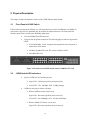


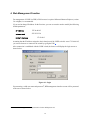


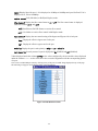
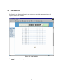
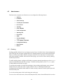
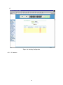
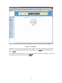
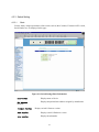
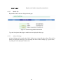

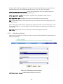
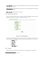
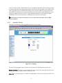

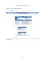

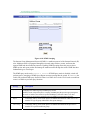
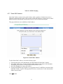


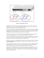

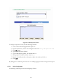
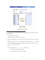
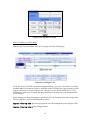

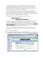
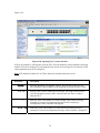
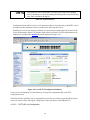

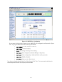
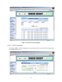
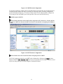
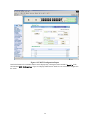
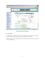


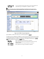
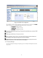
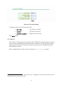
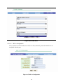
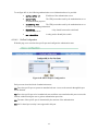
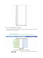
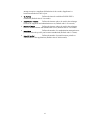


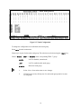

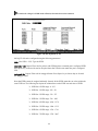
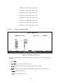


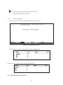
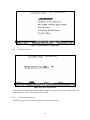
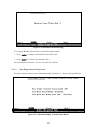
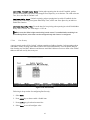
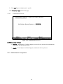


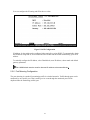
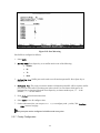
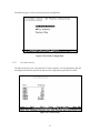


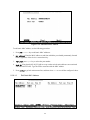

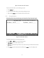
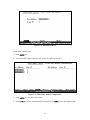
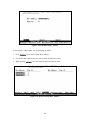
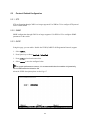
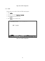

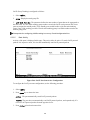


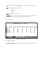
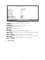
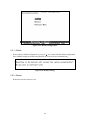

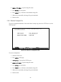
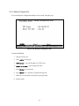

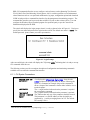


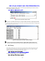
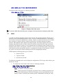

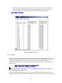


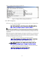
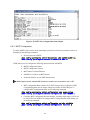
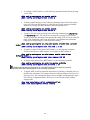
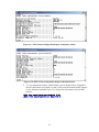
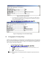
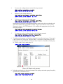
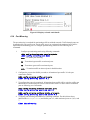

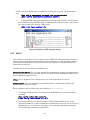

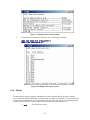
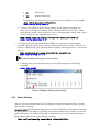


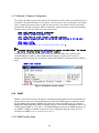

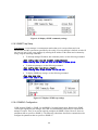
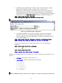


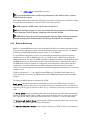


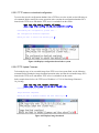
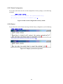


![LS5105 Document No 2 [PDF 1MB] - Australian Electoral Commission](http://vs1.manualzilla.com/store/data/005655823_1-2458abda02bbd8390d0ac9ba8bd86ac6-150x150.png)