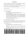
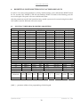
1
GsmAlarm-500 (V1.04)
GSM Alarm and Remote Control System
FEATURES
!
!
!
!
!
!
!
!
!
!
!
!
!
!
!
!
!
!
!
6 inputs.
Up to 15 protection zones.
3 programmable low current outputs + 1 high current relay output.
5 users are notified.
Possibility to connect up to 4 keypads.
20 programmable keypad access codes or iButton keys.
Automated remote control using up to 250 number Caller ID recognition without call cost.
Remote control using mobile phone keypad (through DTMF tones).
24 hour timer.
Two partial protection modes (STAY and SLEEP).
Possibility to divide the system into two independent partitions.
Possibility to send information to alarm monitoring station using the Contact ID protocol
through GSM voice call.
Possibility to connect up to 6 temperature sensors for temperature measurement.
Info-carrying SMS showing state of each sensor, power supply voltage, GSM signal
strength.
GSM JAMMING detection.
Programming and firmware upgrade via USB connection.
Remote programming over GPRS.
Integrated quad-band GSM module.
Wide operating temperature range: -35 … +65ºC.
_________________________________________________________________________________
GsmAlarm-500
Software ver. 1.04
T A B L E OF C ON T E N S
Table of Contents
1. General Information.........................................................................................................................1
1.1. Safety Instructions .......................................................................................................................1
1.2. Package Content ..........................................................................................................................2
1.3. Introdution....................................................................................................................................3
2. Connector and LED Functionality..................................................................................................4
2.1. Zone Input terminals Z1 to Z6.....................................................................................................4
2.2. Keypad Connection Terminals GR and YL ................................................................................4
2.3. Auxiliary Power Terminal AUX ................................................................................................5
2.4. Programmable Output Terminals C1, C2 and C3 .......................................................................5
2.5. BELL/SIREN Connection Terminals K1, K2 .............................................................................5
2.6. AC Power Terminals ...................................................................................................................5
2.7. BAT Connector............................................................................................................................5
2.8. External Microphone Connector .................................................................................................5
2.9. RESET Button .............................................................................................................................5
3. LED Indicators..................................................................................................................................6
3.1. NETWORK: GSM Module State and Signal Strength indicator................................................6
3.2. MODE: Alarm System Status Indicator ......................................................................................6
4. Installation .........................................................................................................................................7
4.1. General Installation Instructions..................................................................................................7
4.2. Wiring Diagrams..........................................................................................................................9
4.2.1. System with keypad access control ......................................................................................9
4.2.2. System with iButton access control......................................................................................9
4.2.3. Ways to connect alarm zones .............................................................................................10
4.3. Connection of Temperature Sensors..........................................................................................11
5. Programming...................................................................................................................................12
5.1. General Programming Instructions............................................................................................12
5.2. User and Alarm Monitoring Station numbers ..........................................................................12
5.2.1. Programming with Standard Mobile Phone .......................................................................12
5.2.2. Programming with SMS ....................................................................................................13
5.3. Programming System Parameters with SMS ......................................................................15
5.3.1. Programming Zones............................................................................................................15
5.3.1.1. Parameter “A”: Input Triggering Conditions ..............................................................16
5.3.1.2. Parameter “M”: System State after Input Triggering..................................................17
5.3.1.3. Parameter “P”: Partition Assignment and Partial Arm Methods: STAY, SLEEP .....17
5.3.2. Programming of Output C1-C4 (K1, K2) and Common System Parameters
“E”, “F”, “G”, “H”, “J”, “K”, “L”, “P”, “T” ..................................................................18
5.3.2.1. Output C1-C4 (K1, K2) Operating Mode ...................................................................19
5.3.2.2. Parameter “E”: the Way User Is Informed About Arming/Disarming .......................20
5.3.2.3. Parameter “F”: System Response to Incoming Calls and Number
of Calls in Alarm State ................................................................................................20
5.3.2.4. Parameter “G”: SMS Delay Time in Case of Power Supply Failure..........................20
5.3.2.5. Parameter “L”: SMS Structure and SMS Password Functionality .............................21
5.3.3. Programming Partition Names ...........................................................................................21
5.3.4. Setting System Clock..........................................................................................................21
5.3.5. Programming 24 Hour Timer .............................................................................................22
5.3.5.1. Timer Instructions........................................................................................................23
5.4. Programming Description of Input Zone State ........................................................................23
5.5. Programming User Names.........................................................................................................24
5.6. Programming SMS Password ....................................................................................................24
_________________________________________________________________________________
Software ver. 1.04
GsmAlarm-500
T A B L E OF C ON T E N S
5.7. Programming the System using the Keypad.........................................................................25
5.7.1. Programming Access Codes ...............................................................................................26
5.7.2. User Access Code Functionality ........................................................................................27
5.7.3. Exit Delay Time..................................................................................................................27
5.7.4. Parameter “T”: Entry Delay Time or Triggering Temperature..........................................28
5.7.5. Parameter “A”: Input Triggering Conditions ....................................................................28
5.7.6. Parameter “M”: System State after Input Triggering.........................................................28
5.7.7. Parameter “P”: Partitions Assignment and Partial Arm Methods......................................29
5.7.8. Parameter “I”: Pulse counting Mode..................................................................................29
5.7.9. Zone Response Time ..........................................................................................................29
5.7.10. Operating Time of Outputs C1-C4 and BELL .................................................................30
5.7.11. Operating Mode of Outputs C1-C4 and BELL ................................................................30
5.7.12. Parameter “E”: The Way User Is Informed About Arming/Disarming...........................31
5.7.13. Parameter “F”: System Response to Incoming Calls and Number
of Calls in Alarm State .....................................................................................................31
5.7.14. Parameter “G”: Delay Time of Report SMS about the Power Supply Failure ...............31
5.7.15. Parameter “H”: Data Transfer to the Alarm Monitoring Station .....................................31
5.7.16. Parameter “J”: System Response to Intentional GSM Jamming .....................................31
5.7.17. Parameter “L”: SMS structure and SMS Password Functionality...................................32
5.7.18. Parameter “P”: Partitioning ..............................................................................................32
5.7.19. Access Code Length (4 or 6 Digits) .................................................................................32
5.7.20. Exit Delay Audible Indication..........................................................................................32
5.7.21. Assigning Keypad Zones..................................................................................................32
5.7.22. Setting System Clock........................................................................................................33
5.7.23. Programming 24 Hour Timer ...........................................................................................33
5.7.24. Programming CONTACT ID User Account Number......................................................34
5.7.25. Temperature Correction....................................................................................................34
5.8. Programming iButton Keys ....................................................................................................34
5.9. Programming and Diagnostics Over the Internet ................................................................34
6. Resetting system settings to factory defaults................................................................................36
6.1. Manufacturer Programmed Parameters .....................................................................................36
7. Data Transfer to Alarm Monitoring Station................................................................................37
7.1. Programming Telephone Numbers of the Alarm Monitoring Station ......................................37
7.2. Programming CONTACT ID User Account Number...............................................................37
7.3. Modes Of Data Transfer To The Alarm Monitoring Station ....................................................38
7.4. CONTACT ID Protocol Codes..................................................................................................39
8. System Control Using the Keypad ................................................................................................40
8.1. Keypad Keys and LED Indicator Functionality ........................................................................40
8.1.1. [
] Key - Extended indication mode .............................................................................40
8.1.2. [TBL] Key - Trouble Display .............................................................................................40
8.1.3. [MEM] Key - Alarm Memory Display ..............................................................................40
8.1.4. [BYP] Key - Bypass Programming ....................................................................................41
8.1.5. [CLEAR] Key ....................................................................................................................41
8.1.6. [ENTER] Key .....................................................................................................................41
8.1.7. “~” Indicator ......................................................................................................................41
8.1.8. “StayD” (Status) Indicator..................................................................................................41
8.1.9. “OFF” Indicator ..................................................................................................................41
8.1.10. “ARM”, “SLEEP” and “STAY” Indicators .....................................................................41
8.2. Regular Arming ........................................................................................................................42
8.3. Stay & Sleep arming ..................................................................................................................42
_________________________________________________________________________________
Software ver. 1.04
GsmAlarm-500
T A B L E OF C ON T E N S
8.4. Disarming & Deactivating an Alarm ........................................................................................43
8.5. Panic Alarms ..............................................................................................................................43
8.6. Programmable output control ..................................................................................................43
9. System Control Using iButton Access Keys ...............................................................................43
10. Remote Arming & Disarming......................................................................................................44
11. System Operation in Alarm State ...............................................................................................45
12. Power Supply Monitoring ............................................................................................................45
13. GSM Jamming Detection .............................................................................................................46
14. System Control Using DTMF and SMS Commands.................................................................47
15. Warranty........................................................................................................................................49
16. Technical Characteristics.............................................................................................................50
_________________________________________________________________________________
Software ver. 1.04
GsmAlarm-500
GENERAL INFORMATION
1.
GENERAL INFORMATION
1.1. SAFETY INSTRUCTIONS
Please read and follow these safety guidelines in order to maintain safety of operators and people
around.
Retain all safety and operating instructions for future reference during the whole operating lifetime
of device.
The system must be powered by main 16-24V 50Hz ~1.5A AC or 18-24V 1.5A
DC power supply which must be approved by LST EN 60950-1 standard and
be easily accessible.
Any additional devices linked to the system GsmAlarm-500 (computer,
sensors, relays etc.) must be approved by LST EN 60950-1 standard.
External power supply must be reachable and can be connected to AC mains
only inside installation room with automatic 2-pole circuit breaker capable of
disconnecting circuit in the event of short circuit or over-current condition.
Open circuit breaker must have a gap between connections of more than
3mm.
System GsmAlarm-500 is a device mounted in limited access areas. Any
system repairs must be done only by qualified, safety aware personnel. There
are no parts you can change at place in the device.
The system must be used only with approved back-up battery to avoid fire or
explosion hazards. Special care must be taken connecting positive and
negative battery terminals.
The device is switched off by 2-pole circuit breaker and disconnecting back-up
battery connector.
Mains power and back-up battery must be disconnected before any
installation or tuning work starts. The system installation or maintenance
must not be done during stormy conditions.
_________________________________________________________________________________
GsmAlarm-500
Software ver. 1.04
1
GENERAL INFORMATION
Remote control and monitoring device GsmAlarm-500 has built-in radio transmitter operating on
GSM900 and GSM1800 networks.
Do not use the device where it can cause interferences and danger.
Do not arrange the device close to medical equipment and appliances.
Do not use the device in explosive environment.
Device is not resistant to moisture, chemical materials or mechanical damage.
This symbol on the product or on its packaging means that your electrical and electronic
equipment should be disposed at the end of life separately from your household wastes.
There are separate collection systems for recycling in EU. For more information, please
contact the local authority or the dealer where you purchased the product.
1.2. PACKAGE CONTENT
Main board GSMA-500 ..............................................................................Qnty 1
GSM antenna with magnetic fix and 2 m lead cable .................................Qnty 1
Microphone ................................................................................................Qnty 1
Microphone connector ...............................................................................Qnty 1
Load resistors 2,2k ±5% ............................................................................Qnty 6
Load resistors 4,7k ±5% ............................................................................Qnty 7
Battery connection wire ..............................................................................Qnty 1
Fastening clips ............................................................................................Qnty 4
User‘s manual ............................................................................................Qnty 1
_________________________________________________________________________________
GsmAlarm-500
Software ver. 1.04
2
GENERAL INFORMATION
1.3. INTRODUTION
GsmAlarm-500 can be used for protection of houses, apartments, cottages and other buildings. In the
case of trespass of the protected zone GsmAlarm-500, depending on the programmed system
operating algorithm, can switch the siren on, call and send SMS messages to five users and transfer
information to the alarm monitoring station by Contact ID protocol through GSM voice call.
User answers the call, can listen, what is going on in the unit and control the system using his mobile
phone keypad (through DTMF tones).
GsmAlarm-500 has 3 (4, if siren is not used) programmable outputs, intended for remote control of
different devices. User can turn on/off heating, ventilation or lighting systems etc, by using his
mobile phone just by typing a 2-digit code or sending SMS to the control device.
Device works perfect for remote control of automated gates, fences and electromagnetic door locks.
In order to open the gate, user calls GsmAlarm-500 number. Then GsmAlarm-500 checks the caller’s
number in the list of programmed user numbers and in the case of positive find, switches on the gate
control device and cancels the call automatically. 250 users are able to control the gate.
Up to 4 keypads can be connected to GsmAlarm-500. By using the keypad users can arm or disarm
the system and configure system parameters. Following keypad LED indicators you can determine
protected unit state, system mode etc.
The system is controlled by iButton (also known as DALLAS) keys. Several control functions can be
assigned to each key. Example: a user can activate a protection mode and a controllable output by
touching the contact with the key. A user name can be assigned to each key (as well as to a keypad
code) that will be indicated in SMS messages. Up to 20 iButton keys can be programmed.
If keypad or iButton keys are not used, the system may be armed and disarmed by a simple switch or
a short free call. The installation is controlled exclusively from the user telephone. If the system
receives a call, coming not from the user's phone, the call is immediately interrupted and the user is
sent an SMS message, specifying the caller's phone number. The user is also informed by an SMS
message about loss and restoration of AC mains power supply.
The system answers only to the numbers programmed. If the system receives a call, coming not from
the user's phone, the call is immediately interrupted and the user is sent SMS, specifying the caller's
phone number. SMS messages are also sent to users in case of power loss and restoration.
The system has temperature measurement possibility. Up to 6 temperature sensors can be connected
to GsmAlarm-500 device. If temperature exceeds or subsides programmed range, system sends SMS
to user(s), relevant programmable output can be activated/ deactivated.
24 hour timer enables activation/deactivation of programmable output, arming or disarming,
receiving SMS messages with protected object state information on a desired time.
The system has capability to detect intentional jamming of GSM. The siren is activated upon
detection of the jamming signal, and the user is informed thereof by an SMS message about it after
clearing of GSM jamming signal. The message indicates the jamming onset time.
GsmAlarm-500 parameters may be set via a computer using the GSM alarm configuration tool
GAPROG. The module is accessible via an USB port or over the internet through GPRS channel. If a
computer is unavailable, the system is set up by a keypad or SMS messages.
_________________________________________________________________________________
GsmAlarm-500
Software ver. 1.04
3
TERMINAL CONNECTIONS
2.
CONNECTOR AND LED FUNCTIONALITY
SIM CARD
GSM ANTENNA
CONNECTOR
(SMA)
RESERVE
BATTERY
CONNECTOR
SYSTEM STATUS
LED INDICATORS
NETW.
-
MODE
USB
+
SIM CARD
SLOT
BATT
RESET
GSM MODULE
M+ MMICROPHONE
CONNECTOR
(C4)
GND Z1 Z2
Z3
Z4
Z5
Z6 GND GR YL AUX C1 C2 C3
K1 K2
AC
Connection terminals and LED indicators
2.1.
ZONE INPUT TERMINALS Z1 to Z6
Inputs Z1-Z6 are used to connect alarm detectors or temperature
sensors KTY81-110 (PHILIPS).
+5V
2.2k
Processor
GND
Z
The zones are designed to work with End of Line (EOL) resistors
of 2.2 k! (and 4.7 k! in ATZ mode, see Ch. 4.2.3). The system
becomes triggered both when the input circuit is broken as well as
when it is short-circuited.
The inputs can operate in a non EOL mode (see Ch. 4.2.3). In this
case EOL resistor in not required. The system is triggered after
breaking or short-circuiting of the input circuit (depending on the
programmed "active" level).
Equivalent diagram of zone input
2.2.
KEYPAD CONNECTION TERMINALS “GR” and “YL”
Use GR, YL, GND and AUX terminals to connect PARADOX K636, K10V/H (MG10LEDV/H),
K32 (MG32LED) or K32LCD (MG32LCD) keypad. These terminals can also be used for connection
of the iButton key reader.
_________________________________________________________________________________
Software ver. 1.04
GsmAlarm-500
4
TERMINAL CONNECTIONS
2.3.
AUXILIARY POWER TERMINAL “AUX”
The auxiliary power supply can be used to power motion detectors and other devices requiring 12
VDC. “AUX” is short-circuit-protected. Max load current is 1 A.
2.4.
PROGRAMMABLE OUTPUT TERMINALS “C1”, “C2” and “C3”
33
C
The programmable output is a 150 mA maximum switch to ground. A 33 ohm
current limiting resistor is connected in series. A small relay, a buzzer or other
DC operated device may be connected between the 12 VDC “AUX” (positive)
terminal and the “C” (switched negative) terminal on the main board.
Relays with 12V operating voltage and current not exceeding 150 mA max, are
recommended for device control.
GND
Output operating modes are described in Ch. 5.3.2.1
Equivalent diagram of C output
2.5.
BELL/SIREN CONNECTION TERMINALS “K1” and “K2”
These terminals are relay contacts of the programmable output C4. K1 and K2 are used to connect
audio siren or extra-commutated device.
Commutated current may reach 5 A max.
2.6.
“AC” POWER TERMINALS
Use a 16-18 VAC transformer with a minimum 40 VA rating to supply AC power to the GsmAlarm500.
2.7.
“BATT” CONNECTOR
Use this connector to connect the backup battery. Max capacity of the backup battery is 1,2 Ah.
Voltage: 12 VDC.
2.8.
EXTERNAL MICROPHONE CONNECTOR
This connector is used to connect an external microphone. Connect white wire to contact M+, black –
to M-. In order to avoid interference install microphone as far as possible from GSM antenna.
2.9.
RESET BUTTON
RESET button is used to restore factory default settings (see. Ch. 6).
_________________________________________________________________________________
Software ver. 1.04
GsmAlarm-500
5
LED INDICATORS
3.
LED INDICATORS
3.1. NETWORK: GSM MODULE STATE AND SIGNAL STRENGTH INDICATOR
Indicator state
Out.
Continuously On.
Blinking more frequently than once a
second.
Blinks 5 times, short break after.
Blinks 4 times, short break after.
Blinks 3 times, short break after.
Blinks 2 times, short break after.
Blinks once, short break after.
Explanation
GSM module is not in use. No power supply or
system failure.
There is no GSM operator network registration.
Possible causes: SIM card PIN code request is not
deactivated, antenna not connected or poor network
connection quality.
GSM module is in use: outgoing call or SMS is
being sent.
Very good signal.
Good signal.
Satisfactory connection.
Weak connection.
Poor connection.
3.2. MODE: ALARM SYSTEM STATUS INDICATOR
Indicator state
Out.
Continuously On.
On with short breaks.
Blinking with low frequency (once in
2-3 sec.).
Blinking more frequently than once a
second.
Blinking very rapidly for 2-3 sec.
Explanation
No power supply or system failure.
System is operative, disarmed, no zone sensors have
been triggered.
System is operative, disarmed, but one or more zone
sensors have been triggered.
System is armed.
System is in alarm state.
SMS instruction or DTMF command receipt
confirmation.
_________________________________________________________________________________
GsmAlarm-500
Software ver. 1.04
6
INSTALLATION
4.
4.1.
INSTALLATION
GENERAL INSTALLATION INSTRUCTIONS
According to manufacturer recommendations, hire qualified security system specialist (or company)
to perform system installation works. Self-dependent installation of the system can be performed
only if person possess basic knowledge in electricity and electronics, otherwise device might be
irrecoverably damaged.
System should be assembled in metal housing 7TRP20 as recommended.
GSM antenna
Antenna cable
Metal housing (7/TRP20)
GSM
antenna
connector
NETW.
> 6 cm.
MODE
+
-
USB
+
+
SIM CARD
RESET
GSM MODULE
M+
M-
MICROPHONE
CONNECTOR
GSMA-500
Board
fixture holes
4 x 3.5 mm
GND
Z1
Z2
Z3
Z4
Z6 GND GR
Z5
YL AUX
(C4)
C1
C2
C3
K1
K2
AC
HOLE FOR CABLES
-
+
BLUE
RED
+
Housing
fixture holes
4x5mm
-
BACKUP
BATTERY
AC 230V
AC 18V
POWER SUPPLY
TRANSFORMER
(TRP 20/01)
SAUGIKLIS
AC 12V 1.3Ah
(CT1.3-12)
T 0.16A
LSTEN 60950
Recommended layout of system elements in 7/TRP20 type housing
Use double isolated cable 3x0,75 mm2 for 230V power supply. Circuit breaker or other surge
protection device should be installed in the 230V power line.
_________________________________________________________________________________
GsmAlarm-500
Software ver. 1.04
7
INSTALLATION
Antenna is fixed on the top of outer side of metal housing.
It is recommended to use standard motion (SRP-300) and fire (EA318-4) sensors in alarm system.
Use standard 6-8 wired single core cable designed for installation of alarm systems. Siren DC12V
500mA (S-108) is recommended for sound alarm, use double isolated cable 2x0,75 mm2 to connect it
to the system. Backup battery must be PB-acid (CT1.2-12).
It is recommended to install remote control relays into sockets which can be easily fixed to metal
housing. Operating current of relay coil can not exceed 150mA max. Relays are selected depending
on desirable commutative voltage and current.
Connection according to the wiring diagram presented in Chapter 4.2.1 is recommended, if the
system is controlled by a keypad. Up to 4 Paradox K636, K10V/H (MG10LEDV/H), K32
(MG32LED) or K32LCD (MG32LCD) keypads can be connected to GsmAlarm-500. Each of the
said keypads has a single keypad zone (the blue wire). Use of keypad zones is recommended for
connection of magnetic door sensors. Activation of a keypad zone is described in Chapter 5.7.21.
Connection according to the wiring diagram presented in Chapter 4.2.2 is recommended, if the
system is controlled by iButton (DALLAS) keys DS1990A or a simple switch. Short beeps are
generated by an ancillary buzzer while exiting a room and a continuous sound, after entering the
room. Any buzzer with power supply of 12 V DC and maximum operating current of 100 mA may
be used (e.g., BPT-23CXW-1). The system status LED indicator woks in sync with the “MODE”
indicator (see Ch. 3.2). The state of this indicator allows identification of the alarm system status and
verification of closure of all protected zones before arming the alarm system. The status indicator
should be mounted indoors in a well visible location. The reader DS9092LED of iButton keys is
equipped with an embedded LED indicator that can be used as system status indicator.
If the system is controlled by an ON/OFF switch, the system is armed by opening the switch contacts
and disarmed by closing the contacts.
Input circuits are connected according to corresponding diagram provided in Chapter 4.2. It is
recommended to turn off zones that aren‘t used – to change value of A parameter to “A00” (see Ch.
5.3.1.1).
A SIM card needed for GsmAlarm-500 operating, you may acquire it from any GSM service
provider. Before inserting SIM card into GsmAlarm-500 SIM card slot set PIN code request off. It
can be performed simply inserting SIM card into any standard mobile phone and following certain
phone user manual instructions.
After finishing installation, insert SIM card into GsmAlarm-500 SIM card slot, turn system power on,
then wait until LED “NETWORK” will start to flash and LED “MODE” will be constantly alight. In
case “NETWORK” is constantly alight, check if SIM card‘s PIN code request is off and GSM
antenna is connected. GSM signal quality can be evaluated according the blinking frequency of
“NETWORK” indicator. Connection is very good if it blinks 5 times with short break after.
“NETWORK” indicator blinking fewer times, indicates weaker connection. System works in steady
state if indicator blinks 3-5 times. Position of GSM antenna might be changed in order to improve
signal quality.
Perform system programming when the system is disarmed. Protected zones must be closed
(indicator “MODE” constantly alight). Detailed programming description can be read in Chapter 5.
_________________________________________________________________________________
GsmAlarm-500
Software ver. 1.04
8
INSTALLATION
4.2.
WIRING DIAGRAMS
4.2.1. SYSTEM WITH KEYPAD ACCESS CONTROL
GND Z1 Z2
Z3
Keypad No.1
Z4
Z5 Z6 GND GR YL AUX C1 C2 C3 K1 K2
Power supply
transformer
RED
YELLOW
GREEN
BLACK
Keypad. zone 1
+
AC 16-24V
~1.2 A
2-wire smoke detector
E318-2LED
1k
-
RED
YELLOW
GREEN
BLACK
Keypad zone 2
AC 230V
-
Siren
BLUE
Keypad No.2
AC
4.7k
+
+Power supply for
BLUE
1k
-
Additional relays for
extra-commutated devices
motion or fire
detectors
4.2.2. SYSTEM WITH iBUTTON ACCESS CONTROL
GND Z1 Z2
Z3
Z4
Z5 Z6 GND GR YL AUX C1 C2 C3
K1 K2
AC
Power supply
transformer
GRN.
+
System status
indicator
YEL.
DS9092LED
Siren
iButton key
reader
WH.
AC 16-24V
~1.2 A
AC 230V
-
2-wire smoke detector
E318-2LED
-
I-Button
-
GREY
+
4.7k
+
Buzzer
BPT-23CXW-1
Switch ON/OFF
(if iButton key is not used)
Additional
relay
+
-
Power supply
for motion or
fire detectors
_________________________________________________________________________________
GsmAlarm-500
Software ver. 1.04
9
INSTALLATION
4.2.3. WAYS TO CONNECT ALARM ZONES
GND
Z GND
NO
GND
Z
Z
GND
NC
NC
2.2K
A1Y
Z
A3Y
A2Y
2.2K
NO
with one EOL resistor
(A3Y)
no EOL
GND
Z
Z07...Z15
4.7K
NC
NC
2.2K
Z01 ... Z06
with two EOL resistors
ATZ mode (A4Y)
NC: normally closed contacts. NO: normally open contacts.
A1Y-A4Y: zone operating modes, parameter “A” (see Chapter 5.3.1.1).
GsmAlarm-500 has 6 inputs Z1...Z6, corresponding to the zone numbers Z01...Z06. If 6 zones are
sufficient for protection of the object, the inputs may operate in non EOL or EOL modes. A load
resistor 2.2k is used in EOL mode. In this case, the system activates both at short-cutting the circuit
and at breaking the circuit. The resistor is mounted in the housing of an alarm sensor.
If 6 zones are insufficient, an advanced technology zone (ATZ) mode may be used. In this case, one
input can control two zones. Two parallel connected resistors are used in ATZ mode. Load resistors
of 2.2k are associated with the zones Z01…Z06. Load resistors of 4.7k are associated with the zones
Z07…Z15. The number of the main ATZ zones (Z01…Z06) should correspond to the number of the
extended ATZ zones (Z07…Z15).
The main and the extended zones are associated automatically in the order of increasing zone
number. Example: If ATZ mode has the main zones Z01, Z02, Z04 and the extended zones Z08,
Z09, Z10, the zone Z01 will be associated with zone Z08, zone Z02, with zone Z09, and zone Z04,
with zone Z10.
If a 2-wire fire sensor is connected to the programmable output C3, the zone Z07 should be set as an
additional fire zone (A5Y mode, see Ch. 5.3.1.1), and the output C3 should work in the following
mode: M01T05 inverted (see Ch. 5.3.2 and Ch. 5.7.11). A load resistor of 4.7k also should be used.
A triggered fire sensor is switched off with an SMS message or a DTMF/keypad command for C3
output (see Ch. 14).
_________________________________________________________________________________
GsmAlarm-500
Software ver. 1.04
10
INSTALLATION
4.3.
CONNECTION OF TEMPERATURE SENSORS
GsmAlarm-500 has temperature measurement possibility. Up to 6 temperature sensors KTY81-110
(PHILIPS) can be connected to the GsmAlarm-500.
2 pin terminal block
GsmAlarm-220
Input
GND
Z
Fixing hole
T emperature sensor
KTY81-110
PHILIPS
Shield
In order to minimise influence of external interferences and measurement error, it is recommended to
use shielded twisted pair cable 0.5 mm². Shield is connected to ground wire only in one end, close to
GsmAlarm-500 board. Use 2 pins terminal block with a fixing hole for temperature sensor fastening.
Parameter “A” must be changed in order to activate temperature measurement mode. (see Ch.
5.3.1.1). Input parameter T defines alarm temperature. Alarm temperature can be programmed in
0...+99 ºC rage (T00 - T99).
In temperature measurement mode input operates the same as in protection mode, i.e. all operating
modes are valid with two exceptions:
a) No entry delay in A40 A50, system generates alarm instantly, after temperature reaches
programmed value;
b) No prohibition for arming, i.e. user can activate armed mode although temperature
measurement zone has been triggered.
Recommended values of parameter M: M40 or M00. In first case, if the system is in armed mode and
temperature reaches programmed value, user receives SMS message (siren will not turn on and
system will not dial).
If two triggering temperatures are required, an extended zone (Z7…Z15) may be assigned to the
main temperature zone (Z1…Z6). The A8Y mode or A9Y mode should be activated for the ancillary
temperature zone (see Ch. 5.3.1.1). The extended temperature zone operates according to the
temperature measured by the main temperature zone. The number of the main temperature zones
should correspond to the number of the extended temperature zones.
_________________________________________________________________________________
GsmAlarm-500
Software ver. 1.04
11
PROGRAMMING
5.
5.1.
PROGRAMMING
GENERAL PROGRAMMING INSTRUCTIONS
It is recommended to perform the system setup and tuning by a computer via USB port, using the
GSM alarm configuration tool GAPROG. The GsmAlarm-500 main board is connected to the
computer with a standard USB A-B cable. The configuration tool is downloadable from the website
of the manufacturer: www.eltech.lt.
The GSM alarm configuration tool GAPROG allows setting up of the system over the internet (see
Ch. 5.9).
If a computer is unavailable, the system is set up by a keypad or SMS messages.
GsmAlarm-500 parameters can be divided into two groups. First group – user phone numbers which
are stored in SIM card memory. User phone numbers can be programmed by using standard mobile
phone of any type (see Ch. 5.2.1) or remotely, sending SMS message with the phone numbers of
users to GsmAlarm-500 (see Ch. 5.2.2).
Second group – parameters, defining system operating algorithms, names of protected zones and
programmable outputs. These parameters are stored in the memory block of GsmAlarm-500 device.
The parameters of the system can be programmed by sending SMS message (see Ch 5.3) or by using
Paradox keypad (see Ch. 5.7).
It is recommended to change the SMS password at the end of programming (see Ch. 5.6).
5.2.
USER AND ALARM MONITORING STATION NUMBERS
If GsmAlarm-500 is used for protection, five user numbers can be programmed: ALRNR1, ALRNR2,
ALRNR3, ALRNR4 and ALRNR5, and two alarm monitoring station numbers can also be
programmed: CIDNR1, CIDNR2. Users can arm/ disarm the system, calls will be directed and SMS
messages will be sent to these users. If only one user exists, he must be programmed under ALRNR1.
GsmAlarm-500 will send SMS messages to this specific user in case of main power supply loss or if
an unknown number calls the system. If armed mode is turned on or off with the single touch of the
keypad or by turning the switch ON/OFF (if the keypad is not used) control dials and SMS messages
are also directed to the first user. Other four user numbers are not obligatory.
In case GsmAlarm-500 is used only for gate control it is not necessary to programme ALRNR1ALRNR5. Up to 250 user numbers, with the possibility to control the outputs C1, C2, C3, C4 and
BELL with a short call, can be programmed in this case. Any name can be ascribed to user. Output
operating mode has to be M04 or M05 (see Chapter 5.3.2.1).
5.2.1. PROGRAMMING WITH STANDARD MOBILE PHONE
Insert SIM card into a standard mobile phone. Enter user name into SIM card number book using
capital letters e.g. ALRNR1 and corresponding phone number. We recommend enter the number with
international code. (E.g. +370...).
_________________________________________________________________________________
Software ver. 1.04
GsmAlarm-500
12
PROGRAMMING
If GsmAlarm-500 is used for gate control, number of extra user numbers can be as large as fits into
the SIM card (up to 250). Any name can be ascribed to user.
When programming alarm monitoring station number you must use capital letters and enter name:
CIDNR1 (CIDNR2) and number (numbers) of alarm monitoring station.
Important!
It‘s important to note that while programming SIM card memory should be active (not phone
memory). Otherwise the user number will be recorded in the mobile phone memory used for
programming and the SIM card will remain empty.
After having programmed all user numbers, it is recommended to check whether SMS service center
number is programmed. Simplest way to check: send any SMS from the phone used for
programming. If it is sent successfully we can be sure that SMS centre number has been programmed
correctly. Otherwise, programme SMS center number following the mobile phone’s user manual.
SMS center number can be learnt from GSM service provider.
After completion of programming and checking whether SIM card PIN code request is switched off,
take the SIM card off from the mobile phone and insert it into GsmAlarm-500 SIM card slot.
5.2.2. PROGRAMMING WITH SMS
In order to program the main user numbers, send the following SMS from any mobile phone into
GsmAlarm-500:
AAAAAAAA ALRNR1:+3706123456789 ALRNR2:+3706123456789 ALRNR3:+3706123456789
ALRNR4:+37061234546789 ALRNR5:+3706123456789 CIDNR1:+3706123456789 CIDNR2:+3706123456789
AAAAAAAA: eight digit alphanumeric SMS password, which is obligatory in the beginning of
each SMS. Manufacturer-programmed password is AAAAAAAA. User can change the password on
his own desire (see Ch.5.5).
ALRNR1 ... ALRNR5: user numbers.
CIDNR1, CIDNR2: alarm monitoring station numbers.
Important:
a) No characters/spaces can be used before the password;
b) No spaces are allowed before and after the colon;
c) Spaces must follow the password and each phone number;
d) It is recommended to enter user numbers with international code (e.g. +123…).
It is not necessarily to send all user numbers. e.g., in order to programme only the first user number,
send the following SMS:
AAAAAAAA ALRNR1:+3706123456789
Receipt and decrypting of the SMS by GsmAlarm-500 is confirmed by blink of indicator MODE.
The phone, which has sent the programming SMS, immediately receives a confirming SMS with
programmed numbers.
_________________________________________________________________________________
Software ver. 1.04
GsmAlarm-500
13
PROGRAMMING
In order to delete unnecessary number, send the following SMS:
AAAAAAAA ALRNR2:N
Number ALRNR2 is deleted, user receives SMS with programmed numbers. In order to replace one
number with another, no separate instruction for deletion needs to be sent.
In order to receive SMS with programmed numbers ALRNR1 ... ALRNR5, send GsmAlarm-500
the following SMS:
AAAAAAAA NRINFO
Extra user numbers (only for gate control) are programmed by sending the following SMS:
AAAAAAAA ADDNR:+3701234567891 ADDNR:+3701234567892 ADDNR:+3701234567893
ADDNR: – new number programming instruction.
+3701234567891 – new user number.
If the numbers programmed successfully, the user, who sent the message, receives SMS with newly
programmed number. In this case the confirmation message will be:
USER1:+3701234567891 USER2:+3701234567892 USER3:+3701234567893
USER1 – name, assigned to the new number.
If a short call controls several outputs, an additional number may be assigned only to a single output.
In this case, the programming message is the following:
AAAAAAAA ADDNR-C1:+3701234567891 ADDNR-C2:+3701234567892
ADDNR-C3:+3701234567893 ADDNR-C4:+3701234567893
The first number controls only the output C1, the second, C2, the third, C3, the fourth, C4 (K1, K2).
Up to 8 user numbers might be programmed with one SMS message.
In order to delete the extra user number, send to GsmAlarm-500 the following message:
AAAAAAAA DELNR:+3701234567891 DELNR:+3701234567892 DELNR:+3701234567893
Specified numbers will be deleted and user receives the confirming SMS:
DELETED:+3701234567891 DELETED:+3701234567892 DELETED:+3701234567893
Up to 8 user numbers might be deleted with one SMS message.
_________________________________________________________________________________
Software ver. 1.04
GsmAlarm-500
14
PROGRAMMING
In order to receive SMS message indicating all programmed numbers, following message must be
sent to GsmAlarm-500:
AAAAAAAA NRLIST
User receives one or more SMS messages with all programmed numbers listed.
Note! Up to 8 user numbers can be sent in one SMS message. If 250 numbers are programmed
GsmAlarm-500 will send 32 SMS messages!
5.3.
PROGRAMMING SYSTEM PARAMETERS WITH SMS
All GsmAlarm-500 input and output operating modes, delay times and names can be programmed
with the help of SMS. First, it is recommended to receive SMS with programmed parameters and
then to send the same SMS with corrected parameters back to GsmAlarm-500.
5.3.1. PROGRAMMING ZONES
In order to receive SMS with zone Z1 - Z15 parameters, send GsmAlarm-500 the following SMS:
AAAAAAAA ZPARAM
SMS can be sent from any GSM phone, not necessarily the user’s. GsmAlarm-500 confirms
receiving the message with frequent blinking of MODE indicator and sends four SMS messages
including input parameters Z1- Z15. First message contains Z1 – Z4 parameters, second – Z5 – Z8,
third – Z9 – Z12 and Z13 - Z15 parameters in fourth SMS message. Received message with input Z1
– Z4 parameters will look as follows:
AAAAAAAA Z01:A30M70P10I06T20 Zone1, Z02:A30M70P10I06T00 Zone2,
Z03:A30M70P10I06T00 Zone3, Z04:A30M70P10I06T00 Zone4,
AAAAAAAA: - password.
Z
- zone input number.
A30 - parameter defines operating mode of the corresponding input (see Ch. 5.3.1.1).
M70 - parameter defines system response to the violation of protected zone and which users are
informed if certain zone sensors are triggered (see Ch. 5.3.1.2).
P10 - partial protection mode (see Ch. 5.3.1.3).
I06 - the pulse counting mode. When the first number is larger than 1, the zone operates in the
pulse counting mode. After the zone triggers N number of times during the preset duration, the
system switches over to the alarm state. N: the first digit. The second number establishes the duration
of pulse counting. Multiplication of this number by 10 produces the time in seconds. Minimal time:
10 seconds (1), maximal time: 90 seconds (9). The factory preset time: 60 seconds. If N=0 or N=1,
the pulse counting mode is switched off.
_________________________________________________________________________________
Software ver. 1.04
GsmAlarm-500
15
PROGRAMMING
T20 - entry delay. If the system is armed and relevant input is triggered, the system switches siren
on and sends SMS only after expiration of the given delay time. Possible values: 0...99 seconds.
If zone is in temperature measurement mode, value of T parameter corresponds to triggering
temperature (see Ch. 5.3.1.1).
Possible values: 0...99 ºC.
Zone1, Zone2, Zone3, Zone4 – zone names, which are seen in the SMS after alarm triggering. User
can change the name of zone under his own discretion. Maximum number of name characters: 16.
5.3.1.1.
PARAMETER “A”: INPUT ZONE TRIGGERING CONDITIONS Addr: [201-216]
Input zone triggering conditions
Input zone operating mode
AXY
X
0
Y
0
Alarm is activated if contacts are
closed (NO, see Ch. 4.2).
1
1
Delay zone 2)
24H zone. 3)
Alarm is activated if contacts are
opened (NC, see Ch. 4.2).
2
2
Fire zone 4)
EOL mode, load resistor is required
(see Ch. 4.2).
ATZ (advanced technology zone).
2,2 k! and 4,7 k! load resistors are
required (see Ch. 4.2).
2-wire smoke detector connected to
the PGM output C3 1).
3
3
ON/OFF zone. 5)
4
4
5
5
-
-
6
Temperature measurement mode.
Alarm is activated if measured
temperature overcomes programmed
temperature T.
Temperature measurement mode.
Alarm is activated if measured
temperature is lower than
programmed temperature T.
-
7
8
8
9
-
Input disabled.
Follow zone. 6)
Dual activation delay zone. 7)
Dual activation 24-hour zone. 7)
Force arm, Delay zone.
Force arm, Follow zone. Force
arming allows to arm the system
without waiting for all zones to
close.
-
1) Only zone Z7 can operate in this mode. PGM output C3 must operate in mode: M01T05 inverted.
2) Delay zone. After relevant zone is being triggered, the system will generate alarm only in armed
mode, after expiration of the programmed entry delay time.
3) 24-hour zone. After relevant zone is being triggered, the system generates alarm in armed or
disarmed mode, siren operates constantly and delay time is ignored.
4) Fire zone. The system generates alarm in armed or disarmed mode. Siren operates with
interruptions.
5) ON/OFF zone. Mode designated to arm or disarm the system if keypad is not used.
_________________________________________________________________________________
Software ver. 1.04
GsmAlarm-500
16
PROGRAMMING
6) Follow zone. After violation of this zone alarm goes on immediately, if other zone with delay isn‘t
violated. If firstly zone with delay is violated (for example, doors are opened), “follow” zone receives
delay time of earlier violated zone. It is recommended to apply this mode to motion sensor zone, if
sensor is installed before the entry doors to the room.
7) System is responding both to zone activation and restoring in dual activation mode. After
activation of the zone, system is responding in the same way as in mode “0” and “1”. After zone
recovery (when zone comes back to the initial state), system doesn’t call and doesn’t turn on the
siren. Users receive only SMS message (if SMS message sending is activated; see Chapter 5.3.1.2).
5.3.1.2.
PARAMETER “M”: SYSTEM STATE AFTER INPUT TRIGGERING
Addr: [241-256]
Type of alarm after input triggering
Users,
getting
information
about
MXY
zone violation
X
Y
All functions, described below, are
0
0
All (ALRNR1-ALRNR5).
deactivated.
Only siren is operating.
1
1
Only user ALRNR1.
System is calling.
2
2
Only user ALRNR2.
Siren and calling.
3
3
Only user ALRNR3.
System is sending SMS message.
4
4
Only user ALRNR4.
Siren and SMS.
5
5
Only user ALRNR5.
Calling and SMS.
6
6
Users ALRNR1 and ALRNR2.
Siren, calling and SMS.
7
7
Users ALRNR1, ALRNR2 and
ALRNR3.
8
Users ALRNR1, ALRNR2,
ALRNR3 and ALRNR4.
9
All (ALRNR1-ALRNR5), but not
the alarm monitoring station.
Important: alarm monitoring station is informed when data transfer to monitoring station is turned
on (see Ch. 7.3), number X is higher than 0 and number Y isn’t equal to 9.
5.3.1.3.
PARAMETER “P” PARTITION ASSIGNMENT AND PARTIAL ARM
METHODS: STAY, SLEEP
Addr: [281-296]
Partition assignment
PXY
-
X
-
Y
0
Zone assigned to the first partition.
Zone assigned to the second partition.
Zone assigned to both partitions.
1
2
3
1
2
3
Partial arming mode STAY and
SLEEP.
In SLEEP and STAY modes zone
not active.
Zone is active in STAY mode.
Zone is active in SLEEP mode.
Zone is active in SLEEP and STAY
modes.
Manufacturer-programmed value: P10.
_________________________________________________________________________________
Software ver. 1.04
GsmAlarm-500
17
PROGRAMMING
5.3.2. PROGRAMMING OUTPUTS C1-C4 (K1, K2) AND COMMON SYSTEM
PARAMETERS “E”, “F”, “G”, “H”, “J”, “K”, “L”, “P”, “T”
In order to receive SMS with output and common system parameters, send GsmAlarm-500 the
following SMS:
AAAAAAAA CPARAM
Receiving the message is confirmed by blinking of indicator “MODE”, SMS with current system
parameters is being sent:
AAAAAAAA C1:M01T00 OutC1, C2:M05T05 OutC2, C3:M01T05 OutC3, C4:M06T02 Siren,
S01:E20F31G01H00J00K00L32P00T20
C1 - number of programmable output. C4 corresponds to siren connection terminals K1, K2.
M01 - output operating mode (see Ch. 5.3.2.1).
T00 - output operating time. Outputs C1-C3: in seconds, C4 (K1, K2): in minutes.
OutC1, OutC2, OutC3 and Siren - programmable output names. User can change the name under
his own discretion. Maximum number of name characters: 16.
S01: - command for common system parameters programming.
E20 - the way to inform user about arming/disarming. User can be informed by short call or SMS
message. (see Ch. 5.3.2.2) .
F31 - system response to incoming/outgoing calls and number of calls in alarm state. (see Ch.
5.3.2.3).
G01 - SMS delay time in case of the main power supply failure (see Ch. 5.3.2.4).
H00 - modes of data transfer to the alarm monitoring station. (see Ch. 7.3).
J01 - the system response to intentional GSM jamming. Possible values: J00, J01, J02, J03.
J00: detection of jamming signal deactivated.
J01: an SMS message is sent to users after resuming of communication. The message
indicates the GSM jamming onset time.
J02: detection of GSM jamming signal activates the siren.
J03: operates as the functions J01 and J02.
K00 - the method of system control.
K00: the system is controlled by a PARADOX keypad.
K01: the system is controlled by a iButton (DALLAS) keys.
K02: the system is controlled by an ON/OFF switch.
L32 - SMS structure and SMS password functionality.
P00 - partitioning. P00: partitions do not exist. P01: system is divided into two partitions.
T20 - entry delay time. Possible values: 00 – 99 seconds.
After correction of the parameters SMS message is sent back to GsmAlarm-500.
_________________________________________________________________________________
Software ver. 1.04
GsmAlarm-500
18
PROGRAMMING
5.3.2.1.
Output
mode
M00
M01
M02
M03
M04
M05
M06
M07
M08
M09
M10
M30
M11
M12
M13
M14
M15
M16
M17
M18
M19
M20
M21
M22
M23
M24
M25
OUTPUT C1-C4 (K1, K2) OPERATING MODE
Addr:[321-325]
Explanation of operating
Output controlled by DTMF or SMS instructions.
If zero operating time is programmed (T00), output is activated/deactivated and
remains in the same state after receiving DTMF or SMS instruction.
If not zero operating time is programmed, after receiving DTMF or SMS
instruction, output is activated, it deactivates automatically after expiration of the
programmed time.
System state indicator mode. Output is in operating together with MODE indicator.
Output is activated, when system is armed. Open contact, when system is disarmed.
Control by short call without number recognition function. Output is activated with
a call from any number. If zero operating time is programmed (T00), output state
changes after a call and remains unchanged till the next short call.
If not zero operating time is programmed, after receiving short call instruction
output is activated, it deactivates automatically after expiration of the programmed
period.
Control by short call with number recognition function (gate control mode). This
mode operates analogue to M04, thus it is activated only if short call number
coincides with programmed numbers.
Siren mode.
Siren mode with audible confirmation. After arming, one short audible beep is
heard. After disarming, two short audible beeps are heard.
Output is activated in case of wiring trouble of fire sensor.
Output is activated in case of AC mains failure.
Output is activated in case of GSM signal loss.
Additional audible buzzer mode.
Output state depends on the state of zone Z1 *
Output state depends on the state of zone Z2 *
Output state depends on the state of zone Z3 *
Output state depends on the state of zone Z4 *
Output state depends on the state of zone Z5 *
Output state depends on the state of zone Z6 *
Output state depends on the state of zone Z7 *
Output state depends on the state of zone Z8 *
Output state depends on the state of zone Z9 *
Output state depends on the state of zone Z10 *
Output state depends on the state of zone Z11 *
Output state depends on the state of zone Z12 *
Output state depends on the state of zone Z13 *
Output state depends on the state of zone Z14 *
Output state depends on the state of zone Z15 *
* If zero operating time is programmed (T00), output is activated when adequate zone is open and
deactivated when adequate zone is closed. If not zero delay time is programmed, output is activated
automatically when adequate zone is opened and deactivates automatically after expiration of the
programmed time T.
Outputs are controllable when system is armed or disarmed.
_________________________________________________________________________________
Software ver. 1.04
GsmAlarm-500
19
PROGRAMMING
5.3.2.2.
PARAMETER “E” : THE WAY USER IS INFORMED ABOUT
ARMING/DISARMING
Addr:[273]
EXY
Arm notification
All functions below are
deactivated.
User is informed by SMS.
User is informed with a short call.
User is informed with a short call
and SMS message.
X
Y
Disarm notification
0
0
1
2
1
2
3
3
All functions below are
deactivated.
User is informed by SMS.
User is informed with a short
call.
User is informed with a short
call and SMS message.
Manufacturer-programmed value: E20.
5.3.2.3.
PARAMETER “F” : SYSTEM RESPONSE TO INCOMING CALLS AND
NUMBER OF CALLS IN ALARM STATE
Addr:[274]
System response to incoming call*
FXY
Number of the calls in alarm
mode
X
0
1
Y
0
1
If calling from user‘s number, after
3-4 calls the system will pick up,
armed mode will remain on.
2
2
Users are called twice.
Armed mode is activated after user’s
short call.
4
3
Users are called 3 times.
All functions below are deactivated.
If a call is received from unknown
caller, user ALRNR1 will receive a
SMS with caller‘s number.
After alarm triggering, users
are called once.
Manufacturer-programmed value: F31.
Note! If several functions have to be operative, sum of the numbers is used. E.g.: for all three X
functions to be active, X value must be 7 (1+2+4=7).
5.3.2.4.
PARAMETER “G”: SMS DELAY TIME IN CASE OF POWER SUPPLY
FAILURE
Addr:[139]
In the case of the mains 230V power supply failure, message is sent to user and (or) alarm monitoring
station only after programmed period. If G=0 (G00), reports about failure and re-connection of the
main power supply voltage wouldn‘t be generated. Possible delayed time values: G01-G99 (in
minutes).
After recovery of the main power supply, report will be send after 1 minute period of time. This time
can not be programmed.
_________________________________________________________________________________
Software ver. 1.04
GsmAlarm-500
20
PROGRAMMING
5.3.2.5.
PARAMETER “L”: SMS STRUCTURE AND SMS MANAGEMENT PASSWORD
Adr:[237]
SMS Structure
SMS Management Password
LXY
X
0
Y
0
SMS message contains a number of
triggering events after the zone name.
1
1
SMS message contains the name of the user
that armed or disarmed the system.
2
2
Warning SMS messages (failure and
restoration of power supply, low battery,
detection of GSM jamming) are sent to all
ALRNR users (not only to ALRNR1).
4
All bellow described functions are
deactivated.
SMS password deactivated. The
system can be configured by anybody,
who knows the system telephone
number.
SMS commands are executed, if SMS
sender is one of the five users
ALRNR1 – ALRNR5.
SMS commands are executed only if
the password at the beginning of SMS
matches the stored password.
Manufacturer-programmed value: L32.
Important! To activate several functions the total of numbers should be used. Example: To activate
all three functions the digit X should be 7 (1+2+4=7).
5.3.3.
PROGRAMMING PARTITION NAMES
If it is necessary to secure two objects and system is divided into two partitions, user can program
names of the partitions. It is possible to receive a message with names of the partitions after sending
to GsmAlarm-500 following message:
AAAAAAAA RPARAM
GsmAlarm-500 sends SMS message with available names of the partitions:
AAAAAAAA R1: PARTITION1, R2: PARTITION2,
After correction of the names, SMS message is sent back to GsmAlarm-500. Maximum number of
the name’s characters is 16.
5.3.4.
SETTING SYSTEM CLOCK
System‘s clock should be set only if timer function is used. In order to set system clock time (E.g. 12:
45), following SMS must be sent to GsmAlarm-500:
AAAAAAAA SCLOCK:12-45 10/01/15
AAAAAAAA
password;
SCLOCK:
time set instruction;
12-45
time (12: 45).
10/01/15 date (year, month, day).
_________________________________________________________________________________
Software ver. 1.04
GsmAlarm-500
21
PROGRAMMING
Check up of programmed system time can be preformed by sending following SMS to GsmAlarm500:
AAAAAAAA SCLOCK
GsmAlarm-500 sends back SMS with programmed system time to the specific user.
5.3.5.
PROGRAMMING 24 HOUR TIMER
Timer function can activate or deactivate the programmable output, arm or disarm the system, send
SMS message, etc. on a desired time.
It is recommended to receive SMS message with programmed timer parameters. To do that,
following SMS message must be sent to GsmAlarm-500:
AAAAAAAA STIMER
GsmAlarm-500 sends back 2 messages with current timer parameters to user:
AAAAAAAA TMR01:00,00-00 TMR02:00,00-00 TMR03:00,00-00 TMR04:00,00-00 TMR05:00,00-00
TMR06:00,00-00 TMR07:00,00-00 TMR08:00,00-00 TMR09:00,00-00 TMR10:00,00-00
AAAAAAAAA
TMR01...TMR10
password;
number of timer event. 20 independent timer events can be programmed.
:00,
timer instruction, defining which function should be performed in programmed
time. Please read detailed description of timer instructions in Ch. 5.3.5.1.
timer activation time.
00-00
Renewed SMS message has to be sent to GsmAlarm-500. User receives SMS message with newly
programmed parameters after.
Examples for programming.
For the system to activate PGM output C2 on 12:30, deactivate on 13:00 and to send SMS message,
informing about the state of outputs on 13:01, following SMS has to be sent to GsmAlarm-500:
AAAAAAAA TMR01:22,12-30 TMR02:20,13-00 TMR03:77,13-01
_________________________________________________________________________________
Software ver. 1.04
GsmAlarm-500
22
PROGRAMMING
Addr: [401-420]
5.3.5.1. TIMER INSTRUCTIONS
Timer instruction
00
01
02
11
10
22
20
33
30
44
40
77
80
81
82
83
88
89
90
91
92
93
99
Description of the timer instruction
Timer event is not active.
Arms the whole system (regular arming).
Disarms the whole system.
Activates output C1.
Deactivates output C1.
Activates output C2.
Deactivates output C2.
Activates output C3.
Deactivates output C3.
Activates output C4 (K1, K2).
Deactivates output C4 (K1, K2).
Requests to send SMS message with information about output state.
Disarms the first partition.
Arms the first partition, STAY mode.
Arms the first partition, SLEEP mode.
Arms the first partition.
Requests to send SMS message with information about GSM signal
quality and power supply voltage.
Transfers the test signal to security monitoring station via Contact ID
protocol (see Ch. 7.3).
Disarms the second partition.
Arms the second partition, STAY mode.
Arms the second partition, SLEEP mode.
Arms the second partition.
Requests to send SMS message with information about state of protected
zones.
Note! Command 89 is sending message to alarm monitoring station only.
5.4.
PROGRAMMING DESCRIPTION OF INPUT ZONE STATE
In order to program description of input zone state (e.g. “ALARM” when zone is open or “OK” when
zone is closed), following message is sent to GsmAlarm-500:
AAAAAAAA ZOPTXT:ALARM, ZCLTXT:OK,
ZOPTXT: and ZCLTXT: - programming commands.
ALARM, OK - words informing about state of the zone.
_________________________________________________________________________________
Software ver. 1.04
GsmAlarm-500
23
PROGRAMMING
5.5.
PROGRAMMING USER NAMES
Each user of a keypad or a iButton key can be assigned a name that is indicated in the SMS message
of arming or disarming of the system. Up to 20 user names can be programmed. The following
message is sent to GsmAlarm-500 to receive an SMS message with the user names:
AAAAAAAA UPARAM
GsmAlarm-500 sends 3 messages with user names to the user :
AAAAAAAA U01:User1, U02:User2, U03:User3, U04:User4, U05:User5, U06:User6, U07:User7,
A corrected SMS message is sent to GsmAlarm-500. The user receives a confirmation SMS message
with the user names.
The maximal length of a user name: 16 characters.
5.6.
PROGRAMMING SMS PASSWORD
In order to change manufacturer-programmed SMS password, send GsmAlarm-500 the following
message:
AAAAAAAA PASSW:ABCDefgh
AAAAAAAA – old SMS password.
PASSW – password changing instruction.
ABCDefgh – new SMS password. Password must be 8 characters long!
Note! No characters/spaces can be used before password, space must follow the password.
If programming instruction is executed successfully, user gets a confirming SMS message with the
new SMS password.
_________________________________________________________________________________
Software ver. 1.04
GsmAlarm-500
24
PROGRAMMING
5.7.
PROGRAMMING THE SYSTEM USING THE KEYPAD
All system parameters, except for user phone numbers and names of zones and outputs, are
programmable using keypad. User numbers are programmed only by sending SMS message or by
method described in Ch. 5.2.1, names – SMS message only.
To program system parameters:
!
Press the [ENTER] key.
!
Enter your system installer code (default code is 0000 or 000000). The lights ARM and
STAY will flash, programming mode is activated.
!
Select the parameter by entering a 3-digit address. The lights ARM and STAY will lit
constantly.
!
Enter a new 2-digit parameter.
Press the [CLEAR] key to exit the programming mode.
All parameters and addresses of the parameters are provided in the table. Please see Chapters 5.7.1 –
5.7.25 for more detailed information.
Address
Parameter description
000
001-020
021
031-050
100
101-115
133
141-144
151-165
201-215
233
234
235
236
237
238
239
241-255
273
274
Installer access code (4 or 6 digits).
User access codes (4 or 6 digits).
CONTACT ID user identification number.
User code function.
Exit delay.
Zone operating mode: entry delay or triggering temperature.
Delay time of report SMS about the failure of main power supply.
Output operating mode: operating time.
Zone response time
Zone operating mode: triggering conditions.
Mode of data transfer to alarm monitoring station.
User code length (4 or 6 digits).
Exit delay audible indication.
Dividing the system into two partitions.
SMS structure and SMS password functionality.
GSM JAMMING notification.
Backup battery monitoring.
Input operating mode: alarm state after input triggering.
Informing users about arming and disarming.
Responding to unrecognized caller ID and number of calls in the case of
alarm.
Zone operating mode: dividing into the partitions and partial protection
modes STAY and SLEEP.
Outputs operating mode: inverted/ not inverted.
Output operating mode.
Pulse counting mode.
Timer events.
Time and date programming.
281-295
320
321-324
331-345
401-420
900
SMS
parameters*
CIDACC
T (S01)
T (Z01-Z15)
G (S01)
T (C01-C04)
A (Z01-Z15)
H (S01)
P (S01)
M (Z01-Z15)
E (S01)
F (S01)
P (Z01-Z15)
M (C01-C04)
I (Z01-Z15)
STIMER
SCLOCK
* parameters if programming by SMS message.
_________________________________________________________________________________
Software ver. 1.04
GsmAlarm-500
25
PROGRAMMING
5.7.1. PROGRAMMING ACCESS CODES
Access codes are personal identification numbers that allow you to enter certain programming
modes, arm or disarm your system as well as activate or deactivate programmable outputs. The
system supports 1 installer code and 20 user access codes.
User access code can arm or disarm the system, activate or deactivate programmable outputs. The
installer code is used for the system programming only.
Your system can be programmed to use either 4- or 6-digit access codes (see Ch. 5.7.19), where each
digit can be any value from 0 to 9. Six digit codes are considered more difficult to “crack” and
therefore, more secure.
To program an Access Code:
!
Press the [ENTER] key.
!
Enter your system installer code (default code is 0000 or 000000). The lights ARM and
STAY will flash.
!
Select a user by entering a 3-digit user number (e.g. 001 for user 1 or 020 for user 20).
The lights ARM and STAY will lit constantly.
!
Enter a new 4- or 6-digit access code.
To delete an Access Code:
!
Press the [ENTER] key.
!
Enter your system installer code (default code is 0000 or 000000).
!
Select a user by entering a 3-digit user number (e.g. 001 for user 1 or 020 for user 20).
!
Press and hold the [SLEEP] key until you hear the confirmation beep.
Table below describes which user will be informed about arming/ disarming the system with a short
call or SMS message.
Address
(user number)
000
001
002
003
004
005
006
007
008
009
010
011
012
013
014
015
016
017
018
019
020
User or installer access code
Installer Access Code
1 User Access Code
2 User Access Code
3 User Access Code
4 User Access Code
5 User Access Code
6 User Access Code
7 User Access Code
8 User Access Code
9 User Access Code
10 User Access Code
11 User Access Code
12 User Access Code
13 User Access Code
14 User Access Code
15 User Access Code
15 User Access Code
17 User Access Code
18 User Access Code
19 User Access Code
20 User Access Code
Which user will be informed about arming/
disarming the system
ALRNR1
ALRNR2
ALRNR3
ALRNR4
ALRNR5
ALRNR1
ALRNR2
ALRNR3
ALRNR4
ALRNR5
ALRNR1
ALRNR2
ALRNR3
ALRNR4
ALRNR5
ALRNR1
ALRNR2
ALRNR3
ALRNR4
ALRNR5
_________________________________________________________________________________
Software ver. 1.04
GsmAlarm-500
26
PROGRAMMING
5.7.2. USER ACCESS CODE FUNCTIONALITY
After entering corresponding code user can arm or disarm the whole system or separate partitions,
activate or deactivate programmed outputs.
Address
031
032
033
034
035
036
037
038
039
040
Parameter
1 user access code functionality
2 user access code functionality
3 user access code functionality
4 user access code functionality
5 user access code functionality
6 user access code functionality
7 user access code functionality
8 user access code functionality
9 user access code functionality
10 user access code functionality
Parameter value
00
01
02
10
20
30
40
Address
041
042
043
044
045
046
047
048
049
050
Parameter
11 user access code functionality
12 user access code functionality
13 user access code functionality
14 user access code functionality
15 user access code functionality
16 user access code functionality
17 user access code functionality
18 user access code functionality
19 user access code functionality
20 user access code functionality
Access Code Functionality
Arms or disarms the whole system.
Arms or disarms the first partition.
Arms or disarms the second partition.
Activates or deactivates the output C1. *
Activates or deactivates the output C2. *
Activates or deactivates the output C3. *
Activates or deactivates the output C4 (K1, K2). *
Manufacturer-programmed value: 00
* Output is switched on after pressing [ARM] key and entering corresponding code. Output is
switched off after pressing [OFF] key and entering corresponding code.
5.7.3. EXIT DELAY TIME
The closing code transmission takes place after the exit delay time. Therefore, if the system is armed
and disarmed before the expiry of the exit time, no transmission will take place.
Possible values: 00 – 99 seconds.
Address
100
Parameter
Exit delay time
Manufacturer-programmed exit delay time: 20 seconds.
_________________________________________________________________________________
Software ver. 1.04
GsmAlarm-500
27
PROGRAMMING
5.7.4. PARAMETER “T”: ENTRY DELAY TIME OR TRIGGERING TEMPERATURE
After the exit delay has expired, an open on the zone will cause the entry delay time to start. During
the entry time the keypad buzzer will sound steady. If the panel is disarmed before the entry time
expires no alarm will be generated. Possible entry delay time values: 0...99 seconds.
If zone operates in temperature measurement mode, value of T parameter corresponds to triggering
(alarm activation) temperature. Possible temperature values: 0...99 ºC.
Address
101
102
103
104
105
106
107
108
Address
109
110
111
112
113
114
115
Parameter
Zone Z1 „T“ parameter
Zone Z2 „T“ parameter
Zone Z3 „T“ parameter
Zone Z4 „T“ parameter
Zone Z5 „T“ parameter
Zone Z6 „T“ parameter
Zone Z7 „T“ parameter
Zone Z8 „T“ parameter
Zone
Zone
Zone
Zone
Zone
Zone
Zone
Parameter
Z9 „T“ parameter
Z10 „T“ parameter
Z11 „T“ parameter
Z12 „T“ parameter
Z13 „T“ parameter
Z14 „T“ parameter
Z15 „T“ parameter
Manufacturer-programmed time for zone Z1: 20 seconds, zones Z2-Z15: 00 seconds.
5.7.5. PARAMETER “A”: INPUT TRIGGERING CONDITIONS
Parameter A defines system‘s input operating modes and is described in detail in Chapter 5.3.1.1.
Address
201
202
203
204
205
206
207
208
Zone
Zone
Zone
Zone
Zone
Zone
Zone
Zone
Parameter
Z1 „A“ parameter
Z2 „A“ parameter
Z3 „A“ parameter
Z4 „A“ parameter
Z5 „A“ parameter
Z6 „A“ parameter
Z7 „A“ parameter
Z8 „A“ parameter
Address
209
210
211
212
213
214
215
Zone
Zone
Zone
Zone
Zone
Zone
Zone
Parameter
Z9 „A“ parameter
Z10 „A“ parameter
Z11 „A“ parameter
Z12 „A“ parameter
Z13 „A“ parameter
Z14 „A“ parameter
Z15 „A“ parameter
Manufacturer-programmed values for zones Z1-Z6: 30, zone Z7: 52 and zones Z8-Z15: 00.
5.7.6. PARAMETER “M”: SYSTEM STATE AFTER ZONE TRIGGERING
Parameter M defines system response to the violation of alarm zone and which users are informed if
certain zone sensors are triggered. It is described in detail in Chapter 5.3.1.2.
Address
241
242
243
244
245
246
247
248
Zone
Zone
Zone
Zone
Zone
Zone
Zone
Zone
Parameter
Z1 „M“ parameter
Z2 „M“ parameter
Z3 „M“ parameter
Z4 „M“ parameter
Z5 „M“ parameter
Z6 „M“ parameter
Z7 „M“ parameter
Z8 „M“ parameter
Address
249
250
251
252
253
254
255
Zone
Zone
Zone
Zone
Zone
Zone
Zone
Parameter
Z9 „M“ parameter
Z10 „M“ parameter
Z11 „M“ parameter
Z12 „M“ parameter
Z13 „M“ parameter
Z14 „M“ parameter
Z15 „M“ parameter
Manufacturer-programmed values for all zones: 70.
_________________________________________________________________________________
Software ver. 1.04
GsmAlarm-500
28
PROGRAMMING
5.7.7. PARAMETER “P”: PARTITION ASSIGNMENT AND PARTIAL ARM METHODS
This parameter is defining if zone is operating in full or partial protection mode. Possible operating
modes are described in detail in Chapter 5.3.1.3.
Address
281
282
283
284
285
286
287
288
Zone
Zone
Zone
Zone
Zone
Zone
Zone
Zone
Address
289
290
291
292
293
294
295
Parameter
Z1 „P“ parameter
Z2 „P“ parameter
Z3 „P“ parameter
Z4 „P“ parameter
Z5 „P“ parameter
Z6 „P“ parameter
Z7 „P“ parameter
Z8 „P“ parameter
Zone
Zone
Zone
Zone
Zone
Zone
Zone
Parameter
Z9 „P“ parameter
Z10 „P“ parameter
Z11 „P“ parameter
Z12 „P“ parameter
Z13 „P“ parameter
Z14 „P“ parameter
Z15 „P“ parameter
Default values for all zones programmed by manufacturer: 10.
5.7.8. PARAMETER “I”: PULSE COUNTING MODE
If the first digit of this parameter is larger than 1, the zone operates in the pulse counting mode. After
triggering of a zone the number of times Ni during the preset time Ti, the system switches over to the
alarm state. The first digit: the number of triggering events Ni. The second digit: the pulse counting
time Ti. Multiplication of the second number by 10 produces the time in seconds. Minimal time: 10
seconds (1), maximal time: 90 seconds (9). If Ni=0 or Ni=1, the pulse counting mode is switched off.
Adresas
331
332
333
334
335
336
337
338
Parametras
„I“ parameter of zone Z1
„I“ parameter of zone Z2
„I“ parameter of zone Z3
„I“ parameter of zone Z4
„I“ parameter of zone Z5
„I“ parameter of zone Z6
„I“ parameter of zone Z7
„I“ parameter of zone Z8
Adresas
339
340
341
342
343
344
345
Parametras
„I“ parameter of zone Z9
„I“ parameter of zone Z10
„I“ parameter of zone Z11
„I“ parameter of zone Z12
„I“ parameter of zone Z13
„I“ parameter of zone Z14
„I“ parameter of zone Z15
The factory default values for all zones: 06.
5.7.9. ZONE RESPONSE TIME
This parameter indicates the duration of presence of a constant signal at the input that is required for
the system to register an alteration of the zone status. The system becomes increasingly resistant to
interference with increase of this time. The set time should be multiplied by 100 to obtain the time in
milliseconds. The range of possible values: 01-99 x100 ms (0.1 s – 9.9 s).
_________________________________________________________________________________
Software ver. 1.04
GsmAlarm-500
29
PROGRAMMING
Adresas
151
152
153
154
155
156
157
158
Adresas
159
160
161
162
163
164
165
Parametras
Response time of zone Z1
Response time of zone Z2
Response time of zone Z3
Response time of zone Z4
Response time of zone Z5
Response time of zone Z6
Response time of zone Z7
Response time of zone Z8
Parametras
Response time of zone Z9
Response time of zone Z10
Response time of zone Z11
Response time of zone Z12
Response time of zone Z13
Response time of zone Z14
Response time of zone Z15
The factory default values for all zones: 05 (500ms).
5.7.10. OPERATING TIME OF OUTPUTS C1-C4 (K1, K2)
Output operating time (if output operates in impulse mode). Possible values: 00-99.
Address
141
142
143
144
Parameter
Operation time of output C1, in seconds.
Operation time of output C2, in seconds.
Operation time of output C3, in seconds.
Operation time of output C4 (K1, K2), in minutes.
In siren mode operation time is in minutes, in all other modes in seconds.
Manufacturer-programmed time: C1:00 sec., C2:05 sec., C3:00 sec., C4 (K1, K2): 02 min.
5.7.11. OPERATING MODE OF OUTPUTS C1-C4 and BELL
Possible operating modes are described in detail in Chapter 5.3.2.1.
Address
321
322
323
324
Parameter
Operating mode of output C1.
Operating mode of output C2.
Operating mode of output C3.
Operating mode of output C4.
Manufacturer-programmed output modes: C1:01, C2:05, C3:05, C4:02.
The outputs can operate in an inverted mode, i.e., the output circuit is disconnected upon reception of
activation command and connected upon reception of deactivation command.
Address
320
320
320
320
Parameter value
01
02
04
08
Explanation of operation
Output C1 inverted.
Output C2 inverted.
Output C3 inverted.
Output C4 (K1, K2) inverted.
Manufacturer-programmed value: 04.
Important! To invert several outputs the total of numbers should be used. Example: To invert all
outputs the number to be entered is 15 (1+2+4+8).
_________________________________________________________________________________
Software ver. 1.04
GsmAlarm-500
30
PROGRAMMING
5.7.12. PARAMETER “E”: THE WAY USER IS INFORMED ABOUT ARMING AND
DISARMING
Parameter „E” is described in detail in Chapter 5.3.2.2.
Address
273
Parameter
System parameter „E“.
Manufacturer-programmed value: 20.
5.7.13. PARAMETER “F”: SYSTEM RESPONSE TO INCOMING CALLS AND NUMBER
OF CALLS TO USER
Parameter „F“ defines system response to incoming calls and number of calls to user in alarm state.
It is described in detail in Chapter 5.3.2.3.
Address
274
Parameter
System parameter „F“.
Manufacturer-programmed value: 31.
5.7.14. PARAMETER “G”: DALAY TIME OF REPORT SMS IN CASE OF POWER
SUPPLY FAILURE
Parameter “G” defines delay time of report SMS in case of power supply failure (in minutes).
Possible values: 00-99 minutes. This parameter is described in Chapter 5.3.2.4 in more detail.
Address
133
Parameter
System parameter „G“.
Manufacturer-programmed value: 01.
5.7.15. PARAMETER “H”: DATA TRANSFER TO THE ALARM MONITORING STATION
This parameter is used for setting mode of data transfer to the alarm monitoring station. This
parameter is described in Chapter 7.3 in more detail.
Address
233
Parameter
System parameter „H“.
Manufacturer-programmed value: 00.
5.7.16. PARAMETER “J” – SYSTEM RESPONSE TO INTENTIONAL GSM JAMMING
Parameter „J“ defines the system response to intentional GSM jamming.
Address
238
238
238
238
Param. value
00
01
02
03
Explanation of operation
GSM Jamming detection is off.
An SMS message is sent to users after resuming of communication.
Detection of GSM Jamming signal activates the siren.
Operates as the functions 01 and 02.
Manufacturer-programmed value: 01.
_________________________________________________________________________________
Software ver. 1.04
GsmAlarm-500
31
PROGRAMMING
5.7.17. PARAMETER “L”: SMS STRUCTURE AND SMS PASSWORD FUNCTIONALITY
This parameter is described in Chapter 5.3.2.5 in more detail.
Adresas
237
Parametras
System parameter „L“.
Manufacturer-programmed value: 32.
5.7.18. PARAMETER “P”: PARTITIONING
Address
236
236
Parameter value
00
01
Explanation
Partitions do not exist.
System is divided into two partitions.
Manufacturer-programmed value: 00.
5.7.19. ACCESS CODE LENGTH (4 OR 6 DIGITS)
Address
234
234
Parameter value
04
06
Explanation
Four digit user access code
Six digit user access code
Manufacturer-programmed value: 04.
5.7.20. EXIT DELAY AUDIBLE INDICATION
When a close code is entered, delay time count can be indicated by short keypad beeps, repeating
each second.
Address
235
235
Parameter value
00
01
Explanation
Audible indication OFF
Audible indication ON
Manufacturer-programmed value: 01.
5.7.21. ASSIGNING KEYPAD ZONES
Paradox keypads have zone inputs to which devices such as door contacts can be connected. (See Ch.
4.2.1 for wiring information). Once the keypad zones are installed, assign the zone number to keypad
zone.
!
Press the [ENTER] key.
!
Enter your system installer code.
!
Press and hold the
key until 3 short beeps are heard (lights ARM and STAY are on
constantly).
_________________________________________________________________________________
Software ver. 1.04
GsmAlarm-500
32
PROGRAMMING
If K636, K10V or K10H keypad is used, keypad zone is assigned after pressing corresponding key
(from 1 to 10). Turned on key is showing the zone that is assigned. Zone assigning is confirmed by
pressing ENTER key. Keypad zone can be deleted by pressing the [CLEAR] key.
If K32 or K32LCD keypad is used, keypad zone is selected by pressing two digits. For example, if
you want to assign zone 16 to the keypad zone, press 1 and 6. If you want to assign zone 3, press 0
and 3. Keypad zone is deleted by pressing [CLEAR] and [ENTER] keys.
Important: after assigning zone to the keypad, the corresponding input zone won’t be operating on
the GsmAlarm-500 board.
5.7.22. SETTING SYSTEM CLOCK
To set system clock and date:
!
Press the [ENTER] key.
!
Enter your system installer code. The lights ARM and STAY will flash.
!
Enter the address 900. Light ARM is blinking and STAY turns off. “Time” note is seen
on keypad K32LCD display.
!
Enter time in following format: HHMM. HH – hours, MM – minutes. For example, if
time 12 hours 45 minutes must be programmed, enter 1245. After entering time, four short
beeps are heard and date programming mode is turned on automatically (LED ARM is
turned on constantly, light STAY is off, “Date” note is seen on keypad K32LCD display).
!
Enter date in following format: YYYYMMDD. YYYY: year, MM: month, DD: day. For
example, if you have to program date: year 2010, 04 month, 23 day, enter 20100423.
After entering date four short beeps are heard.
!
Exit the programming mode by pressing key [CLEAR].
5.7.23. PROGRAMMING 24 HOUR TIMER
User is able to program up to 10 independent timer events. Each event is definable with event
number, instruction and event time. Address, given in the table bellow, indicates event number. Event
instruction indicates function to be performed in programmed time (e.g. SMS message to be sent,
related output activated/ deactivated etc.). Event commands are described in Chapter 5.3.4.1.
To program the timer:
!
Press the [ENTER] key.
!
Enter your system installer code. The lights ARM and STAY will flash.
!
Enter 3-digit address, indicating event number. The lights ARM and STAY will lit
constantly.
!
Enter 6-digit event instruction and event time. First two digits – event instruction; where
following four – timer activation time. E.g.: for output C2 to be activated at 12:15, begin
entering address 401 (event TMR01), then enter 22 12 15 (22 – output C2 activation code,
12 15 – activation time).
Addr.
Event
Addr.
Event
Addr.
Event
Addr.
Event
No.
No.
No.
No.
401
TMR01
406
TMR06
411
TMR11
416
TMR16
402
TMR02
407
TMR07
412
TMR12
417
TMR17
403
TMR03
408
TMR08
413
TMR13
418
TMR18
404
TMR04
409
TMR09
414
TMR14
419
TMR19
405
TMR05
410
TMR10
415
TMR15
420
TMR20
_________________________________________________________________________________
Software ver. 1.04
GsmAlarm-500
33
PROGRAMMING
5.7.24. PROGRAMMING CONTACT ID USER ACCOUNT NUMBER
Four digit user account number is provided by security service that protects object. This parameter is
described in Chapter 7 in more detail.
Address
021
User ID
0000 - 9999
Manufacturer-programmed Contact ID user account number: 0000.
5.7.25. TEMPERATURE CORRECTION
The measured temperature may be corrected by changing the address [140] parameter. The number
20 corresponds to the null correction. The temperature value increases and decreases together with
this number. The step of correction: 0.3 °C. The correction applies to all inputs collectively.
Measured temperatures of individual inputs may not be corrected.
5.8.
PROGRAMMING iBUTTON KEYS
It is recommended to execute programming and setup of iButton keys via a computer using the GSM
alarm configuration tool GAPROG. The computer allows programming, deletion, and assigning of
iButton keys to a specific user, and setting up of key control functions. The GSM alarm configuration
tool is downloadable from the website of the manufacturer: www.eltech.lt.
Without a computer, only programming of new keys is possible. Deletion and setup of programmed
keys is impossible. The key programming mode is activated by the DTMF/SMS command 71# (see
Ch.14). The key programming mode is indicated by a rapid blinking of the MODE indicator. In the
programming mode, a key is attached to the reader for 2-3 seconds. Completion of the key code
capture is confirmed by a very rapid blinking of the MODE indicator. After programming of all keys,
the key programming mode should be deactivated. It may be done by the DTMF/SMS command 70#
or by switching off and on the system power supply.
5.9.
PROGRAMMING AND DIAGNOSTICS OVER THE INTERNET
The system parameters may be changed and the system status may be observed by connecting over
the internet. The data are transmitted according to TCP/IP protocol; the GSM module connects to the
internet via a GPRS cannel. The connection is established by the GSM alarm configuration tool
GAPROG. The application is downloadable from the website of the manufacturer at www.eltech.lt.
Two conditions are necessary for connection over the internet.
The first condition: GPRS service should be activated for the SIM card of the GSM module.
Usually, GPRS service is activated automatically. You may contact your GSM service provider to
inquire about activation of the GPRS service.
The second condition: The GSM module or the computer that is used for connection to the
GSM module should have unique IP addresses. A unique IP address also is called a real address or
an external address. An external IP address is accessible from any internet-connected computer. An
IP address to the GSM module is automatically provided by the GSM network. Inquire your GSM
_________________________________________________________________________________
Software ver. 1.04
GsmAlarm-500
34
PROGRAMMING
service provider to find out, if your SIM card has a unique IP address. Inquire your ISP to find out, if
your computer has a unique IP address.
There are two ways to connect to a GsmAlarm module over the internet.
The first method: the user connects to the GSM module (the module operates as a server). This
method is possible only if the GSM network has assigned an unique IP address to the module. The
user sends an SMS message to the GSM module:
AAAAAAAA GETIPA
or
GETIPA
(if SMS password is deactivated)
The GETIPA command activates the GPRS interface of the GSM module and the “server” mode.
The GSM module sends connection data to the user: the IP address and the port number. The user
should mark the option “Connect to GSM module” in the window “Connect over GPRS”, enter the IP
address and the port number, click the button “Connect”, and wait for establishment of connection.
The second method: the GSM module connects to the computer of the user (the module
operates as a client). This method is possible only if a real (unique) IP address has been assigned to
the computer of the user. The user sends an SMS message to the GSM module, containing the
command CONNECT and the IP address of the user computer:
AAAAAAAA CONNECT 213.130.32.55
or
CONNECT 213.130.32.55
The CONNECT command activates the GPRS interface of the GSM module and the “client” mode.
The GSM module sends an SMS message to the user, containing the computer IP address and the
connection port number. The user should mark the option “Wait for connection by GSM module” in
the window “Connect over GPRS”, enter the port number, click the button “Wait”, and wait for the
GSM module to connect to the computer. The GSM module retries connecting to the specified IP
address every 30 seconds.
The computer IP address that was included in the SMS message from the user is automatically saved
in the GsmAlarm-500 memory. Later, the command CONNECT is sufficient to make the GSM
module to connect to the same IP address:
AAAAAAAA CONNECT
or
CONNECT
Important! GPRS parameters of the GSM module should be correctly set up for GPRS interface to
operate. The GPRS parameters are configured via USB interface using GAPROG software. The
setup procedure is described in the manual of GAPROG software.
_________________________________________________________________________________
Software ver. 1.04
GsmAlarm-500
35
PROGRAMMING
6.
RESETTING SYSTEM SETTINGS TO FACTORY DEFAULTS
In order to reset all system parameters to factory default settings, press and hold the RESET button
for five seconds. The “MODE” LED will start flashing. Within 2 seconds of this flashing, press the
reset switch again. The panel will reset to default and restart.
Only the parameters stored in the internal memory module system can be restored using this method.
User umbers stored in SIM card will not be erased.
6.1.
MANUFACTURER PROGRAMMED PARAMETERS
Zone
Z1
Z2
Z3
Z4
Z5
Z6
Z7
Z8
Z9
Z10
Z11
Z12
Z13
Z14
Z15
Name
Zone1
Zone2
Zone3
Zone4
Zone5
Zone6
Zone7
Zone8
Zone9
Zone10
Zone11
Zone12
Zone13
Zone14
Zone15
PGM Output
C1
C2
C3
C4 (K1, K2)
[Addr.]
[201]
[202]
[203]
[204]
[205]
[206]
[207]
[208]
[209]
[210]
[211]
[212]
[213]
[214]
[215]
N a m e
OutC1
OutC2
OutC3
Siren
SMS
Password
E
[273]
F
[274]
AAAAAAAA
E20
F31
Pr. A
A30
A30
A30
A30
A30
A30
A52
A00
A00
A00
A00
A00
A00
A00
A00
Input parameters
[Ardr.] Pr. M
[Adrr.]
[241] M70 [281]
[242] M70 [282]
[243] M70 [283]
[244] M70 [284]
[245] M70 [285]
[246] M70 [286]
[247] M70 [287]
[248] M70 [288]
[249] M70 [289]
[250] M70 [290]
[251] M70 [291]
[252] M70 [292]
[253] M70 [293]
[254] M70 [294]
[255] M70 [295]
Pr. P
P10
P10
P10
P10
P10
P10
P10
P10
P10
P10
P10
P10
P10
P10
P10
[Adrr.]
[331]
[332]
[333]
[334]
[335]
[336]
[337]
[338]
[339]
[340]
[341]
[342]
[343]
[344]
[345]
Pr. I
I06
I06
I06
I06
I06
I06
I06
I06
I06
I06
I06
I06
I06
I06
I06
Output parameters
[Addr.] Param. M
[Addr.] Operating time T
[321]
M01
[141]
T00 (sec.)
[322]
M05
[142]
T05 (sec.)
[323]
M01
[143]
T05 (sec.)
[324]
M06
[144]
T02 (min.)
Common system parameters
G
H
J
K
L
[133]
[233]
[238]
[ - ]
[237]
G01
H00
J01
K00
L32
[Ardr.]
[101]
[102]
[103]
[104]
[105]
[106]
[107]
[108]
[109]
[110]
[111]
[112]
[113]
[114]
[115]
Pr. T
T20
T00
T00
T00
T00
T00
T00
T00
T00
T00
T00
T00
T00
T00
T00
[Addr.]
[320]
[320]
[320]
[320]
Invert.
No
No
Yes
No
P
[236]
T
[100]
P00
T20
[Addr.] - parameter address when programming with the keypad.
_________________________________________________________________________________
Software ver. 1.04
GsmAlarm-500
36
PROGRAMMING
7.
DATA TRANSFER TO ALARM MONITORING STATION
User can choose object protection way:
!
!
!
individual protection, when SMS messages and calls are addressed to user only;
combined protection, when information about state of the object is received both by security
service and user;
protection by security service only.
Data is transferred to the alarm monitoring station by Standard CONTACT ID protocol, through
GSM voice call; while Standard CONTACT ID protocol is understandable to all modern alarm
monitoring stations. GsmAlarm-500 transfers data about violation and restoring of alarm zone,
arming and disarming, power supply fault, malfunction of the backup battery, malfunction of the fire
zone. Test messages can be sent on certain time.
In order to activate function of data transfer to the alarm monitoring service it is necessary to
program one or two numbers of alarm monitoring station (see Ch. 7.1), to program four digit user
account number (see Ch. 7.2) and choose appropriate protection mode (see Ch. 7.3).
7.1.
PROGRAMMING TELEPHONE NUMBERS OF THE ALARM MONITORING
STATION
Alarm monitoring station telephone number (numbers) is (are) provided by security service that
protects particular object. Telephone numbers are programmed in the same way as user numbers (see
Ch. 5.2.1 and 5.2.2). In most case one number CIDNR1 is sufficient. It is recommended to program
with international code (+370...).
7.2.
PROGRAMMING CONTACT ID USER ACCOUNT NUMBER
Four digit user account number is provided by security service that protects object. Programming can
be performed with keypad (see Ch. 5.7.24.) or with SMS message.
In order to program the account number, following SMS is sent:
AAAAAAAA CIDACC:1234
AAAAAAAA - SMS password;
CIDACC:
- programming command;
1234
- four digit user account number.
Important:
a)
b)
no characters or spaces can be used before the password;
no spaces are allowed before and after the colon;
If number programming command was performed successfully, the user receives SMS with
programmed identification number.
In order to get programmed account number following SMS message is sent:
AAAAAAAA CIDACC
_________________________________________________________________________________
Software ver. 1.04
GsmAlarm-500
37
PROGRAMMING
7.3.
MODES OF DATA TRANSFER TO THE ALARM MONITORING STATION
Addr:[233]
Modes of data transfer to the alarm monitoring station are determined by general system parameter
H. H parameter can be programmed with SMS message (see Ch. 5.3.2) or with keypad (see Ch.
5.7.15). Possible values are presented in the table.
Information that is received by users
ALRNR1 - ALRNR5.
Users doesn‘t get information about
protected object.
Users are informed about all events
with SMS messages.
-
HXY
X
0
Y
0
1
1
-
2
Information that is received by alarm
monitoring station.
Data transfer to alarm monitoring station is
off.
Data about violation of protected zone,
power supply fault, malfunction of the
backup battery, malfunction of the fire
zone, is transferred. Periodical test signal
can be sent.*
All above-mentioned data is transferred
plus information about arming and
disarming.
* In order that GsmAlarm-500 would send test message to the alarm monitoring station once per day,
it is necessary to set system clock (see Ch. 5.3.4) and program 24 hour timer (see Ch. 5.3.5).
If data transfer mode is on (Y value is above zero), all calls are addressed to alarm monitoring station
only, i.e. GsmAlarm-500 users ALRNR1-ALRNR5 don‘t get calls (without reference to programmed
M parameter value, see Ch. 5.3.1.12). In this case short call function is on only (GsmAlarm-500
responds to user call with short call and can inform user about arming and disarming with short call).
If H value is H01 or H02, object is protected by security service only, i.e. users ALRNR1-ALRNR5
will not get information about trespass, disconnection of the main power supply, arming and
disarming. User can receive information about the object only after sending appropriate SMS
message or after calling to GsmAlarm-500 number and entering appropriate DTMF code.
If H value is H11 or H12, GsmAlarm-500 is operating in “combined protection” mode and firstly
calls and transfers information to the alarm monitoring station, and afterwards is proceeding in
standard algorithm and informs users about event with SMS message.
If after eight attempts system isn’t able to transfer information to the alarm monitoring station,
following SMS message is sent to the user:
Unable to connect to the alarm monitoring station.
_________________________________________________________________________________
Software ver. 1.04
GsmAlarm-500
38
PROGRAMMING
7.4.
CONTACT ID PROTOCOL CODES
GsmAlarm-500 for data transfer is using following standard CONTACT ID protocol event codes. It
is impossible to change codes or program new codes.
CID code
100
110
120
130
133
301
302
373
401
403
407
602
Transferred information
Panic alarm: silent alarm.
Activation or restoring fire alarm sensor.
Panic alarm.
Activation or restoring protected zone.
Activation or restoring 24 hour zone.
Disconnection or reconnection of the main power supply.
Malfunction or elimination of the problem of the backup battery.
Malfunction or elimination of the problem of the fire zone circuit.
Arming or disarming with a keypad.
Arming or disarming with a command of 24 hour timer.
Remote arming or disarming (with user’s mobile phone) of the protection mode
Test message.
_________________________________________________________________________________
Software ver. 1.04
GsmAlarm-500
39
SYSTEM CONTROL
8.
SYSTEM CONTROL USING THE KEYPAD
The keypad allows you to easily access your security system’s functions and provide you with an
easy-to-understand display of your security system’s alarm and operational status. Keypad includes
coloured lights which convey the current status of your system. The state of each light represents a
specific condition in your system.
8.1.
KEYPAD KEYS AND LED FUNCTIONALITY
8.1.1. [
] KEY – EXTENDED INDICATION MODE
Key can be used for indication of Z11 - Z15 zones, if K636, K10V or K10H keypad is used. In the
main indication mode keypad keys [1] – [10] are alight if zone, corresponding alight number, is open.
For example, if Z1 zone is open, key [1] is alight. If Z10 zone is open, key [10] is alight. If key
is
alight constantly it shows that there are open zones in the group Z11 - Z15. After pressing ,
extended indication mode is turned on ( is flashing). In this case Z11 zone is corresponded by key
[1], Z12 – key [2], Z15 – key [5]. Extended indication mode is switched off after pressing
once
again or after pressing [CLEAR].
8.1.2. [TBL] KEY – TROUBLE DISPLAY
If key [TBL] is alight, it indicates system failure. Press [TBL] to check the failure type. [TBL] starts
to flash and alight keys [0]…[9] indicate failure type.
Alight key
[1]
[2]
[4]
[7]
[8]
[10]
Failure
No backup battery connection, or the battery voltage is getting low.
AC power failure.
The system could not communicate with the alarm monitoring station.
A wiring trouble on a fire zone.
System clock loss. *
GSM connection failure.
To deactivate trouble display mode, press [TBL] key one more time or press [CLEAR] key.
* System‘s clock should be set only system timer function is used. System clock deregulates in case
main power supply and backup battery are disconnected. System clock setting with SMS message
directions described in Chapter 5.3.4. System clock setting with keypad described in Chapter 5.7.22.
8.1.3. [MEM] KEY – ALARM MEMORY DISPLAY
If an alarm has occurred on a zone, the respective zone LED will flash, the [MEM] key will light up,
and the zones will be stored in memory. Memory indication mode is activated by pressing [MEM]
key ([MEM] starts to flash). Alight keys indicate which zone had been triggered.
Memory is erased automatically when armed mode is activated or by pressing [CLEAR] key when
memory indication mode is active.
If K32LCD KEYPAD is used, after pressing [MEM] and further [BYP], it can be seen what were the
last alarm events. It is shown in the LCD display when and what zone was activated. 128 last events
are stored in the memory of system.
_________________________________________________________________________________
Software ver. 1.04
GsmAlarm-500
40
SYSTEM CONTROL
8.1.4. [BYP] KEY – BYPASS PROGRAMMING
A bypassed zone will not cause an alarm. If a zone is bypassed the panel may be armed (Ready light
will be on) even if the zone is open. Use zone bypassing when access is needed to part of the
protected area. Also, damaged wiring or contacts on a zone may be temporarily bypassed until repairs
can be made so that the panel can be armed. To bypass zones, press [BYP] key and enter 4 or 6 digit
user access code. [BYP] key starts to flash. Zone can be bypassed by pressing key, indicating certain
zone number. Constantly alight key indicates of certain zone as bypassed. To activate zone, press
key, indicating certain zone number one more time. Press [CLEAR] key to turn off BYPASS
programming mode. System memorizes bypassed zones. Constantly alight key [BYP] indicates, there
are some bypassed zones in system memory. BYPASS memory is erased automatically after
disarming the system. If bypassed zone is operating in 24-hour mode, BYPASS mode is not turned
off automatically. In this case BYPASS mode can be switched off only by keypad or in a remote
way, while calling and entering corresponding code or by sending SMS message.
8.1.5. [CLEAR] KEY
Use the [CLEAR] key to clear mistakes when entering user code (etc.) or to return to main keypad
mode.
8.1.6. [ENTER] KEY
Use the [ENTER] key to activate system parameter programming mode.
8.1.7.
“~” AC MAINS INDICATOR
This indicator is not alight when there is no 230 VAC power supply voltage and system is powered
by backup battery only.
8.1.8. “StayD” (STATUS) INDICATOR
Indicator is on when all zones are closed and system is ready to be armed.
8.1.9. “OFF” INDICATOR
Indicator is on if the system is disarmed.
8.1.10. “ARM”, “SLEEP” and “STAY” INDICATORS
Indicator ARM is alight constantly, if the system is in full arm mode, indicators SLEEP or STAY
are alight constantly, if the system is in partial arm mode. In case of alarm, these indicators flash fast.
_________________________________________________________________________________
Software ver. 1.04
GsmAlarm-500
41
SYSTEM CONTROL
8.2.
REGULAR ARMING
This method will arm all the zones in the selected partition. Check to see if the TBL or BYP light is
on before arming the system. Regular arming is possible only if all alarm zones are closed (not
triggered). Constantly alight keypad keys indicate open zones (key [1] – zone Z1, key [10] – zone
Z10).
Regular arming:
!
!
!
Close all protected doors and windows and stop movement in areas covered by motion
detectors. Check to see that the StayD (Ready) light is on (all zones are closed). The
system cannot be armed unless the StayD light is off.
Press the [ARM] key.
Enter a 4-digit or 6-digit user access code.
As each digit is entered the keypad buzzer will beep. If the security code was entered incorrectly, the
sounder will beep steadily for 2 seconds. If the code was entered correctly but the “Ready” light was
not on, the keypad will beep steadily for 2 seconds. When the correct code is entered, the ARM light
will flash and the keypad buzzer will beep quickly. Exit the premises through the designated exitentry door. Exit delay time is indicated by short keypad beeps, repeating each second. At the end of
the allowed exit time the keypad buzzer will beep quickly and the ARM light stays on constantly.
User receives confirmation short call or SMS message (depends on system configuration, see Ch.
5.3.2.2).
If system is divided into two partitions, only one partition or both partitions at once can be armed
when using particular access code. Functionality of the access codes is described in Chapter 5.7.2.
Regular arming can also be activated using 24-hour timer or One-Touch arming. One touch arming
allows you to arm the system without using an access codes. Press and hold the [ARM] key for 3
seconds to arm the system.
8.3.
STAY & SLEEP ARMING
Stay arming method allows you to roam freely within the premises while the perimeter is fully
armed. Stay zones are zones that are bypassed when Stay arming. For example, if you plan on staying
in for the night, doors and windows can be armed without arming other zones like motion detectors.
Stay arming:
!
!
!
Close all zones in the desired partition (except Stay zones).
Press the [SLEEP] key.
Enter a 4-digit or 6-digit user access code.
Similar to Stay arming, Sleep arming allows users to remain in a protected area, but provides a higher
level of protection. For example, in a two-story house, the perimeter is protected with Stay arming.
With Sleep arming, the perimeter as well as the main floor are protected (motion detectors, etc.),
allowing you to roam the second floor and sleeping quarters. Sleep zone are zones that are bypassed
when Sleep arming. For example, when you go to sleep at night, the entire premises except your
bedroom is fully armed.
_________________________________________________________________________________
Software ver. 1.04
GsmAlarm-500
42
SYSTEM CONTROL
Sleep arming:
!
!
!
Close all zones in the desired partition (except Sleep zones).
Press the [SLEEP] key.
Enter a 4-digit or 6-digit user access code.
Stay and Sleep arming can also be activated using 24-hour timer or One-Touch arming. Press and
hold the [STAY] key or the [SLEEP] for 3 seconds to arm the system.
8.4.
DISARMING & DEACTIVATING AN ALARM
To disarm an armed system or an alarm, press [OFF] and enter your access code. When an entry
point is opened, the keypad will beep until you disarm the system. Your alarm system will not
generate the alarm until entry delay time elapses.
8.5.
PANIC ALARMS
In case of an emergency, the system can provide three panic alarms that can immediately generate an
alarm after simultaneously pressing and holding two specific keys for three seconds. Based on your
needs, these panic alarms can generate audible alarms (sirens or bells) or silent alarms and can
communicate specific messages to your monitoring station.
Pressed keys
[1] + [3]
[4] + [6]
[7] + [9]
Panic alarm type
Silent alarm. Message to alarm monitoring station is sent.
Panic alarm. Siren is on, message to alarm monitoring station is sent.
Fire alarm. Siren is operating with interruptions, message to alarm monitoring
station is sent.
Panic alarm messages are sent to alarm monitoring station only (if data transfer to monitoring station
option is activated). System doesn’t call and doesn’t send SMS messages to users.
8.6.
PROGRAMMABLE OUTPUT CONTROL
The programmable output (PGM terminal) on the GsmAlarm-500 can be made to activate by a
command from the keypad. This output can be used for operating other devices such as; garage door
opener, special lighting or door strikes.
In order to activate programmable output, press the [ARM] key and enter an output control code. If
you want to deactivate the output, press the [OFF] key and enter an output control code.
Programming of output control codes is described in Chapter 5.7.2.
9.
SYSTEM CONTROL USING iBUTTON ACCESS KEYS
Touch shortly an iButton key to the contacts of the reader to activate or deactivate the protection
mode and/or activate programmable output. The key is read in 1-2 seconds. Completion of the key
code capture is confirmed by a rapid blinking of the light indicator. A key can be programmed for
_________________________________________________________________________________
Software ver. 1.04
GsmAlarm-500
43
SYSTEM CONTROL
control of a single partition (if the system is divided into 2 partitions) or for control of the entire
system. Maximal number of keys: 20.
10. REMOTE ARMING & DISARMING
The system can be armed or disarmed remotely through a call or SMS message. In order to arm or
disarm the system through a call:
!
!
!
!
Call GsmAlarm-500 number.
Wait until system answers.
Enter 2-digit code using your phone keypad.
Press the [*] key to activate the code.
You can use the following codes to arm or disarm your system:
01* - arms the whole system.
00* - disarms the whole system
83* - arms the first partition.
82* - arms the first partition, STAY mode.
81* - arms the first partition, SLEEP mode.
80* - disarms the first partition.
93* - arms the second partition
92* - arms the second partition, STAY mode.
91* - arms the second partition, SLEEP mode.
90* - disarms the second partition.
When the code is entered, call is automatically ended. Depending on system settings user receives
confirmation call or (and) SMS message. For example:
SYSTEM ARMED. STAY MODE. (USER1)
If system is divided into two partitions, names of protected objects (partitions) can be seen in the
SMS message:
OBJECT 1: SYSTEM ARMED. SLEEP MODE. (USER1)
OBJECT 2: SYSTEM DISARMED. (USER2)
System can be configured to arm and disarm by short, free call (see Chapter 5.3.2.3). In order to to
arm the system, user calls GsmAlarm-500 number and, hearing the first signal, cancels the call. In
this case there is no exit delay, the alarm system is activated immediately. After the armed mode is
on, user receives a short confirmation call or SMS. Don’t cancel the confirmation call because it is
cancelled automatically.
You can disarm the system by calling GsmAlarm-500 number and waiting for the system cancels the
call (3-4 call signals).
The alarm system also can be armed or disarmed by SMS message. In the beginning of the message
8-digit password is entered and further command is written. For example:
AAAAAAAA 01*
_________________________________________________________________________________
Software ver. 1.04
GsmAlarm-500
44
SYSTEM CONTROL
11. SYSTEM OPERATION IN ALARM STATE
In the case of trespass of the protected area GsmAlarm-500, depending on the programmed system
operation algorithm, switches the siren on, calls and sends SMS messages to five users (ALRNR1ALRNR5). If system programmed to call and to send SMS messages, at the end of the call cycle (no
user picks up the prone) SMS message, with name of triggered zone, will be sent to all users. If
whichever user picks up and enters 2-digit code using his phone keypad (codes are described in
Chapter 12), SMS messages will not be sent to other users. Example of the message, user receives,
given bellow:
Entry Door: ALARM(1)
Motion:OK(5)
SMS message shows that entry door sensor is in alarm state (opened) and was triggered 1 time
(number in the brackets). Motion detector is not in alarm state but was triggered 5 times. Trigger
counters are setted to zero values each time when the system is armed or disarmed.
While answering user hears what is happening in the premises and also can control system by by
entering 2-digit codes using his phone keypad. For example, after entering code 99*, the system
cancels the call and user receives message informing about state of the all zones.
SYSTEM ARMED. STAY MODE.
Entry Door:ALARM(1)
Motion:OK(5)
Windows:ALARM(1)
Fire: OK(0)
…
In the case of temperature zone activation, user receives SMS message informing about temperature:
Temperature: T=19C
12.
POWER SUPPLY MONITORING
The system GsmAlarm-500 will report every time mains 230V power supply fails or recovers.
In case of main power supply failure after the programmed delay time user ALRNR1 receives
following SMS message:
AC Mains fault, Battery voltage: 12.5V, Signal strength: 100%
In case of recovery of power supply after one minute user ALRNR1 receives following SMS message:
AC Mains OK, Battery voltage: 13.7V, Signal strength: 100%
If data transfer to monitoring station option is on, messages at first are sent to alarm monitoring
station and then to user ALRNR1.
The system also will report about the fault of backup battery or the backup battery is running out of
power.
_________________________________________________________________________________
Software ver. 1.04
GsmAlarm-500
45
SYSTEM CONTROL
13. GSM JAMMING DETECTION
The system has capability to detect intentional jamming of GSM. If the detection function is on (see
Ch. 5.3.2 or 5.7.16), the siren is activated upon detection of the jamming signal, and the user is
informed thereof by an SMS message about it after clearing of GSM jamming signal. Siren operates
with interruptions. The message indicates the jamming onset time:
GSM Jamming detected! Time: 08:55
_________________________________________________________________________________
Software ver. 1.04
GsmAlarm-500
46
SYSTEM CONTROL
14. SYSTEM CONTROL BY DTMF AND SMS COMMANDS
In the speech mode user can control the system, after having entered relevant code from his phone
keypad. 2-digit command is entered by pressing the key [*]. If the instruction is completed, user
hears three tone confirmation signals.
Speech mode can be activated in two ways: user answers when GsmAlarm-500 calls, or user calls
and waits for GsmAlarm-500 to answer (3-4 call signals).
The control commands also may be transferred by SMS. Insert password in the beginning, then type
the command. E.g.: in order to switch on output C1, to switch off output C2, to switch on BELL and
to receive a SMS with information on the status of the PGM outputs, send the following SMS :
AAAAAAAA 11* 20* 77*
DTMF or SMS
code
00*
01*
11*
10*
22*
20*
33*
30*
44*
40*
77*
80*
81*
82*
83*
88*
90*
91*
92*
93*
98*
99*
01# - 16#
00#
71#
70#
or
11* 20* 77*
(if SMS password is deactivated)
Code Function
Disarms the whole system.
Arms the whole system.
Activates output C1.
Deactivates output C1.
Activates output C2.
Deactivates output C2.
Activates output C3.
Deactivates output C3.
Activates output C4 (K1, K2).
Deactivates output C4 (K1, K2).
Requests to send SMS about state of the system outputs.
Disarms the first partition.
Arms the first partition, STAY mode.
Arms the first partition, SLEEP mode.
Arms the first partition.
Requests to send SMS with information about GSM signal strength and
power supply voltage.
Disarms the second partition.
Arms the second partition, STAY mode.
Arms the second partition, SLEEP mode.
Arms the second partition.
Requests to send SMS with temperature values only.
Requests to send SMS about state of the system and protected zones
Temporary disconnects of the zone (turning on BYPASS mode).
Turns off BYPASS mode of the all zones.
Activates iButton key programming mode.
Deactivates iButton key programming mode.
SMS and DTMF instructions
It is possible temporarily to turn off chosen zone by commands 01# - 16# (for example, in the case of
sensor fault, if system is constantly sending wrong alarm messages). In order to turn off zone Z1,
_________________________________________________________________________________
Software ver. 1.04
GsmAlarm-500
47
SYSTEM CONTROL
code 01# is entered. In order to turn off zone Z12, code 12# is entered. Command 00# turns off
BYPASS mode for the all zones.
Further listed commands are used for system programming by SMS message.
SMS instruction
ZPARAM
CPARAM
RPARAM
NRINFO
PASSW:
ALRNR1:
ALRNR2:
ALRNR3:
ALRNR4:
ALRNR5:
ADDNR:
DELNR:
NRLIST
SCLOCK
STIMER
CIDACC
ZOPTXT:
ZCLTXT:
GETIPA
CONNECT
Function
Request to send SMS message with input Z1-Z5 parameters.
Request to send SMS message with output C1, C2 and BELL parameters.
Request to send SMS message with names of the protected objects
(partition names).
Request to send SMS message with user numbers ALRNR1 – ALRNR5.
SMS password change instruction.
User numbers programming instructions.
Additional user numbers programming instructions.
Additional user numbers erasing instructions.
Request to send SMS message (messages) with all numbers stored in SIM
card.
System clock control and time setting instruction.
Request to send SMS message with system timer parameters.
CONTACT ID user account number programming instruction.
Programming of the word informing that zone is in alarm state (open).
Default: ALARM (see Ch. 5.4).
Programming of the word informing that zone isn’t in alarm state (closed).
Default: OK (see Ch. 5.4).
Activation of GPRS connection (server mode), request to send SMS with
GSM module IP address and connection port number.
Activation of GPRS connection (client mode), request to send SMS with
computer IP address and connection port number.
SMS instructions, for system programming and diagnostics
_________________________________________________________________________________
Software ver. 1.04
GsmAlarm-500
48
WARRANTY
15. WARRANTY
MANUFACTURER AND DISTRIBUTOR is not responsible for possible theft from GsmAlarm-500
protected premises. GSM service operators are not associated to company “UAB Elektronin"s
technologijos”, therefore, company takes no responsibility for GSM network services, coverage and
functioning.
GsmAlarm-500 system provided with 24 month warranty. Warranty period starts with purchase date.
If there are no purchasing documents, period counted starting from system manufacturing date (dated
on security system identification label). Warranty is not valid if system: is reconstructed; wrongly
assembled; used not on purpose; mechanical, chemical, electric damage and in other cases that are
not related with GsmAlarm-500 manufacturing defects are seen.
If security system is not operating properly or breaks down, for guarantee or post-guarantee service,
please contact company that performed assembling and installation of the system. Practice shows
that main system operating failure reason is incorrectly performed system assembling.
Company “Elektronin"s technologijos“ declares, that product “GsmAlarm-500” satisfies all essential
requirements of standard EN 60950–1:2003 following European Union directive 2006/95EC.
_________________________________________________________________________________
GsmAlarm-500
Software ver. 1.04
49
TECHNICAL CHARACTERISTICS
16. TECHNICAL CHARACTERISTICS
GSM MODULE
Operating frequency
GSM-850 MHz EGSM-900 MHz
DCS-1800 MHz PCS-1900 MHz
MAIN POWER SUPPLY (connected to terminal “AC “)
Power supply voltage
Frequency AC
Maximum current
AC 16-24V
50/60Hz
~1.2A max
BACKUP BATTERY
Backup battery operating voltage
Backup battery type
Backup battery capacity
DC 12V
PB - acid
1.2 Ah max
OUTPUT“AUX “ (FOR EXTERNAL DEVICES)
Output voltage
Maximum current
Short circuit protection triggering current
DC 12V
1 A max
2 A max
PROGRAMMABLE OUTPUT C4 (K1, K2)
Output type
Maximum current
Active state
Non-active state
Relay contacts
5 A max
Closed contacts
Open contacts
PROGRAMMABLE OUTPUTS C1, C2, C3
Output type
Maximum current
Output active
Output non-active
Open collector
150 mA max
Connected to GND
Open contact
INPUTS Z1 – Z6
Load resistor (in EOL or ATZ mode)
Temperature measurement range (in temperature measurement mode)
2,2 k", #10 %
4,7 k", #10 %
-40°C … +110°C, #1°C
POWER CONSUMPTION (without external sensors and keypad)
Non-activated state
Call, sending SMS or speech mode
75 mA max
350 mA max
OPERATING TEMPERATURE
-35°C…+65°C
DIMENSIONS
99 x 83 x 25 mm
© ELEKTRONINES TECHNOLOGIJOS
http://www.eltech.lt
_________________________________________________________________________________
GsmAlarm-500
Software ver. 1.04
50