1
Datensysteme und Elektronik GmbH
User Manual
For the Data-Transceiver
TRX4S
Issue: 1999-06-21 (TRX4S-G)
Production and distribution: SYMEK GmbH, Datentechnik, Ulf Kumm, DK9SJ
Address: D-70597 Stuttgart (Germany), Johannes-Krämer-Straße 34
Phone: +49-711-76 78 923, Fax: +49-711-76 78 924, Hotline: +49-711-76 54 911
e-mail: info @ symek.com; Internet: http://symek.com
SYMEK High-Speed Packet-Radio-Controller
The packet-radio-controller of the TNC3-family (TNC3S, TNC31) are capable to handle up to 1 Mbit/s
data rate. Standard modems for 1200, 9600, 19200, 38400, 76800 and 153600 Baud are available.
There exist special modems for mixed baudrates (e.g. TX 9600/RX38400) for satellite applications as
UO-12 and others. The TNC3/31 is the optimal controller for use with the TRX4S data transceiver.
TNC3S: Dual port packet-controller (two independent modems), 256 Kbytes Flash-EPROM, max.
2 Mbytes CMOS-RAM, max. 1,6 Mbit/s total data rate. Software: Hostmode, Mailbox, KISS, SLIP,
Hayes, Sixpack, X-Net.
TNC31S: Single port controller up to 1 Mbit/s. 128 or 512 Kbytes Flash-EPROM, max. 512 Kbytes
CMOS-RAM. Software same as TNC3S.
Page 2
TRX4S-G
Contents
SYMEK HIGH-SPEED PACKET-RADIO-CONTROLLER ............................................................ 2
PREFACE .........................................................................................................5
INSTRUCTIONS FOR USE ...............................................................................6
CONTROLS OF TRX4S ..................................................................................................... 6
PROGRAMMING...............................................................................................7
CONNECTION OF THE INTERFACE ........................................................................................ 7
OPERATION WITH THE PROGRAM TRX4TERM.EXE ............................................................... 7
OPERATION USING A TERMINAL PROGRAM ............................................................................ 7
PROGRAMMING THE CHANNELS .......................................................................................... 8
SELECTING THE CHANNELS (UP/DOWN KEYS) ........................................................................ 8
CONNECTORS ............................................................................................... 10
CONNECTOR FOR MODEM OR TNC ....................................................................................10
Cable between TRX4S and TNC.............................................................................................................................10
Signals from and to the modem..............................................................................................................................11
REMOTE-CONTROL CONNECTOR'.......................................................................................12
POWER SUPPLY, FUSES ...................................................................................................12
OPERATING HINTS ...........................................................................................................13
TX-Delay setting......................................................................................................................................................13
TECHNICAL DESCRIPTION ........................................................................... 14
TECHNICAL DATA OF TRX4S (VALID FOR 1999 VERSION C OF PRINTED CIRCUIT BOARD) ...........14
INTERFACE CABLE FOR SERIAL RS232 INTERFACE ................................................................15
TERMINAL-PROGRAMS (SET-UP) ........................................................................................16
Configuration of TERM 10.36 (ms-dos program by DL5FBD) ...........................................................................16
Configuration of 'Terminal' (Windows 3.11).........................................................................................................17
Configuration of Hyperterm (Windows95/98) ......................................................................................................17
COMMANDS OF THE TRX4S FIRMWARE 1.1 ........................................................................18
Storing a record ......................................................................................................................................................18
Reading a record.....................................................................................................................................................18
Reading all 16 records............................................................................................................................................18
Selecting the current channel .................................................................................................................................19
Reading the current channel-number ....................................................................................................................19
Reading the s-meter (signal strength)....................................................................................................................19
Temperature display (output power)......................................................................................................................19
Display firmware-version number .........................................................................................................................20
Show serial number.................................................................................................................................................20
Error messages of TRX4S, syntax ..........................................................................................................................20
SERVICE-ADJUSTMENTS ............................................................................. 21
PROGRAMMING OF EEPROM-MEMORY..............................................................................21
POKE: write byte to EEPROM ..............................................................................................................................21
PEEK: read byte in EEPROM................................................................................................................................21
EEPROM memory map...........................................................................................................................................21
INTERNAL ADJUSTMENTS ........................................................................... 22
OPENING THE CASE .........................................................................................................22
TOTAL DISASSEMBLING THE TRX4S ..................................................................................22
ADJUSTMENT OF THE TRANSMIT POWER ..............................................................................23
TRX4S-G
Page 3
Adjustment transmit power:....................................................................................................................................24
ADJUSTING OF TEMPERATURE LIMITATION ...........................................................................25
Setting the temperature limit:.................................................................................................................................25
ADJUSTING OF RF CARRIER DETECTION...............................................................................25
ADJUSTMENT OF THE MODULATION (DEVIATION) ..................................................................26
ADJUSTMENT OF THE MODULATION (COMPENSATION)............................................................26
ADJUSTMENT OF THE REFERENCE QUARTZ ..........................................................................27
ADJUSTMENT OF THE LOCAL 60,3 MHZ OSCILLATOR ............................................................28
ADJUSTMENT OF TX-VCO ...............................................................................................28
ADJUSTMENT OF RX-VCO...............................................................................................28
ADJUSTMENT OF QUADRATURE COIL...................................................................................28
IF-FILTER ADJUST ...........................................................................................................28
ADJUSTMENT OF 90,45 MHZ STAGES ................................................................................29
ADJUSTMENT OF TRANSMITTER DRIVER 435 MHZ ................................................................29
ADJUSTMENT OF FINAL AMPLIFIER AND LOWPASS FILTER ........................................................30
UPDATE OF FIRMWARE.....................................................................................................30
DISABLING THE 7-SEGMENT DISPLAY ..................................................................................30
SWITCHING TEMPERATURE / POWER READING......................................................................30
MEASURING POINTS ........................................................................................................31
REMOTE-CONTROL CONNECTOR .......................................................................................32
Ground, + 5 volt, clock for power supply of a remote control unit .....................................................................32
Push button functions 'up' and 'down' for channel selection ...............................................................................32
3-wire interface for output of 7-segment-display, power-setting, mode..............................................................32
serial asynchronous 9600 baud interface for programming etc..........................................................................33
DETAILED CIRCUIT DESCRIPTION............................................................... 33
REGULATIONS, ETC..................................................................................... 36
SCHEMATICS, PART LOCATION .................................................................. 37
LOCATION OF THE PARTS (LEFT HALF) ................................................................................37
LOCATION OF THE PARTS (RIGHT HALF)...............................................................................38
SCHEMATICS TRX4S (AF, TX, POWER-SUPPLY).................................................................39
SCHEMATICS (RECEIVER, CONTROL) ..................................................................................40
WHAT TO DO IF THE TRX4S DOES NOT WORK? ........................................ 41
INDEX ............................................................................................................. 42
CONVERSION VOLT, WATT, DBM................................................................. 46
Page 4
TRX4S-G
PREFACE
Packet-Radio is usual with amateur radio since 1982. Starting with 1200 Baud data rate on 2m band,
the standard today (1999) is 9600-Baud FSK (G3RUH).
With 1200 Baud AFSK, every radio could be connected by use of the microphone and speaker connector. For 9600 Baud FSK, most radios need to be modified. Modern fm transceivers offer a '9600
Baud capability'.
As those FM-transceivers had been designed for fm-speech operation, they are not ideally suited for
packet-radio. Neither the receivers nor the transmitters are really optimised for data transmission and
the delay between transmit and receive is far too long.
For a real data transceiver, the following facts need to be observed:
•
Base band transmission and reception with a AF frequency range from 20 to 5000 Hz (9600
Baud) and 150 Hz to 80 kHz (153 kbaud) without distortion of amplitude or phase.
•
The transmit-receive delay time must not take longer time as the transmission of approx. 50 bit of
data. This is equivalent to 5 ms (9600 Baud) or 250 µs (153 kbaud).
•
The if-bandwidth should be as wide as 30 kHz (for 19200 Baud) and 300 kHz (for 153 kbaud).
The filters should be of the group-delay-optimised type..
•
Simplex-operation (transmit and receive at the same frequency) must be possible without restrictions.
As these requirements are not met by any commercial available transceiver, SYMEK developed a
special radio for high speed data transmission in the 435 MHz band. The TRX4S is not only a modified fm-speech-transceiver, but all parts had been developed new.
The development was mainly done by Gunter Kühnhardt, DC4SU (rf), Günter König, DG4SAS (microcontroller) and Ulf Kumm, DK9SJ (management, PCB-layout) in 1998 and 1999.
We succeeded in constructing a real data transceiver without restrictions in speed, power and delay.
We hope, you enjoy using the TRX4S.
The firmware of TRX4S may be updated or other versions may be available in future. You may order
updates, which come together with a new manual. See our internet pages for announcement of new
firmware releases.
This is the first English version of the TRX4S users manual. If you find any errors in the text, please
inform us. We'd like to correct them immediately to give our customers the best documentation to our
products possible. 21-Jun-1999 Ulf Kumm, DK9SJ
IMPORTANT: All information in this manual are valid only for the version TRX4S-C of the TRX4S
printed circuit board and the firmware release 1.1.
TRX4S-G
Page 5
INSTRUCTIONS FOR USE
Controls of TRX4S
If you have some experience with packet-radio, this side will give you all information required for
operating TRX4S transceiver.
The TRX4S is operated with the cooler up.
LED-Displays, Front-panel Controls (from left to right)
REMOTE
AUDIO:
SQUELCH:
NARROW:
RSSI DCD:
RX:
TX:
PWR:
connector for a remote control panel (see 'remote-control')
volume (only effective for the AF amplifier / speaker connector)
squelch (only effective for the AF amplifier / speaker connector)
the transceiver runs in narrow mode (up to 19200 Baud)
a rf signal is detected
the transceiver is in receive mode
the transceiver is on air (transmitting)
power, the power supply of TRX4S is turned on (internal 5 volt)
Connectors (back panel) (from left to right)
ANT:
antenna, BNC-connector, 50 Ω, max. 30 Watt rf
Power supply 12 (13,8) Volt, max. ca. 6,5 A. red = positive, black = negative.
SPKR
speaker connector 8 Ω, 3,5 mm mono-jack, max. 0,5 W
Modem/TNC data-connector for TNC, 6-pin mini-DIN-plug (see 'data connector')
RS232
interface to the computer, 9600 Baud, 8 Bit, NO Parity (see 'programming')
Channel Selection (local)
For selecting the frequency-channel you have to turn the TRX4S round (Cooler down).
On the right side between the RS232-connector (rear) and the remote-control connector you find a
7-segment LED-display and two 3 mm holes. With a appropriate pin, pushed through these holes,
you can press two buttons inside of the TRX4S. to switch the channel number up and down. With an
additional remote control unit, the same functions (up, down, display) are possible.
Set-up
In any case, you will have to program the desired frequencies into TRX4S EEPROM. Please see the
chapter 'programming' and set all frequencies as needed. As default, channel No. 0 (TX = RX =
433,000 MHz, narrow, 3 Watt) is programmed.
Page 6
TRX4S-G
PROGRAMMING
Connection of the Interface
Use the interface cable supplied with the TRX4S and plug it to the 9 pin connector at the serial COMinterface of your computer.. (COM1 or COM2). If your computer has a 25 pin male connector instead
of a 9 pin, you may use a standard adapter (25 pin female to 9 pin male) .
The rs232-interface and connector of TRX4S is compatible to the TNC31 connector. The baudrate is
fixed to 9600 baud.
If you like to make your own interface cable, please read the detailed description on page 15.
Operation with the program TRX4TERM.exe
On the disc, you find the program 'TRX4TERM.exe'. By use of this program you can do all settings
of the transceivers. The program is started from dos or window and is fully self-explaining. Prerequisite for using TRX4TERM is the proper connection of the TRX4S to one of the serial ports COM1 or
COM2 of the computer. The program will check if a TRX4S with the proper firmware is connected to
one of the two COM-ports. Connection of two TRX4S at COM1 and COM2 at the same time is possible. The hardware-handshake of the COM interfaces have to be fully wired, it is not sufficient to
connect only TxD, RxD and ground. (see page 15). Important: do not start TRX4TERM if one of the
com-ports is busy with another (terminal-) program.
With TRX4TERM, you can do the following settings:
•
•
•
•
•
•
•
check and set the current channel number.
read and set all frequencies, power and mode
read the s-meter and display it as bar graph
read the temperature (or output power) and display it as bar graph
read the firmware-version number and serial number of the transceiver
read, store and write the EEPROM contents
calibration of temperature, signal strength and power reading
Do not switch off the transceiver when the TRX4TERM program is running.
Operation using a terminal program
For all settings of TRX4S, you may use a standard terminal program instead of TRX4TERM as well.
The serial (rs232) interface (COM-port) of your PC has to configured as follows:
baudrate:
parity:
bits/character
Xon/Xoff, protocol:
RTX/CTS handshake:
stop bits:
9600
N
(none)
8
off
off
1
How to set these parameters depends on the program used. On the supplied disc, you find a simple
program 'TERM', which can be used for TRX4S without further configuration. For Atari you can use
the VT52-emulator on the accessory disc..
TRX4S-G
Page 7
Connect the TRX4S to the serial (com) port of your computer and run TERM (simply directly from the
disc). TERM is ready configured to use COM1 as serial port. To use it with COM2, press ALT-P, E,
2, <return>, <escape>. This setting can be stored by pressing R before <return>. Otherwise, TERM
will use COM1 when started again.
Now switch power of TRX4S on. The transceiver will prompt:
K0=0433.0000 N 1 0433.0000
If this or a similar line is displayed, the interface works perfectly. Type:
VERS
The transceiver replies with the version number of the firmware, e.g.
SYMEK TRX4S CPU4 V1.1
The communication between terminal and transceiver is now completely checked.
Programming the channels
The TRX4S can store 16 channels. With the up and down keys at the transceiver you may select the
channels. The led-display shows the channel number in hexadecimal, i.e. the figures appear in the
sequence
0
1
2
3
4
5
6
7
8
9
A
B
C
D
E
F
0
1...
Future versions of TRX4S may be reduced to 10 channels.
With a PC and a terminal program (called 'terminal') you can now set the channels. . We recommend
the program TERM (dos), Terminal.exe (Windows 3.11), Hyperterm (Windows95 and Windows98) or
any other terminal program (Telix etc.). Of course, you can use other computers (Atari, Amiga, Apple
etc.) as well.
The setting uses short records, containing exactly 26 characters e.g.
Z0=0433.2500 N 2 0433.5125
This record contains the following information: :
Z0=
0433,2500
N
2
0433.5125
command: the line will be stored in EEPROM as channel 0 setting.
transmit frequency in MHz
mode of operation for transmitter and receiver: N = narrow, W = wide
programmed transmit power level 2 (6 Watt)
receive frequency in MHz
Program now all settings for the channels 0 to F.
If this programming shall be made automatically (by a software program), there has to be a guard
time of 250 ms after each line. after the next record may be sent. The TRX4S will need this wait time
for storing the received information into EEPROM.
Selecting the channels (up/down keys)
With the up and down keys, you can select one of the 16 stored channels as the current channel. .
The current channel will be shown oh the 7-segment display. The number of the current channel is
stored immediately.
At power-on of the transceivers, the current channel at last power-off is set automatically. . So, it is
made sure that no settings are changed when cycling power.
Page 8
TRX4S-G
When pressing the 'up'-key‘, the channel number is incremented by 1. After 'F', the number changes
to '0' again. So, the use of the 'down'-key is not imperative.
The 'up' and 'down' keys may be accessed through the 3.1 mm holes near the led-display in the
aluminium bottom panel of TRX4S. Use a 3 mm pin or screw to press the key inside the transceiver.
If the display is on top and located to the right hand (connectors rear, controls front), the upper key is
the 'up' and the lower (towards front side) is the 'down' key. It is sufficient to access only one of the
two keys: pressing 15 times 'up' has the same effect as pressing 'down' once.
TRX4S-G
Page 9
CONNECTORS
Connector for modem or TNC
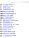
On the rear side of TRX4S you find a 6-pin mini-DIN-connector. for connection of a packet-radiocontrollers (TNC) or other modems. The pins are assigned as follows:
Pin 1: modulator, output of TNC
Pin 2: ground
Pin 3: PTT
Pin 4: data, input of TNC
Pin 5: +10 volt (current limited)
6-pin Mini-DIN connector,
Pin 6: RSSI-DCD output
outside view to the case
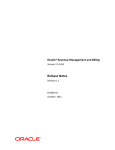
Cable between TRX4S and TNC
The wiring of all 5-pin DIN connectors of SYMEK TNC is the same:
Pin 1: modulator, output of TNC
Pin 2: ground
Pin 3: PTT
Pin 4: data, input of TNC
Pin 5: not connected
5-pin DIN-connector at TNC
The cable between TNC and TRX4S has to be as follows: :
TRX4S
6-pin mini-DIN
Signal
TNC
5-pin DIN
Pin 1
Pin 2
Pin 3
Pin 4
Pin 5
Pin 6
modulation
ground
PTT
demodulator
RSSI-DCD
+10 V
Pin 1
Pin 2
Pin 3
Pin 4
N.C.
N.C.
Page 10
TRX4S-G
Signals from and to the modem
Description of the inputs and outputs of the data connector of TRX4S. All signals refer to ground (Pin
2).
Modulation-input (Data in) Pin 1
Here, the data output of the modem is connected. The radio is adjusted, that the proper modulation
deviation is reached at 0.5 volt (peak to peak) modulating voltage. (equals 180 mVeff (effective). This
is valid for 9600/19200 baud narrow as well as for 76/153 kbaud wide band mode. The deviation can
be adjusted with trimmers inside the TRX4S, but we recommend to adjust the proper output level at
the modem.
The input impedance of TRX4S is 22 kΩ. If you have capacitors in series with this input, make sure
they have a capacity of 22 µF or more. Otherwise, the low frequencies are not properly modulated.
The input is free from dc, so an additional coupling capacitor is not necessary and even disadvantageous. The dc voltage across the modulation input may vary from –5 to +5 volt. If higher voltages
are present, connect a additional capacitor in series.
The frequency range of the modulating signal reaches from 5 to 10000 Hz (narrow mode) and from
50 Hz to 90 kHz (wideband mode). The spectrum outside this range is suppressed by the modulation
amplifier. The lowpass filters are switched automatically according to the wide/narrow selection.
Receiver output (Data out) Pin 4
The TRX4S uses two different if amplifiers and demodulators for narrow and wideband operation.
According to the setting, one of these two outputs is switched to pin 4 (data out) of the modem connector.
The demodulator-outputs are buffered by a lowpass amplifier and have a very low output impedance.
The output resistance is 220Ω in series with a 22 µF capacitor. With an external load of 1 kΩ this
results in a low corner frequency of approximately 10 Hz. Do not connect a modem with lower impedance or add capacitors in series. Otherwise the output bandwidth would be reduced.
The output is dc-free and decoupled by a capacitor. A external dc voltage of –5 to +5 volt may be
applied.
The frequency range of the output signal goes from few Hz up to 30 kHz (narrow) or from 50 Hz to
100 kHz (wide band mode). (with high impedance load)
The output voltage depends on the deviation of the received signals and is approximately 0,5 voltpp
(peak to peak) (180 mVeff (RMS) and cannot be changed / adjusted.
Transmitter keying (PTT) Pin 3
The PTT-pin shows + 5 Volt when receiving (open circuit). If it is pulled to ground (by the modem or
by a switch), the transceiver starts transmitting immediately.
To keep the time from PTT-line going low to transmitting short, this input should be pulled directly to
ground without series resistors. . The transmitter is keyed as soon as the voltage at pin 3 goes below
2 volt. The pull-up-resistor to 5 volt has a value of 47 kΩ. A low pass against radio-frequency interference with 200 kHz corner frequency is built-in.
Carrier signal detection output (RSSI-DCD) Pin 6
As soon as the rf input signal at the antenna input of TRX4S exceeds an adjustable level, the green
DCD led at the front of TRX4S lights. Simultaneously, pin 6 of the modem connector is pulled to
ground (low).
The rf signal level, at which the RSSI-DCD reacts, may be adjusted by two separate trimmers for
narrow and wide mode inside the TRX4S. The trimmer are pre-adjusted for detection of signals
TRX4S-G
Page 11
exceeding 0,5 µV antenna input voltage in narrow and wideband mode. Note: If much noise is present at the receiver input (QRM, QRN or by additional noise of a preamplifier), the trigger level of
RSSI-DCD has to be adjusted to higher levels.
The output is an open collector output, capable to switch up to 16 mA to ground. The maximal permissible voltage is 30 Volt. Caution: this output is not protected against overload.
10 volt external supply (+10V) Pin 5
For supply of external low power circuitry, the internal 10 volt supply is present at pin 6 of the 6 pin
mini-DIN connector. To avoid damage by overload or short circuit, a resistor of 600 Ω is in series with
the output. So, the current drawn is limited to few mA. A microphone amplifier or similar circuitry may
be supplied from this output without problems.
Avoid permanent short circuit of the output. The short circuit current is 10v / 600Ω = 16 mA.
Remote-Control connector'
Here, you may connect a remote control circuitry. The following control functions are accessible via
this connector:
•
•
•
•
•
power supply (ground, +5 volt)
serial interface (5-Volt RS232) for remote control
up and down keys
3-wire interface for 7-segment-display and mode display (power, narrow/wide)
12,800 000 MHz ttl output of the reference oscillator
Power supply, fuses
The power is applied via the 2 wire cable, supplied with the TRX4S. The 2 pin connector is a standard AMP universal mate-n-lok no. 350777 type, the 2 pin plug for the cable is used with two female
crimp contacts AMP Mate-N-Lok No. Type 163306-4. The connector is good for up to 25 amp and
cannot be reversed in polarity.
The 12v dc power must not be reversed in polarity. If the power is applied with the wrong polarity, a
fuse inside the TRX4S will blow and has to be replaced.
For replacement, use only a 6,3 A fuse (20 x 5 mm) with medium fast characteristic. Never short
circuit the fuse by a wire. Never use higher current types. The fuse is found directly near the power
inlet and can be easily accessed by opening the TRX4S bottom cover. Take care not to damage the
speaker wires when opening the case.
To make sure that there is no voltage drop on the supply cable, you have to use wires with sufficient
diameter. With only 0,1 Ω total resistance of the supply cable, there would be already a significant
voltage drop of 0,5 volt, but the maximum output power is only possible with 13,0 volt supply across
the power input of the TRX4S.
Inside the TRX4S, there is a low-ESR electrolytic capacitor with 180 µF, which cannot work a
smoothing capacitor for low quality power supplies. . The power source has to supply 13.5 Volt with
permanent 6 A and 8 A peak current. The low-cost CB-radio power supplies with so-called '6/8 A
power capability' will quickly overheat, when the transmit/receive ratio exceeds 20%. In many cases,
the open circuit voltage of those power adapters exceeds 15 v. The ac filtering / smoothing of the
output voltage is not perfect, which causes in 100 Hz amplitude modulation of the fm carrier. The
power supplies designed for amateur radio transceivers (13,5V 12A) have much more power reserve
and are well suited for use with TRX4S even when transmitting for longer time. Of course, you may
use a car battery for supplying the TRX4S. Take care to use wires with adequate cross-section. .
Page 12
TRX4S-G
Operating hints
TX-Delay setting
The real TX-delay of TRX4S is 1 ms or less. Watch the following points when setting the parameter
'T' at your TNC:
•
TNC: the extremely short delay-time cannot be programmed with most of the packet-radiocontrollers available today (1999). With TNC2H or other TNC2 (Z80) derived TNC, the TX-delay
can be programmed in multiples of 10 ms only. T 0 is always too short, T 1 means already 10
ms delay and is much too long. The TNC3 allows programming the TX-delay in 1 ms steps. In
addition, a TX-delay of 0 can be set and a preamble of up to 16 flags may replace the T setting
and gives a delay, which is proportional to the baudrate. (TNC3-Firmware 1.8 and later).
•
partner station: when setting the transmit-delay you have to observe, that this time is not only
required for your own transmitter to start operating but also for the receiver of the station, you
are in contact with for switching off its the transmitter completely, switching on its receiver up to
full sensitivity and getting its receiving modem synchronised. If you work with a simplex
digipeater which needs 50 ms to switch from transmit to receive, you have to consider this. If
not, the remote receiver will loose the fast answers from your TNC and has to wait for a repeated transmission. The remote station will show all your packets in monitor mode except the
first one, which came too early.
•
The transmit filter of a G3RUH-modems needs some bit preamble until valid data is sent. The
receiver of those modems needs some clock cycles as well to synchronise and lock the clock
recovery circuit. Those delays depend on the baudrate and become shorter as baudrate rise.
Recommendation: With TNC2H and TNC3/TNC31 the minimum TX-delay of T 1 can be set. If there
is a problem, check if the slow receiver of the remote station is the cause and increase TX-delay until
the problem disappears.
TRX4S-G
Page 13
TECHNICAL DESCRIPTION
Technical data of TRX4S
(valid for 1999 version C of printed circuit
board)
Dimensions: without case, without cooler: W= 163 mm, D= 103 mm, H= 29 mm, weight 0,5 kg.
Without case, with cooler: W=163 mm, D=103 mm, H=70 mm, weight 1,5 kg
Power supply: 12 volt dc (11...16 V) reception: 250 mA; transmit max. 6 A,
2-pin AMP receptacle. Fuse 6,3A slow inside the case (fuse 20x5 mm). 13 v required for
full transmit power of 25 watts. Typical values at 12,5 v :
RX: 0,27A; TX 3 W: 2,2 A; TX 6 W: 2,6 A, TX 12 W: 3,5 A; TX 20 W: 5,0 A.
Frequency range: Standard adjustment: 430 - 440 MHz
Frequency drift / error: typ. ± 2 PPM (= ± 1 kHz), max. ± 5 PPM (= ± 2,5 kHz),
Channel spacing: 12,5 kHz
Temperature range: 0 to 50 C.
Programming: via rs232-serial interface (9600 Baud, 8 Bit, NO Parity), 8-pin RJ45 receptacle. For
every channel, the transmit frequency, receive frequency, transmit power and mode may
be defined and stored. Reading of signal strength in dBm and temperature is possible.
Connection of a remote control unit is possible.
Frequency setting: any 16 frequencies may be programmed and stored in TRX4S. Selection with
up-down buttons inside the transceiver. 7-segment channel display.
Over-temperature protect: transmitter will be disabled above 60 to 65 C temperature of the power
amplifier.
Reference oscillator: 12,800 MHz ± 5 PPM
Antenna switch: 3 power pin diodes.
Useful packet data rate: max. approx. 50 packets (256 Bytes each) or 100 packets (100 Bytes
each) per second.
Receiver:
Page 14
Sensitivity: 0,2 µV at 50 Ω (12 dB SINAD, narrow-mode)
Maximum input signal: without destroying the input:
in band (430-440 MHz): +13 dBm = 20 mW = 1 v rf voltage
< 400 MHz, > 470 MHz: +33 dBm = 2 Watt = 10 Volt rf voltage
Audio amplifier: 0,5 W at 8 Ω, 3,5 mm speaker jack,
built in miniature speaker. The speaker is not disabled when transmitting.
So, the transmitted signal can be heard (simplex mode)
Data-output: 0,5 voltpp, low impedance, 6-pin mini-DIN-connector
Mirror frequency suppression: 506 MHz and 364 MHz: >70 dB
Signal detection (rf-DCD): two (narrow/wide) separately adjustable
triggers show if a rf signal is present. RX-on-delay: Delay from 'PTT = high' until reception:
< 2 µs
Wideband mode:
selectivity: ± 300 kHz: >60 dB, stop band: >110 dB
AF-bandwidth: 50 Hz to 80 kHz
dynamic range: -120 dBm = 0,2 µV to –40 dBm = 2 mV
Narrow mode:
TRX4S-G
selectivity: ± 35 kHz: >90 dB, stop band: >110 dB
AF-bandwidth: 10 Hz to 10 kHz
dynamic range: -125 dBm = 0,1 µV to –50 dBm = 1 mV
Transmitter:
Output power: programmable 3/6/12/25 watt at 50Ω
(with supply voltage below 13 v only 20 watt)
Efficiency: typ. 5,5 A / 13 V = 75 watt input at 25 w output. η= 35 %
Duty cycle: depending on ambient temperature and cooling conditions,
a average transmitter power of 12 watt (25 Watt at 50% duty cycle) is allowed. Permanent
(100%) transmission at full power requires forced air cooling. (fan) )
Power regulation: the output power is kept constant to ±0,2 dB within the total frequency
range
Mod-input: 0,5 Voltpp at 22 kΩ, separate low pass amplifiers for wide and narrow mode
Wideband mode: audio bandwidth: 30 Hz to 80 kHz, TX-delay (PTT low to full output
power – 1 dB): 50 µs
Narrow mode: audio bandwidth: 5 Hz to 15 kHz, TX-delay: 100 µs
Carrier suppression at the transmit frequency when in receive mode: infinite, no spurious
signal present.
Harmonic and spurious signal suppression: below -70 dB(c)
Transient emissions: at keying with 10 Hz: (50 ms TX, 50 ms RX): <- 40 dB (adjacent
channel), <-50 dB (500 kHz from carrier), <-60 dB (2 MHz distance), referred to carrier and
channel bandwidth (wide).
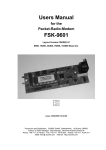
Interface cable for serial rs232 interface
The serial cable to the computer supplied
with TRX4S. . You plug it into the 9 pin male
connector of the PC. The cables and connections are the same as used with
TNC31S.
TRX4S
For serial (rs232) interfaces, modern computers uses the small 8 pin rj45 connectors
instead of the bulky 25 pin sub-d types.
Cables and adapters are available in most
computer-hardware shops everywhere.
Here some explanation to this new technique:
rj45 pin 3 = transmit data from TRX4S to
computer, output of the TRX4S
rj45 pin 6 = transmit data from the computer to TRX4S, input of
TRX4S
rj45 pins 4+5 = common ground
As the rj45 connector is not soldered to a cable but fixed by using a
special tool, the cable cannot be made by hand. But there are inexpensive ready made cables available in every computer shop. They
are called 'ISDN-cable' available screened or without screening.
(ISDN S0 bus cable for German ISDN standard wall outlets.). For
expansion of the cable length, there are small adapters available
with a female contact at each end. Sometimes, the cables have only
4 or 6 of the 8 pins wired. This is no disadvantage, as the TRX4S
uses only the centre 4 pins no. 345 and 6. The outer pins 1,2,7 and
8 are not connected.
TRX4S-G
RJ-Connector, rear view.
Only pins 3,4,5 and 6 are
used
Page 15
The cables are available as: 8-wire flat cable / modular-cable with rj45 connector, ISDN-cable rj45,
patch cable 1:1 connected, cable with 8 pin western-connectors. If you find similar cables with
smaller 6 or 4 pin connectors, as used with other telephone applications, you may use them as well.
Screened cables are much more expensive, but provide better suppression of radio interference.
The both connectors are mounted in a way, that the latches of the connectors are on the opposite
sides of the (flat) cable. So, the sequence of the pins remain unchanged (see picture).
Caution: There exists cables with so-called 'roll-over-connection'. With those cables, pin 1 is connected with pin 8, pin 2 with Pin 7 etc. Since introduction of ISDN, those roll-over cables are unusual.
With the PC serial interface COM1 there is in most cases a 9 pin male connector found at the rear of
the computer. For COM2, you will find also a 9 pin or in many cases a 25 pin male connector. When
using COM1 to connect your mouse, you will use perhaps COM2 for the TRX4S. To connect the
modular cable with the rj45, you need the adapter supplied with the transceiver. Here the list which
describes how to built such an adapter. (RJ-connector as shown in the picture, view the adapter from
the rear side.):
1) rj45 pin 3 (black wire) goes to sub-d 9 pin 2 (or sub-d 25 pin 3) Signal: RxD from TRX4S to PC.
2) rj45 pin 4 (red wire) goes to sub-d 9 pin 5 (or sub-d 25 pin 7) Signal: ground
3) rj45 pin 6 (yellow wire) goes to sub-d 9 pin 3 (or sub-d 25 pin 2) Signal: TxD from PC to TRX4S.
4) cut the remaining wires directly at the rj45 connector (pins 1= blue, 2= orange, 5= green, 7= brown
and 8= white/grey. You will need them for wiring the hardware handshake lines of sub-d connector.
5) click all 8 wires into the sub-d connector body. Caution: as soon as you hear the 'click', the jack
cannot be removed again.
5a) For 9 pin female sub-d, you put green in pin 1, black in 2, yellow in 3, grey/white in 4, red in 5,
brown in 6, blue in 7 and orange in 8. 9 remains empty.
5b) For 25 pin female sub-d, you put yellow in 2, black in 3, orange in 4, blue in 5, brown in 6, red in
7, green in 8 and white/grey in 20. All others remain empty.
6) short circuit the hardware handshake by removing the insulation of the 5 open ended wires and
solder the blue and orange wires together.
7) solder the brown, green and grey/white wires together.
8) use heat shrink tube to insulate the bare wire joints and complete the adapter by closing the case.
Make sure, the rj45 block is completely latched in the adapter case.
Terminal-programs (set-up)
The serial interface (COM) of PC has to be set up as follows:
baudrate:
parity:
bits/character:
Xon/Xoff, protocol:
RTS/CTS handshake:
stop bits:
9600
N (none)
8
off
off
1
How to set these parameters depends on your terminal program. In most cases, the setting is stored
in a configuration file and restored automatically when starting the program.
Configuration of TERM 10.36 (ms-dos program by DL5FBD)
On the disc, which is supplied with TRX4S, you find a simple terminal program TERM.exe, and the
corresponding configuration file TERM.cfg. You may run the program directly from the disc. It uses
(with the term.cfg) the following settings:
Page 16
TRX4S-G
COM-Port
baudrate
word length (Wortlänge)
parity (Parität)
stop bits
handshake
duplex (echo)
character guard time (Zeichenschutzzeit)
linefeed guard time (Zeilenschutzzeit)
e
g
h
i
j
k
l
u
v
1
9600
8
K (keine)
1
K (kein)
H (Halbduplex, Echo ON)
25 ms
250 ms
With the ALT-P key, the configuration may be changed easily. With the r key, the changed settings
may be stored in term.cfg permanently. It has been found, that the program behaves somewhat
different with linefeed on different computers.
Configuration of 'Terminal' (Windows 3.11)
With Windows 3.11 comes a terminal program called simply 'Terminal'. Find it on your hard-disk as
C:\Windows\Terminal.exe and execute the following settings: (maybe the English version of Windows
Terminal uses other expressions as I expect)
1. menu 'settings – data transfer is set to COM2, 9600 baud, 8 bit, no parity, no protocol, 1 stop bit.
2. menu 'settings' – text transfer is set to 'transfer line by line' with 3/10 sec linefeed guard time /
line delay.
3. menu settings – terminal-emulation is set to e.g. TTY-general
4. menu 'settings' – terminal-settings activate the local echo.
The settings are stored as a .trm file, e.g. TRX4S.trm. This file will be found in C:\Windows\ and can
be dragged and dropped on the desktop in any program group of Windows 3.11. Double-clicking
the icon (labelled TRX4S), will immediately start 'Terminal' with the proper configuration.
Configuration of Hyperterm (Windows95/98)
With Windows 95/98 comes a fine new terminal program called 'Hyperterm'. You can start it in programs – accessories – communication – Hyperterm with the following settings: (referred to the German version of Hyperterm)
1. When starting, Hyperterm asks for some prefix-number. Type any number you like.
2. The program asks 'new connect?'? Type e.g. TRX4S and select one of the funny icons.
3. In the window 'connect via' “ you select the COM-Port, e.g. COM2 - OK
4. As 'communication settings' you select 9600 baud, 8 data bits, no parity, 1 stop bit, no protocol.
OK
5. With 'file - characteristic - settings you may set the ASCII-configuration : Switch on the options
'transmitted lines end with linefeed' and 'echo input characters locally (local echo). A linefeed
delay (guard time) of 250 milliseconds is recommended, the ASCII-settings remain unchanged.
6. The settings are stored. The file TRX4S.ht, which contains the settings, can be found normally in
C: \programs\accessories\hyperterminal and may be drag-and dropped onto the desktop. As
soon as the symbol with the label TRX4S is clicked or double clicked, Hyperterm will start with
the correct settings.
With Windows98 and Hyperterm, we did not succeed in switching the local echo on. With Windows95
there was no problem.
TRX4S-G
Page 17
Commands of the TRX4S firmware 1.1
The TRX4S contains a microcontroller, which communicates with the PC by a serial rs232 interface.
The commands, which are understood by the microcontroller are explained here. Every line has to
end with a return-character ($13). The number and position of the characters within a command
string has to match exactly as described here.
Designations:
n
T, R
F
P
channel identifier {0, 1, 2, 3, ... 8, 9, A, B, C, D, E, F}
decimal figure for transmit (T) and receive (R) -frequency {0, 1, 2, 3, ... 8, 9}
operating mode: N = narrow, all others = wide {N, W}
transmit output power: 4=25 watt, 3=12 watt, 2=6 watt, other: 3 watt, {1,2,3,4}
the remaining characters (Z, K, S, R, V and the decimal point) must be used exactly as indicated.
Storing a record
With this command, a channel data record is stored in EEPROM of TRX4S. After the command has
been executed, the record is read out immediately and returned as acknowledgement to the PC.
input:
reply:
Zn=TTTT.TTTT F P RRRR.RRRR
Zn=TTTT.TTTT F P RRRR.RRRR
Note: the records are not checked for proper syntax. Wrong and nonsense characters after the '=' are
stored as given. This may cause unwanted and unexpected settings of the transceiver when selecting the channel later. In most cases, the wrong frequency setting causes the PLL oscillator not to
lock. If the 'transmit'-led remains off when keying the transceiver, in most cases a wrong programmed
channel record is the cause. The same is true for the receiver ('receive'-led doesn't light).
Note: The Z-command changes the contents of the frequency memory, but does not change the
current frequency and mode of the transceiver.The new frequency becomes not valid until the channel n (via remote command or by pressing up/down keys or at power-on) is selected again.
Reading a record
With this command, a channel data record may be read out of the TRX4S EEPROM.
input:
reply:
Zn=?
Zn=TTTT.TTTT F P RRRR.RRRR
Reading all 16 records
With this command, a listing of all 16 channel data records is read out of TRX4S-EEPROM.
This command is executed automatically, when the 'up' key is pressed at power-on.
input:
ZX=?
reply:
Z0=TTTT.TTTT F P RRRR.RRRR
etc. until
ZF=TTTT.TTTT F P RRRR.RRRR
after each line, there is a short delay of 250 ms.
Page 18
TRX4S-G
Note: If the frequency of a channel had been changed before with the Z-command, the result of the
ZX=? command will change as well. BUT the real frequency and mode settings remain unchanged
until the current channel is selected again (see above).
Selecting the current channel
With this command, one of the 16 possible channels is selected to be the current channel. . The
channel-number-display, the transmit and receive frequency, mode and power are changed according to the newly selected channel. The number of the channel is stored immediately.
The command has the same effect as changing the current channel by pressing the up and down
keys.
input:
reply:
KX=n
Kn=TTTT.TTTT F P RRRR.RRRR
Reading the current channel-number
With this command, the number of the current channel is read out:
input:
KX=?
reply:
KX=n
Reading the s-meter (signal strength)
The antenna rf input voltage is read in dB with reference to 1 mW. (dBm). The calculation of the
displayed value in dBm and the internal measurement uses a lookup-table, stored in EEPROM.
There exists two separate tables for narrow and wide mode, as the RSSI-voltages are derived from
two different if-demodulators for each mode. The minus-sign is omitted, so a display of 90 means -90
dBm.
input:
R0=?
reply:
R0=DDD
Temperature display (output power)
The temperature of the transmitter power amplifier is measured by a sensor and can be checked via
the serial interface. The temperature is displayed directly in degree Celsius. The calculation of the
displayed value in Celsius and the internal measurement uses a lookup-table, stored in EEPROM. .
By changing this table, it is possible to change the reading to Fahrenheit or other units, however the
displayed values have to be in the range of 0 to 255. The pins M830-M831 has to be connected by a
100 kΩ resistor for temperature measurement.
input:
S0=?
reply:
S0=DDD
The S0= command will immediately read the actual temperature value, converted in Celsius. This
value may, caused by the coarse resolution of the A/D converter, show steps of 3 to 5 degree. For
more accurate measurements, you should make 10 or 100 readings and calculate the average value.
This makes the reading slower but quite exact. In TRX4S terminal program TRX4TERM, there is a
floating average value calculated: The most recent reading contributes only 1 % to the result, the
contribution of the old readings is 99%.
Optional: If the pins M831-M832 are connected by a 100 kΩ resistor, you can measure the transmitter output power instead of temperature. . Problem: As the transmitter is not keyed permanently, you
will read 0 watt while receiving. The transmit power can be displayed in dBm, the calculation of the
displayed value in dBm and the internal measurement uses a lookup-table, stored in EEPROM.
There are two tables in EEPROM: one for temperature measurement (0400H-04FFH) and one for
power measurement (0300H-03FFH). Which of the tables is used depends on the value of a switch
variable in EEPROM. (See EEPROM-programming).
TRX4S-G
Page 19
Display firmware-version number
input:
reply e.g.:
VERS
SYMEK TRX4S CPU4 V1.1
Show serial number
In the TRX4S, a serial number and the date of manufacture are stored. Please do not alter this data,
it won't be possible to change the values without knowledge of the proper algorithm code. The memory, where the data is stored, cannot be written by the program TRX4TERM. When starting
TRX4TERM, the serial number is read and displayed.
Error messages of TRX4S, syntax
The TRX4S uses only the lower 7 bit of all input characters. Lowercase characters (from 60H to
7BH) are converted to uppercase by subtraction of 20H. .
The data input is not checked completely for correct syntax:
•
The content of a channel-data record DDDD.DDDD F P DDDD.DDDD is not checked. You may
input any nonsense, which will result in wrong and unexpected results later.
•
The commands are not checked completely. The microcontroller checks only if the command is
unequivocal, e.g. the version display command VERS will be caused by all inputs starting with V
and having a length of 4 characters, so you may type VOLT or V0=? with the same result.
•
The mode is set to 'narrow' only when a N or n is given in the channel record string. All other
figures are interpreted as wideband mode commands.
•
The output power is defined with the figures 2, 3 and 4. All other characters are interpreted a 1
(lowest power setting) within the channel record string.
•
The decimal point is not interpreted. Any other character or the comma are allowed as well. The
TRX4S interprets only the least significant bits of the figures of the frequencies. The input
430,25000 instead of 0430,2500 not correct. It will not cause an error but leads to an unwanted result.
The following input errors are recognised: :
ERROR
ERROR
ERROR
ERROR
ERROR
ERROR
1
2
3
4
5
6
Page 20
Line length over 27 characters
Command line length has not exactly 4 characters length
Unknown command with 4 characters length (not Z, V, S, R, K as first character)
Unknown command string with 27 characters length (Z is not the first character)
EEPROM address or EEPROM-byte no correct hexadecimal code
EEPROM address exceeds 07FFH
TRX4S-G
SERVICE-ADJUSTMENTS
Programming of EEPROM-memory
The EEPROM contains a list with the records for the 16 channels, information about the last selected
channel number, four lookup-tables for conversion of s-meter and temperature measurement and a
flag for switching the temperature and output power tables.
The records containing the channel frequency information should be written with the normal user
command Zn=... , the lookup-tables should remain unchanged.
For special applications it is possible to access the EEPROM directly, e.g. for the first set-up. There
exists a command for writing every byte into each address of EEPROM..
Definition:
EEPROM-address (hexadecimal) value range: {0000 to 07FF}
EEPROM-data (1 byte, hexadecimal) value range: {00 to FF}
XXXX
YY
POKE: write byte to EEPROM
command:
reply:
YY will be stored at address XXXX of EEPROM.
contents of address XXXX is YY.
XXXX YY
XXXX YY
PEEK: read byte in EEPROM
command:
reply:
read address XXXX of EEPROM.
contents of address XXXX is YY.
XXXX
XXXX YY
EEPROM memory map
Address
0000...0017
0018...002F
etc. until
0168...017F
0180
0181
0182...01FF
0200...02FF
0300...03FF
0400...04FF
0500...05FF
0600...07FF
decimal
(0-23)
(24-47)
(360-383)
(384)
(385)
(386-511)
(512-767)
(768-1023)
(1024-1279)
(1280-1535)
(1536-2048)
description
24 Byte ASCII chan. 0 e.g. "0433.7000 N 2 0433.7000"
24 Byte ASCII chan. 1 e.g. "0434.2125 W 2 0434.2125"
24 Byte ASCII chan. F e.g. "0433.7000 N 2 0433.7000"
number of the channel, which was selected last (00 to 0F)
table select: (00= temperature or 01= power table is used)
manufacturer's information etc. do not alter!.
conversion-table for meter, narrow mode
conversion-table for meter, wide mode
conversion table for power/temperature, used when (0181H=01H)
conversion table for power/temperature, used when (0181H=00H)
free memory space, may be used by external software.
Useful formulas (see page 46): (Z0=50 Ω, Uin = voltage across Z0 in volt, PdBm = power in dBm)
U in = Z 0 ⋅ 1mW ⋅ 10
TRX4S-G
PdBm
10
;
PdBm
U in2
= 10 ⋅ log
Z 0 ⋅ 1mW
ln (x )
; log( x ) =
ln (10 )
Page 21
INTERNAL ADJUSTMENTS
Opening the case
Before one of the following adjustments is done, you have to open the TRX4S case first. Locate the
case bottom up (cooler down) and loosen all 10 screws of the bottom plate (which is now oriented
towards you with speaker and display), do not totally remove the screws. Gently pull the cover up by
using the screws as handle. If the cover is very tight, loosen also the screws at the top panel.
The loudspeaker is fixed at the bottom plate. Take care not to destroy the speaker cable. . The
speaker wires can be disconnected near the external speaker connector.
The big heatsink can be removed. Just remove the six screws with a hex driver. Caution: use the
same screws and all washers when reinstalling the heatsink. The screws must not intrude more than
exactly 5 mm into the transceiver's base plate. A shorter intrusion length is unfavourable as the
thread could be pulled out.
If the TRX4S should be used with a different heatsink, you may use any flat surface. The position of
the six M4 screws are arranged symmetrically on the 100x160 mm base panel, The distance from the
long edge is 25,0 mm, from the short edge 20,0 mm and centre (80,0 mm).
Total disassembling the TRX4S
Better don't try to disassemble the TRX4S. Even for experienced technicians with a well equipped
workbench it will be difficult to make repairs at the TRX4S. . Send the TRX4S to the manufacturer,
where technicians with special knowledge of all secret tricks will care about your transceiver. Consider the risk of unintentional damage when trying to do repairs.
Page 22
TRX4S-G
If it is necessary to disassemble the TRX4S, proceed as follows:
1.
The heatsink may be removed or not.
2.
Remove cover with speaker.
3.
Remove all nuts of audio and squelch-pots and of all connectors.
4.
Remove 7 screws at front and side and pull the U-shaped front panel gently towards you. The
perforations in the front panel are etched with 0,05 mm precision and there is no margin. Take
extreme care not to bend the panel. The corners of the U-shaped side panels must not be bent,
otherwise the panel may break. Put the to a safe place.
5.
Remove the remaining 3 screws on the rear side, poll the rear panel gently away. Do not bend!
6.
The TRX4S must not be operated (transmit mode) without base panel. There exists the risk to
overheat the power amplifier module. or the voltage regulator. . When adjusting the TRX4S, the
influence of the base panel was considered (capacity and screening effect). With correct adjusted over-temperature protection, the TRX4S may be operated for tests without case at full
power, as long as the base plate is correctly installed.
7.
Replacing the power amplifier: Unsolder the 5 pins (remove all solder and pull wire gently up).
Remove the two M4-screws of the module and pull it to the side out. If the module is too tight,
loosen the M2,5 screws around the module. To reinstall the amplifier, execute the steps in reverse order. The pins of a new amplifier have to be cut to 5-6 mm. The mounting screws of the
module must never protrude the base panel. Use adequate washers! Do not overtighten (Aluminium).
8.
Disassembling the printed circuit board: Remove the voltage regulator and all 11 M2.5 screws.
Be extremely careful: if the screwdriver slides out the screw's head, you will destroy the SMD
components nearby. Finally take the board away from the panel. Take care not to loose the
spacers.
9.
Assembly in reverse order. Do not overtighten the screws. The voltage regulator has to be
mounted using a mica insulating and washer. . First reinstall the rear panel and the front panel
later. Finally, install the nuts on the connectors and potentiometers again.
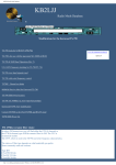
Adjustment of the transmit power
There are 5 miniature trimmer for adjustment of transmit power. Be very careful when adjusting: you
might damage the tiny components and the power amplifier by setting a too high power limit. The
trimmer have no mechanical limit, it is difficult to recognise the position of the trimmer.
The trimmers are near the power amplifier. (see picture)
The transmit power was pre-set to 3-6-12-25 watt.
With low supply voltages (below 13 volt) the maximum power of 25 watt may be not reached.
There exists 5 trimmer resistors:
•
•
•
•
•
R560 PWR max.:
R557: PWR0:
R555: PWR1:
R554: PWR2:
R553: PWR3:
TRX4S-G
power limitation, max. power setting
adjust step 1 power 1 (3 Watt), minimum transmit power
adjust step 2 power (6 Watt)
adjust step 3 power (12 Watt)
adjust step 4 power (25 Watt)
Page 23
Adjustment transmit power:
Required: a power-meter (1 to 35 watt) with 50 Ω
dummy load is connected to the antenna connector of TRX4S. Note: even short RG58 cables will
cause a significant power drop due to attenuation.
1.
program the power to step 4 (25 Watt), key
the transmitter an read the power-meter.
2.
turn PWR3 (R555) to maximum clockwise
position (min. resistance, max. power)
3.
adjust PWR max. (R560) for a reading of 30
watt. Turning clockwise increases power. The
setting will limit the output power and protect
the amplifier. Avoid prolonged transmissions
at powered above 25 watt.
4.
program power step 1 (3 Watt), key the
transmitter and adjust the power to 3 watt by
turning trimmer PWR0 (R557). Clockwise
rotation increases power.
5.
program power step 2 (6 Watt), key the
transmitter and adjust the power to 6 watt by
turning trimmer PWR1 (R553).
6.
program power step 3 (12 Watt), key the
transmitter and adjust the power to 12 watt by
turning trimmer PWR2 (R554).
7.
program power step 4 (25 Watt), key the
transmitter and adjust the power to 25 watt by
turning trimmer PWR3 (R555).
Position of TX-power trimmer
R560 (PWR0) defines the lowest possible power
at step 1 (3 watt). Power below 2-3 watt may be
difficult to set. With step 2, 3 and 4 (6, 12, and 25
w) you may set any powers between 3 and 25 watt
as desired, e.g. 3, 6, 9 and 18w. The output power
is regulated and constant within 0.5 dB over the
total frequency range of TRX4S transmitter.
The typical output power capability of the amplifier
module used is 35 to 40 watt at 13,8 volt supply
voltage. It is however possible to set the trimmers
to get much more power as 25 watt. This results in
excessive heating of the amplifier and may cause
progressive reduction of the power capability or
total failure after weeks or months of operation.
Audio
Page 24
TRX4S-G
Adjusting of temperature limitation
Near the power amplifier module, you find a SOT23 miniature temperature sensor. Via the A/D converter the temperature of this sensor can be displayed by software. . Further, there exists a circuit,
which will shut down the transmitter when overheated. If the PTT-input is pulled to ground and the
red 'TX'-led doesn't light, check if there is a overheating condition. (If the transmitter is cold, an
alternative cause might be that the PLL doesn't lock because of a wrong programmed frequency).
The temperature protection is set to 62 ± 2 C. When increasing this limit, there is a risk of overheating and damage. Especially the power amplifier module may be damaged by excessive temperature.
Inside the TRX4S you find a miniature trimmer for adjusting the maximum permissible temperature. .
Be very careful when adjusting. The trimmer has no mechanical stop and the position cannot be
recognised optically.
The trimmer R832 is located behind the audio and the squelch pot between two filters. (see picture)
Setting the temperature limit:
The temperature sensor is pre-calibrated. So, it is sufficient to measure the output voltage of the
sensor to determine the temperature. For more precise adjustments, a oven would be required.
You need a high impedance voltmeter. Measure the voltage at Pin 2 of U250 (right top) or at the tap
of trimmer R832 (left top). Adjust the following settings:
Temp. Max °C
Measure Volt
(20)
40
45
50
55
60
62,5
65
70
75
80
(2,81 V)
3,00 V
3,04 V
3,09 V
3,13 V
3,17 V
3,19 V
3,21 V
3,25 V
3,29 V
3,33 V
The precision achieved by this way of measurement is approx. 5° C. Theoretically, you may
set the trimmer to voltages from 2,97 to 3,60
volt, which corresponds to a temperature range
from 38 to 125 C.
Adjusting of rf carrier detection
The receiver-IC's of TRX4S have a RSSI-output (radio
signal strength indicator), where you can measure a
voltage, which is proportional to the rf input level (in
dB). There exist two separate RSSI-signals, one for
wide and one for narrow bandwidth signal reception.
If the RSSI-signal exceeds a pre-set level, the green
'RSSI-LED will light. Simultaneously, pin 6 of the 6-pin
mini-DIN data-connector is pulled low.
With the trimmers R263 (DCD level narrow) and R264
(DCD level wide), the trigger voltage for carrier detect
can be adjusted. separately for narrow and wide
TRX4S-G
Page 25
mode. The trimmer can be found near the 6 pin mini-DIN connector inside the case.
Procedure: apply an unmodulated carrier with the desired strength to the antenna input and adjust
the trimmer R263 (DCD level narrow) and R264 (DCD level wide) so, that the led just flickers. For
adjusting DCD-level narrow you will have to select a frequency in narrow mode, equivalent for 'wide'setting.
The setting does not influence the reception of data signals in any way. Only the function of the green
DCD-led and the DCD-output (pin 6) is affected.
The adjustment range goes from 'permanent DCD' (ccw) to 'never DCD detect' (clockwise). Between
the limits, the adjustment is approximately linear with the logarithm of the input power. The trigger
point may be adjusted to any input signal strength within the dynamic range from –120 dBm = 0,2 µV
to –50 dBm = 1 mV (narrow) or –115 dBm = 0,5 µV to –40 dBm = 2 mV (wide).
If the DCD is set to a very low level, the presence of additional noise (QRM, QRN) or the use of an
preamplifier may increase the idle input signal level and cause a permanent DCD-display. Set the
level to a higher level to consider the additional signal.
Adjustment of the modulation (deviation)
The audio input voltage (mini-DIN-connector pin 1) for appropriate deviation is set to 0,5 volt peakpeak. If your packet-radio-controller supplies more or less voltage, you should adjust the signal at the
TNC but not at the TRX4S.
The modulation input sensitivity can be adjusted separately for narrow and wide mode. The adjustment range goes from few mV up to approx. 0,8 Vpp (narrow) or 3 Vpp (wide). Do not use too small
signal levels in order to reduce additional noise.
The trimmers can be found behind the mini-DIN-connector (see picture)
For best setting in narrow mode, adjust R241 so, that you measure 0,6 Vpp at point M250.
For best setting in wide mode, adjust R211 so, that you measure 4,0 Vpp at point M250.
Alternatively, you can use a test receiver with deviation-meter to set directly the correct deviation.
Note: too much input voltage causes excessive deviation on the transmit signal. This will cause
problems due to distortion at the receiving station if the bandwidth of the receiver is smaller as those
of the transmitted signal.
Adjustment of the modulation (compensation)
The transmitter of TRX4S is modulated using a
two-point modulation circuit. The high frequency
parts of the modulating signal is applied directly to
the varicap diode of transmitter-VCO, the low
frequency parts will also modulate the reference
oscillator. So, it can be made sure, that the PLL
does not compensate the low frequency parts of
the input signal and that modulation down to very
low audio frequencies is possible.
With trimmer R253 you may adjust the ratio of the
two modulation indices for the two modulators. .
You find it between the 7-segment-display and the
audio volume potentiometer.
Page 26
TRX4S-G
For adjustment, apply a square wave signal (0,5 Vpp) with approx. 150 Hz frequency to the data input
of radio and watch the demodulated signal at the data output of a reference test receiver. (with
appropriate bandwidth capability)
If the reference quartz modulation is not enough, (trimmer R253 turned too much ccw), you find a
deviation from pulse flatness. After the pulse edge, the pulse of the received signal drops.
With too much modulation applied to the reference quartz, (trimmer R253 too far cw), you find
too little modulation of reference quartz
too much modulation of reference quartz
also a deviation from pulse flatness, but the voltage continues to rise slow after the edge.
If the compensation is adjusted properly, the rising and falling edges are at the same voltage level
and the pulse top is not tilt.
Adjustment of the reference quartz
Transmit and receive frequency are derived from two quartz oscillators: the reference quartz determines the VCO-frequency, (approx. 350 MHz) and is primary responsible for precision of the transmit frequency. and stability. The 60,3 MHz oscillator participates also in generating the correct frequency.
-6
The frequency drift of the oscillators of TRX4S is approx. 2·10 . Adjustment makes only sense, is a
-7
frequency counter with a precision of 2·10 or better is available. We recommend counters with
temperature controlled quartz oven or counters with external synchronisation to a radio frequency
standard (DCF77, WWV etc).
The frequency of the reference oscillator may be measured at pin 7 of the microcontroller IC or
(without opening the case) at pin 9 of the REMOTE-connector. With trimmer R312 (see picture) the
frequency may be adjusted to 12 800 000 Hz exactly. The TRX4S should be in receive mode and no
modulation signal must be applied. Adjust the frequency to ± 1 Hz precision, which corresponds to
30-40 Hz error at 430 MHz operating frequency.
Alternatively, you may measure the frequency of one of the both VCO. Program any frequency (e.g.
435,000 MHz) and subtract the if frequency of 71,000 MHz. The resulting RX-VCO-frequency (e.g.
364,000 MHz) can be measured at M639 (behind the antenna connector, see picture 'output power
adjust upper right).
TRX4S-G
Page 27
Do not adjust the reference oscillator by measuring the transmit frequency only, as this frequency
depends on the precision of the other oscillator as well.
Adjustment of the local 60,3 MHz oscillator
After precisely adjusting the reference quartz to 12.8 MHz, you
may adjust now the 60,3 MHz oscillator by measuring the transmitter output frequency. Tuning coil L400 (see picture 'compensation'), this oscillator frequency can be set within a narrow
range to the correct reading. The 1,5-fold of the quartz frequency
can be measured while transmitting at M425 (90,450 MHz). You
find this point directly near the white transmit mixer, 10 mm
behind the audio volume potentiometer.
Adjustment of TX-VCO
With a TX-VCO control voltage of 2,5 volt, the VCO should
oscillate in the centre of the band. So, if the centre frequency is
properly adjusted with C330 (at the end of the VCO-line, behind
the squelch pot, see picture lower right) the voltage at M325 (see
picture, middle left) will read 2,5 volt The transmitter may be
disabled by miss-tuning L406 while measuring the VCO frequency.
Adjustment of RX-VCO
With a RX-VCO control voltage of 2,5 volt, the VCO should
oscillate in the centre of the band. So, if the centre frequency is
properly adjusted with C621 (at the end of the VCO-line, in the
centre of the board, see picture upper) the voltage at M620 will
read 2,5 volt.
Adjustment of quadrature coil
The coils L721 (narrow) and L750 (wide) are responsible for
proper fm-demodulation. Adjustment is easy: connect an oscilloscope to the data output of the receiver and adjust for optimal
symmetry of the receiver noise signal. The receiver input remains open or is terminated with a 50 Ω resistor.
If-filter adjust
We recommend not to do any adjustments at the if filters .
L710 and L711 are simply adjusted to maximum RSSI reading in
narrow mode
The coils L665 and L682 have to be adjusted carefully. They are
responsible for proper input and output matching of the 71 MHz
quartz filter. Improper filter matching results in changing the
amplitude and phase response of the filter, causing excessive
distortion to the data signal. . With a suited sweeper you may
Page 28
TRX4S-G
optimise the amplitude of the if filters, but not the phase response. It is a good idea to adjust the filter
matching by observing the eye pattern at the receiver output. While receiving a 153 kbaud signal, you
watch the eye pattern and adjust L665 and L682 for optimal symmetry and eye.
Adjustment of 90,45 MHz stages
The 60,3 MHz oscillator is set to the exact frequency by adjusting L400 (see above).
L406 is adjusted with the transmitter keyed up for sufficient drive of the frequency divider U410. If the
coil is not adjusted, the divider doesn't work and there will be no 30,15 MHz signal present at the
dividers output.
The 90,45 MHz is generated by tripling the 30,15 MHz at the output of the divider. At M425, the coils
L420 and L422 are adjusted to maximum signal. The band filter at 90,45 MHz (L415 / L416) is set to
maximum output too.
Adjustment of transmitter driver 435 MHz
The mixer U430 generates the 435 MHz transmit signal, which will be amplified to 0.5 watt in the 4
stage driver amplifier. The attenuators between the amplifiers make sure, that the amplifiers work
absolutely stable with constant load and perfect matching.
For coarse adjustment, the power regulation of the power amplifier is disabled. If the regulation would
be active, a change in driver power would be compensated by the regulation and you could not
measure a difference when tuning the driver stages. Set the transmit power to level 4 (25 watt) and
turn the corresponding trimmer R555 to maximum power. Now reduce the output again by setting the
power limit (R560) to 5-10 watt output power at the antenna connector. Now, the power regulation is
disabled. The value of the output is now proportional to the driver input and you can do the adjustments for the driver stages without problems. Be sure to set the trimmers to the old settings after the
adjustment of driver.
Do not turn the brass screws of the helical filters. A readjustment is difficult. If all filters are tuned to
maximum power at centre frequency, you will find a significant power drop at the ends of the band.
Try to adjust the filters in a way to achieve flat response over the total frequency range but steep
edges at the band limits. After the adjustment to maximum power at centre frequency, turn one of the
three filters some MHz up and one some MHz down to get a flat response within the total frequency
range and a sharp cut-off at the frequency limits.
Trimmers C455 and C467 are set to maximum output at centre frequency.
After successful coarse adjustment, re-set the power limit and regulation back to the previous value.
For fine adjustment of the amplifiers you won't need a wattmeter. If the power regulating trimmers are
set to 3-6-12-25 watt with a limit at 30 watt, the measurement of the regulated bias supply of the
driver stage in the module will do. Program the power range to level 2 or 3 (6 or 12 watt) and measure the voltage at the middle pin of IC U560 (voltage regulator at the base plate next to the amplifier
module. The lower the voltage, the lower is the amplification of the driver to achieve the selected
output level and the higher the driver stage power level. Adjust the drivers now to minimum reading
of the regulated bias voltage at U560.
If the power regulation doesn't work stable at low power levels (3 watt), the driver power might be too
high. Reduce driver power by setting the filters of the driver stages off resonance.
TRX4S-G
Page 29
Adjustment of final amplifier and lowpass filter
The 5 coils L523, L528, L530, L532 and L545 are part of the 3 stage lowpass filter and the transmitreceive antenna switch. with the pin-diodes CR541, CR545 and CR528. Adjustment of these filters is
not necessary. The attenuation of the filters in the pass band cannot be reduced. The harmonics of
the transmitter are sufficiently suppressed and cannot be reduced by changing the filters.
The same is true for the coils L530 and L545 in the receiver input path.
Update of firmware
If it becomes necessary to change the firmware, stored in the microcontroller, gently pull the 18-pin
IC U800 out of the socket and insert the controller with the new firmware.
Disabling the 7-segment display
The current drain of the 7-segment display is approximately 15 mA (the complete receiver needs
approx. 250 mA). Directly in front of the display you find a jumper to disconnect the display power
supply to save 15 mA.
Switching temperature / power reading
The microcontroller of TRX4S has two analogue inputs. One of them is used for measurement of the
RSSI voltage, the other is normally used for reading the voltage across the temperature sensor, but
can be set to power measurement as well.
Problem: you may read the temperature at any time. But measuring the transmit power makes only
sense if the transmitter is keyed while measuring. As the PTT is controlled only by the attached
packet-controller, which does not communicate with the TRX' microcontroller, measuring the real
output power is difficult. For this reason, the default setting of TRX4S is temperature display.
With the default setting, S0=? will read the temperature of the amplifier. But it is possible to change
the setting to power reading if necessary. Two steps are necessary:
1. The input of the A/D converter is connected to the temperature sensor by the jumper M830/M831
by a 100 kΩ miniature resistor. Remove the resistor (outer contacts of the 3 pin jumper) and connect
M831 and M832 (middle contact and outer contact towards front) by the 100 kΩ resistor. Now, the
A/D converter input is connected to the RF measurement rectifier. .
2. For temperature and power measurement calibration, there exists two different lookup tables in
EEPROM.. Which of the two tables will be used when executing the S0=? command, depends on the
value stored in address 0181H of EEPROM. This memory location is default set to 01H, the controller
uses the table stored at the addresses 0400H to 04FFH to convert voltage into degree Celsius. If the
jumper is changed to power measurement, the byte in 0181H has to be set to 00H using the 'POKE'
command. Normally, the conversion table for power measurement is empty and has to be calibrated
first.
Page 30
TRX4S-G
Measuring points
For set-up and adjustment, the following measuring points can be used:
M100
M101
M102
M103
M104
M105
M106
M250
M260
M261
M303
M325
M425
M430
M432
M440
M450
M604
M620
M639
M747 / M746
M820 / M821
M830
M831
M832
TRX4S-G
+ 5 volt permanent
+ 5 volt transmit
+ 5 volt receive
+ 12 volt fused, unregulated
+ 10 volt permanent
+ 4,8 volt low noise supply of VCO
+ 5 volt permanent, input of t/r switching-FETs
modulation after switchable low pass amplifier
RSSI-signal from narrow demodulator
RSSI-signal from wide demodulator
PLL 12,8 MHz after prescaler (transmitter)
VCO-control voltage (transmitter)
90,45 MHz +3 dBm (transmit)
TX-VCO 369,7-379,7 MHz +7 dBm
TX-mixer output 430-440 MHz
TX after first amplifier 430-440 MHz
TX after second amplifier 430-440 MHz
PLL after prescaler (receiver)
VCO control voltage (receiver)
RX-VCO 359-369 MHz +7 dBm
connector for internal loudspeaker
jumper for display supply
temperature sensor output voltage
A/D converter input for power or temperature measurement
relative output power dc-voltage
Page 31
Remote-Control connector
At the front, you find a 10-pin receptacle 'remote' to control all functions of TRX4S.
You need a 10 pin (1/10 inch or 2,5 mm spaced) male connector. A possible remote control unit may
be attached to the front of the TRX4S by spacers with M2.5 screws, which fit into the base and cover
plate threads and with 10 pins to connect the remote control jack.
The following signals are available:
Ground, + 5 volt, clock for power supply of a remote control unit
Pin 10 (oriented to centre of the front panel) is connected to ground, pin 8 supplies 5 volt from the
internal voltage regulator of TRX4S. The maximum permissible current drawn is 150 mA.
The reference oscillator (12,800 MHz) is present at pin 9. Here you may attach a frequency counter
for adjusting the transceiver frequency reference, but the buffered signal may be used for supplying a
clock to an external processor of a remote control circuitry. A separate oscillator for such a circuit
should be avoided, as this may cause additional interfering spectral lines within the receivers frequency range.
Push button functions 'up' and 'down' for channel selection
The signals for switching the channels up and down are accessible at the remote control connector
pins 4 (down) and 5 (up). Note: the keys are not switched to ground but to + 5 volt!
3-wire interface for output of 7-segment-display, power-setting, mode
With every channel change, a 16-bit word is output at the three pins 1 (data), 2 (clock) and 3 (enable). Here, normally a shift register (serial in parallel out. e.g. 74HC595) is connected. After output
of a hi or low signal at pin 1 (data), this information is shifted into the register by a low to high transition of the pin 2 (clock). After all 16 bit have been output in that way, the total information is latched
with the rising edge of the pin 3 (enable) line. Now, all 16 bit are available at the parallel output of the
shift registers.
Here the description of the 16 bit (shown in consecutive order first to last)
1. Bit
2. Bit
3. Bit
4. Bit
5. Bit
6. Bit
7. Bit
8. Bit
(not used)
(not used)
(not used)
(not used)
power level 4
power level 3
power level 2
mode narrow
9. Bit
10. Bit
11. Bit
12. Bit
13. Bit
14. Bit
15. Bit
16. Bit
7-segment: DP
7-segment: g
7-segment: f
7-segment: e
7-segment: d
7-segment: c
7-segment: b
7-segment: a
If only one 8-bit shift register is used, the bits 1 to 8 of the information are lost. The register will show
only the last 8 bit (9 to 16) which can be used for a external 7-segment display. In most of the applications, the bits 1-8 are not necessary and may be omitted. A BCD to 7-segment decoder is not
necessary, as the 7-segment patterns are stored in and generated by the microcontroller of TRX4S.
With bits 5 to 8 you may control LED's to display the current output power level and wide/narrow
mode. The bits are sent with approx. 100 kbit/s in a synchronous mode (11.0 µs per bit). To built a
simple decoder, you may copy the shift register circuit of TRX4S
Page 32
TRX4S-G
serial asynchronous 9600 baud interface for programming etc.
Using pins 6 (serial output) and pin 7 (serial input), you can execute all commands of TRX4S as
described on page 18. The interface is parallel to the external rs232-interface, but the signal levels
are different. (voltages referred to pin 10, ground)
•
serial output (pin 6): serial 9600 baud signal from TRX to remote control unit.
Idle (stop bit): HI (5 volt), data (start bit): LO (0 Volt). 1 start bit, 1 stop bit.
•
serial input (pin 7): serial 9600 baud signal from remote control unit to TRX4S.
Idle (stop bit): HI (5 volt), data (start bit): LO (0 Volt). 1 start bit, 1 stop bit.
For sending data, a open-collector output will do. The input is de-coupled to the external rs232
by a diode. Note: external programming via rs232 and programming via the remote control connector cannot be done simultaneously. If pin 7 is pulled to + 5 volt with a resistor (> 47 kΩ), the
remote control unit can read the data, which is transferred from the rs232 to the TRX at the serial input of the TRX remote connector. In idle state, pin 7 must be open or pulled to + 5 V. If
pulled to ground, the external rs232 programming won't be possible.
DETAILED CIRCUIT DESCRIPTION
We won't describe every stage of the circuit. Most of the TRX4S circuits are common amplifiers,
filters or oscillators. We want to explain only those circuits, with special or unusual functions.
Reverse polarity protection: the safest protection against reverse polarity of the supply voltage
would be a diode in series with the supply. As there would be a voltage drop of 0,3 to 0,7 volt, this
solution would be unfavourable. We use a reverse biased parallel diode with 40 A current capability
to blow the fuse. Using fuses with higher current rating results in the risk to blow the diode first and
so destroying the transceiver when reversing supply voltage.
PTT-input: the PTT-input switches the transmitter via a 74HC132 Schmitt-trigger. As soon as the
voltage at the PTT input drops below 2 Volt, the transceiver will switch to transmit, rising above 3 volt
will switch to receive again. When not connected, there will be a voltage of + 5,0 volt at pin 3 of the
data connector. The PTT-input is protected by a 200 kHz lowpass filter against rf interference. When
keying the transceiver by an open-collector output, this low pass filter will cause a delay of the receive-transmit switching of approx. 5 µs, the switching from transmit to receive will take 50 µs. If the
PTT is controlled directly by a ttl-output, the delay will be constant 5 µs in both cases.
Transmitter supply voltage: The 5 volt transmitter supply voltage is switched by a FET-switch with
5 amp current capability and a low Ron of 60 mΩ. The FET switches immediately. It would not be
possible to have the switch before the voltage regulator, because the settling of the common 7805
regulators needs too long (about 1 ms and more). The transmitter supply is only switched on if the
TX-PLL is locked. A unlocked PLL would oscillate on a undefined frequency and result in interference
or unwanted transmissions. The led 'TX' lights if the TX is supplied with 5 volts and PLL is locked.
The driver stages and the pin-diode antenna switch are not affected by the locking condition of the
PLL. If the TX-frequency is programmed wrong, the PLL won't lock and remains disabled.
Receiver supply voltage: The receiver is switched on after transmission with a little delay to make
sure, that the transmitter is totally shut of when reception starts again. As with the transmitter, the
RX-supply is only switched on (green RX-led lights), when the RX-PLL is locked. If the RX-frequency
is programmed wrong, the PLL won't lock and the receiver remains off.
Voltage regulator for PLL: The presence of noise on the LPL's supply voltage would result in excessive phase noise (unwanted modulation) of the transmitter and receiver output. For supply of the
two PLL circuits, the normal voltage regulators are not suited. The TRX4S uses a simple transistor
for filtering the noisy 5 volt internal supply. The transistor amplifies the voltage delivered from the 5
volt supply via a lowpass filter with 0,5 Hz corner frequency.
TRX4S-G
Page 33
Power supply of the audio amplifier: The operational amplifiers of the modulation and audio
stages are supplied symmetrically with +/- 5 volt. The internal +5 volt is used as the ground for the
amplifiers, the transceiver ground is used for negative supply and a regulated voltage of 10 volt is
used for positive supply. The +10 volt come from a standard 5 volt regulator with its ground pin connected to 5 volt. The regulated 10 volt will also supply the LM386 audio amplifier for the speaker.
Switchable 90,45 MHz oscillator: A stable oscillator needs approx. 10 ms to start oscillating or to
lock on a frequency. Hence, all oscillators in a fast data transceiver have to oscillate permanently.
The problem is, that the oscillators, needed for generation of the transmit frequency, will cause a
spurious signal exactly at the receiver input frequency in simplex mode (f TX = f RX). The problem
was solved by using a 'TXD-null-oscillator': The transmit frequency is generated by mixing of the
constant PLL frequency with a 90,45 MHz auxiliary frequency, derived from a frequency divider with
a fix 60,3 MHz quartz. By switching off the frequency divider, the 30,15 and the tripled 90,45 MHz
signal vanishes completely, however, all quartz oscillators remain on. So, there exists really no spurious signal at the transmit = receiver frequency when receiving.
Diode mixers: The TRX4S uses two high quality diode mixers 'ADE13'. The local frequency input
level is as high as +7 dBm = 5 mW to achieve excellent large signal capability of the receiver and a
high level intercept point. (IP3: 17 dBm = 50 mW)
Amplifiers general: All rf amplifiers use monolithic amplifiers type ERA3. These amplifier IC are
suited for up to 3 GHz, have a input and output impedance of 50 Ω, which makes matching easy. The
gain of approx. 20 dB per amplifier is reduced by pi-attenuators between the stages to 14 to 17 dB to
improve stability and matching of the amplifiers. With a noise figure of 3,8 dB, these amplifiers may
be used as sensitive preamplifier as well, but more important is the excellent large-signal capability of
these amplifiers. (IP3 = 23 dBm = 200 mW). The amplifiers may be driven with up to 20 mW (1 volt)
rf at the antenna input without damage.
Power amplifier: As power amplifier, the Toshiba M57729 is used. According to the datasheet, it is
capable to output 45 dBm = 35 watt rf power, typical values of much more have been measured. With
44 dBm = 25 watt transmitter output power, there is enough power margin to keep the output constant over the total frequency range. The harmonic frequencies, measured directly at the module
output are 20 dB below the carrier (24 dBm = 0,3 W).
Lowpass output filter and antenna switch: The harmonic frequencies of the transmitter signal are
suppressed by a lowpass filter. The attenuation of the first harmonic frequency at 870 MHz with a
third order filter is approx. 60 dB. This gives a total suppression of 80 dB = -36 dBm = 250 µW referred to the carrier. The attenuation of the third harmonics is even better. In series with the transmit
signal path, there is a high power pin diode, which disconnects the transmitter output from the antenna when receiving. The diode is suited for rf power up to 100 watt and has a rf-resistance of 0,5 Ω
at 30 mA control current. The antenna signal passes a third order filter on its way to the receiver
input. When transmitting, the rf from the transmitter is switched to ground with two pin-diodes. The
high attenuation of this switch makes sure, that the receiver input is not overdriven or even damaged
by the high power transmitter levels. In most transceivers, only one diode is used for keeping the
transmitter power away from the receiver input, which results in a much stronger rf signal at the
sensitive preamplifier input.
Transmit power regulation: Directly at the power amplifier module output, the rf is rectified by a
capacitor and fast low-capacity Schottky diode. The rectified rf voltage is filtered and controls via a dc
amplifier and a switchable voltage divider the reference input of a programmable voltage regulator
LM317T, which supplies the drivers. When rf output power drops, the voltage across the divider
decreases and the supply voltage of the drivers increases to give more power. With 4 trimmers, the
voltage divider can be switched to program one of 4 pre-set power levels. When in receive mode,
the voltage divider is pulled to +5 volt to shut down the driver supply completely.
VCO circuit: The VCO frequency is generated with a newly developed IC, giving a signal with perfect spectral purity at a high power level. For inductor, there is no coil used but a λ/4 semi-rigidresonator. This avoids interference and acoustic-mechanical influences to the VCO tank circuit and
has better temperature stability compared to wounded coils.
Page 34
TRX4S-G
Data-output (demodulation): The outputs of the both demodulators (wide, narrow) are selected by
an analogue switch to pin 4 of the data connector. When transmitting, both switches are open and
the output is disabled. Pin 4 is dc decoupled by a 470 Ω resistor in series with a 22 µF capacitor. .
Data input (modulation): The data input (Pin 1) goes to two low pass amplifiers with different corner
frequencies. for wide and narrow. The outputs are switched to the modulating circuits when transmitting. In receive mode, the modulation is disabled. Otherwise, the reference oscillator, which is
used for reception too, would be affected by the data in signal, causing interference to the receive
data.
Squelch: The AF-noise of the narrow demodulator is filtered at 11 kHz and rectified with CR739. If
the noise amplitude exceeds a certain value, which can be set with the squelch pot R733, the audio
signal is switched to ground by an analogue switch.
Audio-amplifier: The control speaker is driven by the amplifier IC LM386. With 10 volt supply voltage this amplifier delivers 0,7 Watt into a 8 Ω load. The built-in speaker is disconnected if an external
speaker jack is plugged-in.
Comparator for rf-DCD: The RSSI-signals of the two receivers are compared to an adjustable dc
voltage (trigger level). The output of one of the comparators controls only the green led 'RSSI-DCD',
the other is the pin 6 of the data connector. The trimmer for setting the DCD trigger and the RSSIoutputs of the if amplifiers are switched by analogue switches.
A/D converter for RSSI, temperature and power measurement: The microcontroller possesses two
analogue compactor inputs. One of the comparators is used for RSSI measurement, the other for
temperature or power measurement. The non inverting input of the comparators is connected to a 22
nF capacitor, which is charged to +10V by a 100 kΩ resistor within 2 ms time. The capacitor is discharged by a FET to zero volts and the microcontroller measures the charge-time, which is needed
until the voltage across the capacitor becomes equal to the voltage to be measured The time is
measured as a value within the range between 1 and 255 and converted by a lookup-table in to the
displayed value. (dBm. °C)
RS232-interface: the UART (asynchronous transmitting and receiving) is performed by software in
the microcontroller. The baudrate (9600 baud, 1 start, 1 stop bit, no parity) is fixed and cannot be
changed. For level translator, the well known MAX232A is used. With its built-in charge pump, this
driver generates the +/- 10 volt. The serial input and output is filtered with a r-c-r lowpass filter to
reduce rf interference with the serial interface connector. The rs232-input is pulled to -10v with a 10
kΩ resistor to give a 'low' signal (stop bit polarity) when no computer is connected. This is important
to control the TRX4S controller via the external rs232 interface parallel to the remote control connector. As the charge pump of the MAX232 uses high current and high frequency pulses for generating the +/- 10 volt, the 5 volt supply of the MAX232 is decoupled from the transceiver by a 10 kHz
lowpass filter.
Temperature sensor and over-temperature protect: At the power amplifier module's mounting
screw, there is a tiny KTY92 temperature sensor with a nominal resistance of 2000 Ω at 25 °C. The
-3 -1
temperature coefficient of this semiconductor sensor is 7,9 *10 K . Hence, at 70 °C the resistance
increases to 2780 Ω, the voltage across the voltage divider R830 – U830 rises accordingly. As soon
as the voltage reaches the value, set by trimmer R832, the op amp U250 pulls the transmit enable
signal to ground via transistor Q835 and disables the transmitter immediately. After cooling down, the
transmitter returns back to normal operation.
Channel display: The channel number is displayed by a 7-segment-display TDSR3160 (common
cathode). With 1,5 kΩ segment resistors the total current is 4 to 16 mA depending on the figure
displayed. The display is controlled by a 8 bit serial-parallel-converter (shift register), the 7-segmentcode is stored in the microcontroller firmware.
EEPROM: The 8 pin SMD-EEPROM has a storage capability of 16 k Bit = 2048 byte. The addresses
from 0000H to 017FH are used for storing the 16 frequency records, 0200H to 03FFH contains the
TRX4S-G
Page 35
lookup tables for measuring conversion. The EEPROM is accessed by a 2-wire interface. The firmware allows to read from and write to any address by the PEEK and POKE commands.
REGULATIONS, ETC.
All copyrights on firmware, PCB-layout and schematics of TRX4S are reserved to SYMEK GmbH or
Ing. Büro Kumm, Stuttgart. Parts of the circuit are covered by patents pending.
Parts of this manual may be published if there is a reference in the bibliography. It is our concern to
contribute to packet-radio by offering new and powerful equipment and to inspire many radio amateurs by this fascinating technique
When properly used, the TRX4S complies with the regulations of German EMVG and bears the CEsign. A German BZT-approval, which would be necessary for commercial use does not exist. So, the
use of the transceiver is limited to licensed amateur radio operators as transmitter.
The user will need special knowledge on electronics and communication techniques for operating the
transceiver, as it is demanded to pass the amateur operators licence exam. The transceiver and the
description are not made to be used by people without technical knowledge. .
For proper use, it is necessary to connect the transceiver to a suited power supply, to connect a
suited signal source for modulation, which meets the requirements described in this manual. , to
connect a suited antenna with according feeding cables. For not to deteriorate the EMV-values, you
must connect only those subassemblies to the remote-control connector, which are recommended by
the manufacturer. additional modules have to be connected using the original connectors. Make sure,
that the cables connected are not interfered by strong electro-magnetical fields (speaker, modulation,
power supply, antenna).
The user is - as with any other amateur radio transmitter - obliged to make sure, that no person is
endangered by the radio frequency power, produced by the transmitter. If you are not sure about the
existing regulations for operating a transmitter or high frequency equipment, see your local authorities for telecommunications. For Germany, see the information published by Regulierungsbehörde
für Post und Telekommunikation (http://www.regtp.de).
The actual German law allows everybody to own or trade with the TRX4S transceiver. This is also
true for using the TRX4S as receiver only. . If used as transmitter, the responsible user has to have a
permission (e.g. amateur radio operators licence).
We are nor liable for any damage, which might be caused by the use of the transceiver, nor for erroneous information or misprints in the manual.
Page 36
TRX4S-G
SCHEMATICS, PART LOCATION
Location of the parts (left half)
TRX4S-G
Page 37
Location of the parts (right half)
Page 38
TRX4S-G
Schematics TRX4S (AF, TX, power-supply)
TRX4S-G
Page 39
Schematics (receiver, control)
Page 40
TRX4S-G
WHAT TO DO IF THE TRX4S DOES NOT
WORK?
Here some common user errors: :
Malfunction: PTT is keyed but the red 'TX'-led remains off. No transmit power.
Cause: wrong transmit frequency programmed or amplifier too hot.
Malfunction: 'RX'-led remains off, no reception
Cause: wrong receive frequency programmed.
The TRX4S design is proven good. The components are reliable for industrial use, the printed circuit
board is of first class quality and all transceivers are tested thoroughly. However, there is a chance
that the equipment would fail.
If you have done any modifications with TRX4S, please make sure that these modifications are NOT
the cause for the malfunction and remove all modifications again. If there are changes or attempts to
repair made, the warranty claim is void.
For the following damage there is no claim for warranty repair:
•
Overload of power supply by over-voltage (over 16 volt), causing failure of the voltage regulator
or the power amplifier module.
•
Destruction caused by reverse polarity of power supply or by use of a wrong fuse.
•
Destruction of the power amplifier, caused by misadjusted over-temperature protection or use
of unsuited rf load (e.g. open antenna connector), bad SWR)
•
Too high input level at receiver input, damage of the preamplifier
•
Destruction of serial interface caused by over-voltage at the rs232-connector
•
Destruction of the audio signal amplifiers caused by over-voltage at the data-connector
•
Destruction of the audio power amplifier caused by over-voltage or short circuit at the speaker
connector
•
Destruction of components caused by over-voltage at the REMOTE-connector.
•
Any kind of mechanical damage
The warranty period is 1 year from purchase, excluded are damages caused by the customer.
Please give us a detailed description of the failure and what has happened before the failure occurred. The repair could be done faster and more easy.
We hope, you enjoy the use of the TRX4S high speed data transceiver.
TRX4S-G
Page 41
INDEX
10 volt external supply (+10V) Pin 5 12
60,3 MHz oscillator 27, 29
7-segment display 30
7-segment-display 35
90,45 MHz oscillator 34
A/D converter 25, 35
ac filtering of supply 12
acknowledge of record 18
adapter rj45 15
adapter rj45-sub-d 16
adjust 90,45 MHz stages 29
adjust driver stages 435 MHz 29
adjust lowpass filter 30
adjust of VCO centre frequency 28
adjust quadrature coil 28
adjust TX power 24
adjusting the 60,3 MHz oscillator 28
adjustment of referencequartz 27
adjustment of transmit power 23
adjustments 21
AF-bandwidth 14
amateur radio operators 36
amateur-radio transmitters 36
ambient temperature 15
Amiga 8
amplifiers 34
analogue switch 35
antenna 6
antenna connector open 41
antenna switch 14, 34
Apple 8
ASCII-configuration (Hyperterm) 17
assembly 23
Atari 7
attempt to repair 41
audio amplifier 14, 34, 35
audio input voltage 26
base panel 23
baudrate 7, 35
buttons 'up' and 'down' 32
BZT-approval 36
Cable (data) 10
cable PC-TRX4S 15
calibration tables 30
capacitor, 12v supply 12
car battery supply 12
Carrier detection (RSSI-DCD) 11
carrier suppression TX 15
case, opening 22
CB 12v power supplies 12
CE-sign 36
channel data record 18
channel display 35
channel identifier 18
channel selection 8, 19
channel settings 8
channel spacing 14
channel-selection 6
charge pump 35
check of record syntax 18
Page 42
com-interface 7
command 8
commands of TRX4S firmware 18
commercial use 36
communication between terminal and
transceiver 8
comparator for rf-DCD 35
compensation 26
config-file of terminal program 16
configuration file TERM.cfg 16
connect via (Hyperterm) 17
connecting cable TNC-TX 10
connection of remote control 6
control voltage (VCO) 28
controller 30
conversion tables 21
CONVERSION VOLT, W ATT, DBM 46
cooling 15
copyright 36
corner frequency (modulation) 35
current channel 8, 19
damage 36
damage of the preamplifier 41
damage, mechanical 41
data connector 6
data input (modulation) 35
data transfer 17
data-output 14
data-output (demodulation) 35
dB (µ
µ V) 46
dBm 46
dc across data-input 11
dc decoupling (data output) 35
dc input supply 12
DCD Level 25
DCD-output 26
default set-up 6
defect 41
demodulator 10
demodulator (narrow) 35
deviation 11, 26
deviation meter 26
dimensions physical 14
diode-mixer 34
disabling the 7-segment display 30
disassembling the TRX4S 22
disc 7
distortion 26
driver stages 435 MHz 29
driver supply 34
dummy load 24
duty cycle 15
dynamic range of DCD 26
dynamic range rf 14
EEPROM 18, 35
EEPROM address 20
EEPROM-programming 21
EMVG-regulations 36
ERROR 20
error messages 20
Fahrenheit 19
fan 15
FET-switch 33
filter capacitor 12v supply 12
filter, amplitude and phase response 28
TRX4S-G
firmware version display 20
fm-demodulation 28
frequency 18
frequency counter 27
frequency divider 29
frequency drift / error 14
frequency memory 18
frequency of reference oscillator 32
frequency of reference quartz 27
frequency of the VCO 27
frequency of VCO 27
frequency precision 27
frequency range 14
frequency range (data out) 11
frequency range of data input 11
frequency setting 14
front panel 6
front panel removing 23
fuse, 12 volt supply 12
guard time 8
handshake 7
harmonic suppression 15
heatsink 22
Hyperterm 8
Hyperterm (Windows95/98) 17
if filter coils 28
if-adjust 28
input errors recognition 20
input impedance (data) 11
input signal maximum 14
input voltage (antenna) 19
input voltage (audio) 26
inputs and outputs of TRX4S 11
installing the heatsink 22
interface cable 7
interface f. 7-segment-display 32
interface parameter 7
interface to computer 6
interference 36
interference, rs232, filter 35
intermodulation, 3rd intercept 34
isdn-cable 15
key 'up' 9
keying the transmitter 33
knowledge, special 36
knowledge, technical 36
KTY92 35
large signal capability 34
law - permission 36
led 'TX' 25
level translator rs232 35
limitation of TX power 23
linefeed delay (Hyperterm) 17
local echo 17
lookup-table 19
low audio frequencies 26
low corner frequency (data out) 11
low pass amplifiers, modulation 35
lowercase characters 20
lowpass amplifier 11
lowpass antenna filter 34
lowpass filter adjust 30
manual 36
manufacturers information in EEPROM 21
TRX4S-G
matching the 71 MHz quartz filters 28
matching TNC to TRX4S 26
MAX232A 35
maximum temperature 25
measuring points 31
memory map of EEPROM 21
memory, EEPROM 35
mica insulation 23
microcontroller 18, 30, 35
microphone amplifier 12
miniature trimmer 23
mini-DIN-connector 10
minimum output power 24
minimum TX power 23
mirror frequency 14
misprints 36
mode 18
mode wide/narrow 8
modem connector 11
modems 10
mod-input 15
modular-cable 16
modulating voltage 11
modulation 10, 26
modulation amplifier 11
modulation input sensitivity 26
modulation-input (Data in) 11
monolithic amplifiers 34
new connect (Hyperterm) 17
noise at the PLL supply 33
noise figure 34
number of current channel 8
oscillator frequency drift 27
output impedance (data out) 11
output power 18, 34
output power display 19
output power measurement 30
output power TX 15
output voltage 11
overheating 25
overheating the power amplifier 23
overload at rf input 34
over-temperature protect 14, 23, 35, 41
over-voltage 41
packet rate 14
packet-radio-controller 26
packet-radio-controller (TNC) 10
parallel diode 33
part location 37
patents 36
peek: read byte in EEPROM 21
permission 36
phase response of if filter 28
pi-attenuator 34
pin 6 of modem connector 11
pin diode 34
pin-diode antenna switch 33
poke: write to EEPROM 21
polarity, reverse, protect 33
polarity, supply-voltage 12
potentiometer 23
power 24
power amplifier 24, 34
power amplifier replacement 23
Page 43
power consumption 30
power display 30
power drain, supply 14
power limitation 23
power margin 34
power regulation TX 15
power supply 12, 14
power-cycle 8
power-on 8
preamplifier 34
prefix number (Hyperterm) 17
printed circuit board 23
printed circuit board version 5
programming 14
programming of EEPROM 21
protocol (Hyperterm) 17
PTT 10
PTT-input 33
pulse edge 27
pulse flatness 27
push-button 6
quadrature coil adjust 28
quartz oscillators 27
ratio of modulation 26
reaction time for transmitter keying 11
reading a record 18
reading all 16 records 18
reading the current channel number 19
reading the s-meter 19
rear of TRX4S 10
rear panel 23
receive frequency setting 8
receive only regulations 36
receiver of the remote station 26
receiver output (Data out) 11
receiver supply voltage 33
record 8, 18
reference oscillator 14, 26
reference quartz 27
reference quartz modulation 27
reference receiver 27
Regulations 36
Regulierungsbehörde für Post und
Telekommunikation 36
remote control connector 32, 35
remote-control interface 33
Remote-Control-connector 12
removing the board 23
repair 22, 41
replacement of power amplifier 23
reversed power supply damage 41
rf signal input level 25
rf signal level (DCD) 11
rf-carrier detect 25
rf-DCD 35
rf-measurement rectifier 30
rj45 connector 7
'roll-over-cable rj45' 16
rs232-interface 35
RSSI (radio signal strength indicator) 25
RSSI-DCD 10
'RSSI-DCD-led 25
RSSI-DCD-LED 11
RSSI-DCD-trigger 11
RSSI-signals 35
Page 44
RX-on-delay 14
s0 isdn bus cable 15
schematics 39
Schottky diode 34
selectivity 14
semi-rigid-resonator 34
sensitivity receiver 14
sensor, temperature 19, 35
serial interface 15
serial async. 9600 baud interface 33
serial interface (COM-port) of PC 7
serial number 20
service-adjustments 21
setting of modulation 26
setting of rf carrier detection 25
setting of temperature limit 25
setting of the 2-point-modulation 26
setting temperature limit 25
setting the current channel 19
settings (Hyperterm) 17
set-up 6
set-up of terminal program 16
shift register 32
signal detection 14
signals from and to the modem 11
S-Meter 46
software 30
spacers 23
speaker 22
speaker, external 35
spectral purity signal 34
spurious signals 15
square wave 27
squelch 6, 35
stability of frequency 27
storing of a record 18
sub-d-connector 7
supply of audio amplifier 34
supply voltage 23
supply voltage for microphone etc. 12
switchable 90,45 MHz oscillator 34
swr damage 41
symmetry 28
syntax 20
tables for A/D converter 35
technical data 14
Telix 8
temperature coefficient 35
temperature display 19, 30
temperature limitation 25
temperature range 14
temperature sensor 25, 30, 35
TERM (dos) 8
TERM 10.36 16
Terminal (Windows 3.11) 17
terminal program 7, 16
Terminal.exe 8
terminal-emulation 17
terminal-settings 17
test-receiver 26
text transfer 17
TNC31S 15
trade 36
transient emissions 15
transistor voltage regulator 33
TRX4S-G
transmit data serial 15
transmit enable 35
transmit frequency setting 8
transmit power 8
transmit power adjust 23
transmit power regulation 34
transmitter keying (PTT) 11
transmitter power measurement 19
transmitter supply voltage 33
transmitting equipment 36
trigger voltage for RSSI-DCD 25
trimmer resistors 23
TRX4S firmware 1.1 18
TRX4TERM.exe 7
two-point modulation 26
TX-delay 15
TXD-null-oscillator 34
unexpected settings 18
unknown command 20
update of firmware 30
updates 5
up-key at power-on 18
TRX4S-G
uppercase 20
use of TRX4S, proper 36
user 36
user error 41
varicap diode 26
VCO centre adjust 28
VCO of transmitter 26
VCO-circuit 34
version number 8
version of printed circuit 14
voltage regulator for PLL 33
voltage regulator LM317T 34
voltage regulator overheat 23
volume 6
VT52-Emulator 7
warranty 41
western-connector 16
wideband mode RX 14
wire diameter/cross section 12
wrong frequencies 18
Z-command 18
Page 45
CONVERSION VOLT, WATT, DBM
U
0.05 µV
0.1 µV
0.2 µV
0.5 µV
1 µV
2 µV
5 µV
10 µV
20 µV
50 µV
100 µV
200 µV
500 µV
1 mV
2 mV
5 mV
10 mV
20 mV
50 mV
100 mV
200 mV
224 mV
0,5 V
1V
2V
5V
7,1 V
10,0 V
14,1 V
17,3 V
20,0 V
22,4 V
24,5 V
31,6 V
35,4 V
50,0 V
70,7 V
Page 46
P (50 Ω )
50E-18 W
200E-18 W
800E-18 W
5E-15 W
20E-15 W
80E-15 W
500E-15 W
2E-12 W
8E-12 W
50E-11 W
200E-10 W
800E-10 W
5E-9 W
20E-09 W
80E-09 W
500E–9 W
2E-6 W
8E-6 W
50E-6 W
0,2 mW
0,8 mW
1 mW
5 mW
20 mW
80 mW
0,5 W
1W
2W
4W
6W
8W
10 W
12 W
20 W
25 W
50 W
100 W
dB (µ
µV)
-26 dB (µV)
-20 dB (µV)
-14 dB (µV)
-6 dB (µV)
0 dB (µ
µ V)
6 dB (µV)
14 dB (µV)
20 dB (µV)
26 dB (µV)
34 dB (µV)
40 dB (µV)
46 dB (µV)
34 dB (µV)
40 dB (µ
µV)
66 dB (µV)
74 dB (µV)
80 dB (µV)
86 dB (µV)
94 dB (µV)
100 dB (µV)
106 dB (µV)
107 dB (µ
µV)
114 dB (µV)
120 dB (µV)
126 dB (µV)
134 dB (µV)
137 dB (µV)
140 dB (µV)
143 dB (µV)
145 dB (µV)
146 dB (µV)
147 dB (µV)
148 dB (µV)
150 dB (µV)
151 dB (µV)
154 dB (µV)
157 dB (µV)
dBm
-133 dBm
-127 dBm
-121 dBm
-113 dBm
-107 dBm
-101 dBm
-93 dBm
-87 dBm
-81 dBm
-73 dBm
-67 dBm
-61 dBm
-53 dBm
-47 dBm
-41 dBm
-33 dBm
-27 dBm
-21 dBm
-13 dBm
-7 dBm
-1 dBm
0 dBm
7 dBm
13 dBm
19 dBm
27 dBm
30 dBm
33 dBm
36 dBm
38 dBm
39 dBm
40 dBm
41 dBm
43 dBm
44 dBm
47 dBm
50 dBm
S-Meter
S 0 –6 dB
S0
S1
S 2,3
S 3,3
S 4,3
S 5,6
S 6,6
S 7,6
S9
S9 +6 dB
S9 +12 dB
S9 +20 dB
S9 +26 dB
S9 +32 dB
S9 +40 dB
S9 +46 dB
S9 +52 dB
S9 +60 dB
S9 +66 dB
S9 +72 dB
S9 +80 dB
TRX4S-G
Datensysteme und Elektronik GmbH
Users manual TRX4S Hardware
(printed circuit version C)
issue: 1999-06-21
Manufacturing and distribution: SYMEK GmbH, Datentechnik, Ulf Kumm, DK9SJ
Address:
D-70597 Stuttgart,
Johannes-Krämer-Straße 34
Phone: +49 711 76 78 923,
Fax: +49 711 76 78 924,
Hotline: +49 711 76 54 911
e-mail: [email protected]
Internet-homepage: http://symek.com
TRX4S-G
Page 47