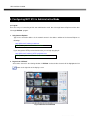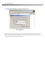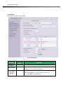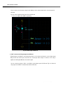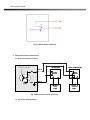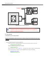
1
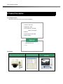
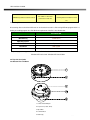
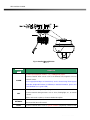
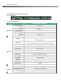
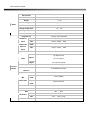
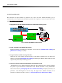
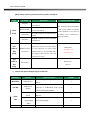
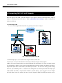
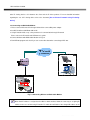
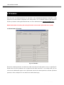
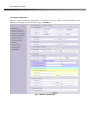
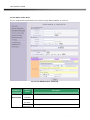
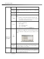
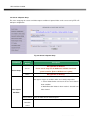
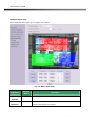
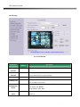
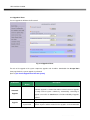
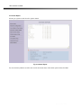
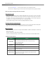
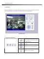
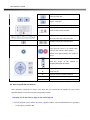
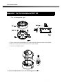
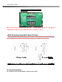
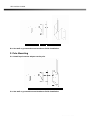
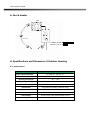
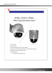
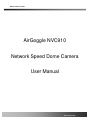
NVC 910 User’s Guide
AirGoggle NVC910
Network Speed Dome Camera
User Manual
Rev1.0(Aug.2007)
NVC 910 User’s Guide
Directions
NVC 910 series network cameras are designed for outdoor/indoor use. Don’t use NVC 910 in an environment
that exceeds the limited range.
Be careful not to cause any physical damage by dropping or throwing the NVC 910 network camera.
Especially keep the network camera out of reach from children.
Do not disassemble NVC 910 or After Service Follow-up is not possible.
Use only the AC power adapter which conforms to the specification in data sheet or optionally provided DC
power adapter with the NVC 910.
If you would like to use the NVC 910 for security, monitoring, please check the legal regulations within the
country.
Note
This equipment has been tested and found to comply with the limits for a Class A digital device, pursuant to
part 15 of the FCC Rules. These limits are designed to provide reasonable protection against harmful
interference in a residential installation. This equipment generate, use and can radiate radio frequency energy
and, if not installed and used in accordance with the instructions, may cause harmful interference to radio
communications. However, there is no guarantee that interference will not occur in a particular installation. If
this equipment does cause harmful interference to radio or television reception, which can be determined by
turning the equipment off and on, the user is encouraged to try to correct the interference by one or more of
the following measures
Reorient or relocate the receiving antenna.
Increase the separation between the equipment and receiver.
Connect the equipment into and outlet on a circuit different from that to which the receiver is
connected
Consult the dealer or an experienced radio/TV technician for help.
Rev.0.1 (Dec.2007)
2
NVC 910 User’s Guide
Warning & Caution
If you fail to read this information and
handle the product incorrectly, death or
serious injury may occur.
The unit should be installed by trained
personnel.
Always stop using when the product emits
smoke or abnormal heat.
This symbol is intended to alert the user to
the presence of un-insulated “dangerous
voltage” within the product’s enclosure that
can cause electric shock..
Never install the product in area exposed to
water, oil or gas.
Never install the product on a ceiling that
This symbol is intended to alert the user to
the presence of important operating and
maintenance (servicing) instructions in the
literature accompanying the appliance.
cannot hold its weight.
Never touch the power cord with wet hands.
Clean only with dry cloth.
Additional Warning & Caution
for NVC 910
Never install the product in extremely high or
Never move Pan/Tilt by hands.
low temperature.
causes serious damage to the camera.
It may
Never drop, hit strongly nor vibrate the
product.
Input power:
With Camera - 24V AC
18 watts at 24V AC
Never expose the product to direct sunlight
Heater:
18watts
or severe ray.
Fan:
2watts
Never touch the front glass of the product.
The heater activates at +10℃ (±5℃),
deactivates at +15℃(±5℃)
Never install the product in areas exposed to
rain or water
The fan activates at +45℃ (±5℃),
Deactivates at +35℃ (±5℃)
Rev.0.1 (Dec.2007)
3
NVC 910 User’s Guide
Revision History
Date
Rev. No
2007-12-17
0.1
Description
Creation of the document
Rev.0.1 (Dec.2007)
4
NVC 910 User’s Guide
Table of Contents
1. Introduction ......................................................................................................................................................... 7
1.1. Overview........................................................................................................................... 7
1.2. Features of NVC 910 ......................................................................................................... 7
1.3. Applications of NVC 910 .................................................................................................. 10
2. Product Description........................................................................................................................................... 11
2.1. Package Contents ........................................................................................................... 11
2.2. Preview........................................................................................................................... 11
2.3. PC Requirements ............................................................................................................ 12
2.4. Physical description......................................................................................................... 12
2.5. Specification of the analog camera module and PTZ part .................................................. 15
2.6. Quick Installation Guide ................................................................................................... 17
3. Connecting NVC 910 to IP Network ................................................................................................................. 20
3.1. Connecting to LAN .......................................................................................................... 20
3.2. Connecting to xDSL/Cable Modem................................................................................... 21
4. IP-Installer ......................................................................................................................................................... 23
4.1. Main window of IP-Installer .............................................................................................. 23
5. Configuring NVC 910 in Administrative Mode .................................................................................................. 24
5.1. Log On............................................................................................................................ 24
5.2. Basic Setup..................................................................................................................... 26
5.3. Network Configuration ..................................................................................................... 28
5.4. Wireless Configuration (This is not applicable to NVC 910 network camera)Error!
Bookmark
not defined.
5.5. User Admin & Time Setup ................................................................................................ 31
5.6. Sensor & Capture Setup .................................................................................................. 34
5.7. Alarm Device Setup ......................................................................................................... 36
5.8. Motion Region Setup ....................................................................................................... 38
5.9. PTZ Setup....................................................................................................................... 40
5.10. Encryption Set up .......................................................................................................... 42
5.11. Upgrade & Reset ........................................................................................................... 44
5.12. Status Report ................................................................................................................ 46
6. Tips for Using NVC 910 .................................................................................................................................... 47
6.1. Alarm (for Sensor input) and AUX(for Relay output) .......................................................... 47
6.2. Trouble Shooting ............................................................................................................. 50
6.3. Web Viewer..................................................................................................................... 52
Rev.0.1 (Dec.2007)
5
NVC 910 User’s Guide
6.4. How to upgrade NVC 910 firmware .................................................................................. 53
Appendix 1. On Site Installation of NVC 910 ........................................................................................................ 55
Appendix 2. On Site Installation of NVC 910 ..........................................................Error! Bookmark not defined.
Rev.0.1 (Dec.2007)
6
NVC 910 User’s Guide
1. Introduction
1.1. Overview
The NVC 910 is a state-of-the-art Speed Dome network camera which transmits synchronized video and audio
data in real time with D1 resolution at full frame rate. This is possible through MPEG4 CODEC technology, which
provides high quality video with highly compressed data streams. The NVC 910 can be connected, controlled and
monitored from a remote location through an IP connection over internet or intranet. Unlike CCTV or DVR, the
NVC 910 is easy to install and owner will experience cost and space savings in the installation owing to the state
of the art technologies embedded in the system. Based on Embedded Software Solution (Embedded Web Server,
Embedded Streaming Server, Network Protocol), the NVC 910 ensures unprecedented performance and stability
to be an ideal network camera solution for system integration solutions. NVC 910 is offered with standard
Ethernet interface.
1.2. Features of NVC 910
Vandal proof mini speed dome X Zoom
1 channel synchronized real time Video/Audio streaming MPEG-4 video, ADPCM audio.
Bi-directional audio communication
Real time audio communication between NVC 910 and Client PC
The viewer assisted recording and playback functions
Filter Changeable Type Day & Night
IP66 water-resistant
100x Zoom(10x Optical with 10x Digital zoom)
350 degree continuous rotation
Clear image of 530TV line(B/W:580TV line)
Noiseless low light image with SDNR
Day&Night with ICR
Max. 200 degree/sec Pan & Tilt speed
Max 30 frames/sec(NTSC) and Max 25frames/sec(PAL) @ D1 resolution
Full D1 Resolution with De-interlaced filter
Versatile PTZ control
Client viewer assisted PTZ control,
Dedicated virtual system controller for PTZ control on the client
Simultaneous connection & control over IP and RS485
4 Alarm sensor inputs / 2 relay outputs
Rev.0.1 (Dec.2007)
7
NVC 910 User’s Guide
Motion detection – Up to 3 motion detection zones. Arbitrary shape motion detection zone
Motion detection can initiate video recording, which is sent to the user through FTP and/or E-mail.
Resolution
- NTSC : 704x480, 352x240, 176x144. - PAL/SECAM : 704x576, 352x288, 176x144
Remote administration control
Entire operational parameter set up, Software upgrade
Rev.0.1 (Dec.2007)
8
NVC 910 User’s Guide
Detailed
Features of Speed Dome part
100X Zoom Mini Speed Dome
Hot Keys
10X Optical Zoom with 10X digital zoom
This camera supports various hot key functions
for ease of control by other controllers or DVRs.
±0.02°° dome system accuracy with 1/4
micro step
Various Surveillance Functions
By adopting 1/4 micro step and twin gear system, the dome
camera achieved 0.1° rotational accuracy. It provides excellent
precision for delicate control such as preset positions.
Auto Scan continuously repeats movement between two
preset positions with various speed and dwell time.
8 Group Tour : Up to 8 Programmable Group tours are
supported. Each group can be configured to have up to 60
preset positions with different speed and dwell time
360° Endless Rotation
165 Preset positions : Up to 165 programmable preset
positions. Each preset position can be labeled by up to 16
characters
Preset position compensation
It minimizes the effect of low frequency vibration caused by
wind or other impact for maintaining precise positioning. It is
useful for outdoor surveillance and traffic monitoring
applications.
8 Patterns : up to 8 user-defined patterns. Each pattern can
last up to 60 seconds and can be named with up to 16
characters. Total of 480 second of pattern monitoring is
possible.
8 Sectors : Up to 8 user-defined sectors. Each sector can
Over 200°°/Sec Preset Speed
be labeled by up to 16 characters
The 360° full pan function moves through a maximum of
200°/sec., enabling you to quickly pinpoint the spot you want to
watch. Tilt speed provides through a maximum 200°/sec on
preset.
Polarity Protection of Power (DC12V)
This protection function prevents the power board from being
out and trouble when power source falsely connects to the
power terminals.
4 Privacy Masking Zones : Up to 4 user-defined privacy
masking zone. Each zone can be labeled by up to 16
characters
2 Alarm input and 1 relay out : 2 alarm inputs and 1
relay outputs that can be matched with preset, tours,
patterns for versatile monitoring functions.
and
High speed Pan & Tilt movement
misconnection of the power line)
Maximum speed for the panning and tilting are 350° /sec and
250° /sec, respectively, for preset movement. The high speed
will enable quick movement to the spot you want to watch..
RS-485 circuit is protected against false connection of the power
source for ensured communication channel.
150°°/S – Manual Operation speed
Filter changeable True Day/Night(ICR Block
This camera provides up to 150°/sec of manual speed and it’s
adjustable from 100°/sec to 150°/sec
Protected
RS485
terminals.
(Against
Filter)
Automatic IR cut filter ensures near-true color video for day time
while providing quality B/W video under low illumination. The
efficiency of the monitoring can be improved by using this
feature used together with DSS (Digital Slow Shutter).
1/4” Sony Super HAD CCD
Indoor / Outdoor applications
Multiple language support
Compact and minimize dome size provides various install
application to big shop, shopping center, airport, highway
and so on.
Intelligent Pan/Tilt Controlling
General Features of Outdoor Housing (iCan
Sony Super HAD CCD for excellent sensitivity and low smear
levels.
Pan and tilt speed is adjusted in connection with zoom factor.
Aluminum case and PC cover(IP66)
Elegance designed aluminum body and Poly Carbonated dome
cover prevent weather proofed install environment (IP66 Rated)
Rev.0.1 (Dec.2007)
9
NVC 910 User’s Guide
1.3. Applications of NVC 910
IP surveillance (buildings, stores, manufacturing facilities, parking lots, banks, government facilities, military, etc.,
Real time Internet broadcasting
Remote monitoring (hospitals, kindergartens, traffic, public areas, etc.,)
Teleconference (Bi-directional audio conference)
Remote Learning
Weather and environmental observation
Rev.0.1 (Dec.2007)
10
NVC 910 User’s Guide
2. Product Description
2.1. Package Contents
Open the package and check if you have the followings:
1. Camera main body
2. CD(Manual, S/W)
3. Screw (Ø 4x16 screw 5EA,
Ø4x16 screw 5EA )
4. Manual
5. Terminal Block (5Pin 2EA)
6. Power Supply
Optional
1. Wall Mount Bracket
2. PoE
2.2. Preview
NVC 910
IP-Installer
NVR100 & Virtual System
Controller
Rev.0.1 (Dec.2007)
11
NVC 910 User’s Guide
PC software to view and record the A/V
PC software to allocate IP
MPEG-4 Speed Dome Network Camera
streaming data transmitted from NVC
parameters to NVC 910
910
2.3. PC Requirements
AV streaming data received from NVC 910 can be decoded or stored in a PC running NVR100 program which is a
viewing & recording program for a PC. Minimum requirement of the PC is described below:
Recommended
CPU
Pentium IV 1.8G above
Main Memory
512MB above
*
Operating system
Windows 2000 or later
Web browser
Internet Explorer 6.0 above
Resolution
1280 X 1024
Network
100 Base-T Ethernet
* Operating Systems supported : Windows 2000 Professional
Windows XP Professional / Windows XP Home Edition
2.4. Physical description
2.4.1 Bottom View and Name
1. Surface Mount Adaptor
2. Cap Screw ( PT3/4 , 2EA )
3. Dip Switch
4. Terminal Block
5. Main body
Rev.0.1 (Dec.2007)
12
NVC 910 User’s Guide
Fig.2-1 detailed view of NVC 910
Connector
Description
Name
. 2 Alarm inputs(Signal pin number : 1, 2), 1GND(ground) signals
. Connect external alarm sensors such as the infrared, heat, magnetic sensor to
ALARM
network camera.
. Sensor type(Normal Open or Normal Close) can be selected using Virtual System
Controller (Keyboard Emulator) in NVR100 (for detailed information, please refer
to the NVR100 user’s guide in CD)
. 1 Relay outputs and 1 ground (GND) signal
AUX
. Connect external alarm generators such as sirens, flashing light, etc., to network
camera.
Please refer to the section 6.1 for more detailed description.
NETWORK
RS485
. RJ45 connector, 100Base-T.
. Connects NVC 910 to IP network
. Connect external device such as System Controller (Keyboard) or DVR to NVC
Rev.0.1 (Dec.2007)
13
NVC 910 User’s Guide
910 network camera
VIDEO OUT
. Composite video output from the camera.,
. Connect a speaker with amplifier.
LINE OUT
. Audio/voice from client at remote site can be output through the line out terminal
in bi-directional audio mode of NVR100 or NVM 1000.
. Connect external Microphone or audio to network camera.
MIC/LINE IN
Input
audio/voice
is
compressed
in
network
camera
for
synchronized
transmission with video to client PC through IP network
. Connect 12 Volt DC adaptor to this terminal for supplying power to the network
camera.
DC12V
. AC adapter which is compliant to the specification for NVC 910 should be
used. Misuse of power supply can cause damage to NVC 910.
INSCAPE DATA assumes no responsibility for misuse of the power supply.
2.4.2 Dimension and basic parts of NVC 910
Fig 2.2 Dimension of NVC 910 (unit : mm)
Rev.0.1 (Dec.2007)
14
NVC 910 User’s Guide
2.5. Specification of the analog camera module
2.5.1. Zoom camera
Camera module
10X Zoom
Lens
Misc.
PAL or NTSC
Zoom Camera
2.5.2 Detailed specifications
10X A/F CAMERA MODULE
Pan Rotation Angle
Pan Speed
Pan/Tilt
Manual
100˚ ~ 150˚/sec
Preset
Max 200˚ /sec
Tilt Rotation Angle
Tilt Speed
100˚ ~ 150˚/sec
Preset
Max 200˚ /sec
Preset
Group Tour
0.02˚
165 positions identifiable with 16 character label.
Different speed steps
Max. 8 Programmable group tours
(each one consisting of up to 60 preset steps with different steps)
Auto scan
Programmable Auto scan
Pattern
8 Programmable Patterns (total 480 seconds)
Privacy Zone
4 privacy zones
Sector
8 Sectors identifiable with 16 character label.
Password Protection
Yes
Alarm Input
2 alarms (OFF/NC/NO selectable)
Alarm Actions
Activate preset, Group scanning or output on alarm input
Aux Output
1 Replay Outputs
Auto Flip
ON / OFF
OSD Menu
Power
0˚ ~ 90˚
Manual
Rotational Resolution
Functions
360˚ Endless
Multiple Languages support
Communication
RS-485
Protocol
Pelco-D/P
Consumption(12V DC)
9W Max (Heater Type 15W)
Consumption(24V AC)
18W Max (Heater Type 30W)
Power Supply(12V DC)
DC12V 750mA (Heater Type DC12V 1.2W)
Power Supply(24V AC)
AC24V 650mA (Heater Type AC24V 1.3W)
Rev.0.1 (Dec.2007)
15
NVC 910 User’s Guide
Others
Construction
die-casting , Anti-vandal dome cover
Dimensions
158.8φ (D) * 163.0mm(H)
Weight
1.5 kg
Motor Type
Stepping Motor
Micro Steps
1/4 Micro Step
Storage Temperature
-10℃ ~ 60℃
Operating Temperature
0℃ ~ 50℃
Certifications
CE, FCC
Image Sensor
Number of
NTSC
811(H) * 508(V)
410K
Pixels
PAL
795(H) * 596(V)
470K
Number Of
NTSC
768(H) * 494(V)
380K
PAL
752(H) * 582(V)
440K
Effective
Pixels
Horizontal resolution
Zoom
Optical
Digital
Camera
Module
1/4"Sony super HAD CCD
Day & Night (ICR)
Minimum Shooting
Distance
Digital Slow Shutter
Normal
Min.
mode
illumination
Night
mode
More Than 500TV Lines
10x Optical Zoom
(F=3.8 to 38mm)
10x (100x with optical)
Auto/ Day/ Night
0.35m(Wide)/0.8m(Tele)
2/4/8/16/24/32/64/128/ OFF
0.7Lux (50IRE)
0.02Lux (ICR On)
Luminance S/N Ratio
More than 50dB
Video Output
VBS:1.0Vp-p / 75Ohm
ON
BLC
Flickerless
/
OFF
NTSC
ON
/
OFF (1/100)
PAL
ON
/
OFF (1/120)
White balance
AWB/ATW/INDOOR/ OUTDOOR
Rev.0.1 (Dec.2007)
16
NVC 910 User’s Guide
2.6. Quick Installation Guide
Brief information for rapid installation is provided in this section. For more detailed information you are
recommended to refer to pertinent documentations provided with the product or refer to Inscape Data’s home
page (http://www.Inscape Data.com)
1. Apply power to NVC 910 and Connect NVC 910 to LAN like the following picture.
Fig. 2-5 Connecting Network camera and PC
2. Install “IP installer” and “NVR100” on your PC.
Detailed information for installing these programs can be found in [IP-Installer User’s Guide] and
[NVR100 User’s Guide], respectively.
3. Assign IP address to NVC 910 using IP installer.
Identify the type of the network environment and set up IP address. Detailed process of setting up IP
address can be found in [IP-Installer User’s Guide]. If network type is xDSL or Cable modem you need
supplementary information provided by your ISP.
4. Connect to NVC 910 in Administrator Mode for initial parameter set-up.
All parameters are set to factory default state when NVC 910 is delivered. You are asked to configure
the system for your environment in administration mode. Detailed information of using administration
mode can be found in [5. Configuring NVC 910 in Administrative Mode]. Among the parameters, the
parameters in the following table should be set-up with proper values. Detailed information for the
parameters in Administrator Mode is found in [5. Configuring NVC 910 in Administrative Mode]
Rev.0.1 (Dec.2007)
17
NVC 910 User’s Guide
[Note]: Set-up values are preserved even the power is turned off.
Page
Parameter
Setup value
Factory default value
Set the resolution of the video transmitted
Video Size
from NVC 910.
Make sure that you press Check button
Set this value smaller than the upload
Max Upload Rate
to find out the number of maximum
Basic
speed of your network.
Setup
The number of frames to be transmitted per
possible simultaneous users then set
Frame Rate
second.
the number of users smaller than or
equal to the number.
Bandwidth assigned for video transmitted
Video Rate
from NVC 910.
For safety, you are recommended to
User
change these values from factory default.
Default value
Admin &
Administrator name
For new connection, you need to input
Time
& password
changed values for corresponding fields.
User name : root
Password : root
Setup
Do not disclose these values to others and
memorize these values.
User
Admin &
Input correct time in this field.
Default value :
Current Time
Time
2001/1/1
Setup
5. Connect the input and output signals to NVC 910.
Connectors
Function
Mic/LINE-In
Audio/Voice in
Line Out
Audio out for
speaker
Connecting Alarm
Alarm
/Aux
Sensor
Signal description
Number
Connect microphone or output from audio
devices.
1
Audio from remote site is available from this
connector in bi-directional audio mode.
1
Connect speaker with amplifier.
IR
sensor,
Motion
Sensor,
Smoke
Detector…
1
Connecting Alarm
annunciating
Siren, Flashing Light, …
1
Connect NVC 910 to the network, LAN,
1
device
Network
Network connection
Rev.0.1 (Dec.2007)
18
NVC 910 User’s Guide
ADSL or Cable modem.
DC12V
Supply DC power
Apply DC12V power to network camera
1
6. Remote video connection to NVC 910
Run NVR100 on your PC. Before connecting to NVC 910 it is needed to configure the connection
information on the NVR100. More detailed information of using “NVR100” can be found in [NVR100
User’s Guide].
Rev.0.1 (Dec.2007)
19
NVC 910 User’s Guide
3. Connecting NVC 910 to IP Network
NVC 910 supports LAN, xDSL, and Cable modem. It also supports shared IP environment where single IP
address is shared by at least 2 IP devices.
Refer to [IP-Installer User’s Guide] for details of setting the IP
address for NVC 910.
3.1. Connecting to LAN
In case of connecting the NVC 910 to LAN, it is generally connected as in Fig. 3-1.
Fig. 3-1 Connecting NVC 910 to LAN
1. Follow through steps 1 to 3 in Section 2.6 to assign IP address to NVC 910.
2. Check if you can receive video data when connecting to NVC 910 using the viewer program.
4. When one or more IP video products are connected through a IP sharing device (i.e. router) to a larger network
(i.e. the internet), in order to access each unit from outside the local area network, each device must have a
unique RTSP (Real Time Stream Protocol) and HTTP port number.
You must also conFig. your IP sharing
device for “port forwarding”. This is to enable the IP sharing device to forward packet data with unique port
number (RTSP and HTTP) to unique internal IP address (local IP address). If you only plan to access multiple
units from within a local area network, you do not need to change the RTSP and HTTP port numbers, unless
Rev.0.1 (Dec.2007)
20
NVC 910 User’s Guide
other IP sharing devices sit in-between the client and the IP video products. For more detailed information
regarding the use of IP sharing device refer to the document [Use of Private IP network using IP-sharingdevice].
②
3.2. Connecting to xDSL/Cable Modem
1. Please connect NVC 910 to PC through Hub and then connect DC power adapter.
2. Install IP-Installer and NVR100 S/W on PC
3. Using IP Installer S/W, set up some parameters for communication through IP network
Please refer to the IP installer and NVR100 user’s guide.
4. Connect NVC 910 with ADSL/Cable Modem as Fig.3.2
5. Run NVR100 program and check if you can receive video data when connecting to NVC 910.
Fig. 3-2 Connecting NVC 910 to ADSL/Cable Modem
When fixed IP address is assigned to the xDSL or Cable modem, follow the same way as assigning IP
address for the case of LAN using IP-installer. To enable the notification of the changed IP address to the
Rev.0.1 (Dec.2007)
21
NVC 910 User’s Guide
user over e-mail when the IP address is changed in floating IP environment, you have to assign the email address when user name and password are input using IP-installer. (Management server provides
a convenient way of connecting to your network camera under dynamic IP environment. Please
refer to the Application note regarding “Management Server” in the CD.)
When connecting NVC 910 to xDSL or Cable modem, usually regular LAN cable is required. But since
some modems have crossover connections, please contact your service provider for detailed
information.
Rev.0.1 (Dec.2007)
22
NVC 910 User’s Guide
4. IP-Installer
NVC 910 needs IP network parameters for connection to the network(Internet/Intranet). IP-Installer is a PC
program for the initial network configuration to IP video products such as Network Camera or A/V Server. IPInstaller is provided in a CD supplied with NVC 910 or it can be downloaded from “www.Inscape Data.com”.
Detailed information of Installing and running IP-installer can be found in [IP-installer user’s guide]
4.1. Main window of IP-Installer
Fig. 4-1 IP Installer
All the basic network parameters needed for the initial connection to IP video products can be assigned by IPInstaller. Once the basic parameters are assigned and the initial connection is successfully made, you can
connect to the administration page for more sophisticated control of the network parameters and other operational
parameters. Refer to Chapter 5 for more details of the administration page.
Rev.0.1 (Dec.2007)
23
NVC 910 User’s Guide
5. Configuring NVC 910 in Administrative Mode
5.1. Log On
There are 2 ways of connecting to NVC 910 administrative mode. One is through Internet Explorer and the other
is through “NVR100” program.
1. Using Internet Explorer
Type in the connection address of the network camera in the address window of the Internet Explorer as
followings:
http://[NVC 910 IP address]/admin.htm
Example:
http://172.16.64.133/admin.htm
If you changed the HTTP port from default value you can login by typing in:
http://[NVC 910 IP address]:[HTTP port]/admin.htm
Example:
http://172.16.64.133:8080/admin.htm
2. Log on from “NVR100”
Select video channel in the viewing window of “NVR100”. Selected video channel will be highlighted. Click
button on the right side of the display screen.
Fig. 5-1 Main Screen of NVR100
Rev.0.1 (Dec.2007)
24
NVC 910 User’s Guide
3. Input User Name and Password in the display screen shown in Fig. 5-2.
Fig. 5-2 Log On Screen
Factory default User Name and Password are set as ‘root’ and ‘root’, respectively. Click on “OK” button to enter into
the Basic Setup page of Administrative Mode. If you have changed the username and password of the Administrator,
you must log on with the changed username and password.
Rev.0.1 (Dec.2007)
25
NVC 910 User’s Guide
5.2. Basic Setup
Setup the basic parameters of the NVC 910.
Fig. 5-3 Basic Setup
Field/Button
Language
System Name
Audio Input
Selection
Sub Field
Description
/Button
Select a language of your choice
Logical name of the NVC 910. It is same as the one set-up by IPinstaller. You can reassign the system name.
Select the type of input audio.
Select Line In for using Line-out from audio devices.
Select Mic for using microphone.
Rev.0.1 (Dec.2007)
26
NVC 910 User’s Guide
Input Video
Source
This filed is set by the factory.
Select a video size for transmission
Video Size
NTSC (30frames/sec Max.) : 176x144 / 352x240 / 704x480.
PAL/SECAM (25frames/sec Max.) : 176x144 / 352x288 /
704x576
Max upload
rate
Assign maximum bandwidth of the uplink for the network connected to
NVC 910.
Assign number of video frames to be transmitted for each second. You
Frame rate
can improve picture quality by lowering frame rate for the same
bandwidth.
Video rate
Audio rate
Assign bandwidth for transmitting video data.
Assign bandwidth for transmitting audio data. Audio data is not
transmitted if you select “NA”
After you finish set up of video and audio for all the channels, click on
Check
Video Quality &
this box to obtain the possible maximum number of users (Possible
Max Users) and remaining network bandwidth (Remained) remaining
when possible maximum users are connected.
Bandwidth
Possible Max
Control
Users
Remained
It shows the number of maximum simultaneous connections for the
network connection set-up.
It shows the network bandwidth remaining when Possible Max Users
are connected.
Useful network bandwidth varies according to the condition of the
Limited users
network. This parameter is used to limit the number of the simultaneous
connections below the number shown in Possible Max Users.
Save
Save the set-up parameters when the set-up parameters are done.
Rev.0.1 (Dec.2007)
27
NVC 910 User’s Guide
5.3. Network Configuration
Setup the network parameters appropriately in accordance with your network environment. Many of the
parameters in this page are same as those set up by “IP-Installer”.
Fig. 5-4 Network Configuration
Rev.0.1 (Dec.2007)
28
NVC 910 User’s Guide
Field/Button
Sub Field
Description
/Button
The network types supported by the NVC 910 are LAN(fixed IP),
PPPoE, and DHCP(automatic IP allocation)
When the network environment is fixed IP, select ‘LAN’ in the network
Static IP Setup
type, and put the IP address, Subnet Mask, Gateway, DNS1 and
DNS2. Ask your network administrator or ISP for the information.
DNS2 is used when DNS1 does not work.
When the network environment is PPPoE and IP address is assigned
IP Assign Type
PPPoE Setup
automatically, select ‘PPPoE’ in the network type. Next, fill in the
‘User Name’ and ‘Password’ fields with the values assigned by the
ISP.
When the network environment is “automatic IP allocation by DHCP”,
select ‘DHCP’ in the network type. For cable modem connection,
DHCP
Setup
select this mode.
Refer to [IP-installer user’s guide] for “Host name and domain for
Cable Modem
Clone MAC
Refer to [IP-installer user’s guide] for “Clone MAC”
Each port should have a number below 65,535.
Port Change
RTSP
HTTP
The RTSP port is used for transmitting real time audio/video data
from the network camera. Default is 554.
HTTP port is used for the connection to the admin page. Default is
80.
You can restrict the access to the administrator page from IP
addresses beyond certain IP address range.
Restrict
Check at this box to restrict administrative log on.
Administrator
Access
IP Filtering
Base IP Address
Input IP address of the PC which is intended to be used for log on to
administrative mode.
This is same as subnet mask. It is used to allow administrative log on
Mask
only to the PCs located in the same subnet as the base IP address. If
you want to allow only one PC to access in administrative mode, set
this value to 255.255.255.255.
Rev.0.1 (Dec.2007)
29
NVC 910 User’s Guide
Notify for IP
Change
Recv E-Mail
Address
E-Mail Setup
Return E-Mail
Address
If you check this, the IP address will be sent via E-mail whenever the
IP address changes. It is sent to the E-mail address set by “Recv EMail Address”.
Enter E-mail address to receive information sent from your network
camera. This is same as E-mail field in IP-installer.
Fill in this field with correct e-mail address to identify the mail sent
from the network camera
If you are using web mail services having no SMTP server, check the
Using Built-in
radio button at the left of “Using Built-in SMTP Server” and enter
SMTP Server
valid e-mail address to avoid spam filtering on the receiving e-mail
server.
Using External
SMTP Server
If you are using external mail server, fill in the fields with proper
parameters.
Setup IP address, Username, Password and Directory of FTP server
FTP Server
to send data in case of alarm. Default FTP port number is 21.
Setup
You can register the network camera to the Management Server
(DDNS Server) for name service to your network camera.
Check this box to enable log on to the management server. By log on
to the management server your network camera can use domain
name instead of numeric IP address. This feature is particularly useful
when your network camera is using dynamic IP address. Input valid
management server (DDNS Server) name for the service.
Management
Server
You must have an account on the management server (DDNS
Log on to server
Server) and register your IP video devices under your account to use
this feature.
Domain name of your network camera can be assigned when you
register your network camera to the management server under your
account.
One of the servers available is mgmt.net-video.net. For opening an
account, visit www.net-video.net .
Rev.0.1 (Dec.2007)
30
NVC 910 User’s Guide
5.5. User Admin & Time Setup
You can change the ID and password of users and also assign different attributes for each user.
Fig. 5-7 User Administrator & Time Setup
Field/Button
Sub Field
Description
/Button
User
Administrator
Administration
Username
Administrator
Admin ID. Default ID is “root”
Admin password. The default password is “root”.
password :
Administrator
Enter the password once more to confirm the password.
Rev.0.1 (Dec.2007)
31
NVC 910 User’s Guide
Confirm
Password
Add User
Username
Add User
Enter the user ID you want to add. Up to 100 users are supported by
NVC 910.
Enter the user password.
Password
You can set different system resource access capabilities for each of the
Add User
Attribute
users.
Attributes are Audio, Bi-directional Audio and Pan/Tilt control.
For example, if you want a specified user to hear the audio from
the NVC 910, check Audio in the check box.
You can list “user ids” and “ their attributes” here.
User List
format : user id[A, BA, P] :
A – Audio,
B – Bi-directional audio,
P – PTZ, attribute.
You can delete specific user by clicking the DELETE button.
If you want to restrict viewing access to the NVC 910, check at the box
left to Yes and click on Save. Users need to input ID and password to
connect to NVC 910 in viewing mode in a pop up window as shown
below..
YES
Authentication
SAVE
for Viewing
Fig. 5-8. User Authentication in NVC 910
If No, default
attribute
Time Setup
Current Time
If you uncheck for the Authentication for Viewing, all users can access
the NVC 910 with the same attribute set here. Checked attributes are
enabled. Click “Save” to save the attribute.
It shows you the current time of NVC 910.
Synchronize the time with the internet time server at the right. When the
Synchronize
with an
time server is out of the reach from NVC 910, you can assign time server
by filling in Specific Time Server field.
Internet Time
Rev.0.1 (Dec.2007)
32
NVC 910 User’s Guide
Server
Synchronize
Synchronize the time with the time of the PC.
With this
Computer
Time
Set Manually
SAVE
Set the time manually. Fill in the fields with desired formats.
Save the set up parameters
If you lost Administrator’s ID and password, the only means of recovery is to reset the settings to
factory default, but then you lose your previous settings.
Rev.0.1 (Dec.2007)
33
NVC 910 User’s Guide
5.6. Sensor & Capture Setup
This is the setup page for sensors and video capture conditions. Captured video can be sent to user by FTP or Email upon configuration.
Fig. 5-9 Sensor & Capture Setup
Field/Button
Sub Field
Description
/Button
Not applicable for NVC 910.
Sensor Setup
Sensor 1
For the sensor setup use the OSD menu available from virtual
system controller. [Refer to NVR100 user’s guide]
Name
Not applicable for NVC 910.
It sets the condition of video transmission via FTP or E-mail. The NVC
910 supports 2 types of conditions which are mutually independent.
1. Sensor initiated: when at least one of the sensor detects
alarm condition.
2. Motion-Detection initiated : when motion is detected from
video channel
Video Capture
Condition
Sensor Select
Motion
Check to enable Sensor initiated capture.
Check to enable motion detection initiated capture.
Detection
Select
Rev.0.1 (Dec.2007)
34
NVC 910 User’s Guide
Select a way of sending captured video. You can send captured video
through FTP or E-mail, or both.
Check to send captured video by e-mail.
E-mail is sent to the Recv E-mail address. Refer to [Section 5.3.]
Captured
By E-Mail
Captured video data for E-mail consists of intra frames only in
Video
consideration of the limited storage space for E-mail account.
Transmission
FTP data contains entire video frames.
Check to send captured video by FTP.
By FTP
FTP is sent to the FTP Server. Refer to [Section 5.3.]
If the FTP server is not properly assigned in “Network Configuration”
mode, NVC 910 ignores the video transmission by FTP
SAVE
Save the setup parameters.
Rev.0.1 (Dec.2007)
35
NVC 910 User’s Guide
5.7. Alarm Device Setup
Test the alarm output and describe the condition of alarm annunciation.
Sensor related alarm operation, alarm device can operate only when the sensor is active at least over 2 seconds.
Fig. 5-10 Alarm Device Setup
Field/Button
Sub Field
Description
/Button
Test alarm devices. Click on On/Off for testing
Small box with white background indicates the status of the relay by
Alarm Device
Test
On/Off.
ON
On the alarm output (close the relay contact)
OFF
Off the alarm output (Open the relay contact)
Sound Test
Setup the condition of activating alarm device. Select sensor or motion
detection as the condition.
Name
Alarm Device
Active
Condition
Sensor
Motion
Duration
Logical name of the alarm device can be input into the box at the left.
Check at the box at the left of to allow alarm generation upon sensor
input.
Check at the box at the left to allow alarm generation upon Motion
detection
Set the duration of Alarm annunciation.
10 sec, 30 sec, 1 min, 2 min, 5 min, 10 min, 30 min, 1 hour.
Rev.0.1 (Dec.2007)
36
NVC 910 User’s Guide
SAVE
Save the setup parameters.
Rev.0.1 (Dec.2007)
37
NVC 910 User’s Guide
5.8. Motion Region Setup
Set the motion detection regions. Up to 3 regions can be defined.
Fig. 5-11 Motion Region Setup
Field/Button
Channel
Sub Field
Description
/Button
Not applicable.
Selection
Channel
Sensitivity
Set the sensitivity in motion detection for each channel.
1 is the most
sensitive, and 10 is the least sensitive.
Rev.0.1 (Dec.2007)
38
NVC 910 User’s Guide
Set up to 3 the motion detection zone
Enable each zone by checking the box at the left of each Region.
. To set the region,
1. Click on START and click on a box overlaid on the video
2. Click on END and click on a box overlaid on the video.
Region 1, 2, or
3
3. The defined motion detection zone will be indicated with
corresponding colors.
Legend of the color :
Motion Region
red(region 1),
Setup
green(region 2),
blue(region3).
START
Enable selection of rectangular zone start.
END
Enable selection of rectangular zone end.
SELECT
Percentage
RESET
SAVE
Click on this button and click on desired rectangle to add or delete the
rectangular region to the motion detection zone.
This value controls the sensitivity of each region.
1 is the most sensitive and 100 is the least sensitive
Clears the start & end point to (0,0) & (0,0)
Save the setup parameters.
Rev.0.1 (Dec.2007)
39
NVC 910 User’s Guide
5.9. PTZ Setup
Fig. 5-12 PTZ Setup
Field/Button
Sub Field
Description
/Button
Not applicable
Channel
Selection
Choose the PTZ model.
PTZ Model
Choose default model for proper operation.
Selection
Delete Button
PTZ Device ID
PTZ Operation
Check
PTZ Position
Setup
Press this button to delete the setup of PTZ
Your PTZ device needs an ID, input ID in this field.
Click on SAVE to save the ID.
You can check the various operation of the PTZ devices.
“Left”/”Right”/”UP”/”DOWN” ,
“AUTO FOCUS”/”ZIN”/”ZOUT”
You can set up the PTZ limitation & preset positions if the PTZ device
supports it.
Rev.0.1 (Dec.2007)
40
NVC 910 User’s Guide
Panning
Set the left/right limitation and test.
Limitation
Select Left/Right position before setting.
Panning
Clear the panning limitation previously set.
Limitation
The panning range will be the same as the PTZ device allows.
RESET
Panning
Set the present position as left or right panning limitation.
Limitation
SET
Panning
Test the panning limitation which was set previously.
Limitation
TEST
Preset
Set the preset position and test.
Position :
Preset Position
Select a preset position to move to. Movement to the preset position will be
Preset & Move
made upon clicking on “MOVE”
Preset Position
Assign logical name for the preset position. Enter into the field and click on
Name Set
Preset Position
Set
SET.
Set the present position as a preset position with position number shown at
the right of “Preset & Move” and name shown at the right of “Name Set”.
Rev.0.1 (Dec.2007)
41
NVC 910 User’s Guide
5.10. Encryption Set up
Fig. 5-13 Encryption Setup
For additional security to the video and audio data transmitted from the network camera, you can set key codes
and use them for encrypting the data from the network camera.
You can selectively activate encryption for the video and audio data. For enabling the encryption, check at the box
at the left of the “Enable data encryption” then check at the proper check boxes at the left of “Video” and “Audio”.
After the selection, click on SAVE button beneath the “Video” and “Audio” check boxes.
Field/Button
Sub Field
/Button
Description
Check at this box to apply data encryption.
Enable Data
If it is unchecked encryption is applied on neither video nor audio data
Encryption
regardless of the selection below.
Video
Check to enable encryption on the video data.
Audio
Check to enable encryption on the audio data.
Rev.0.1 (Dec.2007)
42
NVC 910 User’s Guide
SAVE
After the selection, click on SAVE button.
You can use up to 20 different key codes for the encryption of the data
GENERATE
To generate the key value click on “GENERATE” button. The boxes for
the Key values will be filled with new values.
Save Key value on the network camera: Click on SAVE button
SAVE
beneath GENERATE button to save the key value generated by the
network camera.
Download Key value to your PC : The key values can be downloaded
and stored as a file to your PC for reference when you make connection.
Key Value
DOWNLOAD
When encryption is enabled, the PC client program will ask for particular
key value out of the 20 available key values.
Upload key value to the network camera : The key value stored on
your PC can be uploaded to your network camera. This feature is useful
INSTALL
when you manage multiple network cameras having same key value
sets. Select a file having key values then click on “INSTALL” button to
upload the key values.
Find file saving the Key value before uploading to the network camera.
Rev.0.1 (Dec.2007)
43
NVC 910 User’s Guide
5.11. Upgrade & Reset
You can upgrade the NVC 910 via IP network.
Fig. 5-14 Upgrade & Reset
For each of the upgrade of the system component, upgrade code should be downloaded from Inscape Data’s
home page before the system upgrade is performed.
(Refer to [6.4. How To Upgrade Your NVC 910 System]
Field/Button
Sub Field
Description
/Button
This function will be supported in future.
Automatic upgrade is a feature that enables network camera to upgrade
Automatic
to newly released system software by automatically connecting to
Upgrade
upgrade server. Click on check button to find the availability of upgrade
firmware.
Upgrade the system manually.
Manual
Upgrade
Upgrade the system software installed in the network camera via the
System S/W
network. System software needed for the upgrade can be downloaded
Upgrade
Rev.0.1 (Dec.2007)
44
NVC 910 User’s Guide
from Inscape Data’s home page.
Refer to [6.4. How To Upgrade Your NVC 910 System].
Upgrade the bootloader installed in the network camera via the network.
Bootloader
Upgrade
Bootloader needed for the upgrade can be downloaded from Inscape
Data’s home page.
Refer to [6.4. How to upgrade NVC 910 firmware]
Add PTZ File
Not applicable for NVC 910
Re-initialize the network camera to factory default state.
By checking on a Radio button “Except Network Configuration”, you can
Factory
Default Setting
preserve the parameters for the network. Checking on “All”, will return all
the parameters to factory default state.
Once NVC 910 is re-initialized as factory default state, it should be
set-up again using IP-Installer.
Perform remote reset by clicking the “CONFIRM” button.
System Reset
All previous connections will be disconnected upon reset. NVC 910
does not resume the connections and the users must re-connect to
the server manually.
Rev.0.1 (Dec.2007)
45
NVC 910 User’s Guide
5.12. Status Report
It shows you system records since the system started.
Fig. 5-15 Status Report
You can check the problems as well as the versions and event status of the whole system and each module.
Rev.0.1 (Dec.2007)
46
NVC 910 User’s Guide
6. Tips for Using NVC 910
6.1. Alarm (for Sensor input) and AUX(for Relay output)
Alarm terminal at the connector panel of NVC 910 is used to connect various sensing and alerting devices.
Examples of sensing devices are infrared sensors, motion sensors, heat/smoke sensors, magnetic sensor, etc.
Aux terminal is used for connecting alerting device such as loud speaker, flashing light, etc.
1. “ALARM” connector for Sensor Input to NVC 910
Connect the two wires of the sensors. The sensor type can be set in NVR100.
1) Please run NVR100 , connect NVC 910 and click on the “Virtual System Controller”
button and then you will get Virtual System Controller screen
2) Select the “menu” button on Virtual System Controller, then OSD menus are displayed on the
corresponding video display screen of the NVR100. Using the buttons on the “Virtual System
Controller” select “ALARM”, “ALARM NO.” and then “ALARM INPUT” sequentially. The screen
changes are illustrated in Fig.6-1
Fig.6-1 Setup the Sensor Type at NVR100/Virtual System Controller
Rev.0.1 (Dec.2007)
47
NVC 910 User’s Guide
Please connect sensor between “Signal “and “GND” pin of the alarm terminal at the connector panel of
NVC 910
Fig. 6-2 shows equivalent alarm input circuit of NVC 910.
“+” and “-“are “Signal” and “GND”, respectively.
Fig. 6-2 Alarm input of NVC 910
2. “AUX” connector for Relay Output from NVC 910
A Relay output is provided for connecting alarm devices or for remote on/off devices such as light control.
Relay circuits are normal open and circuits are closed upon alarm output or remote on. The relay is
capable of switching AC/DC 30V, 1A electrical signal.
You can connect up relay to “AUX 1” and “AUX 2” at the bottom panel of NVC 910. Fig. 6-3 shows the
relay output circuit which is located at the inside of NVC 910.
Rev.0.1 (Dec.2007)
48
NVC 910 User’s Guide
Fig. 6-3 RELAY Output of NVC 910
3. Connection of Sensor, Alarm Device
3.1 Connection of Sensor (Fig.6-4)
P ho to C o up ler
N O /N C T yp e
O p en C o llecto rT yp e
S en so r1+
S en so r
D evice
Sensor
D evice
S en so r1-
+ 12V
GND
S en so r
P o w er
S up p ly
S en so r
P o w er
S up p ly
Fig. 6-4 Connection of Sensor to NVC 910
3.2 Connection of Relay(Fig.6-5)
Rev.0.1 (Dec.2007)
49
NVC 910 User’s Guide
A larm
O ut
D evice
R elay S w itch P o w er S upp ly
1V ~ 30 V D C /A C ,1 A
P o w er
S up p ly(30V
y(
~)
R elay1
O p tio nal
R elay S w itch
-
+
R elay1
A larm
O ut
D evice
P o w er
S up p ly (1 ~30
R elay
VDC/AC,1A )
Fig. 6-5 Connection of Relay to NVC 910
You can use the supported relay output to directly drive a maximum load of
30V AC/DC at 1A. By connecting additionally relay circuitry (such as optional relay
switch), it can also drive heavier loads.
6.2. Trouble Shooting
1. After NVC 910 is successfully installed.
• NVC 910 in viewing mode, neither channel name nor video is display and eventually timeout message is
shown up.
Check the power and network connection of NVC 910.
To check if the network is properly operating, open the browser and try to connect to any server.
Example) http://www.yahoo.com
Or open the MS-DOS Prompt and type the following.
ping www.yahoo.com
Then press Enter. If you see the “ Reply from …” message it means that the network is working properly.
To check if the NVC 910 is connected, open the MS-DOS Prompt and type the following.
ping [the IP of the server]
Example) ping 192.168.1.112
Rev.0.1 (Dec.2007)
50
NVC 910 User’s Guide
If you see the “Reply from …” message, it means that the server is properly connected.
If you do not see a Reply message, check if the network cable and power cable are properly connected.
2. After successfully connecting he NVC 910 to IP network
• Video movement is slow.
In Basic Setup of Admin Mode, lower the “Quality”. High quality means more data. You can also set the “Max.
Bandwidth” to higher value. But this value must be lower than the maximum upload speed of your network.
For example, if the maximum uploading bandwidth of the network is 400Kbps, set the total “Max. upload rate”
as 384Kbps. If you set it higher, the video image can be corrupted with artifacts.
Ask your network manager or ISP for maximum uploading bandwidth of the network.
• The image is dull and I see green, pink dots.
This could be caused by performance limitation of the PC. Do not run too many programs while running viewer
program. The other reason could be missing data while transmission from NVC 910.
• Mosaic phenomenon.
Mosaic phenomenon occurs when not enough network bandwidth is available considering the resolution and
frame rate of the video.
Example is 704x480 video with low Max. Bandwidth.
Users are recommended to adjust resolution and frame rates to lower values for lower bandwidth network.
3. Additional Trouble Shooting
Problem
Solution
. Check if the power supply is AC24V.
No operating
. Check if RS-485 communication cable is connected correctly.
. Check camera ID setting.
. Check the termination.
No picture
. Check all cable connections.
Dark screen
. Adjust the monitor status.
Abnormal camera
Operation status
. Check if voltage level is out of the specification.
. Check the termination.
. Check if there is dust on the lens.
Screen not clear
. If exposed to excessive light, change the camera angle or location.
. Adjust the lens focus again.
Rev.0.1 (Dec.2007)
51
NVC 910 User’s Guide
6.3. Web Viewer
NVC 910 is designed to be connected through internet explorer, too. For connection to NVC 910 using internet
explorer type in IP address or host address in the address input field of the internet explorer.
Fig. 6-6 Web Viewer
Control Panel of Web Viewer
Enable bidirectional audio. When bidirectional
audio is enabled, voice from your PC is
delivered to NVC 910.
Capture and store the still image on your desk
top screen.
Connect to NVC 910 in administrative mode.
Rotate the screen by 180 degree.
Rev.0.1 (Dec.2007)
52
NVC 910 User’s Guide
Connect to NVC 910.
Stop the connection.
Contrast, Brightness, and Volume adjustment.
Check the box to mute the audio.
Adjust the size of the screen. Normal (x1),
Twice (x2), Half (1/2), Full Screen (full)
On/off the relay by pressing the button
Shows the status of the sensor. Blue color
means that the sensor is in normal state,
while red color indicates alarm situation.
Number on the button indicates the number of
sensor.
Move the center of the camera
in
up/down/left/right directions
Z+
Zoom in (Z+)
Z-
Zoom out (Z-)
F-
Move the focus to further position.
A/F
Auto focus.
F+
Move the focus to nearer position.
6.4. How to upgrade NVC 910 firmware
Unless otherwise instructed, the owners of the NVC 910 are recommended to upgrade the system when
upgraded firmware is released using manual upgrade procedure.
Followings are the procedure to apply for the manual upgrade
1) Save the upgrade system software to your PC. Upgrade software can be downloaded from Inscape Data’s
home page or provided in CD.
Rev.0.1 (Dec.2007)
53
NVC 910 User’s Guide
2) Log on to administrative mode and select “Update & Reset” menu.
3) Click "Browse..." to find the files you want to use for upgrade. This will open a "Choose file" dialogue
window. The file extension is “ief”.
4) When you've found the file, click "Open." This will select the file and close the "Choose file" dialogue
window.
5) Click the "INSTALL" button. An alert message box will pop up. Click “OK” button then it will start uploading
the file. This may take some time.
6) Upgrade completion message will appear after the system upgrade has been completed.
7) Reboot NVC 910 by performing “System Reset”.
8) After rebooting, log on to the server in administrative mode again and click the “Status Report”.
9) Check the version number and release date of the NVC 910.
You can download NVC 910 system software from Inscape Data’s homepage.
http://www.Inscape Data.com
Rev.0.1 (Dec.2007)
54
NVC 910 User’s Guide
Appendix 1. On Site Installation of NVC 910
A. Preparations for the installation
A-1. Ceiling Mount Type
1. Fix the surface mount adaptor with 4pcs of screws on the place where you want to install. (FIG.4)
2. When you use pipe, please note the standard size of pipe. (FIG.5)
3. You can re-assemble the domes.
A-2. Set the DIP switches as in the following picture.
Rev.0.1 (Dec.2007)
55
NVC 910 User’s Guide
When using system controller for the control of the dome, always set the RS-485
communication channel to be : 2400 bps, 8 bit, 1 stop bit, no parity.
. Wall Mounting using Wall Mount Bracket
The wall should be strong enough to hold 4 times of the weight of the camera (5.3 KG).
This means that the wall should withstand weight of 21.2 KGs in the minimum.
E. Corner Mounting
E-1. Install a corner mount adaptor on the corner of wall.
Rev.0.1 (Dec.2007)
56
NVC 910 User’s Guide
E-2. Use wall or gooseneck mount bracket to finish installation.
F. Pole Mounting
F-1. Install a pole mount adaptor on the pole.
F-2. Use wall or gooseneck mount bracket to finish installation
Rev.0.1 (Dec.2007)
57
NVC 910 User’s Guide
G. Fan & Heater
H. Specifications and Dimension of Outdoor Housing
H-1. Specifications
Specification
Heater control temperature
Description
On: below 10℃, Off: over 15℃
Fan control temperature
On: over 45℃, Off: below 35℃
Operating temperature
-40℃ ~ +60℃
Operating humidity
Below 90%
Waterproof Capacity
IP 66
Construction
Poly Carbonate (Bubble), Aluminum (Body)
Dimensions
253Ø(diameter) x 307mm(Height) x 190Ø(Bubble)
Power Consumption
18W Max (With Camera: 43W Max)
Power Supply
AC 24V 1A, 60 / 50Hz (AC24V 2A with camera)
Weight
3.4kg
(With Camera : 5.3kg)
Rev.0.1 (Dec.2007)
58