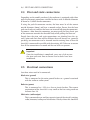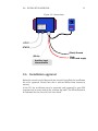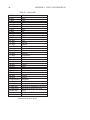
1
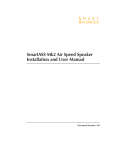
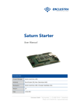
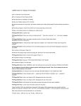
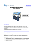
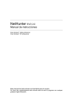
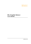
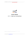
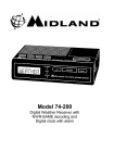
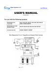
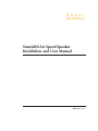
S M A R T
AV I O N I C S
SmartASS Air Speed Speaker
Installation and User Manual
$Revision: 1.3 $
Copyright 2005-2006 Smart Avionics Limited.
All rights reserved.
Smart Avionics Limited reserves the right to change or improve its products
at any time without obligation to upgrade or modify existing products.
Unless indicated otherwise, the contents of this document apply to any
revision of the product’s software.
Document Revision History
Revision
1.3
1.2
1.1
Date
January 2006
October 2005
September 2005
Author
MB
MB
MB
Remarks
Improved diagrams
Various additions in installation section
Initial version
Contents
1 Introduction
1
1.1 Why speak speed? . . . . . . . . . . . . . . . . . . . . . . .
1
1.2 Overview of installation . . . . . . . . . . . . . . . . . . . .
2
1.3 Specifications . . . . . . . . . . . . . . . . . . . . . . . . . .
4
2 Installing the SmartASS
7
2.1 Setting the configuration jumpers . . . . . . . . . . . . . . .
7
2.2 Mounting the enclosure . . . . . . . . . . . . . . . . . . . .
9
2.3 Mounting the control panel . . . . . . . . . . . . . . . . . .
9
2.4 Pitot and static connections . . . . . . . . . . . . . . . . . .
11
2.5 Electrical connections . . . . . . . . . . . . . . . . . . . . .
11
2.6 Installation approval . . . . . . . . . . . . . . . . . . . . . .
13
3 Using the SmartASS
15
3.1 The operating modes . . . . . . . . . . . . . . . . . . . . . .
15
3.2 The controls . . . . . . . . . . . . . . . . . . . . . . . . . . .
16
3.3 Zeroing the SmartASS . . . . . . . . . . . . . . . . . . . . . .
18
A Voice Customisation
19
A.1 The sound files . . . . . . . . . . . . . . . . . . . . . . . . .
19
A.2 Copying the files the MMC card . . . . . . . . . . . . . . . .
21
i
List of Figures
1.1 Enclosure . . . . . . . . . . . . . . . . . . . . . . . . . . . .
3
1.2 Control Panel . . . . . . . . . . . . . . . . . . . . . . . . . .
3
2.1 Configuration Jumpers . . . . . . . . . . . . . . . . . . . . .
8
2.2 Connections . . . . . . . . . . . . . . . . . . . . . . . . . . .
13
iii
List of Tables
1.1 Specifications . . . . . . . . . . . . . . . . . . . . . . . . . .
4
1.2 D-type connector wiring . . . . . . . . . . . . . . . . . . . .
5
A.1 Sound files . . . . . . . . . . . . . . . . . . . . . . . . . . .
20
v
Chapter 1
Introduction
This manual describes how to install and use the Smart Avionics Air Speed
Speaker (hereafter referred to as the ‘SmartASS’).
Please read all of this manual before installing and using the
SmartASS. If you have any questions, please send email to
[email protected].
1.1
Why speak speed?
The SmartASS has been developed to provide the pilot of a homebuilt/experimental aircraft with a means of accurately determining their
airspeed without having to look at the airspeed indicator. It does this
by ‘speaking the speed’ in either knots, MPH or KPH through the intercom/radio system and hence into the pilot’s headset.
It can be used during any phase of flight but it has been specifically developed for use during the approach phase when both airspeed and flight path
need to be accurately controlled.
During the approach to a short field or if the conditions are challenging,
both speed and flight path are critical. The SmartASS is helpful because:
1. It reduces the amount of time the pilot has to be looking inside the
cockpit so more attention can be paid to getting the flight path right.
2. It supplies the pilot with airspeed information in a form that is easier to
assimilate than by looking at an ASI.
1
CHAPTER 1. INTRODUCTION
2
3. It warns the pilot when the speed has deviated significantly from a
nominated ‘target speed’.
This last capability (referred to as ‘speed director’ mode) really sets the
SmartASS apart from a conventional ASI. In speed director mode, instead
of simply reporting the current airspeed, the SmartASS will actively monitor
the airspeed, compare it to the target airspeed and then report deviations
from the target speed. The more the airspeed deviates from the target speed,
the more the SmartASS will talk.
Using the SmartASS, once the aircraft has been configured for final approach and the checks have been carried out, the pilot can concentrate on
eyeballing the approach without having to visually check the airspeed every
few seconds.
!
Important
Although the SmartASS is accurate and reliable it must not be
the only means of determining airspeed installed in the aircraft. A conventional mechanical ASI must also be installed.
1.2
Overview of installation
Chapter 2 (Installing the SmartASS) covers the installation of the SmartASS
in detail, here we just give an overview.
The SmartASS electronics are contained in a lightweight aluminium enclosure (Figure 1.1 on the facing page) that may be mounted in any convenient
position within the instrument panel. The enclosure is equiped with two air
connectors for plumbing the unit into the aircraft’s pitot and static lines.
The SmartASS’s electrical connections are via a D-type connector. A wiring
harness is provided that connects to a small control panel (Figure 1.2 on
the next page) on to which is mounted a combined volume control + on/off
switch and a push button that selects the mode of operation (talking ASI or
speed director). This panel should be mounted in any suitable location such
that it can be easily accessed while flying. The wiring harness also provides
the connections to the aircraft’s power supply and the audio system that
will deliver the audio to the pilot’s headset.
1.2. OVERVIEW OF INSTALLATION
Figure 1.1: Enclosure
Figure 1.2: Control Panel
3
CHAPTER 1. INTRODUCTION
4
1.3
Specifications
All temperature specifications refer to the temperature of the SmartASS
enclosure, not the outside air temperature.
Table 1.1: Specifications
Operating
Temperature
Range
Minimum Speed
-40◦ C - 85◦ C
Maximum
Speed
Absolute
Accuracy
(linearity &
offset)
Repeatability
(pressure
hysteresis)
Supply Voltage
250 Knots / 287 MPH / 462 KPH
Supply Current
Audio Output
Voltage
Minimum Load
Impedance
Electrical
Connector
Air Connectors
30 mA (50 mA when speaking)
1 Volt Peak
Enclosure
Dimensions
Weight
150 x 120 x 40 mm
25 Knots / 30 MPH / 50 KPH
±2%
±0.1%
6-18V
Silent below this
speed
Not an absolute limit
In the temperature
range 0◦ C - 85◦ C.
Assumes unit has
been recently zeroed
At 25◦ C. For speeds
between 25 and 250
Knots
Reverse polarity
protected
With 200 Ohm load
50 Ohms
9W Female D-Type
6 mm OD push-fit
310 grams
1/8 BSP fittings
available on request
Includes mounting
tabs and connectors
Enclosure 230,
panel/harness 80
The SmartASS is supplied with a pre-wired D-type connector so you should
not need to wire your own. In case you do want to wire your own connector,
Table 1.2 on the facing page lists the connections.
1.3. SPECIFICATIONS
Table 1.2: D-type connector wiring
1
2
3
4
5
6
7
8
9
Ground
Audio out
Volume A
RS485 A
+12V Supply
Ground
Mode Switch
Volume B
RS485 B
Connect to radio/intercom ground
To radio/intercom audio input
Connect 10K log pot between Volume A & B
Do not connect
A small fuse is needed to protect the wiring
Internally connected to pin 1
Connect normally open switch to ground
Connect 10K log pot between Volume A & B
Do not connect
5
6
CHAPTER 1. INTRODUCTION
Chapter 2
Installing the SmartASS
Installation of the SmartASS consists of the following steps:
1. Setting the configuration jumpers (if necessary).
2. Mounting the enclosure within the instrument panel.
3. Mounting the control panel on the instrument panel.
4. Connecting the pitot and static connections.
5. Connecting the power supply and audio output wires.
2.1
Setting the configuration jumpers
The default behaviour of the SmartASS can be modified by installing configuration jumpers1 (supplied) on the circuit board. To gain access to the
board remove the four M4 screws and the top cover.
Figure 2.1 on the next page shows the layout of the jumpers. J1 (speed
units selection) is near the back edge of the PCB.
1
A jumper is a small link that connects two Printed Circuit Board pins together. The
jumpers supplied with the SmartASS have a red plastic insulating outer.
7
CHAPTER 2. INSTALLING THE SMARTASS
8
Figure 2.1: Configuration Jumpers
Add jumper to report
speed in KPH or MPH
Do not remove
this jumper!
KPH MPH
J1
PL1
BA
Remove this jumper to
double reporting period
J2
Configuring the speed units
By default, the SmartASS reports the airspeed in Knots. If desired,
the airspeed can be reported in either MPH or KPH by installing the
appropriate jumper as follows: at the very back of the circuit board
(away from the connectors) you will find 3 pins labeled J1 and also
KPH and MPH. Install a jumper between either the first and second pin
or between the second and third pins depending on whether you want
the airspeed units to be KPH or MPH.
Configuring the repeat period
As supplied, the SmartASS waits 2.5 seconds between speaking each
speed in talking ASI mode. By removing the jumper that is installed
in J2 position A (the right hand pair of pins), the repeat period can
be doubled to 5 seconds.
!
Important
The circuit board contains components that may be damaged
by static electricity. Try to avoid touching the components
on the board and, if possible, remove any static charge that
you may be carrying by touching something that is earthed
before handling the unit.
Make sure you do not remove the existing jumper that is
positioned on the left hand side of a row of 8 pins towards
the back of the circuit board. That jumper is required at all
times.
After the jumpers have been configured, replace the cover and screws.
2.2. MOUNTING THE ENCLOSURE
2.2
9
Mounting the enclosure
The enclosure can be mounted in any convenient position within the instrument panel area. Four M5 mounting holes are provided. Remember to
leave adequate space for the D-type conector and the wiring harness (a
minimum of 65 mm should be allowed). The length of the wires between
the enclosure and the control panel is 1 metre.
The enclosure can be mounted in any orientation. Although the SmartASS is
robust, avoid subjecting it to excessive vibration or extremes of temperature.
2.3
Mounting the control panel
The control panel holds the combined on/off switch + volume control
and the mode button. It should be mounted in a position such that the
mode button can easily be operated while flying. How exactly this panel is
mounted depends on the thickness of the surrounding instrument panel.
If the instrument panel is no more than 4mm thick, the SmartASS control
panel can simply be mounted by drilling two holes (one for the potentiometer and the other for the push switch) and then mounting those controls
through the instrument panel. The SmartASS control panel will be held in
place by the nuts that fasten the controls to the instrument panel.
The hole required for the potentiometer is 9.5mm diameter and the hole for
the mode switch is 6.5mm diameter. The distance between the hole centres
is 23mm.
If the instrument panel is more than 4mm thick, several alternatives are
possible:
1. Mount the SmartASS control panel on a sub-panel which is not more
than 4mm thick (as described above) and then mount the sub-panel
somewhere.
2. If it is possible to locally reduce the thickness of the instrument panel
to 4mm or less by removing material behind where the SmartASS panel
is to be located, then that would allow the controls to be mounted as
described above.
3. The instrument panel could be cut away sufficiently to allow the bodies
of the controls to pass through it. The control panel can then either be
10
CHAPTER 2. INSTALLING THE SMARTASS
bonded to the front of the instrument panel or it could be drilled near
the corners to accept small screws to hold it to the instrument panel.
The controls would then be attached to the SmartASS panel using their
fixing nuts.
4. The SmartASS control panel could be discarded altogether and the controls mounted in some other way of your own devising.
However the controls are mounted, take care to ensure that the wires are not
subject to excessive strain and that they cannot vibrate enough to fracture
the terminals. If the cables are too long, coil them up and secure with cable
ties.
2.4. PITOT AND STATIC CONNECTIONS
2.4
11
Pitot and static connections
Depending on the model purchased, the enclosure is equipped with either
push-fit pneumatic connectors suitable for hose with an outside diameter
of 6 mm or 1/8 BSP female connectors.
If using the push-fit connector version, the hose must be of the correct
outside diameter (6mm) and have a smooth surface. Ensure that the hose
ends are cleanly cut and that the hoses are inserted fully into the connectors.
To remove a hose from the connector, you must push the blue plastic part
of the connector towards the threaded body while pulling the hose out.
Exactly how the pitot and static connections are plumbed into the aircraft’s pitot and static lines will be different for each aircraft but, generally
speaking, tee connectors can be inserted into the existing lines so that the
SmartASS is connected in parallel with the existing ASI. Take care to ensure
that all the connections are sound and that no leaks are present.
!
Important
Once the installation is completed, carry out a leak test on
the pitot and static lines to ensure that no leaks have been
introduced.
2.5
Electrical connections
Just three wires need to be connected:
Black wire (ground)
This is connected to the main ground busbar or a ground associated
with the radio or audio system.
Red wire (power)
This is connected to +12V via a fuse or circuit breaker. The current
requirement of the SmartASS is very small so the fuse rating need not
be more than 1A.
White wire (audio output)
This is connected to an auxiliary or music input of the aircraft’s existing
radio/intercom/audio panel installation. Exactly where this should be
12
CHAPTER 2. INSTALLING THE SMARTASS
connected obviously depends on the specific equipment being connected to.
Development of the SmartASS was carried out in conjunction with a
Flightcom 403mc intercom unit and the output was simply connected
to the ‘Aux input’ of that unit.
In most installations, the audio output wire probably doesn’t need to
be shielded unless it is very long or it runs near to a source of electrical
noise. If you wish to shield the wire, the easiest way of doing that is
to remove the braded shield intact from a piece of shielded cable and
slip that over the audio output wire, connecting one end of the shield
to ground. Heatshrink sleeving can be used to stop the ends of the
shield from fraying
All three wires should be trimmed to length rather than coiled up if they
are too long.
Ensure that the screws that fasten the D-type connector to the SmartASS are
reasonably tight so that the connector will not come adrift.
Figure 2.2 on the facing page shows the connections to the SmartASS enclosure.
Note
Intercoms and radios often have the ability to mute the auxiliary
input when radio transmissions are being received. It is up to you
to decide whether to mute the output from the SmartASS or not.
During development, it was found that muting the SmartASS when
radio messages were received was distracting because its spoken
messages were broken up. It was better to not mute the SmartASS
but, instead, to keep its volume fairly quiet so you can still easily
hear radio transmissions.
If you wish to add a switch to mute the output, you could simply
wire the switch into the white wire to disconnect the audio output.
Note
If the volume of the SmartASS’s output is not well matched to the
sensitivity of the existing equipment’s input and that equipment has
no means of adjusting its sensitivity, please contact Smart Avionics
for advice.
2.6. INSTALLATION APPROVAL
13
Figure 2.2: Connections
ON / OFF
Smart Avionics SmartASS
Serial No:
Date:
PITOT
STATIC
SmartASS
MODE
PITOT
STATIC
(Black) Ground
(White)
Auxiliary Input
Intercom/radio
2.6
(Red)
+12V fused supply
Installation approval
Before the aircraft can be flown with the SmartASS installed, the installation
has to be approved. Exactly how this is achieved differs from country to
country.
In the UK, the installation must be inspected and approved by your PFA
inspector and an entry made in the airframe log book. The PFA will need to
be informed that the SmartASS has been fitted.
14
CHAPTER 2. INSTALLING THE SMARTASS
Chapter 3
Using the SmartASS
3.1
The operating modes
The SmartASS has two modes of operation:
Talking ASI Mode
This mode simply speaks the current airspeed every few seconds. The
repeat period can be either 2.5 or 5 seconds (selectable at installation
time). Also, if the speed changes very rapidly, the new speed is spoken
straight away.
When the speed is less than 25 Knots (30 MPH, 50 KPH) the voice is
muted. When the SmartASS is turned on, it always starts in talking ASI
mode.
Speed Director Mode
In this mode, the airspeed is continuously measured and compared to
a target speed. The SmartASS reports as follows:
• If the speed is within 5% of the target speed, it says ‘Speed Good’
every 8 seconds
• If the speed is between 5% and 10% too fast, it says ‘Fast’ every
4 seconds.
• If the speed is between 5% and 10% too slow, it says ‘Slow’ every
4 seconds.
• If the speed is between 10% and 15% too fast, it says ‘Very Fast’
every 2 seconds.
15
CHAPTER 3. USING THE SMARTASS
16
• If the speed is between 10% and 15% too slow, it says ‘Very Slow’
every 2 seconds.
• If the speed is more than 15% too slow or too fast, the appropriate
message is prefixed with a chime.
If the speed drops to below 25% of the target speed, the SmartASS
switches to talking ASI mode.
•
•
•
•
3.2
Note
When using speed director mode, try not to ‘chase’ the
airspeed.
Unless the airspeed is wildly wrong, don’t make large adjustments to the airspeed.
Aim to smoothly increase or decrease the speed to keep the
‘speed good’.
Remember that the airspeed cannot change instantly, it
takes a few moments for a change in attitude or power to
have an effect on the airspeed and a bit longer for the SmartASS (and your mechanical ASI) to measure that speed.
The controls
The SmartASS has been designed to be very easy to use. Just two controls
are provided:
1. Volume control + on/off switch
2. Mode button
The combined on/off switch and volume control works in the conventional
manner: turning the volume control clockwise increases the volume of the
speech. Turning the volume control anti-clockwise reduces the volume and
when turned fully anti-clockwise, switches off the power to the SmartASS.
When the SmartASS is switched on, it says ‘Airspeed in Knots1 ’ and then if
the unit auto-zeros itself it will say ‘Zeroed’. Section 3.3 on page 18 has
more information about zeroing.
1
Or MPH or KPH depending on the units selected during installation.
3.2. THE CONTROLS
!
17
Important
If when the SmartASS is switched on the airspeed is at least 25
Knots (30 MPH, 50 KPH), the voice will say ‘Compare to ASI’
after the speed is first reported. This is to remind the pilot
to check that the spoken speed is consistent with the speed
indicated on the ASI. If the speeds tally, the SmartASS can
be considered trustworthy. If there is a significant difference
between the spoken speed and the speed shown on the ASI,
the SmartASS should not be used until the discrepancy has
been investigated.
The mode button has two primary functions:
Selecting the operating mode
Pressing the mode button briefly toggles the mode of operation between talking ASI mode and speed director mode. The mode change
is announced as follows: when talking ASI mode is selected, the SmartASS says ‘Airspeed’. When speed director mode is selected, the SmartASS announces the (previously captured) target airspeed by saying
‘Target speed is ...’. Listen to the number it says and confirm that is the
speed you want. If the number it says is not what you want, you will
need to capture a new airspeed as described next. Until an airspeed
has been captured, the SmartASS will not select speed director mode.
Capturing the target airspeed
Pressing the mode button for more than 1/2 second ‘captures’ the
current airspeed and switches to speed director mode if that mode
is not already active. The new target airspeed will be announced as
‘Target speed is ...’ and will be stored until another speed is captured.
The target airspeed is remembered even when the power is off.
CHAPTER 3. USING THE SMARTASS
18
3.3
Zeroing the SmartASS
To ensure the airspeed reported by the SmartASS is as accurate as possible,
the unit requires zeroing occasionally. This will remove any offset error
introduced as the pressure sensor and the electronic components age.2
Whenever the SmartASS is turned on, as long as the current differential
pressure is small, it will be zeroed automatically to remove the offset error.
If the differential pressure is not small when the unit is turned on, this
auto-zeroing will not occur.
It is possible to manually zero the SmartASS at any time by turning the unit
on while pressing the mode button. When the voice says ‘Zeroed’, take your
finger off the mode button.
!
Important
To ensure that the reported speed is accurate, do not manually zero the SmartASS if any of the following are true:
• The aircraft is moving at more than walking pace.
• The wind is blowing into the pitot and it is more than
a very gentle breeze.
• The pitot cover is in position.
It is expected that in normal use, auto-zeroing will occur from time to time
and so it should not normally be necessary to manually zero the SmartASS
unless you believe the reported airspeed is incorrect.
2
Due to the fact that airspeed is proportional to the square root of the dynamic pressure,
the effect of a small offset error in the pressure measurement is only really significant at
very low airspeeds. It’s still worth removing the error to get the best possible result.
Appendix A
Voice Customisation
The SmartASS voice can be customised by providing a new set of sound files.
The new sound files are stored on a Multi Media Card (MMC) which is then
inserted into a socket on the SmartASS PCB. This Appendix describes the
sound files required and the generic procedure for installing them.
MMC cards are made by many manufacturers and come in different capacities. It is not guaranteed that the SmartASS will work with all known MMC
cards. Development was carried out using a SanDisk 128MB card. As less
than 1 MB of storage is required for the sound files, smaller capacity MMC
cards can be used.
The original voice is not affected by the customisation process. It is simply
ignored while the MMC card is present. Removing the MMC card from the
SmartASS will allow the original voice to be used again.
A.1
The sound files
The voice messages played by the SmartASS are stored as a set of MP3 files.
Each file contains a word or a complete phrase. To customise the SmartASS
voice, each of the files listed in Table A.1 on the following page must be
created containing the appropriate message.
The MP3 files should be mono, sampled at 44.1 kHz and have a bitrate
of 64 K bits/second. How the audio clips are recorded and converted into
MP3 files is beyond the scope of this manual but it can be done on a home
computer equipped with a sound card and microphone.
19
APPENDIX A. VOICE CUSTOMISATION
20
Table A.1: Sound files
File Name
0.mp3
1.mp3
2.mp3
3.mp3
4.mp3
5.mp3
6.mp3
7.mp3
8.mp3
9.mp3
10.mp3
11.mp3
12.mp3
13.mp3
14.mp3
15.mp3
16.mp3
17.mp3
18.mp3
19.mp3
20.mp3
30.mp3
40.mp3
50.mp3
60.mp3
70.mp3
80.mp3
90.mp3
airspeed.mp3
and.mp3
asik.mp3
asikph.mp3
asimph.mp3
chime.mp3
cmptoasi.mp3
fast.mp3
Content
Zero
One
Two
Three
Four
Five
Six
Seven
Eight
Nine
Ten
Eleven
Twelve
Thirteen
Fourteen
Fifteen
Sixteen
Seventeen
Eighteen
Nineteen
Twenty
Thirty
Forty
Fifty
Sixty
Seventy
Eighty
Ninety
Airspeed
And
Airspeed in knots
Airspeed in kilometers per hour
Airspeed in miles per hour
Ding!
Compare to ASI
Fast
(continued on next page)
A.2. COPYING THE FILES THE MMC CARD
21
Table A.1: Sound files (cont.)
File Name
good.mp3
hundred.mp3
slow.mp3
speed.mp3
tsi.mp3
veryfast.mp3
veryslow.mp3
zeroed.mp3
A.2
Content
Good
Hundred
Slow
Speed
Target speed is
Very fast
Very slow
Zeroed
Copying the files the MMC card
Once the required audio files have been created, they must be copied to a
MMC card using the following generic instructions:
1. Reformat the MMC card so that it is completely empty. The card must be
formatted such that it contains a FAT16 filesystem (probably the default
on most systems).
2. Copy the audio files to the MMC card.
3. Insert the MMC card into the socket on the SmartASS PCB. The socket is
located on the right hand side of the PCB under the flexible cable.
!
Important
It is particularly important that the MMC card is reformatted
before any files are copied to it. If you wish to replace a single
file on the card, you must still reformat the card and copy
all the files again. If you do not do this, the sound files may
be partially or wholely unreadable.
Index
A
airspeed
capturing, 17
button, 17
modes of operation, 15
MP3 file, 19
MPH, 8
mute
audio input, 12
switch, 12
C
capturing airspeed, 17
configuring
repeat period, 8
speed units, 8
connections
electical, 11
pitot and static, 11
control panel
mounting, 9
O
on/off switch, 16
operating modes, 15
P
pitot connnection, 11
E
electrical connections, 11
enclosure
mounting, 9
S
specifications, 4
speed director mode, 2, 15
static connection, 11
I
installation
approval, 13
T
talking ASI mode, 15
V
voice
customise, 19
volume control, 16
J
jumper
configuration, 7
Z
zeroing, 18
K
Knots, 8
KPH, 8
M
MMC card, 19
mode
23