1
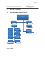
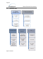
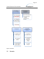
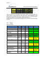
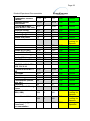
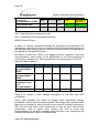
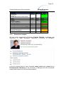
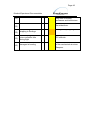
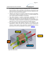
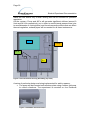
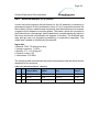
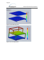
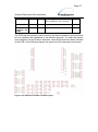
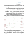
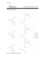
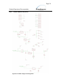
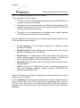
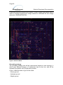
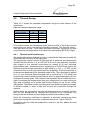
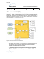
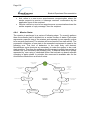
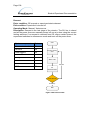
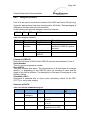
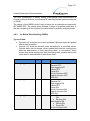
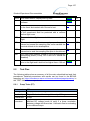
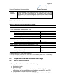
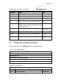
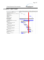
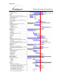
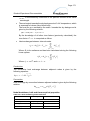
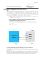
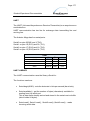
Page 92 Student Experiment Documentation 4.7 Power System The system is divided into three different power lines: PL1 provides pump and pinch valves which have the highest power consumption; PL2 feeds heaters and OPC; PL3 feeds all the other instruments and the electronics. The power is provided by two different sources: BEXUS batteries that provide power to PL2 and PL3. In particular two batteries will be put in parallel through the power board. A5 battery pack, which provides power to PL1 and is designed to match the high power request for this line. We estimated the power budget for each one of the lines separately and consequently chose the best solution for the batteries taking into account performance, costs, and reliability. 4.7.1 Power Line One overview (PL1) The power budget for this line was estimated considering the following assumption that represent a worst-case scenario: The pump is turned on at ground and kept at 6V for pre-launch and climbing phase (for a total of 3 hours) and at 12 V (maximum) for the sampling phase. PL1 is then turned off before the descending phase. 12 V is in fact the voltage required to obtain the maximum airflow of 32 l/min, which is much higher than the target flow of 9 l/min that we have to achieve during sampling phase. Vacuum chamber tests will determine what is the real voltage required to obtain this value in a low-pressure environment, and therefore allow a better estimation of the power consumption. Table 4.7-1 Power line one (PL1) Component N° Hours Current Voltage Power Total A Total W Total Wh Pump 1 6 3A 6V (12V for 3 h) 18÷36 W 3A 18÷36 W 162 Wh