1
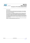
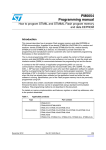
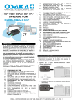
16-bit advanced control timer (TIM1)
RM0031
•
Configure the 3 timer inputs XORed to the TI1 input channel by writing the TI1S bit to 1
in the TIMx_CR2 register,
•
Program the time base: write the TIMx_ARR to the max value (the counter must be
cleared by the TI1 change). Set the prescaler to get a maximum counter period longer
than the time between 2 changes on the sensors,
•
Program the channel 1 in capture mode (TRC selected): write the CC1S bits in the
TIMx_CCMR1 register to ‘11’. You can also program the digital filter if needed,
•
Program the channel 2 in PWM 2 mode with the desired delay: write the OC2M bits to
‘111’ and the CC2S bits to ‘00’ in the TIMx_CCMR2 register,
•
Select OC2REF as trigger output on TRGO: write the MMS bits in the TIMx_CR2
register to ‘101’.
In the TIM1 advanced-control timer, the right ITR input must be selected as trigger input, the
timer is programmed to generate PWM signals, the capture/compare control signals are
preloaded (CCPC=1 in the TIMx_CR2 register) and the COM event is controlled by the
trigger input (COMS=1 in the TIMx_CR2 register). The PWM control bits (CCxE, OCxM) are
written after a COM event for the next step.
Figure 118. Example of Hall sensor interface
4)(
4)(
)NTERFACINGTIMER
4)(
COUNTER#.4
##2
##2
#!
#!
#
#!
#!"
#
42'//#2%&
ADVANCEDCONTROLTIMERS4)-
#/-
/#
/#.
/#
/#.
/#
/#.
7RITE##X%##X.%
AND/#X-FORNEXTSTEP
340/595
AI
DocID15226 Rev 11