1
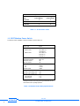
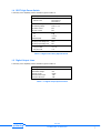
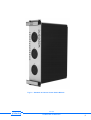
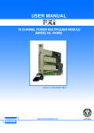
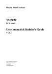
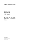
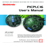
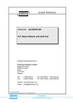
USER MANUAL
pickering
Model No. 20-150
Power Relay Module
Designed & Manufactured by:Pickering Interfaces Limited.
Stephenson Road
Clacton-on-Sea
Essex
CO15 4NL
England
Tel:
Fax:
+44 1255-687900
+44 1255-425349
Internet: www.pickeringtest.com
E Mail: [email protected]
Issue 6.00 Aug 2008
© Copyright (2008) Pickering Interfaces Ltd. All Rights Reserved
pickering
20-150
POWER RELAY MODULE
1
HELP!!!
If you need assistance with your Pickering Interfaces Switching
System: Switching problems, Programming or Integration within your Test
System. – Please ring Pickering Interfaces and ask for “Technical
Support”.
Alternatively you may fax, email or connect to our Internet Web Site.
A full set of operating manuals, application notes and software drivers is
available on CD ROM.
pickering
2
20-150
POWER RELAY MODULE
Contents
Section 1
Power Relay Module.................................................................................................. 5
Section 2
Self Test .................................................................................................................... 11
Section 3
Programming ........................................................................................................... 13
Section 4
Connector Pin-Out Diagrams................................................................................... 15
Section 5
Front Panel Layout .................................................................................................. 19
Section 6
Reconfiguring Driver Card to Your Application......................................................... 21
Section 7
PCB Details / Circuit Diagrams ................................................................................ 25
pickering
20-150
POWER RELAY MODULE
3
pickering
4
20-150
POWER RELAY MODULE
Section 1
Power Relay Module
1.1 Features
• Up To 16 Power Relays Per Module
• Choice of 13A or 30A Power Relays
• Switch Up To 250V a.c.
• Front Panel LED Indicators For Each Relay
• 8 Additional Control Lines For Operating External Relays
1.2 Description
The 20-150 range of Power Switching Modules are available with a choice of medium power 13A relays or heavy duty
30A relays.
The standard version (module type 20-150-001) has 16 SPDT Power Relays which will switch up to 13A at 30V d.c. or
250V a.c. and are suitable for switching highly inductive/capacitive loads. The relay is socket mounted with the switch
contact taken directly from the socket (no vulnerable PCB tracks).
Further versions are available which have combinations of 13A and 30A Power Relays for applications requiring greater
current capability.
20-150-001
16 x SPDT Medium Power Relays, 13 A.
20-150-201
8 x SPDT Medium Power Relays, 13A and 4 x SPST High Power Relays, 30A
20-150-101
20-150-301
12 x SPDT Medium Power Relays, 13A and 2 x SPST High Power Relays, 30A.
2 x SPDT Medium Power Relays, 13A and 8 x SPST High Power Relays, 30A
1.2.1 Connectors
Connections to the 20-150 series modules are made via front panel mounted AMP CPC connectors. See Section 4 for
connection details.
1.2.2 Built-in Self Test
Self Test is always performed at power up and may also be exercised either by using the modules individual RS-232
interface or under program control. Any service or error indications can be diagnosed using the DIAGNOSTIC? command,
refer to Section 2 for further details.
1.2.3 Front Panel
A typical front panel is comprised of four elements, please refer to Fig 1.2.
Status Display, 5 LED Indicators:-
Power LED. Connected to system power supply.
Active LED. On whenever one or more relays are selected. Use the VIEW? command for a list of all active channels.
Self-Test LED. Active while the self-test is in progress.
Warning LED. Indicates that the self test has detected a relay parameter drifting towards out of range.
Error LED. Indicates that an error was found during self-test.
Internal RS-232 Connector. Allows the module to be connected to a terminal or PC via the serial cable provided to
enable configuration details to be set up by the user.
Switch Contact Connectors, AMP CPC connectors.
Relay Status Indicators, Each relay has its individual LED status indicator which is on when the relay is energised.
1.2.4 Width and Dimensions
The Power Relay Module conforms to the 6U height (262mm) Eurocard standard and is housed in a 160mm deep
screened plug-in module. Panel width is 15HP (3.0 inches, 76.2mm).
This is a double height module and must be mounted into a double height (6U) case.
pickering
20-150
POWER RELAY MODULE
5
20-110 Power Relays
Product
No. of Medium
Code
Power Relays
20-150-001
16
20-150-101
No. of High
Power Relays
12
20-150-201
20-150-301
0
2
8
2
4
8
Table 1.1 20-150 Order codes
1.3 SPDT Medium Power Switch
A summary of the capability of these modules is given in table 1.2.
Contact Type
AgCdO
Contact Current Rating
Resistive Load
13A at 250V a.c.
13A at 30V d.c.
13A at 250V a.c.
5A at 30V d.c.
5A at 30V d.c.
Inductive Load
Max Standoff Voltage
Max Switching Voltage
Max Switch Current
Max Carry Current
Contact Resistance
On:
Off:
Bandwidth (50Ω)
600V d.c.
250V r.m.s.
13A
13A
Max Operate Time†
Max Relay Close Settling Time
Max Relay Open Settling Time
Expected Life (Operations)
Low power load
Full power load
1 5 0 mΩ
> 108 Ω
10MHz
15ms
10ms
7ms
> 107
> 105
† This is the time taken from the start of the IEEE-488 or RS-232
message to the closure of the relay (assuming fast IEEE-488 / RS-232
communication and no pending operations.
Table 1.2 Medium Power Relay Specifications
6
pickering
20-150
POWER RELAY MODULE
1.4 SPST High Power Switch
A summary of the capability of these modules is given in table 1.3.
Contact Type
Silver Alloy
Contact Current Rating
Resistive Load
30A at 250V a.c.
30A at 30V d.c.
Max Standoff Voltage
Max Switching Voltage
Max Switch Current
Max Carry Current
Contact Resistance
On:
Off:
Bandwidth (50Ω)
600V d.c.
270V a.c. r.m.s.
30A
30A
Max Operate Time†
Max Relay Close Settling Time
Max Relay Open Settling Time
Expected Life (Operations)
Low power load
Full power load
5m Ω
> 10 8 Ω
10MHz
30ms
20ms
5ms
> 5 x 10⁶
> 105
Table 1.3 High Power Relay Specifications
1.5 Digital Output Lines
A summary of the capability of these modules is given in table 1.4.
Device Type
Output Type
Max Standoff Voltage
Max Sink Current
Max Power Each Output
Max Power All Outputs
ULN2803
Open Collector Driver
50V
500mA
1.0W
1.6W
Table 1.4 Digital Output Specifications
pickering
20-150
POWER RELAY MODULE
7
B1
A1
C1
B1
A1
C1
13A
B2
A2
C2
B2
A2
C2
13A
B3
A3
C3
13A
B3
A3
C3
13A
B16
A16
C16
13A
B2
A2
C2
B3
A3
C3
13A
13A
A9
C9
A10
C10
A11
13A
C11
A14
30A
C14
13A
20-150-101
20-150-001
B1
A1
C1
30A
C13
13A
B12
A12
C12
13A
A13
30A
30A
B1
A1
C1
B2
A2
C2
13A
13A
A3
C3
A4
C4
A5
30A
C5
30A
30A
30A
A12
B8
A8
C8
C12
30A
A10
13A
C10
20-150-201
20-150-301
Fig 1.1 Power Relay Schematics
8
pickering
20-150
POWER RELAY MODULE
30A
Fig 1.2 Standard 20-150-001 Power Switch Module
pickering
20-150
POWER RELAY MODULE
9
pickering
10
20-150
POWER RELAY MODULE
Section 2
Self Test
2.1 Self-Test Function
Self-Test is invoked at power on and may also be operated under software control using the *TST? command. If the SelfTest fails the Error LED on the front panel will be turned on. Any test parameter that is seen from previous test data to
be drifting towards out of specification, but does not at present warrant an error alarm, will turn on the Service LED on the
front panel. A full pass/fail description is available using the DIAGNOSTIC? command.
Self-Test comprises 3 levels, see Fig 2.1:1.
Logic Test: Checks all logic including on-board microprocessor RAM, ROM, and EEPROM, relay drivers etc.
2.
Analogue Test: Checks voltage levels are correct for all the power supplies and front panel LED's.
3.
Relay Coil Test: The resistance of all relay coils are checked.
Note: In the unlikely event of a relay needing replacement additional relays are available from Pickering Interfaces.
2.2 Self-Test Operation
Self Test is always run at power on, taking approximately 5 seconds.
If self test is run under software control it will firstly clear the whole module . So it is very important to prepare your external
instruments and U.U.T. for this! During self-test all switches are opened so your external circuitry will see only very high
resistance inputs.
When the self-test has finished the relays will be returned to an all clear state (i.e. the previous state will not be
remembered!).
Please note that because of the long self-test time your computer may time out waiting for the test result (many PC's have
default timeouts set to 10 seconds).
2.3 Configuring Self Test
Self Test may be configured so that some or all of the test functions can be disabled. This is achieved by setting the
appropriate bit in the test configuration byte. Refer to Section 6 for details on how to reconfigure the driver card to your
application.
2.4 Detailed Self Test Reporting using the DIAGNOSTIC? Query
The DIAGNOSTIC? query will give an ASCII string detailing any self test failures. These will include:Logic:
µP, RAM, EPROM, Relay Drivers, Invalid Link Settings etc.
Analogue:
5 Volt supply low etc.
Relay Coils: Open Circuit Coil.
This string is not intended to be processed by the user’s software, it is suitable for copying directly onto the screen of your
control computer. This information will then indicate maintenance required (please contact Pickering for further help).
pickering
20-150
POWER RELAY MODULE
11
SELF TEST INITIATED BY:
. POWER ON
. *TST? INTERFACE CMND
. TS 1 RS232 COMMAND
CLEAR MODULE
MEMORY and LOGIC
TEST
Yes
LOGIC TEST
FAIL ?
No
ANALOGUE TEST
Yes
ANALOGUE
TEST FAIL ?
No
RELAY COIL TEST
Yes
RELAY COIL
TEST FAIL ?
No
SELF TEST PASS
SELF TEST FAILURE
ERROR LED ON
USE DIAGNOSTIC? COMMAND
Fig 2.1 Self-Test: Basic Flow Diagram
pickering
12
20-150
POWER RELAY MODULE
Section 3
Programming
3.1 Select Module Address
The module internal address is factory pre-set, please refer to case schematic diagram at front of manual. To change the
internal address please refer to section 6, Reconfiguring Driver Card to Your Application.
3.2 Programming Using the Intelligent GPIB/RS-232 Interface
The 20-150 module is simple to program either by single bit, byte (8 bits) or word (16 bits).
ARESET a
Clear all outputs on module a
CLOSE a,b
Set bit number b on module a
DELAY t
Force a minimum delay of t milliseconds between two instructions
OPEN a,b
Clear bit number b on module a
RESET
Clear all bits/switches on all modules
SIZE sThis is used to specify the word size: s = 1 for byte, s = 2 for 16 bit word and s = 3 for 32 bit word (16 bit is usually
the factory default).
VIEW? a[,b] View status of module a, can be viewed at any time either as a word or by bit b as a logical value (1 or 0)
WRITE a,c,w Send word w to module a block position c
The module is programmed as an 8 bit output port using either single bit, byte (8 bits), or 16 bit word:To close relay number 5 on module 11.
CLOSE 11,5
Or to close first 16 relays on module 8.
SIZE 2 (this selects byte length words)
WRITE 8,1,65535
For more details on programming see the programming manual for the IEEE-488.2/RS-232 interface module.
3.3 Operating Speed
Multiplexer operating speed, i.e. the time taken to open or close a channel, is approximately 10mS using the 10-921 IEEE488.2/RS-232 interface module.
pickering
20-150
POWER RELAY MODULE
13
pickering
14
20-150
POWER RELAY MODULE
Section 4
Connector Pin-Out Diagrams
Connector A
Front Panel Description
Pin No.
1
Digital Com.
2
Digital Gnd.
3
Digital O/p 1
4
Digital O/p 2
5
Digital O/p 3
6
Digital O/p 4
7
Digital O/p 5
8
Digital O/p 6
9
Digital O/p 7
10
Digital O/p 8
11
not used
12
not used
13
not used
14
not used
15
not used
16
RL1 no
17
RL1 com
18
RL1 nc
19
RL2 no
20
RL2 com
21
RL2 nc
22
RL3 no
23
RL3 com
24
RL3 nc
Connector B
Front Panel
Pin No.
1
2
3
4
5
6
7
8
9
10
11
12
13
14
15
16
17
18
19
20
21
22
23
24
Description
RL4 no
RL4 com
RL4 nc
RL5 no
RL5 com
RL5 nc
RL6 no
RL6 com
RL6 nc
RL7 no
RL7 com
RL7 nc
RL8 no
RL8 com
RL8 nc
RL9 no
RL9 com
RL9 nc
RL10 no
RL10 com
RL10 nc
RL11 no
RL11 com
RL11 nc
Connector C
Front Panel
Pin No.
1
2
3
4
5
6
7
8
9
10
11
12
13
14
15
16
17
18
19
20
21
22
23
24
Description
RL12 no
RL12 com
RL12 nc
RL13 no
RL13 com
RL13 nc
RL14no
RL14 com
RL14 nc
RL15 no
RL15 com
RL15 nc
RL16 no
RL16 com
RL16 nc
not used
not used
not used
not used
not used
not used
not used
not used
not used
Fig 4.1 20-150-001 CPC Connector Pin Out Diagram.
pickering
20-150
POWER RELAY MODULE
15
Connector A
Front Panel Description
Pin No.
1
not used
2
Digital Com.
3
Digital Gnd.
4
Digital O/p 1
5
Digital O/p 2
6
Digital O/p 3
7
Digital O/p 4
8
Digital O/p 5
9
Digital O/p 6
10
Digital O/p 7
11
Digital O/p 8
12
not used
13
RL1 no
14
RL1 com
15
RL1 nc
16
RL2 no
17
RL2 com
18
RL2 nc
19
RL3 no
20
RL3 com
21
RL3 nc
22
not used
Connector B
Front Panel
Pin No.
1
2
3
4
5
6
7
8
9
10
11
12
13
14
15
16
17
18
19
20
21
22
Description
RL13 no
RL4 no
RL4 com
RL4 nc
RL5 no
RL5 com
RL5 nc
RL6 no
RL6 com
RL6 nc
RL7 no
RL7 com
RL7 nc
RL8 no
RL8 com
RL8 nc
RL9 no
RL9 com
RL9 nc
not used
not used
RL13 com
Connector C
Front Panel
Pin No.
1
2
3
4
5
6
7
8
9
10
11
12
13
14
15
16
17
18
19
20
21
22
Description
RL14 no
RL10 no
RL10 com
RL10 nc
RL11 no
RL11 com
RL11 nc
RL12no
RL12 com
RL12 nc
not used
not used
not used
not used
not used
not used
not used
not used
not used
not used
not used
RL14 com
Fig 4.2 20-150-101 CPC Connector Pin Out Diagram.
Connector A
Front Panel Description
Pin No.
1
RL3 com
2
Digital Com.
3
Digital Gnd.
4
Digital O/p 1
5
Digital O/p 2
6
Digital O/p 3
7
Digital O/p 4
8
not used
9
Digital O/p 5
10
Digital O/p 6
11
Digital O/p 7
12
Digital O/p 8
13
not used
14
not used
15
RL1 no
16
RL1 nc
17
not used
18
RL2 no
19
RL2 nc
20
RL1 com
21
RL2 com
22
RL3 no
pickering
16
Connector B
Front Panel
Pin No.
1
2
3
4
5
6
7
Description
RL4 com
RL4 no
RL5 com
RL5 no
RL10 com
RL6 com
RL6 no
Connector C
Front Panel
Pin No.
1
2
3
4
5
6
7
Description
RL7 com
RL7 no
RL8 com
RL8 no
RL10 no
RL9 com
RL9 no
Fig 4.3 20-150-301 CPC Connector Pin Out Diagram.
20-150
POWER RELAY MODULE
Connector A
Front Panel
Pin No.
1
2
3
4
5
6
7
8
9
10
11
12
13
14
15
16
Connector B
Description
Not used
Digital Com.
Digital Gnd.
Digital O/p 1
Digital O/p 2
Digital O/p 3
Not used
Digital O/p 4
Digital O/p 5
Not used
Digital O/p 6
Digital O/p 7
Digital O/p 8
Not used
Not used
Not used
Connector C
Front Panel
Pin No.
Description
Front Panel
Pin No.
1
2
3
4
5
6
7
8
9
10
11
12
13
14
15
16
RL9 com
RL1 no
RL1 com
RL1 nc
RL2 no
RL2 com
RL9 no
RL2 nc
RL3 no
RL10 com
RL3 com
RL3 nc
RL4 no
RL4 com
RL10 nc
RL4 no
1
2
3
4
5
6
7
8
9
10
11
12
13
14
15
16
Description
RL11 com
RL5 no
RL5 com
RL5 nc
RL6 no
RL6 com
RL11 no
RL6 nc
RL7 no
RL12 com
RL7 com
RL7 nc
RL8 no
RL8 com
RL12 nc
RL4 no
Fig 4.4 20-150-201 CPC Connector Pin Out Diagram.
pickering
20-150
POWER RELAY MODULE
17
POW
Connector A
Connector B
Connector C
20-150-001
Power Relay Module
ACT
POW
Connector A
ACT
POW
Connector A
POW
Connector A
ACT
ACT
TEST
TEST
TEST
TEST
ERR
ERR
ERR
ERR
MAN
TEST
MAN
TEST
Connector B
Connector C
3.0"
Connector B
Connector C
20-150-101
Power Relay Module
3.0"
MAN
TEST
Connector B
MAN
TEST
Connector C
20-150-201
Power Relay Module
20-150-301
Power Relay Module
3.0"
3.0"
Shell type 23 - 24
Shell type 23 - 22M
Shell type 23 - 7
Shell type 23 - 16M
Connector Utilisation
20-150-001 = 3 x 23-24
20-150-101 = 3 x 23-22M
20-150-201 = 3 x 23-16M
20-150-301 = 2 x 23-7 + 1 x 23-22M
Fig 4.5 CPC Connectors used in 20-150 Series modules.
18
pickering
20-150
POWER RELAY MODULE
Section 5
Front Panel Layout
A
POW
ACT
TEST
ERR
WARN
CONF
B
C
Fig 5.1 Front Panel Layout for 20-150-001 using 24 Way CPC Connectors.
pickering
20-150
POWER RELAY MODULE
19
pickering
20
20-150
POWER RELAY MODULE
Section 6
Reconfiguring Driver Card to Your Application
6.1 Driver Card Configuration
The module is configured using the internal RS-232 Serial port connected via the 4 pin Datamate connector on the front
panel with the supplied lead. Configuration data is stored within the module in EEPROM and may be altered using a
dedicated terminal or a computer terminal program, set up as follows;
Baud rate
9600
8 Data bits
1 Stop bit
No parity.
There are three groups of commands available via the internal RS-232 interface which are used to operate and configure
the module. The groups are;
1.
User Instruction Set: Commands to operate switches, provide relay status and module information.
2.
Configuration Instruction Set: Commands to set up the module to a specific configuration.
3.
Factory Instruction Set: Commands to set the module self test limits.
All instructions must be entered as shown for the command to operate correctly.
6.2 User Instruction Set
Command
Relay Block
Ascii
BL
Bytes
8 bytes of data
Description
Example
64 bit block of relay data.
Block View?
BV
View status of all relays.
Diagnostic?
DI
Report self test errors.
Dump
DU
0
Relay test history dump.
DU 0
1
Dump even if data is invalid.
DU 1
Close
CL
relay
Close a relay contact.
CL 7.
Close
CL
bank,channel
Close a MUX channel.
CL 1 4.
Close
CL
x axis, y axis
Close a matrix crosspoint.
CL 7 3.
Open
OP
relay
Open a relay contact.
OP 7.
Open
OP
bank,channel
Open a MUX channel.
OP 1 4.
Open
OP
x axis, y axis
Open a matrix crosspoint.
OP 7 3.
Reset
RS
Reset all relays to off.
Service?
SR
Report all service warnings.
Test
TS
0
Return result of last self test.
TS 0
1
Initiate self test and return result.
TS 1
Type?
TY
Returns module type data string.
Who?
WH
Module introduction string.
MUX Clear
XC
pickering
bank
Reset an individual mux bank.
XC 01.
20-150
POWER RELAY MODULE
21
6.3 Configuration Instruction Set
The Configuration instruction allows a module to be set up for a specific application by setting up its address, bank and
self test options etc.. To view the current configuration settings without altering any parameters simply type "CF".
Config Command
Ascii
Bytes
CF
1 x
CF
3 x
CF
CF
2 x
4
0
Description
x = Number of multiplexer banks in module.
x = Number of pods in module.
Switch Mode
For I/O Modules mode is always 0.
0 or 1
CF
5
CF
6
CF
0 or 1
0
1
7
Example
x = Module address.
MUX modules, 0 = normal, 1 = multi channel
Matrix modules, 0 = RF, 0 or 1for others.
Switch Type.
Ruthenium.
CF 1 5
CF 2 4
CF 3 0
CF 4 0
CF 4 1
CF 5 0
Mercury.
CF 5 1
Panel Width. For future use.
Selftest Options
Each bit enables a specific test.
Bit 0 = Spare. LSB.
Bit 1 = RAM test.
Bit 2 = Panel LED test.
Bit 3 = Coil test.
Bit 4 = LED test.
Bit 5 = Switch Contact test.
Bit 6 = Temperature test.
Bit 7 = Selftest at start up. MSB.
Standard Configuration setup.
CF
8
Module data 1
CF
10
Module data 3
CF
12
CF
CF
9
11
Module data 2
Module data 4
Configuration mode
Module data is dependent upon Module type as follows;
Module data byte
1
2
3
4
CF 7 125
I/O Module
MUX Module
Matrix Module
Bits out start
Start
Y Size
Bits Out
Bits in
Not used
Size
Not used
Not used
X Size
X Start
Y Start
Configuration modes for the 20-150 series of modules are;
CF 12 1
20-150-001 module.
CF 12 3
20-150-201 module.
CF 12 2
CF 12 4
22
pickering
20-150-101 module.
20-150-301 module.
20-150
POWER RELAY MODULE
6.4 Factory Instruction Set
The Factory Instruction Set is used to set the selftest threshold levels for the 20-150 series of modules. The
parameters are shown for information only and should not be altered without contacting Pickering Interfaces as they are
primarily for factory use only.
Limit Command
Ascii
Description
Default
ZL
1
Minimum coil threshold.
ZL 1 32
ZL
3
Contact closed error threshold.
ZL 3 69
ZL
ZL
ZL
ZL
ZL
2
4
5
6
7
Maximum coil threshold.
ZL 2 144
Contact closed service threshold.
ZL 6 136
Fail temperature threshold.
ZL 7 168
8
5V low threshold.
ZL
10
Maximum LED voltage threshold.
ZL
ZL
ZL
ZL
ZL
ZL
9
11
12
13
14
15
16
ZL 5 128
Service temperature threshold.
ZL
ZL
ZL 4 48
Contact open error threshold.
ZL 8 244
Minimum LED voltage threshold.
ZL 13 160
ZL 14 208
Minimum Panel LED voltage threshold.
ZL 15 128
Maximum Panel LED voltage threshold.
ZL 16 176
12V high threshold.
ZL 10 240
12V low threshold.
ZL 9 192
Selftest retries before failure.
ZL 11 3
Settled delay, in 10us.
ZL 12 25 (250us)
6.5 Link Settings
The links on the PCB are set at the factory to configure the module for the specific type of 20-150 series of modules. The
information is shown for information only and should not need to be altered.
Link Settings for Power Module Options
LK2
LK3
LK2
LK3
LK4
LK5
LK4
LK5
20-150-001
16 x 16 Amp Relays
12 x 16 Amp Relays
2 x 30 Amp Relays
LK2
LK3
LK2
LK3
LK4
LK5
LK4
LK5
20-150-201
8 x 16 Amp Relays
4 x 30 Amp Relays
pickering
20-150-101
20-150-301
2 x 16 Amp Relays
8 x 30 Amp Relays
20-150
POWER RELAY MODULE
23
pickering
24
20-150
POWER RELAY MODULE
Section 7
PCB Details / Circuit Diagrams
+5V
R16
47K
2
+Vs
3
Vo
GND
1
U11
U10
2
8
3
TST1
7
10 K
4
+5V
6
5
V+
2+
6
2-
3
RACK ADDRESS 1
(28a)
RACK ADDRESS 2
(28c)
V-
11
10
3+
3-
9
7
8
R18
LM2902D
12K
R19
2
RACK ADDRESS 0
(27c)
LM45
13
412
4+
11+
5
4
14
1
R15
9
R3
R4
10M
10K
10K
R3
1
100 R
R1
COM
R17
R14
12K
+5V
5V
5V
5V
C1
C2
25 pF
25 pF
RLA
(26a)
R22
(25c)
SLOT ADDRESS 2
100K
SLOT ADDRESS 1
R6
X1
(25a)
10K
LK1 Emulation
SLOT ADDRESS 0
10K
R5
SLOT ADDRESS 3
(26c)
RESIN SENSE
3
GND
RST
-RST
PE2
PE6
PE3
PE7
VRL
VRH
MODB
Vss
STRA
PB2
PC6
PB3
PC7
PB4
RESET
PB5
XIRQ/Vpp
PB6
PB7
PD0
PA0
PA1
IRQ
8
7
68HC711E9
46
45
44
43
1
42
2
41
3
40
4
39
5
38
6
37
7
36
8
35
9
34
10
U4
*OE1
VCC
A0
*OE2
A1
Y0
A2
Y1
A3
Y2
A4
Y3
A5
Y4
A6
Y5
A7
Y6
GND
Y7
20
19
R21
16 ACTIVE LED
1
18
15 TEST LED
17
2
16
3
14 WARNING LED
15
4
13 ERROR LED
14
5
12
13
6
11
12
7
10
11
8
9
INH
21 22 23 24 25 26 27 28 29 30 31 32 33
6
5V
5
TL7705
10 uF
Q6
U4
(13a)
C5
6
T1out
C2+
R1in
C2-
R1out
T1in
V-
7
T2out
8
R2in
T2in
R2out
+12V
14
13
5V
12
11
10
Q3
9
Q2
MAX232A
Q1
2SJ174
5V
R9
5
C1-
15
12 K
4
16
1K
3
C9
Vcc
GND
V+
R8
C1+
2
R2
1
C8
STLD
BS870
C6
C7
R20
10 K
RDATA 1
RDATA 2
STRB 1
RDATA TEST
+5V
STRB 2
TX
LCLK
RX
STRB TEST
5V
1
2
3
4
LDATA
100nF
CT
4
C3
PB1
PC5
10K
2
C4
Vcc
R15
Vref
PB0
U1
PC4
U2
1
MODA
EXTAL
PC3
PD1
20
PE0
PA2
19
PE4
PC2
PA3
18
PC1
PA4
17
PE1
PA5
16
PE5
PC0
PA6
R14
10K
10K
R13
15
1 52 51 50 49 48 47
PA7
14
2
Vdd
13
3
PD5
12
4
PD4
11
5V
5
PD3
9
10
6
XTAL
PD2
8
E
7
(27a)
STRB
SLOT ADDRESS 4
2SJ174
LED SUPPLY
RELAY SUPPLY
470 k
R10
R11
Q5
330 K
R17
1K
R16
470R
BC182L
R18
Q4
470R
BS870
SPI bus.
BS870
Backplane pin connects in brackets
(10c)
BMISO
U3.B
MOSI
3
74HCT14
4
U3.C
5
6
(11a)
U3.F
SCK
13
U3.E
12
11
10
(11c)
U3.A
SS
1
U3.D
2
9
LED Resistors R23 - R30
5V
8
LED Resnets R31 - R37
(13c)
470R
470R
Note. LK1 is broken when using the Nohau emulator
14
20
C6
U3
U4
7
10
C7
C8
C9
C10
150uF
All decouplers 100nF
Pickering Interfaces Ltd.
Title
E9 Controller Circuit
Drawn
K i m Grant
Date
12-5-95
1 of 1
Fig 7.1 Driver Circuit Diagram
pickering
20-150
POWER RELAY MODULE
25
Relay Number
on Connector
Reference
on PCB
Relay Number
on Connector
RL1
RL2
RL3
RL4
RL5
RL6
RL7
RL8
1
2
3
4
5
6
7
8
Reference
on PCB
RL9
RL10
RL11
RL12
RL13
RL14
RL15
RL16
9
10
11
12
13
14
15
16
SIMM SOCKET
RL2
RL1
RL4
RL3
RL8
RL7
RL6
RL5
RL12
RL11
RL10
RL9
RL16
RL15
RL14
RL13
Fig 7.2 20-150-001 Board Layout Diagram.
26
pickering
20-150
POWER RELAY MODULE
Relay Number
on Connector
Reference
on PCB
RL1
RL2
RL3
RL4
RL5
RL6
RL7
1
2
3
4
5
6
7
Reference
on PCB
Relay Number
on Connector
RL8
RL9
RL10
RL11
RL12
RL23
RL24
8
9
10
11
12
13
14
SIMM SOCKET
RL2
RL1
RL4
RL3
RL8
RL7
RL6
RL5
RL12
RL11
RL10
RL9
RL23
RL24
Fig 7.3 20-150-101 Board Layout Diagram.
pickering
20-150
POWER RELAY MODULE
27
Relay Number
on Connector
Reference
on PCB
Relay Number
on Connector
1
2
3
4
5
6
RL1
RL2
RL3
RL4
RL5
RL6
7
8
9
10
11
12
Reference
on PCB
RL9
RL10
RL21
RL22
RL23
RL24
SIMM SOCKET
RL2
RL8
RL1
RL4
RL3
RL7
RL6
RL5
RL22
RL21
RL24
RL23
Fig 7.4 20-150-201 Board Layout Diagram.
28
pickering
20-150
POWER RELAY MODULE
Relay Number
on Connector
1
2
3
4
5
Reference
on PCB
Relay Number
on Connector
RL1
RL2
RL17
RL18
RL19
Reference
on PCB
RL20
RL21
RL22
RL23
RL24
6
7
8
9
10
SIMM SOCKET
RL2
RL1
RL18
RL17
RL20
RL19
RL22
RL21
RL24
RL23
Fig 7.5 20-150-301 Board Layout Diagram.
pickering
20-150
POWER RELAY MODULE
29
30
pickering
20-150
POWER RELAY MODULE
Section 8
Power Relay Data Sheets
pickering
20-150
POWER RELAY MODULE
31
32
pickering
20-150
POWER RELAY MODULE