1
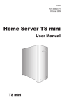
SOFTWARE AND HARDWARE SOLUTIONS FOR THE EMBEDDED WORLD
MikroElektronika
Development tools - Books - Compilers
PICPLC 16
User’s Manual
with on board
USB
2.0 programmer
PICPLC16 is a system designed for controlling industrial systems
and machines. 16 inputs with optocouplers and 16 relays (up to
10A) can satisfy many industrial needs. PICPLC16 can serve as
remote control system by means of RS-485 communication.
Software and Hardware
solutions for Embedded World
MikroElektronika
Development
tools
PICPLC 16 User’s Manual
First edition
November
2005
No part of this manual, including the product and software described in it, may be
reproduced, transmitted, transcribed, stored in a retrieval system, or translated into
any language in any form or by any means, except documentation kept buy the purchaser for backup purposes, without the express written permission of
MikroElektronika company.
Product warranty or service will not be extended if the product is repaired, modified
or altered, unless such repair, modification or alteration is authorized in writing by
MikroElektronika.
MIKROELEKTRONIKA PROVIDE THIS MANUAL “AS IS” WITHOUT WARRANTY
OF ANY KIND, EITHER EXPRESS OR IMPLIED, INCLUDING BUT NOT LIMITED
TO THE IMPLIED WARRANTIES OR CONDITIONS OF MERCHANTABILITY OR
FITNESS FOR A PARTICULAR PUROSE.
IN NO EVENT SHALL MIKROELEKTRONIKA, ITS DIRECTORS, OFFICERS,
EMPLOYEES OR DISTRIBUTORS BE LIABLE FOR ANY INDIRECT , SPECIAL,
INCIDENTAL, OR CONSEQUENTIAL DAMAGES(INCLUDING DAMAGES FOR
LOSS OF PROFITS, LOSS OF BUSINESS, LOSS OF USE OR DATA, INTERRUPTION OF BUSINESS AND THE LIKE) EVEN IF MIKROELEKTRONIKA HAS BEEN
ADVISED OF THE POSSIBILITY OF SUCH DAMAGES ARISING FROM ANY
DEFECT OR ERROR IN THIS MANUAL OR PRODUCT.
SPECIFICATION AND INFORMATION CONTAINED IN THIS MANUAL ARE FURNISHED FOR INTERNATIONAL USE ONLY, AND ARE SUBJECT TO CHANGE AT
ANY TIME WITHOUT NOTICE , AND SHOULD BE CONSTRUED AS A COMMITMENT BY MIKROELEKTRONIKA
MikroElektronika assumes no responsibility or liability for any errors or inaccuracies
that may appear in this manual, including the product and software described in it.
Product and corporate names appearing in this manual may or may not be registered trademarks or copyrights of their respective companies, and are used only for
identification or explanation and to the owners benefit, without intent to infringe.
USB
PICPLC
16
MIKROELEKTRONIKA SOFTWARE AND HARDWARE SOLUTIONS FOR THE EMBEDDED WORLD
page
2
MikroElektronika
Development
tools
CONTENTS
USB
PICPLC
16
CONNECTING THE SYSTEM
page 4
INTRODUCTION
page 5
DESCRIPTION OF THE DEVELOPMENT SYSTEM
page 6
Jumpers
page 6
MCU socket
page 7
Power Supply
page 9
Power Supply Supervisor & Reset circuit
page 11
On-board USB programmer
page 12
RS-232 Communication
page 14
RS-485 Communication
page 16
PS/2 (Keyboard) connector
page 18
Optocouplers
page 19
Releys
page 21
Direct port access
page 23
MIKROELEKTRONIKA SOFTWARE AND HARDWARE SOLUTIONS FOR THE EMBEDDED WORLD
page
3
CONTENTS
PICPLC 16 User’s Manual
CONNECTING THE SYSTEM
PICPLC 16 User’s Manual
MikroElektronika
Development
tools
CONNECTING THE SYSTEM
The development system box contains a development system, CD, USB cable and
serial cable.
Step no.1 The first thing to do is to take the system out of a box. Unpack the USB cable and
connect it to the PC. Please use USB ports from the back of the PC, with direct contact to the motherboard.
Step no.2 Connect MCU power supply to the PICPLC16 board.
Step no.3 Connect the USB cable to the PICPLC16 board.
Step no.4 The PC will start the procedure for installing the USB driver for the on-board USB
2.0 programmer. Follow the procedure from the document ‘ Installing Driver for
USB programmer’ and install the USB driver.
Step no.5 Copy PICFLASH2.exe file to the folder of your choice. You can find this file in the
PICFLASH folder on the CD.
Step no.6 Run and use PICFLASH2 as explained in the document ‘PICflash programmer’.
After these 6 steps, your PICPLC16 is installed and ready for use. You should try
to read a program from the chip or to load an example from the examples folder.
page
4
MIKROELEKTRONIKA SOFTWARE AND HARDWARE SOLUTIONS FOR THE EMBEDDED WORLD
USB
PICPLC
16
MikroElektronika
Development
tools
PICPLC 16 User’s Manual
The PICPLC16 development system is a industrial development board for
Microchip PIC microcontrollers. It allows PIC microcontrollers to be interfaced
with external circuits and a broad range of peripheral devices, allowing the user to
concentrate on software development.
Figure 1 illustrates the development board. On a silkscreen, there are identification
marks beside each component. These marks describe connections to the microcontroller, operation modes, and provide some useful notes. The need for additional
schematics is minimized as all the information is printed on the board.
Figure 1.
PICPLC16 development board
USB
PICPLC
16
MIKROELEKTRONIKA SOFTWARE AND HARDWARE SOLUTIONS FOR THE EMBEDDED WORLD
page
5
INTRODUCTION
INTRODUCTION
PICPLC 16 User’s Manual
MikroElektronika
Development
tools
JUMPERS
JUMPERS
Jumpers can break or establish a connection between two points. Beneath the plastic cover of the jumper is a metal contact, which makes a connection when the
jumper is placed between two disconnected pins.
For example J14 is used to connect or disconnect Tx line for RS-232 Communication. Connection is made when the jumper is placed between two contacts.
Figure 2.
Jumper is ON
Jumper as a
switch
Jumper is OFF
More often, jumpers are used as a selector between two possible connections using
a three pin connector. As illustrated in Fig. 3, middle connector can be connected to
the left or right pin, depending on the jumper’s position.
.
Figure 3.
All lines are disconneced
Jumper as a
multiplexer
Left line is selected
Right line is selected
page
6
MIKROELEKTRONIKA SOFTWARE AND HARDWARE SOLUTIONS FOR THE EMBEDDED WORLD
USB
PICPLC
16
MikroElektronika
Development
tools
MCU SOCKET
The PICPLC16 development board support a 40-pin microcontrollers in DIP40
package as shown on the following picture:
Figure 4.
USB
PICPLC
16
MCU socket
MIKROELEKTRONIKA SOFTWARE AND HARDWARE SOLUTIONS FOR THE EMBEDDED WORLD
page
7
MCU SOCKET
PICPLC 16 User’s Manual
MikroElektronika
Development
tools
PICPLC 16 User’s Manual
MCU CARD
The microcontroller’s pins are routed to various peripherials as illustrated in Figure
5. All ports have direct connections to Direct Port Access connectors. Such connectors are typically used for connecting external peripherials to the board, or for providing useful points for connecting digital logic probes.
Some of the pins are connected to other peripherials such as optocouplers, RS-232
communication, RS-485 communication, etc.
Figure 5.
System connection
Input optocouplers
Port
connector
vcc
Pull-up/down
resistors
vcc
VCC
OC3
VCC
RA4
GND
HCPL2630
MCLR
RB7
RA0
RB6
RA1
RB5
RA2
RB4
RA3
RB3
RA4
RB2
RE0
vcc
RE1
RE2
VDD
VSS
OSC1
OSC2
RC0
RC1
PICxxxx
RA5
RB1
RB0
VDD
VSS
RD7
RD6
RD5
RD4
RC7
RC6
RC2
RC5
RC3
RC4
RD0
RD3
RD1
RD2
page
8
MIKROELEKTRONIKA SOFTWARE AND HARDWARE SOLUTIONS FOR THE EMBEDDED WORLD
USB
PICPLC
16
MikroElektronika
Development
tools
PICPLC 16 User’s Manual
PICPLC16 have three kind of power supply - MCU power supply, reley power supply and optocoupler power supply.
The MCU power supply can be AC or DC, with a voltage between 8V and 16V. The
reley power supply can be AC with a voltage between 12V and 15V, or DC with
voltage between 15V and 18V. Optocoupler power supply is 12V DC. In Figure 6
and Figure 7 you can see power supply connectors.
Figure 6.
MCU, reley and optocoupler power supply connectors
GND MCU power supply
(two pins on the right
+7-10V side of the connector)
+15V GND
Reley power supply
(two pins on the left
side of the connector)
Optocoupler power
supply (all four pins
on the connector are
inputs for 12V DC)
5V DC
GND output
External reley power supply connector
Reley power supply can be internal or
external. In case of external power supply 12V DC must be connected to two
pins on the left side of the connector
which is placed on the lower right side
of the development board. Selection is
made with jumper J9 as shown on the
next page.
GND
12V DC
external input
USB
PICPLC
16
Figure 7.
12V DC
output
GND
MIKROELEKTRONIKA SOFTWARE AND HARDWARE SOLUTIONS FOR THE EMBEDDED WORLD
page
9
POWER SUPPLY
POWER SUPPLY
MikroElektronika
Development
tools
PICPLC 16 User’s Manual
Power supply schematic
POWER SUPPLY
Figure 8.
CN3
1
2
3
4
Reley power supply
Optocoupler power (12V)
CN2
12V internal
12V external
OCVCC
1
VCC (output)
2
D33
1N4007
REG2
7812
12-15V AC / 15-18 DC
+
1
Vin
Vout
+U12
+U12ext
3
GND
2
E5...8
470uF
CN1
VCC-REL
E13...16
470uF
C10
100nF
C9
100nF
D22
1N4007
3
MCU power (5V)
REG1
7805
4
9V AC/DC
+
1
Vin
Vout
VCC
3
GND
+U12 (output)
2
+U12ext (input)
Relay power (12V)
1
2
3
2
E1...4
470uF
C7
100nF
C8
100nF
E9...12
470uF
1
4
CN24
page
10
MIKROELEKTRONIKA SOFTWARE AND HARDWARE SOLUTIONS FOR THE EMBEDDED WORLD
USB
PICPLC
16
MikroElektronika
Development
tools
PICPLC 16 User’s Manual
In the industrial enviorment it is very important to have reliable device that will
continue working on every posible condition. The most important component on
every electronic device is a stabile power supply, but in the harsh enviorment there
can be some deviance from nominal values. Power supply supervisor monitor
power supply level and restart the microcontroller if the level is to low or to high.
Reset button is also connected to power supply supervisor, which generates reset
signal when button is pressed.
Figure 9.
Power supply supervisor schematic
VCC
VCC
VCC
R63
100
R66
10K
REF
RESET
BUTTON
C28
100nF
Figure 10.
SENSE
CT
RESET
GND
RESET
PICPLC
16
RESET OUT (to MCU)
R64
10K
E27
10uF
Reset button
Figure 11.
USB
R65
10K
VCC
RESIN
TL7705
C26
100nF
VCC
Power supply supervisor
MIKROELEKTRONIKA SOFTWARE AND HARDWARE SOLUTIONS FOR THE EMBEDDED WORLD
page
11
POWER SUPPLY SUPERVISOR & RESET CIRCUIT
POWER SUPPLY SUPERVISOR & RESET CIRCUIT
MikroElektronika
Development
tools
PICPLC 16 User’s Manual
ON-B
BOARD USB PROGRAMMER
ON-BOARD USB PROGRAMMER
There is no need for the use of external equipment during programming, as the
PICPLC16 development system has its own on-board USB programmer.
All you need to do is connect MCU power supply to development board, connect
the system to a PC using the USB cable, and enable Development MODE by setting jumpers J1, J2, J3 and J4 to the left side position. Then, load your program into
the microcontroller via the PICflash2 programming software, which is supplied
with the board.
On-Board USB programmer
Figure 12.
By enabling or disabing Development MODE you connect or disconnect the programmer from the rest of the board. That is very important when working in industrial enviorment, where application of PICPLC16 can include high voltages and/or
currents and do possible damage to programmer (the programmer is secured by disabling Development MODE!).
page
12
MIKROELEKTRONIKA SOFTWARE AND HARDWARE SOLUTIONS FOR THE EMBEDDED WORLD
USB
PICPLC
16
MikroElektronika
Development
tools
Development MODE
VCC
RB6
RA1
RB5
RA2
RB4
RA3
RB3
RA4
RB2
OSC1
OSC2
RC0
RC1
RB0
VDD
RB7
J1
VSS
RD7
RD6
RB6
RD5
J2
RD4
RC7
RC6
RC2
RC5
RC3
RC4
RD0
RD3
RD1
RD2
MCLR
J3
VCC
POWER
R5
VSS
VCC
RB1
R2
VDD
USB
CONNECTOR
R1
RE2
USB LINK
PICflash On-Board
USB programmer
RE1
PICxxxx
RE0
VCC
DISABLED
R6
RA0
RA5
ENABLED
RB7
MCLR
CN9
1
VCC
2
D3
USB
D+
4
GND
RSTbut
J4
VCC
100n
R1
RESET
BUTTON
RESET OUT
TO DEVELOPMENT
BOARD PERIPHERALS
Supply Voltage
supervisor
RESET IN
USB
PICPLC
16
MIKROELEKTRONIKA SOFTWARE AND HARDWARE SOLUTIONS FOR THE EMBEDDED WORLD
page
13
ON-B
BOARD USB PROGRAMMER
On-Board USB programmer schematic
100n
Figure 13.
PICPLC 16 User’s Manual
MikroElektronika
Development
tools
PICPLC 16 User’s Manual
RS-2
232 COMMUNICATION
RS-232 COMMUNICATION
RS-232 communication enables point-to-point data transfer. It is commonly used in
data acquisition applications, for the transfer of data between the microcontroller
and a PC. Since the voltage levels of a microcontroller and PC are not directly compatible with each other, a level transition buffer such as the MAX232 must be used.
Figure 14.
RS-232 connector
Rx
Tx
RS-232 connector
(two pins on the
right side)
PICPLC16 development board have one RS-232 communication device. In order to
provide a more flexible system, the microcontroller is connected to the MAX232
through two jumpers. Jumper J13 and J14 are used to connect Rx and Tx lines from
microcontroller to RS-232 port.
RS-232 jumpers
Figure 15.
RS-232 Rx and Tx
jumpers
page
14
MIKROELEKTRONIKA SOFTWARE AND HARDWARE SOLUTIONS FOR THE EMBEDDED WORLD
USB
PICPLC
16
MikroElektronika
Development
tools
RS-2
232 COMMUNICATION
PICPLC 16 User’s Manual
Figure 16.
RS-232 Schematic and connection to the PC
VCC
CN2
E6
10uF
1
VCC (output)
2
C1+
E3
10uF
CN8
4
GND
C1-
T1out
C2+
R1in
C2-
R1out
Tx
V-
T1in
2
T2out
T2in
1
R2in
RC6
RB6
RA1
RB5
RA2
RB4
RA3
RB3
RA4
RB2
RA5
RE0
J14
3
V+
RB7
RA0
RE1
VCC
RE2
VDD
R2out
VSS
E5
10uF
MAX232
OSC1
RC7
Rx
J13
RS-232
Disabled
RS-232
Enabled
OSC2
RC0
RC1
PICxxxx
E4
10uF
VCC
MCLR
RB1
RB0
VDD
VSS
RD7
RD6
RD5
RD4
RC7
RC6
RC2
RC5
RC3
RC4
RD0
RD3
RD1
RD2
Serial Cable
1
6
Rx
Tx
9
5
Figure 17.
RS-232 jumpers and MAX232 chip
USB
PICPLC
16
MIKROELEKTRONIKA SOFTWARE AND HARDWARE SOLUTIONS FOR THE EMBEDDED WORLD
page
15
MikroElektronika
Development
tools
PICPLC 16 User’s Manual
RS-4
485 COMMUNICATION
RS-485 COMMUNICATION
RS-485 communication enables point-to-point and point-to-multipoint data transfer. It is commonly used for data transfer between several microcontrollers. LTC485
interface tranciever is used for transforming signal from microcontroller’s Rx and
Tx lines to differential signal on A and B output lines.
Figure 18.
RS-485 connector
A RS-485 connector
(two pins on the
B
left side)
PICPLC16 development board have one RS-485 communication device. In order to
provide a more flexible system, the microcontroller is connected to the LTC485
through three jumpers. Jumper J10, J11 and J12 are used to connect Rx, Rt and Tx
lines from microcontroller to RS-485 port.
RS-485 jumpers
Figure 19.
RS-485 Rx, Rt and
Tx jumpers
page
16
MIKROELEKTRONIKA SOFTWARE AND HARDWARE SOLUTIONS FOR THE EMBEDDED WORLD
USB
PICPLC
16
MikroElektronika
Development
tools
RS-485 schematic and connection to other RS-485 modules
RB7
MCLR
RA0
RB6
RA1
RB5
RA2
RB4
RA3
RB3
RA4
RB2
RE0
OSC1
OSC2
RC0
RE2
VSS
J11
RD7
RD6
Tx
RC6
RD5
RD4
RC7
RC1
RC6
RC2
RC5
RC3
RC4
RD0
RD3
RD1
RD2
CN8
J12
Rx
RO
VCC
RE
B
DE
A
DI
GND
B-485
4
VSS
VDD
Rt
3
VDD
VCC
RB1
RB0
2
RE2
RS-485
Disabled
RS-485
Enabled
1
RE1
PICxxxx
RA5
VCC
RS-4
485 COMMUNICATION
Figure 20.
PICPLC 16 User’s Manual
A-485
LTC485
RC7
J10
2nd RS-485
MODULE
3rd RS-485
MODULE
Figure 21.
RS-485 jumpers and LTC485 chip
USB
PICPLC
16
MIKROELEKTRONIKA SOFTWARE AND HARDWARE SOLUTIONS FOR THE EMBEDDED WORLD
page
17
MikroElektronika
Development
tools
PICPLC 16 User’s Manual
PS/2 (KEYBOARD) CONNECTOR
PS/2 (KEYBOARD) CONNECTOR
Keyboards consist of a large matrix of keys, all of which are monitored by an onboard processor (called the "keyboard encoder".) The specific processor varies
from keyboard-to-keyboard but they all basically do the same thing: Monitor which
key(s) are being pressed/released and send the appropriate data to the MCU. This
processor takes care of all the debouncing and buffers any data in its 16-byte buffer,
if needed. All communication between the host and the keyboard uses an IBM protocol.
Figure 22.
PS/2 (Keyboard) connector
NC
CLK
RB7
RA0
RB6
RA1
RB5
RA2
RB4
RA3
RB3
RA4
RB2
RA5
RE0
NC
DATA
RE1
VCC
RE2
VDD
VCC
VSS
OSC1
OSC2
Figure 23.
PS/2 (Keyboard) schematic
PS2
CONNECTOR
DATA
NC
GND
VCC
CLK
NC
RC0
PICxxxx
+5V
MCLR
RC1
VDD
VSS
RD7
RD6
RD5
RD4
RC7
RC6
RC2
RC5
RC3
RC4
RD0
RD3
RD1
RD2
page
18
RB1
RB0
MIKROELEKTRONIKA SOFTWARE AND HARDWARE SOLUTIONS FOR THE EMBEDDED WORLD
USB
PICPLC
16
MikroElektronika
Development
tools
OPTOCOUPLERS
PICPLC16 have 16 optocouplered inputs. It is widely used in industrial applications
where inputs must be galvanized (electrically isolated from the rest of the development board). All that is done to protect microcontroller from electrical pulses that
might occur on input lines.
Figure 24.
Optocouplers and their connectors
In order to be electricaly isolated from the rest of the board, input circuit must have
it’s own power supply (12V DC). Optocoupler chip have two LED’s on the input
and two open collector transistors on the output pins. First 8 optocoupler outputs
are connected to microcontroller’s RA(E) port and second 8 outputs are conected to
microcontroller’s RC port. Ports RA(E) and RC must be on high level eg. they must
be pulled-up by putting jumpers J5 and J7 on upper position.
USB
PICPLC
16
MIKROELEKTRONIKA SOFTWARE AND HARDWARE SOLUTIONS FOR THE EMBEDDED WORLD
page
19
OPTOCOUPLERS
PICPLC 16 User’s Manual
MikroElektronika
Development
tools
PICPLC 16 User’s Manual
CN3
1
3
2
4
OPTOCOUPLERS
POSSIBLE INPUT FOR
OPTOCOUPLERS
CN4
2
1
3
4
Optocoupler power (12V)
OCVCC
VCC
VCC
R15
330
OCVCC
R16
10K
R18
10K
OCVCC
OCVCC
OC1
VCC
D6
1N4148
D7
1N4148
R20
10K
R22
10K
GND
OCVCC
HCPL2630
R17
330
R19
330
D8
1N4148
D9
1N4148
R21
330
OC2
VCC
GND
HCPL2630
J5
1
Pull-up line is
connected
RB7
RA0
RB6
RA1
RB5
RA2
RB4
RA3
RB3
2 RA0
RA4
RB2
3 RA1
RA5
RP1
1
4 RA2
RE0
5 RA3
6
7
8
9
RA4
RA5
RE1
RE2
VCC
RE1
RE2
VDD
VSS
OSC1
OSC2
RC0
RC1
Figure 25.
Optocouplers schematic
PICxxxx
MCLR
VCC
2
3
Before button is
pressed level is
high (inactive state)
When button is
pressed level is
low (active state)
RB1
RB0
VDD
VSS
RD7
RD6
RD5
RD4
RC7
RC6
RC2
RC5
RC3
RC4
RD0
RD3
RD1
RD2
page
20
MIKROELEKTRONIKA SOFTWARE AND HARDWARE SOLUTIONS FOR THE EMBEDDED WORLD
USB
PICPLC
16
MikroElektronika
Development
tools
RELEYS
In order to control devices that operates on high voltage and/or current, PICPLC16
have 16 releys connected to microcontroller ports RB and RD. Because releys have
higher operating voltage and higher current consumption they have separated power
supply (12V DC). It can be internal when connected together with MCU power supply or external. You select one of these two power supplies by setting jumper J9 in
appropriate position.
Figure 26.
Releys and their connectors
Microcontroller’s ports RB and RD can’t provide necessary current for direct driving of releys so they are connected to ULN2804 Darlington drivers. Ports RB and
RD must be on low level eg. pulled-down so the releys are switched on when microcontroller puts logical one on their outputs. Each reley have one LED indicator connected parallel to him so it shows when reley is switched on. There are three contacts on reley’s output: working contact, non-working contact and common contact.
Common contacts of every four releys are also provided on development board connectors. Optionaly you can add varistor to development board depending on reley’s
working voltage and current (it is connected between working and common contacts).
USB
PICPLC
16
MIKROELEKTRONIKA SOFTWARE AND HARDWARE SOLUTIONS FOR THE EMBEDDED WORLD
page
21
RELEYS
PICPLC 16 User’s Manual
MikroElektronika
Development
tools
Figure 27.
RELEYS
PICPLC 16 User’s Manual
Releys schematic
J6
1
VCC
2
3
RP2
1
Pull-down line
is connected
RB7 2
RB6 3
RB5 4
RB4 5
RB3
RB2
RB1
RB0
6
7
8
9
WORKING CONTACT
RB7
RA0
RB6
RA1
RB5
RA2
RB4
RA3
RB3
RA4
RB2
VDD
VSS
OSC1
OSC2
RC0
RC1
VCC-REL
R31
1K
R32
1K
LD1
LD2
VCC-REL
ULN2804
RB1
RB0
VARISTOR (OPTIONAL)
VDD
VSS
RD7
RD6
RD5
RD4
W0 - Working contact on Reley0
NW0 - Non-working contact on Reley0
W1 - Working contact on Reley1
NW1 - Non-working contact on Reley1
RC7
RC6
RC2
RC5
RC3
RC4
RD0
RD3
RD1
RD2
1
CN15
2
W1
RE2
VCC-REL
3
NW1
VCC
OUT2
OUT3
OUT4
OUT5
OUT6
OUT7
OUT8
COM
W0
RE1
OUT1
IN1
IN2
IN3
IN4
IN5
IN6
IN7
IN8
GND
NW0
RE0
PICxxxx
RA5
RLY2
RLY1
U6
MCLR
NON-WORKING CONTACT
4
1
CN16
CN19
2
3
4
CN20
page
22
MIKROELEKTRONIKA SOFTWARE AND HARDWARE SOLUTIONS FOR THE EMBEDDED WORLD
USB
PICPLC
16
MikroElektronika
Development
tools
DIRECT PORT ACCESS
All microcontroller input/output pins can be accessed via connectors placed along
the right-hand side of the board. For each of the ports RA(E), RB, RC and RD there
is one 10-pin connector providing Vdd, GND and up to eight port pins.
These connectors can be used for system expansion with external boards such as
Compact Flash, CAN, serial GLCD etc. Ensure that the on-board peripherials are
diconnected from microcontroller by setting the appropriate jumpers, while external peripherals are using the same pins. The connectors can also be used for attaching logic probes or other test equipment.
Figure 28.
Direct port access connectors
USB
PICPLC
16
MIKROELEKTRONIKA SOFTWARE AND HARDWARE SOLUTIONS FOR THE EMBEDDED WORLD
page
23
DIRECT PORT ACCESS
PICPLC 16 User’s Manual
PICPLC 16 User’s Manual
DIRECT PORT ACCESS
MikroElektronika
Development
tools
J6
1
VCC
2
3
Pull-up line is
connected
RP2
1
RB0 2
RB1 3
RB2 4
RB3 5
RB4
RB5
RB6
RB7
MCLR
RB7
RA0
RB6
RA1
RB5
RA2
RB4
RA3
RB3
RA4
RB2
RE0
RE1
VCC
RE2
VDD
VSS
OSC1
OSC2
RC0
RC1
PICxxxx
RA5
Pull-down line
is connected
All lines
are disconnected
6
7
8
9
RB1
RB0
VDD
VSS
CN12
RB0
RB1
RB2
RB3
RB4
RB5
RB6
RB7
RD7
RD6
RD5
RD4
RC7
RC6
RC2
RC5
RC3
RC4
RD0
RD3
RD1
RD2
VCC
HEADER 5x2
Figure 29.
Port B connection to microcontroller
page
24
MIKROELEKTRONIKA SOFTWARE AND HARDWARE SOLUTIONS FOR THE EMBEDDED WORLD
USB
PICPLC
16
MikroElektronika
Development
tools
PICPLC 16 User’s Manual
If you are experiencing problems with any
of our products or you just want additional
information, please let us know. We are
committed to meet every your need.
Technical Support :
[email protected]
If you have any other question, comment
or a business proposal, please contact us:
E-mail: [email protected]
Web: www.mikroe.com
USB
PICPLC
16
MIKROELEKTRONIKA SOFTWARE AND HARDWARE SOLUTIONS FOR THE EMBEDDED WORLD
page
25