1
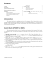
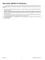
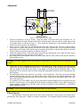
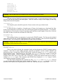
FIBER SIGMA 105 Hillcrest Road Flemington, New Jersey 08822-7173 U.S.A. Tel: +(908) 377-0763 Fax: +(908) 547-0095 E-mail: [email protected] Web: http://www.fibersigma.com AUTOMATIC FIBER LOADER USER’S MANUAL Version 1.08a, August 2012 this page intentionally blank Contents Contents 1 Introduction 1 Quick Start (2POINT for DOS) 1 Quick Start (2POINT for Windows) 2 Installation Hardware Installation Software Installation (2POINT for Windows) Software Installation (2POINT for DOS) Alignment 3 3 4 4 5 Fiber Payout System Operation Wide Option Operation Under Windows Operation Under DOS 5 7 7 7 7 Common Problems 9 1. The fiber buckles outside the guide plates. 9 2. Fiber does not feed correctly. 9 Introduction This manual describes the installation and use of the Automatic Fiber Loader which is used to automate strength measurement of optical fibers using our 2-Point Bending Apparatus. The loader makes it possible to make many strength and fatigue measurements with different experimental parameters, all without operator intervention. Quick Start (2POINT for DOS) This section provides a brief overview of installation and operation of the Automatic Fiber Loader. It is assumed that the Two-Point Bend equipment is operating correctly and that the Loader is correctly installed. 1. Copy the 2POINT.EXE and LOADER.EXE programs from the Fiber Sigma distribution disc to a subdirectory on the DOS path. 2. Copy the files LOAD-TST.INI, LOAD-TST.001 and LOAD-TST.002 from the distribution diskette to the subdirectory in which you will be working. 3. Edit the file LOAD-TST.INI making sure that it has the correct groove depth set in ZeroOffset parameter and, if you are using the V-groove faceplates, that the GrooveAngle parameter is set to 90°. 4. Connect the cable on the Loader to the “Loader” connector on the rear panel of the Bend Control Unit. Turn everything on. 5. Load a fiber through the tube on the left of the loader, between the left-hand pinch rollers and about 12 mm into the gap between the two guide plates (see Figure 4 below). 6. Run the 2POINT program by typing 2POINT LOAD-TST.INI at the DOS prompt. 7. Select start automatic Control in the Run Experiment menu and the apparatus should break two fibers at each of two different faceplate speeds. LOADER User's Manual 1 Quick Start Quick Start (2POINT for Windows) This section provides a brief overview of installation and operation of the Automatic Fiber Loader. It is assumed that the Two-Point Bend equipment is operating correctly and that the Loader is correctly installed. 1. Connect the cable on the Loader to the “Loader” connector on the rear panel of the Bend Control Unit. Turn everything on. 2. V-groove faceplates should be installed for correction operation of the Automatic Loader. Start 2POINT for Windows and make sure that the correct groove depth is specified in the Experiment Parameters section of the main window of 2POINT. Also, the groove angle should be set to 90° for Vgroove faceplates. 3. Load a fiber through the tube on the left of the loader, between the left-hand pinch rollers and about 12 mm into the gap between the two guide plates (see Figure 4 below). 4. Click on Automatic mode. Click Read to load a script file from disc – sample scripts are included on the distribution disc. 5. Click Run script. Quick Start 2 LOADER User's Manual Installation Hardware Installation Installation of the automatic loader is slightly different depending on whether the Two-Point Bend Apparatus is based on an Aerotech translation stage (for systems shipped before November 2001) or an ALM translation stage (for systems shipped since November 2001). Differences for the two translation stages are denoted by “[Aerotech]” and “[ALM]”. The Automatic Loader is supplied ready assembled. The following steps are only required if the equipment has been disassembled for some reason. (If the equipment is disassembled, it will avoid later problems if the positions of the standoffs are marked on the base plate.) 1. Attach four 33 mm [Aerotech] or 19 mm [ALM] and four 52 mm long hex standoffs on the base plate using ¼-20¾" set screws in positions shown in Figure 1. Make sure the set screws do not project below the bottom of the plate. For the standard Automatic Loader, use the green and blue positions for the 52 mm standoffs; use the red and blue positions for the Wide Option Automatic Loader. Note that some ALM systems have a different arrangement for the standoffs under the translation stage so might look a little different from Figure 1. However, the purpose of the standoffs is to align the ends of the faceplates with the slot between the shim plates – if the wrong positions are used for the standoffs the misalignment will be obvious. Aerotech translation stage 33 mm standoffs ALM translation stage ALM translation stage (before mid 2007) (mid 2007 onwards) 19 mm standoffs 19 mm standoffs 52 mm standoffs 52 mm standoffs 52 mm standoffs Figure 1: Positions for attaching hex standoffs to the base plate for the Aerotech and ALM translation stages. 2. Turn off power to the two-point bend apparatus (both on the motor drive and the Bend Control Unit). 3. [Aerotech] Remove the top mounting plate by removing the four ¼-20 stainless steel bolts. Remove the mounting plate below by removing four #4/40 screws. This exposes the translation stage lead screw. The platform can be moved by turning the knurled knob on the motor to expose the four ¼" diameter mounting holes in the base of the stage. Mount the translation stage on the hex standoffs as shown in Figure 2, using four ¼-203/8" bolts. Replace the mounting plate and top plate on the translation stage. Warning: Avoid getting any dust or lose items inside the translation stage. This might cause permanent and serious damage to the precision mechanism of the stage. 3. [ALM] Attach the adapter plate to the underside of the translation stage using two 10-32½" screws. Now attach the adapter plate to two of the hex standoffs using two ¼-203/8" screws as shown in Figure 2. Note that for systems shipped from mid 2007 onwards the adapter plate is somewhat larger. LOADER User's Manual 3 Installation Figure 2: Orientation for mounting the translation stage and loader assembly on the base plate for the Aerotech and ALM translation stages. 4. If they are not already installed, put the single V-groove faceplates on the mounting arms, as shown in Figure 2. Make sure the faceplates are carefully aligned using the instructions in the Two-Point Bend Apparatus manual. 5. Attach the loader assembly to the four longer hex standoffs using four ¼-203/8" bolts, as shown in Figure 2. Make sure that the fiber guide tube projects to the left of the loader as shown in the figure. 6. Make all electrical connections to the translation stage and check its operation. Now attach the D-9 connector on the cable from the loader mechanism to the socket marked “Loader” on the rear panel of the Bend Control Unit. Software Installation (2POINT for Windows) Support for the automatic loader is built in to the 2POINT for Windows software. See the 2POINT for Windows manual (either the printed copy or the online help file) for information. Software Installation (2POINT for DOS) 1. Copy the 2POINT.EXE and LOADER.EXE programs from the Fiber Sigma distribution diskette to a subdirectory in the DOS path. 2. Copy the files LOAD-TST.INI, LOAD-TST.001 and LOAD-TST.002 from the Fiber Sigma distribution diskette to the subdirectory in which you are working. 3. Edit the file making sure that it has the correct groove depth set in the ZeroOffset parameter and, if you are using the V-groove faceplates, that the GrooveAngle parameter is set to 90°. (LOAD-TST.INI is a profile file for the 2POINT program – see the Two Point Bend Apparatus manual for further details.) 4. Check correct operation of the Loader by executing the following command from the DOS prompt: LOADER D 100 nn replacing nn by the number of the printer port to which the Bend Control Unit is connected (default 1; any other value would be set by the BenderPort profile parameter). Both pinch rollers on the Loader should rotate immediately after executing this command (the right-hand roller will rotate a little longer than the right-hand ones). Installation 4 LOADER User's Manual Alignment Figure 3: Key components of the loader. 1. Open the faceplates to a gap of 20 mm. Align the loader so that the ends of the faceplates are 1 to 2 mm from the guide plates and the inside faces of the faceplates line up with the inside edges of the two smaller shims, as shown in Figure 3. There should be enough play in the mounting holes of the loader base plate to achieve this alignment. 2. Insert a piece of fiber from the left through the guide tube, between the first pair of pinch rollers, between the two guide plates and out between the second pair of pinch rollers. Now rotate the left-hand pinch rollers to feed more fiber into the gap between the guide plates so that the fiber buckles and feeds a loop of fiber between the faceplates, as shown in Figure 3. 3. Adjust the height and tilt of the guide plates using the three adjustment screws until the fiber loop is accurately aligned over the grooves in the faceplates. 4. By rotating the left hand pinch rollers some more, check that the fiber reliably feeds into the middle of the faceplate grooves. Warning: Accurate alignment of the fiber and the faceplate grooves is critical for correct operation of the loader. 5. Loosen the set screw clamping the guide tube in its mounting post. Slide the tube to the right until the end is close to but not touching the pinch rollers. Adjust the height of the mounting post with washers until the height of the tube is the same as the height as the gap between the guide plates. Poor alignment here can cause the fiber to buckle outside the guide plates and hence fail to feed properly into the faceplates. 6. Put the length of fiber to be tested on a reel with a 1 inch central hole. Place this reel on the turntable included with the loader in such a way that the fiber comes off the reel in line with the guide tube. The fiber, when threaded through the guide tube into the loader, should not pass through a sharp bend at the inlet of the guide tube. If a suitable reel is not available, any pay out system can be used providing the force required to pay out the fiber is not too great. For example, the fiber could be carefully coiled in a tray so that it can pay out without tangling. Alternatively, the fiber can be fed into a closed box with a small hole – it should not tangle when it is fed out. Warning: The pay out force should be small for the loader to work correctly. Fiber Payout The Automatic Loader only pulls on the fiber with a modest force. Any greater force would require pinching the fiber quite hard – which we consider undesirable. The turntable supplied with the equipment LOADER User's Manual 5 Installation can be used. However, fiber reels are often heavy and the loader might not be able to pull hard enough and the fiber will slip. In the worst case this can lead to misfeeding the fiber. Therefore, a small light reel of fiber should be used. Alternatively the fiber could be laid loosely in a container. However, loops of fiber necessarily are twisted. If the loader pulls fiber from a loose coil, the twisting will eventually case knotting or tangling of the fiber. Therefore loose coils should only be used for relatively short lengths of fiber. Figure 4: Fiber dispenser. A compact alternative to reels or loose coils of fiber is the fiber dispenser shown in Figure 4. This device takes advantage of the fact that if the fiber is laid down in a figure-8 shape, there is no net twisting of the fiber. The metal feed tube in the top of the dispenser lid should be pointed in a direction perpendicular to the centers of the two cylinders, as shown in the photograph. The end of the fiber is inserted into the tube. The end of the fiber should come out through the narrow gap between the cylinders – if it does not the guide tube can be rotated so that the fiber goes in the right direction. Once through the gap between the cylinders, the fiber should be pulled to one side and attached to the base of the dispenser using a small piece of adhesive tape (blue tape is shown in the photograph). You can now continue to feed the fiber into the tube – it will automatically lay itself down in the shape of a figure 8. Note that the fiber must be fed into the dispenser without any twist in it – this can be achieved by paying out the fiber from a reel on the turntable. Once enough fiber has been inserted into the dispenser for the measurement in hand, the fiber can be cut and the cut end fed into the fiber loader as described earlier. The loader motors can easily pull the fiber out of the dispenser. Depending on the fiber thickness and the tackiness and hardness of the fiber coating, some fibers will lay down flat in the dispenser. However, others will twist up and form a figure 8 dumbbell inside the dispenser! Even though this ball of fiber looks tangled, the crisscrossing of subsequent loops tends to keep the loops untangled and separate. No problems have been found feeding a few meters of fiber even when balled up like this. Note that only a few meters of fiber are needed for making a standard ITM-13 dynamic fatigue measurement. Installation 6 LOADER User's Manual System Operation Figure 5: Starting position of fiber in the loader. Fiber should be placed in the loader in the position shown in Figure 5, with the end level with the inside edge of the left-hand shim. Wide Option Figure 6: Operation of the Wide Option Automatic Loader with thin fiber. A Wide Option is available for the Automatic Loader for use with thicker fiber (up to about 300 µm glass diameter). The shim plates are further apart to allow space for the thicker fiber to bend. It also uses thicker shim plates. Apart from the difference in dimensions, the operation is identical to the standard Loader. The Wide Option can be used for thinner fiber by restricting the width of the slot as shown in Figure 6. An extra piece of shim is included (shown green in Figure 6) which can be slipped into the slot. Once in position it can be held there by dropping two screws into the two holes in the shim plates and shim. The shim has two small holes (shown in red) which can be used to push and pull the shim into position or to remove it. Operation Under Windows Operation of the loader using 2POINT for Windows is similar to operation with the DOS version. However, details of operating the loader under Windows are in the 2POINT for Windows manual (either the printed copy or the online help file) for information. Operation Under DOS The 2POINT for DOS program is run after reading in a suitable profile file (either by placing the profile file name on the command line or reading the profile from the Read/Write Profile menu). To see the loader operate, a suitable profile is given in LOAD-TST.INI. This file contains: LOADER User's Manual 7 System Operation Loader 80 JawsLoadGap 20 ExptStartGap 10 GrooveAngle 90 ZeroOffset 1200 AutoLoops 2 AutoName LOAD-TST Warning: The first three lines are essential for the correct operation of the loader. Loader 80 This line tells the 2POINT program that an automatic loader is connected and that 80 mm of fiber should be fed into the loader in the insert phase. This will result in a loop of fiber roughly 40 mm long being fed between the faceplates. JawsLoadGap 20 The faceplates (jaws) should be opened to 20 mm in order to line up with the loader. ExptStartGap 10 If, after the fiber is loaded at a faceplate gap of 20 mm, the faceplates are closed until the fiber breaks, the left-hand side of the fiber loop will catch and pull against the left-hand faceplate. To avoid this, the faceplates are first closed to 10 mm at maximum speed and then a small length of extra fiber is fed into the loader in order to slacken the left-hand side of the loop. GrooveAngle 90 ZeroOffset 1200 The meaning of these two parameters is given in the 2POINT manual. The first sets the included angle of the groove to 90°, which is appropriate for the V-groove faceplates. The second is the depth of the grooves in m – refer to the groove depth printout included with your manual. Warning: Change the value of the ZeroOffset parameter to the correct value for your faceplates or the calculations of stress and strain will be incorrect. AutoLoops 2 AutoName LOAD-TST There is no point in having the automatic loader and not having the 2POINT program operate manually! These last two lines enable automatic operation of 2POINT. In this example, 2POINT will perform two loops. In each loop, 2POINT will look for a profile file named LOAD-TST.001 which it reads before breaking a fiber. Then it looks for a file called LOAD-TST.002; if the file is found it is read and another fiber is broken. 2POINT continues looking for files called LOAD-TST.003, LOAD-TST.004, etc., breaking a fiber after each is read, until a file is not found. At that point 2POINT starts the next loop by reading LOAD-TST.001 again. This continues until 2POINT has completed AutoLoops loops (2 in this case) and then terminates automatic control. The Fiber Sigma distribution disc contains two files, LOAD-TST.001 and LOAD-TST.002. The first sets the faceplate speed to 5000 m/s and the second to 500 m/s. LOAD-TST.INI therefore causes four specimens to be broken with faceplate speeds of 5000, 500, 5000 and 500 m/s, in that order. Common Problems 8 LOADER User's Manual Common Problems 1. The fiber buckles outside the guide plates. The guide tube and the guide plates being at different heights causes this problem. Adjust the height of the guide tube. 2. Fiber does not feed correctly. If there is too much resistance pulling the fiber off its spool, the feed mechanism may slip leading to improper operation. If slip is substantial the fiber may not feed into the faceplates and not be broken. If the slip is slight the system may operate but the pieces of fiber discarded by the equipment will be of varying lengths. To overcome this problem, try using the fiber dispenser described earlier. LOADER User's Manual 9 System Operation Common Problems 10 LOADER User's Manual