1
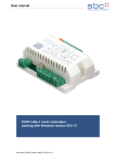
3 Product Description Switch: This device is designed to switch any kind of 230 V mains connected electrical load (resistive, inductive, reactive). The maximum electrical load is defined in the technical product spec. Dimmer: voltage checker. Protect your installation from re-switching. An assembly in built-in sockets is possible. As a result of the compact design, the wireless switch/dimmer/sunblind control can be fastened to canopies (depth min. 30 mm), into sunblinds and suspended ceilings, etc. For facilitating this purpose, the clipped-on switch or base plate may be removed. With the help of a flush-mounted product, an existing switch installation can be enhanced to a wireless-capable one. The wireless Flush-Mountable including support ring and the radio-rocker replaces the existing switch. It can also be manually switched as before, however, it can also be alternatively remote-controlled by means of a controller (remote control or wall switch). This device is designed to dim attached lights. Usage is restricted to incandescent light, high voltage Halogen lamps and any low voltage and Compact Fluorescent Lights (CFL) with resistive or inductive load). The dimmer can’t dim any reactive load, typically for certain switching power supplies or CFLs. Please make sure the right load is connected to the dimmer before operating. Connecting a reactive load may destroy both the load and the dimmer. The maximum electrical load is defined in the technical product spec. Sun blind Control: The device is designed to control single or double motor sunblinds, shutters or electrical gates. The controller turns on a 230 V supply or any other voltage supply to operate the motor and turns off the supply automatically after 1 minute in order to protect the motor. It is possible to adjust the operation time. The maximum electrical load is defined in the technical product spec. Note: The use of Flush-Mountables with equipment that does not comply with the technical standards can cause malfunctioning or damage connected equipments or flush mounted products. 4 Installation The build-in can be controlled both by using clipped-on rockers, as well as wireless wall switch or remote control. The assembly must take place in a voltage-free state by an authorized electrical technician. Turn off the power supply prior to the mounting and confirm the absence of voltage with a 2-pin 5 Wireless Functions – Z-‐Wave 5.1 Z-‐Wave Network Inclusion In order to use the device by a controller the device needs to be included into a Z-Wave network. Only device that are part of the same network can send commands to the device. 2