1
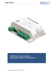
1. Follow the instructions on your Z-Wave Primary or Inclusion Controller to include (add) a Z-Wave device 2. Press Up or Down button three times during 1.5 seconds 3. The LED will become green for 3 seconds and then turn off 4. Your device is ready to work! 5.2 Z-‐Wave Network Exclusion ´ In order to remove the device from a Z-Wave network the following steps have to be performed. 1. Follow the instructions on your Z-Wave Primary or Inclusion Controller to exclude (remove) a Z-Wave device 2. Press Up or Down button three times during 1.5 seconds 3. The LED will begin to blink with red and green continuously. 4. Note! All configurations and associations stored in the device are deleted during Exclusion process 5. Your device can now be removed physically! Attention: Removing the device from the network means that it is turned back into factory default status. 5.3 Z-‐Wave Associations The Flush-Mountable supports single and double paddle click to control other Z-Wave devices. The relationship between a controller paddle click and an action on a different Z-Wave device is called association. If there are different buttons or different ways to operate a button this may result in different actions. Devices that receive the same command from such an action are referred to as association groups. Refer to your Z-Wave Controller instructions to add devices in these association groups. A PC gateway/controller gives you the most comfortable and powerful way to configure your device. Association groups: 2. Double click or click-hold control devices in group No 2 3. Devices in Association group No 3 are informed about all device switch state changes. All groups support up to 8 nodes and 8 (node, channel) pairs. 5.4 Z-‐Wave Configuration Z-Wave products are supposed to work out of the box after inclusion, however certain configuration can adapt the function better to user needs or unlock further enhanced features. Note: Configuration parameters 1…3 and 10…15 are similar for all three devices, switches don’t support configuration #5-#9, dimmers don’t support configurations #8-#9. LED mode (parameter No 1, size 1 byte) Set LED indication mode Values: 0 Disabled 1 Show switch state / when in motion or inactive (for blinds) 2 Night mode (inverted switch state) 3 Operated by Indicator Command Class (default) 4 Show if not closed (for blinds only) Automatically switch off after (parameter No 2, size 2 bytes) If not zero, automatically switch off/close blind after a user defined time Values: 0 1 – 65535 Disabled (default) Switch off 7close blind after X second What to do on RF off command (parameter No 3, size 1 byte) 1. Single click or hold control devices in Association group No 1 3