1
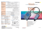
Yokogawa’s, 701928, 701929, 701930, 701931, 701932, and 701933 current probes make it easy
to observe current waveforms on an oscilloscope. Depending on your signal’s bandwidth and
maximum current, you can choose the right current probe for your measurement.
701932
701930
DC to 100 MHz/30 A
NEW
Output voltage rate*
Amplitude accuracy*
0.1 V/A
0 to 30 Arms: ±1% of rdg ±1 mV
To 50 Apeak: ±2% of rdg
(DC, and 45 to 66 Hz)
Noise*
Equivalent to 2.5 mArms or less (for 20 MHz band measuring
instrument)
Input impedance
Typical characteristic shown in figure 3
Temperature coefficient for sensitivity* ±2% or less
(within a range of 0 to 40°C when inputting 50 Hz, 30 Arms)
Maximum rated power
5.6 VA (Within maximum continuous input range)
Rated supply voltage
±12 V ±0.5 V (701933 only)
Operating temperature and humidity range 0 to 40°C, 80% RH or less (no condensation)
Storage temperature and humidity range -10 to 50°C, 80% RH or less (no condensation)
Effect of external magnetic field
Equivalent to a maximum of 20 mA (in a DC or 60 Hz, 400 A/m
magnetic field)
Maximum permitted circuit voltage
300 V CAT (insulated conductor)
Maximum diameter of measured conductor Ø5 mm
Cable length
Sensor cable: approx. 1.5 m (BNC terminal),
Power supply cable: approx. 1 m
External dimensions
Sensor (701929, 701933 common)
: approx. 175 (W) 18 (H) 40 (D) mm
Terminator (701933) : approx. 27 (W) 55 (H) 18 (D) mm
Terminator (701929) : approx. 29 (W) 80 (H) 24 (D) mm
Weight
701933: Approx. 230 g
701929: Approx. 190 g
Accessories
Instruction manual, soft case (701933), carring case (701929)
* In conjuction with a waveform measuring instrument with an input impedance of 1 MΩ ±1%
Standards Compliance
Safety
EN 61010-2-032:2002
Overvoltage category 1(anticipated transient overvoltage 1500 V),
Pollution degree 2
EN 61326:1997+A1:1998+A2:2001
EMC
Output voltage rate*
Amplitude accuracy*
0.1 V/A
0 to 30 Arms: ±1% of rdg ±1 mV
To 50 Apeak: ±2% of rdg
(DC, and 45 to 66 Hz)
Noise*
Equivalent to 2.5 mArms or less (for 20 MHz band measuring
instrument)
Input impedance
Typical Characteristic shown in figure 6
Temperature coefficient for sensitivity* ±2% or less
(within a range of 0 to 40°C when inputting 50 Hz, 30 Arms)
Maximum rated power
5.3 VA (Within maximum continuous input range)
Rated supply voltage
±12 V±0.5 V (701932 only)
Operating temperature and humidity range 0 to 40°C, 80% RH or less (no condensation)
Storage temperature and humidity range -10 to 50°C, 80% RH or less (no condensation)
Effect of external magnetic field
Equivalent to a maximum of 5 mA (in a DC or 60 Hz, 400 A/m
magnetic field)
Maximum permitted circuit voltage
300 V CAT1(insulated conductor)
Maximum diameter of measured conductor Ø5 mm
Cable length
Sensor cable: approx. 1.5 m (BNC terminal),
Power supply cable: approx. 1 m
External dimensions
Sensor (701928, 701932 common)
: approx. 175 (W) 18 (H) 40 (D) mm
Terminator (701932) : approx. 27 (W) 55 (H) 18 (D) mm
Terminator (701928) : approx. 29 (W) 80 (H) 24 (D) mm
Weight
701932: Approx. 240 g
701928: Approx. 190 g
Accessories
Instruction manual, carrying case (701932 and 701928)
* In conjuction with a waveform measuring instrument with an input impedance of 1 MΩ ±1%
EMC
0.01 V/A
0 to 150 Arms: ±1% of rdg ±1 mV
To 300 Apeak: ±2% of rdg
(DC, and 45 to 66 Hz)
Noise*
Equivalent to 25 mArms or less (for 20 MHz band measuring
instrument)
Input impedance
Typical characteristic shown in figure 9
Temperature coefficient for sensitivity* ±2% or less
(within a range of 0 to 40°C when inputting 50 Hz, 150 Arms)
Maximum rated power
5.5 VA(Within maximum continuous input range)
Rated supply voltage
±12 V±1 V
Operating temperature and humidity range 0 to 40°C, 80% RH or less (no condensation)
Storage temperature and humidity range -10 to 50°C, 80% RH or less (no condensation)
Effect of external magnetic field
Equivalent to a maximum of 150 mA (in a DC or 60 Hz, 400 A/m
magnetic field)
Maximum permitted circuit voltage
600 V CAT2(insulated conductor), 300 V CAT3(insulated
conductor)
Maximum diameter of measured conductor Ø20 mm
Cable length
Sensor cable: approx. 2 m (BNC terminal),
Power supply cable: approx. 1 m
External dimensions
Sensor: approx. 176 (W) 69 (H) 27 (D) mm
Terminator: approx. 27 (W) 55 (H) 18 (D) mm
Weight
Approx. 500 g
Accessories
Instruction manual, carrying case
* In conjuction with a waveform measuring instrument with an input impedance of 1 MΩ ±1%
-30
-40
-50
-30
-40
-50
100
10k
1M
1
100
10k
1M
20
15
10
5
1k
10k
100k
1M
10M
25
20
15
10
5
100M
10
100
1k
10k
1
100m
10m
1m
100k
Frequency [Hz]
Fig 3. Input impedance (typical)
1M
10M
100k
1M
10M
100M
1M
10M
-50
-60
-70
-80
100
100M
10k
100k
1M
10M
100k
1M
100M
Fig.10 Frequency characteristics (typical)
1000
100
50
100
10
10
100
1k
10k
100k
1M
10
10M
Frequency [Hz]
100
1k
10k
10M
Frequency [Hz]
Fig.11 Current derating VS. frequency
Fig.8 Current derating VS. frequency
100m
1
100m
10m
1m
100
1k
Frequency [Hz]
150
0
100M
Input impedance [Ω]
1
Input impedance [Ω]
10
10k
100k
Fig.5 Current derating VS. frequency
10
1k
10k
Frequency [Hz]
Fig.2 Current derating VS. frequency
-40
200
30
Frequency [Hz]
100
-70
Fig.7 Frequency characteristics (typical)
Maximum input current [A]
Maximum input current [A]
25
EMC
Frequency [Hz]
35
30
100
-60
1k
Fig.4 Frequency characteristics (typical)
35
10
-50
100M
EN 61010-2-032:2002
Overvoltage category 2, 3 (anticipated transient overvoltage
4000 V), Pollution degree 2
EN 61326-1:1997+A1:1998+A2:2001
-30
-40
Frequency [Hz]
Fig.1 Frequency characteristics (typical)
0.01 V/A
0 to 500 Arms: ±1% of rdg ±5 mV
To 700 Apeak: ±2% of rdg
(DC, and 45 to 66 Hz)
Noise*
Equivalent to 25 mArms or less (for 20 MHz band measuring
instrument)
Input impedance
Typical characteristic shown in figure 12
Temperature coefficient for sensitivity* ±2% or less
(within a range of 0 to 40°C when inputting 50 Hz, 500 Arms)
Maximum rated power
7.2 VA (Within maximum continuous input range)
Rated supply voltage
±12 V±0.5 V
Operating temperature and humidity range 0 to 40°C, 80% RH or less (no condensation)
Storage temperature and humidity range -10 to 50°C, 80% RH or less (no condensation)
Effect of external magnetic field
Equivalent to a maximum of 800 mA (in a DC or 60 Hz, 400 A/m
magnetic field)
Maximum permitted circuit voltage
600 V CAT2(insulated conductor), 300 V CAT3 (insulated
conductor)
Maximum diameter of measured conductor Ø20 mm
Cable length
Sensor cable: approx. 2 m (BNC terminal),
Power supply cable: approx. 1 m
External dimensions
Sensor: approx. 176 (W) 69 (H) 27 (D) mm
Terminator: approx. 27 (W) 55 (H) 18 (D) mm
Weight
Approx. 520 g
Accessories
Instruction manual, carrying case
* In conjuction with a waveform measuring instrument with an input impedance of 1 MΩ ±1%
-80
100M
Frequency [Hz]
Ambient temperature: 23±3°C, after power-on following 30 minutes
warmup period
DC to 2 MHz (-3dB) (typical characteristics shown in figure 10)
175 ns or less
500 Arms (derating according to frequency shown in figure 11)
700 Apeak (discontinuous)
Output voltage rate*
Amplitude accuracy*
-30
-20
-60
1
Bandwidth*
Rise time*
Maximum continuous input range
Maximum peak current value
Standards Compliance
Safety
EN 61010-2-032:2002
Overvoltage category 2, 3(anticipated transient overvoltage
4000 V), Pollution degree 2
EN 61326-1:1997+A1:1998+A2:2001
EMC
Amplitude [dB, 0dB=1 V]
Amplitude [dB, 0dB=1 V]
Amplitude [dB, 0dB=1 V]
EN 61010-2-032:2002
Overvoltage category 1(anticipated transient overvoltage 1500 V),
Pollution degree 2
EN61326:1997+A1:1998+A2:2001
701931 Specifications
Ambient temperature: 23±3°C, after power-on following 30 minutes
warmup period
DC to 10 MHz (-3dB) (typical characteristics shown in figure 7)
35 ns or less
150 Arms (derating according to frequency shown in figure 8)
300 Apeak (discontinuous)
500 Apeak at pulse width of 30 µs or less
Output voltage rate*
Amplitude accuracy*
Standards Compliance
Safety
Standards Compliance
Safety
-60
Input impedance [Ω]
Bandwidth*
Rise time*
Maximum continuous input range
Maximum peak current value
-10
-20
Maximum input current [A]
701930 Specifications
Ambient temperature: 23±3°C, after power-on following 30 minutes
warmup period
DC to 100 MHz (-3dB) (typical characteristics shown in figure 4)
3.5 ns or less
30 Arms (derating according to frequency shown in figure 5)
50 Apeak (discontinuous)
Bandwidth*
Rise time*
Maximum continuous input range
Maximum peak current value
-10
2
DC to 100 MHz/30 A
DL9000 probe I/F
701932/701928 Specifications
Ambient temperature: 23±3°C, after power-on following 30 minutes
warmup period
DC to 50 MHz (-3dB) (typical characteristics shown in figure 1)
7 ns or less
30 Arms (derating according to frequency shown in figure 2)
50 Apeak (discontinuous)
Bandwidth*
Rise time*
Maximum continuous input range
Maximum peak current value
701928
DC to 50 MHz/30 A
DL9000 probe I/F
701933/701929 Specifications
DC to 2 MHz/500 A
NEW
Maximum input current [A]
701929
701931
DC to 10 MHz/150 A
Amplitude [dB, 0dB=1 V]
DC to 50 MHz/30 A
Input impedance [Ω]
701933
0.1
0.01
0.001
1k
10k
100k
1M
10M
100M
1m
10k
100k
1M
Frequency [Hz]
Frequency [Hz]
Fig 6. Input impedance (typical)
10m
Fig 9. Input impedance (typical)
10M
10k
100k
1M
Frequency [Hz]
Fig 12. Input impedance (typical)
3