1
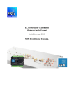
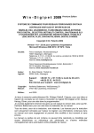
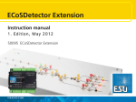
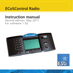
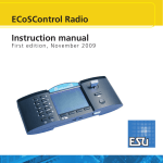
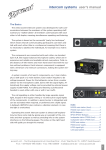
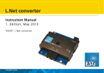
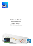
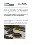
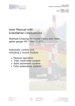
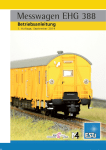
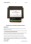
Mobile Control II
User manual
1. Edition, November 2015
1
Content
Inhalt
1. Declaration of conformity......................................3
11. Controlling locomotives and consists.................13
2. WEEE declaration..................................................3
11.1. Selecting a locomotive.......................................13
11.1.1. Searching locomotives.....................................13
11.2. Running locomotives . .......................................13
11.2.1. Speed & Direction...........................................14
11.2.2. Functions........................................................14
11.2.3. Changing locomotives.....................................14
11.2.3.1. Quick selection.............................................14
11.3. Blocked locomotive............................................15
11.4. Edit locomotive..................................................15
11.4.1. Locomotive name............................................15
11.4.2. Icon................................................................15
11.4.3. Data format....................................................16
11.4.4. Address...........................................................16
11.4.5. Function button icons.....................................16
11.5. Setting up a new locomotive..............................16
11.5. Registering RailComPlus or M4 locomotives.......16
3. Important Note – Please read this first...................4
4. Content of package..............................................4
5. Introduction – Features of Mobile Control.............4
5.1. Android 4.1 operating system................................4
5.2. Wireless LAN (Wi-Fi) radio transmission..................5
5.3. Remote control handset.........................................5
5.4. Controlling locomotives..........................................5
5.5. Accessories and routes...........................................5
6. Control elements .................................................5
6.1. WLAN Access point................................................6
7. Unpacking & connecting ......................................6
7.1. Battery ..................................................................6
7.2. Lanyard..................................................................6
7.3. Operating conditions..............................................6
7.4. Types of radio connections.....................................6
7.4.1. Independent isolated operation...........................6
7.4.1.1 Connecting the Access Point ............................7
7.4.2. Connection to the home network.......................7
12. Accessories & routes..........................................17
8. Settings on the ECoS.............................................7
13. Configuration menu.........................................19
8.1. Defining the host name..........................................7
8.2. Independent isolated operation..............................8
8.2.1. IP settings...........................................................8
8.2.2. Access Point network name and password..........8
8.3. Settings for the home network...............................9
8.4. Activating “locomotive take over”.........................9
9. Switching on the Mobile Control II........................9
9.1. Handling Android...................................................9
9.1.1. Main screen......................................................10
9.1.1.1. Home button.................................................10
9.1.1.2. Return button................................................10
9.1.1.3. Menu button.................................................10
9.2. Set-up..................................................................10
9.2.1. Language..........................................................10
9.2.2. Display .............................................................10
9.2.2.1. Passive state...................................................10
9.2.2.1. Brightness......................................................10
9.3. Programs..............................................................10
9.3.1. Google Play Store..............................................10
9.4. Connecting to WLAN...........................................10
9.5. Starting App and selecting the command station.12
9.5.1. Demo mode......................................................12
10. The main screen................................................12
10.1. Main menu........................................................12
2
12.1. Signal-box mode (Route control)........................17
12.2. New signal-box .................................................17
12.2.1. Downloading from the ECoS...........................17
12.2.2. Placing accessories..........................................18
12.3. Switching accessories.........................................18
12.4. Select signal-box................................................18
13.1. Main controls.....................................................19
13.2. Stop button delay..............................................19
13.3. Trace speed........................................................19
13.4. Compact function view......................................19
13.5. Keep screen on..................................................19
13.6. Displaying the version number...........................19
13.7 Assignment of buttons........................................19
15. Software update ..............................................20
15.1. Google Play Store...............................................20
15.2. PC Software.......................................................20
16. ESU Support.....................................................21
16.1. Registration........................................................21
16.2. Forum................................................................21
16.3. Technical hotline................................................21
17. Appendix..........................................................22
17.1 Technical data.....................................................22
17.2. Throttle knob API...............................................22
18. Warranty certificate...........................................23
18.1. Warranty conditions...........................................23
18.2. Extent of warranty / exclusions...........................23
Declaration of conformity
1. Declaration of conformity
2. WEEE declaration
We, ESU electronic solutions ulm GmbH & Co KG, Edisonallee 29, D-89231
Neu-Ulm, Germany, declare in sole responsibility the product
50113 ESU Mobile Control II Set, 50114 ESU Mobile Control II
to which this declaration refers, complies with the following standards:
EN 71 1-3 : 1988 / 6 : 1994 – EN 50088 : 1996 – EN 55014, part 1 +
part 2 : 1993
EN 61000-3-2 : 1995 – EN 60742 : 1995 – EN 61558-2-7 : 1998
According to the regulations of the directive
88 / 378 / EWG – 89 / 336 / EWG – 73 / 23 / EWG
ETSI EN300 328:2007-04
The Mobile Control II bears the CE mark.
Disposal of obsolete electrical and electronic equipment (as practised in the
European Union and other European countries with dedicated collection systems).
This mark on the product, the packaging or the relevant documentation indicates that this product must not be treated like household waste. Instead
this product should be disposed of at a suitable collection point for recycling
of electrical and electronic appliances. Thus you contribute to avoid negative
impact on the environment and people’s health that could
be caused by inappropriate disposal. Recycling of materials
contributes to preserve our natural resources. For more information regarding recycling of this product, please contact
your local administration, your waste collection service or the
dealer / shop where you purchased this product.
Batteries do not belong in household trash!
Bitte entsorgen Sie leere, verbrauchte Batterien nicht in den Hausmüll: Bringen Sie sie zu einer Sammelstelle in Ihrer Gemeinde oder im Fachhandel. Eine
umweltschonende Entsorgung wird dadurch sichergestellt.
Copyright 1998 - 2015 by ESU electronic solutions ulm GmbH & Co KG. Mistakes, modifications resulting in technical advancement, availability and all other rights reserved. Electrical and mechanical characteristics, dimensions and sketches are subject to change without prior notice. ESU may not be held responsible for any damage or consequential loss or
damage caused by inappropriate use of the product, abnormal operating conditions, unauthorized modifications to the product, etc. Not suitable for children under 14 years of age.
Inappropriate use may result in injury due to sharp points and edges.
Märklin® and mfx® are registered trademarks of Gebr. Märklin® und Cie. GmbH, Göppingen, Germany. RailCom® and RailComPlus® are registered trademarks of Lenz Elektronik
GmbH, Giessen. Android® und PlayStore® are registered trademarks of Google Inc. All other trademarks are the property of the respective legal owners.
According to its policy ESU electronic solutions ulm GmbH & Co KG continues to develop its products further. Therefore ESU reserves the right to implement changes and improvements to any of the products listed in the ESU documentation without prior notice.
Duplication and/or reproduction of this documentation in any form or shape require prior written consent by ESU.
3
Introduction - Features of Mobile Control
3. Important Note – Please read this first
Congratulations to your purchase of a Mobile Control II. The Mobile Control
II offers you the opportunity to run your locos remotely (wireless) in conjunction with the ECoS ESU command station as well as the Märklin® central
station Reloaded (with ESU update 3.0.0 and higher). Due to its ergonomically designed motorised throttle and the Android operating system makes
running your model trains more comfortable and easier than ever before.
This manual offers you a step-by-step insight into the available options of the
Mobile Control II.
•The Mobile Control handset is designed solely for the use with model
trains. Never leave the Mobile Control unit operating in conjunction with
the ECoS without supervision and never use it for controlling devices that
transport people.
•The Mobile Control may only be operated with the devices described in
this manual. Any other use than described in this manual is not permitted.
•The Mobile Control works with WIFI technology in the especially reserved 2.4 GHz frequency band. Disturbance by other devices are therefore
highly unlikely.
•Do not drop your Mobile Control or sit on it and do not shake it or expose it to mechanical impact. Such rough handling may cause damage to
the components of the device.
•Do not expose the components of the Mobile Control to humidity or
direct sunlight.
•Do not apply any caustic chemicals, cleaning detergents or similar for
cleaning your Mobile Control handset.
•Do not attempt to open the housing of your Mobile Control. Inappropriate handling may cause damage to your Mobile Control.
4. Content of package
Please check the completeness of your Mobile Control immediately after
opening the package.
You should find the following components in the package:
• Mobile Control handset
• USB battery charger cable
• Lanyard
• (This) manual
If you have purchased the set 50113, then you should also have the following:
• Mini Access Point KX-300
• Wall power supply for Mini Access Point
• Network cable RJ45, ca. 30 cm long
4
Figure 1: Contents of Mobile Control Set
5. Introduction – Features of Mobile Control
With Mobile Control you have acquired a system that can accomplish much
more than “just run locos“ in wireless mode. In this chapter we introduce
you to the features of the Mobile Control handset.
5.1. Android 4.1 operating system
Mobile Control is the first model train controller based on the Android operating system (version 4.1). This system, originally developed by Google as an
operating system for smart phones, has advanced to become a universally
useful operating system in recent years, and is now installed in TV sets, washing machines or motor vehicles, amongst others. The beauty of Android
is that you as the user can easily extend the system and add more functions
with the aid of “Apps” (Application Program). You may download and install
these apps directly from the “Google Play Store”.
Due to its touch screen and its well thought out and standardised graphic
user interface, operating Android devices becomes quite easy after a short
while - even for the untrained user.
Since the Android system can easily be adapted to new systems it was an
obvious choice to equip the ESU Mobile Control with this operating system.
Thus you have a contemporary, easy to handle throttle for your model trains
that can be extended at any time by downloading further apps from the
Google Play Store. Such apps do not necessarily have to originate from ESU;
software developers are welcome to write or adapt Apps suitable for the
Mobile Control.
Control elements
5.2. Wireless LAN (Wi-Fi) radio transmission
The radio transmission of the Mobile Control is based on the (Wireless Local
Area Network) standard, which has been standardised many years ago by the
IEEE and which has proven itself over and over. Utilising an open standard offers many advantages for you as a user: Due to the reserved frequency band
with many automatically searched radio channels, disturbances by other
participants in the radio network are eliminated for all practical purposes.
Data transmission in both directions is very quick and reliable assuring a very
short response time of your locomotives virtually without any delay. This also
facilitates that all changes made on the ECoS are transferred to the Mobile
Control and vice versa. Thus all data such as speed of locomotives or turnout
settings are always synchronised between the Mobile Control handset and
the ECoS.
Furthermore it is possible to increase the range by installing commercially
available WLAN repeaters at any time.
Up to 32 Mobile Control handsets may be connected to an ECoS or a Central
Station Reloaded.
5.3. Remote control handset
When you hold the Mobile Control for the first time you will immediately
notice the excellent ergonomic design: you can reach all control elements
single handed and the most important ones even without looking: you keep
looking at the layout and your trains.
This is facilitated by the centrally located, motorised throttle knob with limit
stop, which enables you to delicately adjust the speed of your trains as well
as the direction of travel.
For switching functions simply touch the icons on the touch screen. The
touch screen also serves for easy handling of functions – exactly as you are
used to from your mobile phone. There are two buttons on either side of
the unit, which you may assign to any function you desire; for instance, for
changing the direction or for the most important functions.
6. Control elements
a)
c)
4.
g)
f)
1.
3.
5.4. Controlling locomotives
In the locomotive mode you can observe the most important operating parameters such as the locomotive name, icon, speed as well as the function
status, at a glance. The speed is controlled with the throttle knob. Subject to
the data format one can switch up to 28 functions plus the headlights.
You may assign to and control as many locomotives as you wish with each
handset. Each throttle can control different locomotives. Taking over a locomotive from another handset (“stealing a loco”) can be permitted if so
desired.
5.5. Accessories and routes
Switching accessories and routes is no big deal for the Mobile Control: One
can define any number of signal-boxes, on which you may place and control
accessories and routes according to your preference. If so desired, the signalboxes can be taken directly from the ECoS or can be designed differently. All
icons and signal aspects as set on the ECoS will be directly transferred to the
Mobile Control.
2.
e)
b)
Figure 2: Mobile Control with control elements
a)Power button: A long push of the power button turns the Mobile Control
on or off. Starting up the Android system takes about two minutes. A short
press of the power button switches the already active device into standby
mode. If the device is active but the touch screen is dark, a short press of
the power button turns on the display.
b)USB charger socket: This socket serves for connecting a battery charger
respectively for connecting the device to a PC.
c)Motorised throttle knob: The throttle knob with limit stop allows you to
set the desired speed. Turning it anti-clockwise to the limit stop results in a
change of direction. The throttle knob is motorised and follows the required speed.
5
Unpacking & connecting
d)Touch buttons: There are four system buttons on the touch screen
a.Menu: Calling up App dependent menus.
b.Home: Pressing the Home button changes the display to the Android start
screen at any time.
c.Back: This button causes a step back in the menus or Apps.
d.Emergency Stop: Pressing this button while the Mobile Control App is active (!), turns the DC current on or off. One LED (red/green) signals the track
status.
e)Jack bush: This 3.5mm jack bush serves for connecting a headset (Nokia or
Samsung compatible). Besides two stereo speakers one can also connect a
microphone.
f) Charging gauge: displays the battery status.
g)WLAN display: Shows the WLAN signal strength.
6.1. WLAN Access point
We recommend to fully charging the batteries prior to initial use
and not turning on the device before the batteries are fully charged.
During charging the Mobile Control may be used, however, subject
to the type of charger the touch screen may not work reliably or
not at all.
Alternatively to a separate charger one may also use the USB socket of the
Mini Access Point for charging the batteries.
The battery can be replaced by a new one at the end of its life. Suitable batteries with the part number 50113.SP.01 are available from ESU.
7.2. Lanyard
The supplied lanyard can be fed into the eye at the bottom of the Mobile Control handset. We recommend always carrying the Mobile Control by
putting the lanyard around your neck. Thus it will never inadvertently fall to
the floor.
a) Ethernet socket: For connecting
the Mobile Control to the ECoS.
c) Mains connection socket: For connecting the mains adapter supplied with
the set.
Figure 4: Section of the eye with threaded lanyard
b)USB charger socket: For
recharging the batteries
of the Mobile Control.
Figure 3: WLAN Access Point
7. Unpacking & connecting
7.1. Battery
The Mobile Control is powered by an integral Lithium Polymer rechargeable
battery generally good for 3 to 5 hours operating time. The charger cable is
plugged into the micro USB socket at the bottom of the device. Connect this
socket with the supplied USB charger cable with any USB charger or directly
with the USB port of your computer. You may use any of the commercially
available USB chargers, as you know them, for instance, from your mobile
phone. Charging to a full load takes about two to three hours.
6
7.3. Operating conditions
In order to operate the Mobile Control successfully with your ECoS or Central
Station Reloaded, the internal software status of the ECoS or the Central
Station Reloaded must be version 4.1.0 or higher. Possibly you may have to
first update the software of your command station. You will find the relevant
information regarding firmware updates in the manual of your command
station.
If the firmware of your command station is outdated, then the
Mobile Control will not detect, respectively recognise the command station and will not allow the device to connect.
7.4. Types of radio connections
First you must decide how you want to establish the wireless connection between your ECoS and the handset. There are two basic types of connection
supported by the Mobile Control. Both have their advantages and disadvantages. Subject to the type of connection you choose, you must configure
your ECoS respectively your Mobile Control accordingly.
7.4.1. Independent isolated operation
In this scenario the combination of ECoS and Mobile Control operate independent of any network components in your household. You will need a
WLAN access point (generally you would use the Mini Access point KX-300
supplied with the set 50113), which has to be connected directly to the network socket of your ECoS. The Mini Access Point generates its own WLAN
network to which only the Mobile Control will be linked. All settings such as
passwords, network name etc. will be entered directly on the touch screen
Connections
of your ECoS. There is no need for a PC resp. no connecting point for it is
provided.
7.4.2. Connection to the home network
In this scenario you utilise the existing WLAN network of your household in
order to link the Mobile Control with your ECoS. For this purpose you need a
WLAN router (e.g.: AVM®, Fritzbox®) a well as a network cable for connecting the ECoS directly with the WLAN router.
Figure 5: Isolated operation
This type of connection is suitable for layouts that should be operated completely independently. This may be the case with exhibition layouts, amongst
others, that have to be set up and dismantled frequently. Neither the ECoS
nor the Mobile Control II gets access to the internet. In order to update the
devices they have to be temporarily connected to a PC.
This operating mode is recommended for users who have little
experience in setting up home networks and who have no need
for an internet connection.
7.4.1.1 Connecting the Access Point
In order to assure that the isolated operation works properly, you must first
connect the Mini Access Point with the supplied network cable to your ECoS.
Of course, you also need a mains power outlet for the power supply.
Figure 7: Home network
In this scenario the data travel first from the Mobile Control via the wireless
transmission to the WLAN router and from there via the network cable to the
ECoS. The administration of the IP addresses, WLAN passwords and network
name is taken care of by the WLAN router. ECoS and Mobile Control get their
IP addresses automatically from the WLAN router.
Both, the ECoS and the Mobile Control are connected to the internet. The
advantage is that the Mobile Control will get available updates directly from
the Google PlayStore and will automatically install them.
We recommend this type of connection, if you are familiar with
the configuration of a home network respectively, if it is possible to connect the ECoS with the WLAN router with a cable. If
your ECoS and Mobile Control should also be linked to a control
software on your PC (e.g. WinDigiPet, RailWare, TrainController,
RocRail or others), then this type of connection is also useful.
8. Settings on the ECoS
Ethernet connection
power ECoS
Subject to the type of connection you have chosen and in order to assure
that your Mobile Control can establish a link to your ECoS without problems,
some settings must be done in the ECoS set-up menu.
All pictures in the following figures show an ECoS 50200; however, this information can also be applied to the monochrome
touch screen of the ECoS 50000 respectively the Märklin Central
Station “Reloaded”.
8.1. Defining the host name
power Access Point
Figure 6: Mini Access Point connected to the ECoS
First you should assign a network name to your ECoS. This name will be
shown on the display of your Mobile Control later on. Otherwise you would
have no means to determine with which ECoS your handset has set up the
link, in case there are several ECoS command stations in the same network.
7
Settings
In the next step you must change the name of the Wi-Fi network as well as
the password. Should you not do this; any Mobile Control can connect to
your ECoS, something you certainly do not want to happen.
8.2.2. Access Point network name and password
•Press the “OK & Setup WIFI” button
•Now the ECoS is searching for the Mini Access Point. Please be patient,
because this may take up to 30 seconds.
Figure 8
8.2. Independent isolated operation
If you have decided to employ the independent isolated operating mode,
then you must first connect and switch on the WLAN Access Point as described in section 7.4.1.1. In this operating mode the administration of the
network IP addresses is handled by the ECoS. For this purpose you must
first assign an IP address to the ECoS. Then the internal DHCP server will be
started and subsequently the Access Point configured. And that is how it is
done:
Figure 10
8.2.1. IP settings
Call up the set-up menu on your ECoS and go to the Setup 1 in the IP setup.
Figure 11
Figure 9
•First remove the tick at “Get IP settings from DHCP”, if set.
•Then enter an IP address at “IP address”, for instance: 192.168.94.1
•Enter the value 255.255.255.0 at “Netmask”
•Set the tick at “Spawn DHCP-server“
8
First you see the current settings for the network name and the network
password.
If the desired settings are not displayed after 1 minute at the latest, then exit the dialogue by pressing the “X” button, remove
the power supply from the Access Point, wait about 5 seconds,
re-insert the wall power supply and restart the configuration dialogue.
Settings
•Enter the new network name.
•Enter your preferred password.
•Confirm by
If the password is either too long or too short, or if it contains
invalid characters, then the “Ok” button appears grey. Please correct your entry in this case.
For your information the ECoS will display the data received from the WLAN
router after a few seconds. No change is possible or required.
Depending on the settings of your WLAN router, the settings
displayed on your ECoS may differ. This is quite normal and no
reason for concern.
8.4. Activating “locomotive take over”
If so desired, the ECoS system allows other throttles to take over and control
locomotives. This may be advantageous if you have several handsets but
operate your layout mainly on your own. If you want to activate the “Loco takeover”, simply set a tick at “Allow takeover of locos by other controllers”.
Figure 12
In order to establish a link to your Mobile Control, you will need the newly
established network name and password later on.
Figure 14
8.3. Settings for the home network
If you wish to link your ECoS with your Mobile Control via your home network, then you must first connect your ECoS with a so called RJ45 patch cable to your WLAN router. How to do this is described in chapter 7.4.2. Usually
you will find available network sockets marked with “LAN”. If the connection
is successful, then the “Link” LED on your ECoS will light up.
In this case the administration of the IP address is handled by the WLAN
router. You have to tell your ECoS this fact by setting the tick “Get IP settings
from DHCP”.
9. Switching on the Mobile Control II
Press and hold the power button until an icon appears on the screen. The
very first switch-on may take up to two minutes until Android has started
and updated all system settings. Please consider the following when working
with the mobile Control:
• In order to save energy the display is turned off automatically after one minute of inactivity just like a mobile phone .
•In this case simply press the power button for a short time (less than one
second) in order to activate the device once again.
•Even when the display appears dark, the throttle is still active and consumes energy. The battery will probably be discharged after one day in
“Stand by” and the device will shut down automatically.
•At the end of an operating session we recommend to shut down the Mobile Control by pressing and holding the power button (while the display is
active) until the switch-off menu appears. If you now select “Turning-off”
and confirm the query, then the device will shut down permanently.
9.1. Handling Android
Although handling Android has been designed very intuitively and since the
Mobile Control II is to be handled, by and large, like a mobile phone we think
a few basic tips are in order.
Figure 13
9
Set-up
9.1.1. Main screen
9.2.1. Language
You will see two pictograms on the start-up screen:
a)Symbol for starting the actual mobile control App
b)Icon for calling up the Android set-up menus
c)Icon for viewing all installed Apps
You may change the system language at any time. Currently the
Mobile Control App developed
by ESU only supports German
and English.
9.2.2. Display
There are two important settings
within the display settings.
9.2.2.1. Passive state
Here you can adjust after how
many minutes of inactivity the
screen of the Mobile Control is
turned off. The higher this value,
the more energy is consumed.
9.2.2.1. Brightness
Here you can adjust the brightness of the display. Preferably
choose a rather dark setting in
order to extend the operating
time before you have to recharge the batteries.
a)
b)
c)
Figure 15
You may start the actual Mobile Control software by touching the icon a).
9.1.1.1. Home button
If you want to return to the start-up screen, simply press the home button in
any menu and at any time.
9.1.1.2. Return button
The return button always leads you back to the previous menu.
9.1.1.3. Menu button
In many programs there is an option to access extended properties by pressing the menu button.
9.2. Set-up
It pays off to first have a look at the set-up menu. There you will find several
settings, which you may want to adjust right at the start.
The brighter the display, the more heat is generated in the device.
This is quite normal and no reason for concern.
9.3. Programs
Here you can see which programs have been installed. However, what really
matters, is the Google Play Store.
9.3.1. Google Play Store
The Google Play Store is the place where you may obtain new
Apps and install them on your device. To make sure that this will
work as intended, you must link your device with your Google
account or, if you do not have an account yet, you must establish a new account.
Please note that we have no commercial or any other type of link
with Google at all. The data submitted when opening an account
are not sent to ESU and we are not in a position to obtain such
data.
All Apps and programs should be easily installed on the Mobile
Control unit. Of course, we cannot provide a guarantee for the
proper working of Apps not supplied by ESU.
The memory of the Mobile Control is limited. Please bear this in
mind when installing programs.
9.4. Connecting to WLAN
After setting up the device you must establish a link to WLAN. This may either be your home network or the WLAN signal generated by the Mini Access
Point; also refer to the relevant information in chapter 7.4.
10
Connecting to WLAN
Ex works, the ESU Mini Access Point responds to the name “ESUWIFI” with the password “123456789”. If the Mobile Control
finds this network, it will automatically attempt to establish a connection. In this case you may skip the following steps.
•Press “Connect”. If the password has been entered correctly, the connection will be established after a short while.
•Select the first menu item “Wi-Fi” in the Android set-up. Make sure that
the slide control is set to “On”.
•Select the desired network from the list of available Wi-Fi networks by
touching its name.
•Enter the password exactly like you have defined it in chapter 8.2.2. Note:
You may display the characters of the password, if so desired. Scroll down
until the option “Show password” appears. Thus any erroneous entries are
avoided.
The quality of the signal link is permanently displayed in the status
bar at the top. The longer the bar, the stronger and more reliable
is the connection.
11
Main Screen
9.5. Starting App and selecting the command station
After the WLAN connection to the ECoS has been established successfully,
you may start the actual Mobile Control II control App. This is done by pressing the MC II icon on the main screen.
First one must select the command station to which the
Mobile Control should be connected. This cannot be done automatically, because there may
be several command stations in
a network. Therefore a list with
the available command stations
is displayed:
Select the command station to
which you want to establish a
connection. Normally only one
ECoS should be shown. For better orientation the software version as well as the IP address of
the command station are being
displayed in addition to the host
name of the command station
(also refer to chapter 8.1).
9.5.1. Demo mode
The App memorises which command station you have chosen.
During the next start, establishing a link will give priority to
the most recently employed
command station. Should this
be unsuccessful, then the list of
all available command stations will be displayed.
If there is no command station in the network, then you may select the demo
mode in the context menu. You can test the device with the aid of this demo
mode.
12
10. The main screen
Finally the main screen of the Mobil Control will be displayed. All main functions are controlled from this screen.
d)
a)
c)
b)
a)Toggling between locomotive control and accessory control panels (signal-box)
b)“+” Adding locomotives or accessory control panels to the quick access list
c)“-“ Deleting locomotives or accessory control panels from the quick access list
d)Displaying the main menu
10.1. Main menu
Locomotives and consists
The main menu is displayed as soon as you touch the appropriate button.
You may also toggle between the basic functions “Drive” or “Switch” in the
main menu. In addition you can call up two lists:
•You can display all locomotives stored in the ECoS in the “Locomotive
list“.
•You can display and select all available switching panels in the “Accessory
control panel list”.
11.1.1. Searching locomotives
If there are many locomotives in the list, one can accelerate the search by
pressing the magnifier icon in order to call up the search.
•Touch parts of the name or (if known) the address of the desired locomotive.
•The “hits” will be shown even while you are typing.
•With “Read / Write CVs“ you can access the programming track of the
ECoS.
•With “DCC address” you can read out and change the address of a locomotive on the programming track.
•The “Settings” button enables you to access the configuration menu. Find
more information about this in chapter 13.
You may exit the main menu by pressing the touch button “Return” at the
bottom right at any time.
11. Controlling locomotives and consists
The most important function of the Mobile Control is controlling locomotives
and consists. All locomotives stored in the ECoS may be called up.
11.1. Selecting a locomotive
First one must call up the locomotive that shall be operated.
•Press the “+” symbol in order to enter the locomotive list.
•Select the desired locomotive by touching the icon.
11.2. Running locomotives
You have direct access to a locomtive as soon as it has been selected.
a)
b)
g)
c)
d)
e)
j)
f)
i)
h)
13
Functions
a)List of all locomotives already called up (“Quick access list”) with plain text
name of the locomotive.
b)Status of the functions of the currently controlled locomotive. The current
status is displayed for each function (On or Off).
c)Locomotive icon
d)Direction “Forward”
e)Direction “Back up”
f)Locomotive address
g)Speed step setting
h)Speed steps: the maximum number of speed steps of the locomotive (subject to data format and protocol)
i)Currently set speed step
j)Speed step indicator
If a locomotive has more functions than can be displayed on the screen you
can scroll by wiping from the bottom upwards (directly in the block with the
function icons), giving you an overview over all 28 functions.
11.2.3. Changing locomotives
If you wish to control another (additional) locomotive simply press the “+”
button in order to access the locomotive choice list. Then select another locomotive as described in chapter 11.1. All locomotives are now shown in the
quick access list. If you wish to call up the next locomotive and run it, then
simply wipe to the left or right within the field of the function buttons.
11.2.1. Speed & Direction
•Turn the throttle knob to the right and the locomotive will start moving.
The speed step indicator will display the current speed immediately while
the speed step is shown for accurate control.
•Turn the throttle knob to the left beyond Zero until you hear a “Click”,
then the direction of travel will be changed. The throttle knob is motorised. If you turn the throttle knob beyond Zero for changing the direction,
simply let go of it afterwards. It will automatically return to the Zero position.
11.2.2. Functions
There is an icon for each function button describing the function more closely. In addition, a number located at the bottom right indicates the indenture
number; starting with 0 at the top left (for the lighting button F0). In order
to easier recognize the type of function, the icons of the individual function
groups (mainly physical functions, logical functions and sound functions) are
displayed in different colours.
•Press the icon for turning on or off a function.
•Depending on whether a function is set as a continuous or a momentary
function, the function may remain only active as long as you touch the
icon with your finger.
The currently controlled locomotive (class 261 in this example) is displayed
bright and underlined. Every time you change to another locomotive the
throttle knob will move to the appropriate position to match the locomotive
speed setting.
11.2.3.1. Quick selection
With the method described you may easily
select the next locomotive in the quick access
list by wiping left or right. However, you may
also select the desired locomotive directly.
•Touch and hold the name of the current
locomotive in the quick access list until the
quick selection menu appears.
•Choose the desired locomotive directly.
14
Edit locomotives
In case the locomotive is blocked, then the function is not
available.
11.3. Blocked locomotive
When you call up a locomotive it may happen that it may be displayed, but
you cannot control it. In this case the text “Display only” will appear below
the locomotive picture instead of the speed indicator. This means that this
locomotive is currently controlled by another throttle.
After selecting the function, the “Edit locomotive” screen will open.
Confirm
changes
Locomotive
name
Locomotive
image
Address
Function
buttons
Provided the ECoS has been configured as described in chapter 8.4., you may
take over control of this locomotive by pressing a function button or changing the speed setting. The Mobile Control handheld only attempts to take
control of the locomotive from the ECoS at the time of first access. If this is
possible (and permitted), the “Display only” text will disappear.
11.4. Edit locomotive
If you wish, you may edit the characteristics of a locomotive directly with your
Mobile Control. All changes will also be transferred to the ECoS and other
handsets. First press the menu button at the bottom left and select “Edit
locomotive” from the menu.
Once you have confirmed all changes press the “Finished” button. For saving all changes press the “Return” button at the bottom right of the touch
screen. If you do not wish to save any changes, press the menu button at the
bottom left and select “Disregard changes”.
11.4.1. Locomotive name
Choose a meaningful name for your locomotive. It helps to find it quicker.
11.4.2. Icon
Touching the locomotive icon opens the choice list of all available locomotive
images. The Mobile Control displays all images available on the ECoS. The
icon has no influence on operations; it only serves for a quick visual differentiation of your locomotives. You have a choice between internal (ex works)
images on your ECoS and user defined images.
15
Function button icons
You may define if you only want to display internal images or user defined
ones, or only steam, diesel or electric locomotive images in the context menu
(touch button at the bottom left).
With the help of the locomotive icon the command station recognises if it is a steam, diesel or electric locomotive. This differentiation comes in handy later on when you are searching a specific
locomotive.
11.4.3. Data format
In this choice list you may determine the data format of this specific locomotive. However, the command station will not check if this locomotive actually
supports this protocol. If in doubt, read the relevant passages in the decoder
manual respectively refer to chapter 11.2.3.1 of the ECoS manual.
You cannot change the data format for locomotives that were
detected and registered via M4 respectively RailComPlus.
11.4.4. Address
Here one must enter the current locomotive address. Subject to the data
format employed, the valid address range may be limited. The locomotive
will be controlled with this address on the layout.
If the locomotive has been registered automatically by RailComPlus and you then change the address here, the newly selected
address will be written onto the decoder (programmed) once you
have confirmed this change. In all other instances the address will
not be written onto the decoder but must be programmed manually.
•Select the desired icon from the list for each function. For your orientation
you will find its meaning illustrated next to the icon.
•Decide if the function should be continuous or momentary. Momentary
functions only remain “On” as long as you touch the icon. Continuous
output functions remain on until you touch the icon on the screen once
again.
•If you do not wish to use a particular function button (icon), simply disable
it with the switch at the top right.
A disabled function is not displayed on the “Running locomotives” screen. The other function buttons move up accordingly. If
you want to have a gap, however, then you may achieve this as
shown in chapter 13.4.
11.5. Setting up a new locomotive
When setting up new locomotives manually, the same remarks apply as described for editing locomotives. Please note that one never should assign a
locomotive address twice. M4 locomotives or the ones equipped with RailComPlus cannot be registered manually at all. They will always register automatically.
11.5. Registering RailComPlus or M4 locomotives
Locomotives equipped with an M4 or RailComPlus capable decoder automatically register with the ECoS command station. As soon as you have put
a new locomotive onto the track, it will be automatically detected. It will
immediately be displayed on the main screen of your Mobile Control.
11.4.5. Function button icons
You may assign an icon to each function. One cannot only assign an icon
for each locomotive and for each button, but one can also determine if it is
continuous output or momentary function.
If you wish to run this newly registered locomotive with your hand set, simply
touch “Open”. After a short while this notice disappears automatically.
16
Accessoires and routes
12. Accessories & routes
With the Mobile Control you can also control accessories and routes. The
handling is quite similar to that on the ECoS. Therefore it is advisable to first
read up the chapter 13 in your ECoS manual.
You may set up as many signal-boxes on your Mobile Control, which are
independent of the ones on your ECoS and set up accessories or route icons.
The signal-box will always display the current status of all accessories.
12.2.1. Downloading from the ECoS
If so desired, you may copy a signal box directly from the ECoS to the Mobile
Control handset. This is useful whenever you want to have exactly the same
arrangement of signal-boxes. Let us assume you want to copy the following
signal-box, page No: 1 (please take note of the tabs marked in yellow).
12.1. Signal-box mode (Route control)
• First select the signal-box mode in order to be able to switch accessories and to work with the signal-boxes.
At the beginning there will only be an empty screen. You must set up at least
on signal-box to start with and link some accessories to it.
Figure 16
• Select the “Download” button
• Then select page “1” and signal-box No: “2”
• Press “Download”
12.2. New signal-box
• Select “Create panel” from the context menu
•Enter a name for the panel
17
Placing accessoires
After a few moments the signal-box “Mainstation” on your mobile Control
will look exactly like the one on your ECoS.
12.3. Switching accessories
After successfully configuring the signal-box all accessories can be switched
by touching the appropriate icon.
•The aspect of two-aspect accessories will be directly changed from one to
the other.
•Three or four-aspect accessories: A small window with all possible aspects
opens. Select the desired aspect. The window closes and the accessory will
be switched.
12.2.2. Placing accessories
Of course you may now modify the signal-box to your liking and link more
accessories.
•Touch the desired position for placing the new accessory.
•A list showing all accessories set up on your ECoS will open.
•Select the desired accessory.
12.4. Select signal-box
Similar to the locomotives you may toggle between signal-boxes
•Wipe in the area of the signal-box to the left or to the right in order to
select the respective signal-box before or after.
•Press the “+” button in order to add a new signal-box into the quick access list.
•Once you have completed configuring the signal-box, press the “Finish”
button in order to return to the main screen.
18
Configuration menu
13. Configuration menu
As described in chapter 1.1 you may get to the “Settings” via the main
menu, where you can set various options.
13.5. Keep screen on
If this option is set, then the screen will never be turned off until you exit
the App.
13.1. Main controls
If you select the option “Act as main controller” the ECoS will go to “Stop”
in case the connection may be interrupted (e.g.: because of insufficient signal
strength of the Wi-Fi system).
If the App is terminated normally or the Mobile Control is shut
down, then the track voltage is still on. This setting only relates to
unusual disturbances or faults.
13.6. Displaying the version number
The button “About Mobile Control II” shows the software version number
of the Mobile Control II App. This is important if you have to contact our
technical support.
13.2. Stop button delay
Normally, when pressing the “Stop” touch button, the track voltage will be
switched off immediately. However, it may happen that due to the thickness
of your thumb or the method of touching the touch screen, the movement
of the throttle knob the stop button may be touched inadvertently. The stop
delay helps against unintentional activation.
13.3. Trace speed
Normally the throttle knob follows the speed of the locomotive. In case of
frequent changes of locomotives this may lead to short battery life. Therefore
it is possible to turn off this feature of the throttle knob matching the speed
setting.
13.4. Compact function view
Normally, function buttons not in use are faded out of the locomotive screen.
If you prefer to keep the gaps between the active icons, simply deactivate the
compact function view.
13.7 Assignment of buttons
In the menu point “Assignment of buttons” you can assign certain functions
to the hardware buttons (two on the left, two on the right-hand side of the
housing). The allocation is valid globally for all locomotives.
19
Software update
•Select the button you want to assign a function to.
•Choose the function to be assigned to this button from the list.
15.2. PC Software
In many instances the Mobile Control will only be directly connected to the
ESU ECoS command station and therefore cannot be updated automatically.
Should this be the case you can download the latest firmware version from
the Download section of the ESU website.
First install the update software on your PC. It may be necessary to download
and install certain Micorsoft.Net components from the Microsoft website. In
this instance the installation will take a bit more time. After the installation
has been completed you can start the software, which will search for a Mobile Control at a USB port.
15. Software update
Due to ongoing development your Mobile Control hand set will need a software update from time to time. There are two options, which we want to
present here.
15.1. Google Play Store
If you have connected your Mobile Control with your home network, then
you should link it to your Google Play account respectively establish a new
account. Only then the Mobile Control will be able to download the latest
version of the App from the Google server.
20
ESU Support
Now connect the meanwhile active Mobile Control with a USB port of your
computer. The device must be detected automatically. The software offers
the update of both Apps automatically, which are provided by ESU for the
Mobile Control.
•The actual “Mobile Control II” App
•The ESU background process for controlling the throttle knob, known as
the “ESU Input Services“.
Click onto “Start update” in order to commence the update.
16. ESU Support
Should you have any specific questions regarding your Mobile Control handset or your ECoS command station, you are welcome to raise such questions
in our online forum. Before you can do that you must register with the forum.
16.1. Registration
For security reasons the Android operating system requires you to confirm
the installation as the next step. Press the “Ok” button on the screen of your
Mobile Control handset. Then the operating system will display which authorisations are required by the Apps to be installed and asks you, if you agree.
You must also confirm this by touching the “Install” button.
The first App will be installed after a few seconds. Now you must trigger
the update of the throttle services by pressing the “Install next App” button
on your PC. Here you must also confirm the process by pressing the “Ok”
button on the screen of your Mobile Control.
In order to be able to provide you with optimal service we kindly ask you to
register an account under http://www.esu.eu/register.
What are the advantages of this registration?
When you register, you enter the serial number of your ECoS, amongst
others, and thus your ECoS is automatically registered with us. Should there
be any problems with the software or anything else, we could inform you
directly about this. The most practicable way to do this is via the internet.
Furthermore you will have access to the latest software version after your
successful registration. Registered users (!) can download the software free
of charge from the software download area on our website.
All following software updates (at a later date) for your ECoS will definitely
be free of charge. Guaranteed. You may be assured of this. In addition, you
may participate in the ESU user forum.
16.2. Forum
Since its introduction in late 2006 the ESU support forum has turned into one
of the most successful internet platforms. You may ask any questions related
to all ESU products in this forum. Our support team endeavours to resolve
any issues or problems together with you. Thus everybody will profit from
the knowledge off all participants since other users are permitted to provide
answers as well.
16.3. Technical hotline
Your model train or hobby shop is your competent partner for all your questions regarding Mobile Control as well as model trains in general.
You may also post your questions regarding ESU products in the Support
Forum on our homepage under www.esu.eu.
The support forum is the preferred method for getting quick and competent
answers. In the “Support” area on our homepage you will also find many
hints regarding FAQs.
21
Appendix
Of course you can also reach us using the more classical ways: For enquiries
please use either email or fax and we will reply within a few days. Please do
not forget to mention a return fax number or email address.
Please call our hotline only in case of complex enquiries that can’t be dealt
with by email or fax. The hotline is often very busy, you may encounter
delays.
Of course we are always pleased to assist you:
Telephone:
Fax : Mail: Address: +49 (0) 731 - 1 84 78 - 0
+49 (0) 731 - 1 84 78 - 106
Tuesday & Wednesday
10.00am - 12.00am
+49 (0) 731 - 1 84 78 - 299
[email protected]
ESU GmbH & Co. KG
- technischer Support Edisonallee 29
D-89231 Neu-Ulm
www.esu.eu
17. Appendix
17.1 Technical data
Radio transmission system: Display: CPU: RAM: ROM: Operating system: Dimensions: Weight: Battery: 2.4GHz WLAN system.
150Mbps 802.11 b/g/n
3.2 inch display with 800x480 pixels
ARM Cortex A8
512 MB DDR2
2 GB Flash Memory
Google Android 4.1. “Jelly Bean”
171 mm x 60 mm x 25 mm
232,7 gram (including battery)
LiPo rechargeable battery 3.7V,
total charge: 1650mAh
17.2. Throttle knob API (Application programming interface)
You are welcome to integrate your Mobile Control throttle knob into your
own Apps if you want to. You will find all necessary sources and source codes
on the specially set up github website:
https://github.com/esugmbh/mobilecontrol2-sdk
22
Warranty certificate
18. Warranty certificate
24 Months warranty form date of purchase.
Dear customer,
Congratulations on purchasing this ESU Mobile Control II set. This high quality product was manufactured applying the most advanced production methods
and processes and was subject to stringent quality checks and tests.
Therefore ESU electronic solutions ulm GmbH & Co. KG grants you a warranty for the purchase of ESU products that far exceeds the national warranty as
governed by legislation in your country and beyond the warranty from your authorised ESU dealer. ESU grants an extended -
manufacturer’s warranty of 24 months from date of purchase.
18.1. Warranty conditions
This warranty is valid for all ESU products that have been purchased from an authorised ESU dealer.
Any service, repair or replacement under this warranty requires proof of purchase. The filled in warranty certificate together with the receipt from your ESU
dealer serves as proof of purchase. We recommend keeping the warranty certificate together with the receipt.
In case of a claim please fill in the enclosed failure report card as detailed and precise as possible and return it with your faulty product.
18.2. Extent of warranty / exclusions
This warranty covers the repair or replacement free of charge at the discretion of ESU electronic solutions ulm GmbH & Co. KG of any faulty part that is caused
by design faults or faults in production, material or transport. Any further claims are explicitly excluded.
The warranty expires:
1. In case of wear and tear due to normal use.
2. In case of modifications of ESU – products with parts not approved by the manufacturer.
3. In case of modification of parts, particularly missing shrink sleeves, or wires directly soldered to the decoder.
4. In case of inappropriate use (different to the intended use as specified by the manufacturer).
5. If the instructions as laid down in the user manual by ESU electronic solutions ulm GmbH & Co. KG were not adhered to.
Due to liability reasons any inspections or repairs can only be carried out on products that are not installed in a locomotive or coach. There is no extension of
the warranty period due to any repairs carried out by ESU or replacement of parts or of the entire product.
You may submit your warranty claims either at your dealer or by shipping the product in question with the warranty certificate, the receipt of purchase and the
fault description directly to ESU electronic solutions ulm GmbH & Co. KG at:
Electronic solutions ulm GmbH & Co. KG
- Garantieabteilung Edisonallee 29
D-89231 Neu-Ulm
23
ESU P/N 04615-16755
24