1
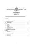
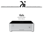
®
intercom systems user’s manual
The Basics
The wired axxent intercom system was developed for safe communication between the members of the system operating staff.
Contrary to “walkie talkies” all members communicate with each
other in full duplex, meaning simultaneous speaking and listening.
The system is based on the successful “party line technique”,
which means that all communicating participants can listen and
talk with each other (like in a conference) meaning that there is
no necessity to address the individuals, for example via a matrix
system.
The components are connected with each other via standard
3pin XLR, like regular balanced microphone cables, which are inexpensive and reliable and available almost everywhere. Total cable distance of 100 metres and more have been tried with the system without problems. Each intercom component is equipped
with a minimum of 2 intercom connectors, making the system wiring easy.
A system consists of at least 2 components, e.g. 1 main station
plus a belt-pack or 2 main stations. Each station requires to be
voltage powered. Power for the beltpacks comes from a master
station via the microphone cable. Same with the signal lights. Alternatively the supply voltage can be provided by external power
supply model PS100. For talking and listening a professional
headset is used, either with one or with 2 ear muffs.
The call signalling is either handled by large separate signal
light, looped in the regular wiring or via the built in signal lights
of the components. In addition a piezo buzzer is integrated and
can be activated when required, or preferred over a light signal.
A beltpack (BP100V) also contains a vibration element, in case
the light is overlooked.
Operating the axxent intercom system is almost self-explanatory, but here some help by giving you an oversight of the controls and their purpose as well as providing info on the system
interfaces on the following pages. The index on the right hand
side will guide you trough this manual.
index
MS200 main station (front).......................2
MS200 main station (rear).........................3
BP100 Beltpack.................................................4
BP101, BP100V Beltpack................................5
loudspeaker station CP100S (front)............ 6
loudspeaker station CP100S (rear)..............7
MS100 main station.........................................8
PS100 power supply.......................................9
LP100 signal light........................................... 10
ILS3 signal splitter.......................................... 10
axxent e.K. · Technologiezentrum Herzbachtal · Zum Wartturm 15 · 63571 Gelnhausen
Fon: +49-6051-916 5584 · Fax: 916 55859 · [email protected] · www.axxent.de
1
®
intercom systems user’s manual
main station MS200
controls on the front side
The model MS200 is the standard main station of the axxent intercom system. It has two separate channels so that two user groups
may communicate independently. These two groups can communicate separately from each other, but can not be interconnected. The
operator of the main station, however, is able to communicate with
both groups, either separately or with both groups simultaneously.
The call buttons for both groups are also separate. One main station
can supply the operating voltage for the attached intercom components via a standard XLR microphone cable. One main station provides supply voltage for more than 10 beltpacks.
controls in detail
On the front side of the main station you will find a couple of controls and plugs. On the left the 4 pin XLR male plug (1) for connecting a headset. Close by on the right (2), is the volume control for the
earphone of the headset. Side-Tone controls (3): This control determines the volume of the headsets microphone. Adjust the volume
according to your needs. Too high levels may lead to feedback, so it
is recommended to stay below that level. The switch (4) has three
positions: microphone ON; microphone OFF and microphone PTT =
Push To Talk. The switch (5) A, A+B and B determines with which of
the user groups you communicate from the master station. BUZZER
ON OFF (6) is the ON/OFF switch for the piezo acoustical alarm.
While most likely not used during a theatre performance itself, it can
be a helpful aid for rehearsals. Push buttons (7) for the alarm light,
separately for channels A + B. 3 pin XLR female plug (8) is intended
for an external input audio signal, such as program- or music signal.
Line- and microphone levels are accepted. The input level control is
located on the right hand side of the plug, so is the switch to determine the channels you want to use, either A, B or both. The power
switch (9) is located on the right hand side of the panel.
We recommend to connect all components prior to turning on the
unit. Controls and connectors on the rear side are described on the
following page ––>
axxent e.K. · Technologiezentrum Herzbachtal · Zum Wartturm 15 · 63571 Gelnhausen
Fon: +49-6051-916 5584 · Fax: 916 55859 · [email protected] · www.axxent.de
2
®
intercom systems user’s manual
main station MS200
10
11
12
13
14
15
16
16
17
controls on the rear side
Left is the power cord outlet (10) and the fuse holder (11). In case
the fuse should blow, please make sure you replace it with the same
type e.g. 230 V, 1 Ampère, slow blow (regular commercially available
glass fuse, 5 x 20 mm). Should the new fuse become defective
again you most likely have to send in the unit for repair. Further
right is the voltage selector (12) which in Europe should remain in
the 230 V position. When switching to 110 V by accident the unit
might be damaged and no warranty claim will help.
LINE OUT: This is a 3 pin XLR male line level output (13) providing a
signal for recording, loudspeaker feed etc. The channels to be recorded can be determined by the close by switch (14).
LINE IN: 3 pin XLR female line level inputs. Here again the channel
selector is located right hand (15). This input is also equipped with
the (somewhat hidden) level control VOL. (14) The volume is adjusted with a mini crew driver.
CHANNEL B – (16) These XLR connectors (male) carry the intercom
connection signals. The three XLR plugs are wired in parallel, which
means you do not have to care which of the connectors you use.
CHANNEL A – (17) the same applies to channel A. Please make sure
that you only use high quality shielded microphone cable for the
interconnection of the components, thereby avoiding hum and
noise.
axxent e.K. · Technologiezentrum Herzbachtal · Zum Wartturm 15 · 63571 Gelnhausen
Fon: +49-6051-916 5584 · Fax: 916 55859 · [email protected] · www.axxent.de
3
®
intercom systems user’s manual
beltpacks
Beltpack BP100
is the second important component of an intercom system: The
beltpack is – as the name indicates – normally worn on the belt,
using the steel clip. In case you break this rugged clip we recommend to order a new one as a replacement part. The front side of
the BP100 carries the controls, while all connectors are located on
the rear side.
1
2
3
4
5
CALL-button (1), with light indicator. Below is the buzzer ON/OFF
switch (2), to generate an acoustical call buzz. In the middle of the
panel is the 3-position microphone switch: ON (permanently), PTT =
Push To Talk and OFF (3). Finally the volume control for the earphone (4) and the SIDE-TONE-control (5) for setting the cue volume of your own microphone. For all these controls the same hints
apply as outlined for the master station MS200.
6
7
8
Rear side: Left is the 4 pin XLR male connector (6) for your headset.
Right from this is the three pin XLR input (7) for the microphone
cable from the main station or from other beltpacks and the 3 pin
XLR male (8) connector for looping through the intercom signals
to further beltpacks, signal lights, or loudspeaker stations.
axxent e.K. · Technologiezentrum Herzbachtal · Zum Wartturm 15 · 63571 Gelnhausen
Fon: +49-6051-916 5584 · Fax: 916 55859 · [email protected] · www.axxent.de
4
®
intercom systems user’s manual
beltpacks
The beltpack BP100V
The difference between this model and the above described version BP100 is the lack of a piezo buzzer, providing a vibration
alarm instead of it. This vibration alarm consists of a small rectangular unit with attached cable and a 3.5 mm phone jack, connecting to the BP100V. The vibration alarm unit can be carried in your
pocket and calls your attention in case the signal light is not noticed. All other controls and connectors are identical to the beltpack BP100.
The beltpack BP101
This third axxent beltback model offers light and tone alarm like the
model BP100 and a phone plug input to connect a vibration alarm
module like the BP100V. This external module is available as an option.
An additional feature is a switch, located on the lower left hand side,
allowing the alarm signal to either last for the time the CALL botton
is depressed, or (in the second position) for a period of appr. 4 seconds. The rear connectors are identical to those on the other axxent
beltpack models.
axxent e.K. · Technologiezentrum Herzbachtal · Zum Wartturm 15 · 63571 Gelnhausen
Fon: +49-6051-916 5584 · Fax: 916 55859 · [email protected] · www.axxent.de
5
®
intercom systems user’s manual
main-/speaker station CP100S
CP100S half 19“ mainstation with loudpeaker
Due to its compact size this loudspeaker station is also favourably used as
a small main station. It may either be mounted in the optional 19” rackmount kit RME100, or surface mounted (rubber feet
included). Using the optional wallmount kit WMK100
it even can be mounted on a wall. The model CP100S
may be looped in to the signal chain like any of the
other intercom components. It derives its supply voltage from the included power supply PS24 (for more then 10 additional other units, like stations, beltpacks or signal lights) or via microphone cable from the main
station. The optional model PS48 privides power supply for more then 20
units.
1
2
3
4
5
6
Wall-Mount-Kit WMK100
7
Controls on the front side
HEADSET connector (1); MIC connector (2). Instead of connecting a
headset here these inputs also can be used for connecting another
external microphone such as a gooseneck or handheld (dynamic). In
this case the loudspeakers will be used instead of the earphone. In
case you use a headset you can disengage the built-in loudspeaker
with the SPKR switch (3). Right from this you will find the CALL button (4). Beneath is an ON/OFF switch for the buzzer alarm. The 3-position talk switch (5) has the options: OFF, PTT (Push To Talk) and ON.
The level of the loudspeaker or the earphone of the headset is controlled by the potentiometer (6). SIDE-TONE: To control the cue volume of your own microphone (7).
axxent e.K. · Technologiezentrum Herzbachtal · Zum Wartturm 15 · 63571 Gelnhausen
Fon: +49-6051-916 5584 · Fax: 916 55859 · [email protected] · www.axxent.de
6
®
intercom systems user’s manual
main-/speaker station CP100S
1
2
3
4
Controls and connectors on the rear side
LINE IN (1): This is the XLR intercom connector for the microphone
connection cable to the main station.
LINE OUT (2): Serves as loop through to other intercom stations. On
the right hand is the RJ-45 connector (3) which can be used for
power supply of the unit, either from the included power supply PS24
or via microphone cable from the main station.
On the right hand side is the power supply input (3). The unit needs
approximately 24 volts DC. The included power suppy PS24 not only
delivers power for the CP100S but also for more then 10 additional
components. If you need supply for over 20 units, we recommend
use of the optional power suppy PS48. The PS48 also has a ground
connector for hum free operation.
On the lower right side you will find the switch LINE TERMINATION
(4). We recomment to activate this switch (ON). It’s because it inserts a 300 ohms resistor for stabalising the normally somewhat
“shaky” partyline signal chain. Within the intercom system only one
line termination must be activated in order to avoid attenuation of
the signal level.
axxent e.K. · Technologiezentrum Herzbachtal · Zum Wartturm 15 · 63571 Gelnhausen
Fon: +49-6051-916 5584 · Fax: 916 55859 · [email protected] · www.axxent.de
7
®
intercom systems user’s manual
one channel main station MS100
Most important features of the MS100: Main station for 19" rack mounting 1 U
(44 mm). Like the main station MS200 it operates as power supply for more
than 10 beltpacks.. The model MS100 offers a 12 V cigarette lighter which
may also serve as power supply for a mobile refrigerator or to charge a cellphone. Also two rack light BNC connectors are provided.
1
1
2
2
3
3
4
5
4
6
7
8 9
10
11
12
13
5
Controls on the front side
ON/OFF switch for both rack lights (1). BNC connector as input for rack light
(2). Space for accessories, such as a mobile phone (3), 12 V cigarette lighter
(4), SIGNAL light as call indicator (5), CALL button with light (6/7). Below
this button is the ON/OFF switch for the BUZZER tone (6/7), switch for microphone: PTT= push to talk, OFF and ON (8), VOLUME control (9) for the
earphone of the headset. SIDE TONE (10) volume control to set the cueing
level of your own microphone. COM CONNECT (11) is a 3 pin XLR male plug
for intercom connection. This for example connect to a beltpack or to another signal light (via a mic cable). HEADSET connector: 4 pin XLR male (12).
RACKLIGHT BNC connector (13). POWER ON/OFF switch (14).
Attention: switch the unit on after you made all the connections to the
intercom components.
Controls on the rear side
Fuse holder (1). Standard glass fuses 5 x 20 mm, 1 A, slow blow, are used.
Replace only with fuse of the same type. In case the fuse blows again the
unit has to be sent in for repair. Voltage connector 110/230 V (2): in Europe
this selector must be in the 230 V position. Switching to a 110 V position may
damage the unit (no warranty). Power cord outlet (3), LINE-OUT (4) = 3 pin
XLR male connector line level for recording or as a feed for PA systems. COM
CONNECT (5) this 3 pin XLR male connector is the intercom output for connection of several intercom components using standard microphone cables.
axxent e.K. · Technologiezentrum Herzbachtal · Zum Wartturm 15 · 63571 Gelnhausen
Fon: +49-6051-916 5584 · Fax: 916 55859 · [email protected] · www.axxent.de
8
®
intercom systems user’s manual
power supply PS100
Normally beltpacks, loudspeaker stations or signal lights receive their
operating voltage from an intercom main station. These main stations are
normally intended to be rack mounted. During the past few years a trend
to the use of digital audio mixing consoles could be observed, eliminating
in many cases the so called „side racks” since these mixing consoles also
have dynamic processors on board.Sound engineers therefore avoid additional 19” equipment. We have reacted to this trend and developed an
external power supply for small intercom components such as beltpacks.
The voltage supply is delivered by a standard microphone cable. With the
new power supply PS100 up to 6 beltpacks may be connected.
1
2
3
4
5
6
7
Controls on the front side
Power switch (1) – Please switch on only after connecting all other components. Voltage selector 110/230 V (2). In Europe leave this selector in
the 230 V position otherwise the unit can be damaged. Fuse holder with
glass fuses, 5 x 20 mm, 200 mA slow blow (3). Only replace with fuses of
the same current. In case the fuse blows again sent in the unit must be
return for repair. OVERLOAD LED (4) indicates that possibly too many
components have been connected. POWER LED (5).
Controls on the raer side
On the rear side of the power supply PS100 you will find the power cord
outlet and the two XLR intercom connectors (6+7). A total of 6 beltpacks
may be powered by the PS100 (for example 3 beltpacks per output or 6
on one output). The case of the power supply is very rugged and made of
steel with a special coating for years of flawless operation. Rubber feet
are provided for safe surface mounting. An XLR gender changer adaptor
(Neutrik NC3FF), female to female is being proveded with the PS100
power supply. It helps in certain cases, where you don‘t have two female
XLR connections to the PS100 available.
axxent e.K. · Technologiezentrum Herzbachtal · Zum Wartturm 15 · 63571 Gelnhausen
Fon: +49-6051-916 5584 · Fax: 916 55859 · [email protected] · www.axxent.de
9
®
intercom systems user’s manual
signal lights LP100
The light dome of the LP100 is made of white matte glass and can be
noticed even at large distances. The LP100 has no controls, solely an intercom connection in-/ and output. Models with colour light indicators
are also available.
The operation voltage is carried by the microphone cable. The signal
lights may be looped into the intercom signal chain as you like, e.g. main
station, beltpack. The power is looped through. All axxent signal light
models are equipped with identical 3pin connectors.
signal splitter ILS3
In case you run into trouble with the single output on the main station
MS100 or CP100S for looping through the signal, we provide a solution
with the signal splitter ILS3. The ILS3 allows you to split an input signal
into 3 output signals at any point of the intercom system. The installation
is easy and self explanatory.
ILS3 input
ILS3 outputs
axxent e.K. · Technologiezentrum Herzbachtal · Zum Wartturm 15 · 63571 Gelnhausen
Fon: +49-6051-916 5584 · Fax: 916 55859 · [email protected] · www.axxent.de
10