1
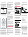
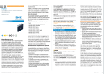
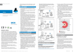
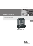
en O p e rat i n g I n s t ruc t io n s • Ethernet version (RFU620-101xx), with heating for ambient temperatures as low as –40°C • Serial version (RFU620-104xx) • PoE version (RFU620-105xx), PoE = Power-over-Ethernet Each series contains variants for regional assignment (placeholder xx above, see type label on the device) of the operating license and the carrier frequency range (for an overview see “Technical specifications (excerpt)”, page 5). RFU62x In this document, the RFU620 interrogator is simply referred to as the “RFU620”, unless a clear distinction needs to be made between variants. About this document RFID interrogator (UHF) with internal antenna Mid range RFU620-101xx RFU620-104xx RFU620-105xx These operating instructions apply to all variants of the RFU620. They allow you to commission the RFU620 quickly and easily in an ambient temperature range from 0°C to +50°C and to achieve initial read results with transponders. They describe the commissioning process for an application with one RFU620, starting with its default setting. Device variant RFU620-10100 (Ethernet version, regional assignment: Europe) is used as the basis for the examples given. The CDB620 connection module is used, for example, for the industrial-standard signal distribution of the RFU620. With the exception of the electrical connection, other variants are commissioned in the same way. Supplementary and other applicable documents More detailed information about mounting and electrical installation as a stand-alone device is available in the & RFU62x RFID Interrogator (UHF) Technical Information, No. 8015930. This describes and presents: Correct use The RFU620 interrogator (standard device) is an intelligent SICK-IDpro sensor from the RFU62x product family. It is used for the automatic, fixed identification of radio-based data carriers on moving or stationary objects and their management. As a compact reading and writing unit, the RFU620 has an integrated antenna. It processes all standard passive transponders in accordance with ISO-/IEC-18000-6C and EPCglobal UHF C1G2 in the regional UHF carrier frequency range. Thanks to its intelligent process logic it can be used either as a stand-alone solution or as part of a group in a network. The RFU620 sends the read results to a higher-level computer for further processing via its host interface. Or it receives commands for data carrier management (write, read, etc.) via this interface. Correct use also includes compliance with all information in these operating instructions and the supplementary & RFU62x RFID Interrogator (UHF) Technical Information, No. 8015930. The RFU62x product family consists of 3 version series which are distinguished by their functionality (including type of data interface) and the design of the electrical connection: • Optional mounting accessories (brackets) • Measures for electrical installation of the RFU620101xx in an ambient temperature range from 0°C to –40°C • The suppression of ground potential equalization currents in applications with widely distributed systems • Pin assignments and lead color assignments of cables • Electrical wiring plans for the CDB620-001 connection module, based on the RFU620 • Reference list and license texts for open source software used in the firmware Operating the RFU620 in a fieldbus with line topology The optional integration of the RFU620 in the PROFIBUS DP, PROFINET IO or EtherCAT® fieldbus is described in the relevant & operating instructions for the CDF600-21xx, -2200 or -0300 fieldbus module see “Sources for obtaining additional information, page 6”. Information about configuration can be found in the online help function of the SOPAS ET configuration software. The listed documents are available in PDF format on the SICK product pages on the Internet: www.mysick.com/en/rfu62x, .../CDF600-2 and .../CDF600 In order to view PDF documents on a PC, PDF visualization software is required, e.g. Acrobat Reader (http://get.adobe. com/reader). 8015928/YAJ1/2014-04-24 • Subject to change without notice • SICK AG • Waldkirch • Germany • www.sick.com Safety information • This chapter concerns the safety of commissioning personnel as well as operators of the system in which the RFU620 is integrated. • Read these instructions carefully before commissioning the RFU620 in order to familiarize yourself with the device and its functions. The operating instructions are considered a part of the device and must be kept in an accessible location in the immediate vicinity of the RFU620 at all times! • For country-specific particulars to consider when operating the RFU620, see “Operational restrictions, page 5”. aa Danger Health hazard due to high-frequency electromagnetic radiation! The RFU620-10x00 (region: Europe) is designed for operation in accordance with ETSI EN 302208. During operation, the human exposure regulations covered by EN 50364 must be observed. >> In order to limit human exposure to electromagnetic fields, suitable safety distances must be maintained during both short-term and long-term work in the radiation range of the antenna. Minimum distances to be maintained between the antenna and the human body: 10 cm during long-term transmission and max. radiation power of the antenna of 250 mW (24 dBm) as per ETSI. The RFU620-10x01 (region: USA/Canada) satisfies the limit values of the FCC for exposure to radiation in an uncontrolled environment. >> During operation, a safety distance of at least 20 cm must be maintained between the antenna and the human body. • The following requirements must be met if the IP 67/65 enclosure rating is to be maintained during operation (otherwise, the device will no longer meet the conditions for any specified IP enclosure rating): • The side cover of the USB female connector/Micro-SD card slot must be screwed tight to the device • The SICK cables plugged into the M12 connections must be screwed tight • Electrical connections that are not being used (RFU620101xx) must be fitted with protective caps/plugs that are screwed tight (as in the delivery condition) The RFU620 must only be used for a short period without a cover in order to insert or remove the memory card or use the USB interface temporarily. During this time, protect the device against moisture and dust. • Opening the screws of the RFU620 housing will invalidate any warranty claims against SICK AG. For further warranty provisions, see the General Terms and Conditions of SICK AG, e.g. on the delivery note of the RFU620. • Data integrity: SICK AG uses standardized data interfaces, such as stan- dard IP technology, in its products. The emphasis here is on the availability of products and their features. SICK AG always assumes that the integrity and the confidentiality of the data and rights which are affected by the use of these products will be ensured by the customer. In all cases, appropriate security measures, such as network separation, firewalls, virus protection, and patch management, must be taken by the customer on the basis of the situation in question. Commissioning and configuration Scope of delivery • RFU620 in the version ordered (functionality/design of the connection, regional assignment). Electrical connections fitted with protective caps/plugs (RFU620-101xx). Without connecting cables (RFU620-101xx, -105xx) and brackets. • Regionally assigned, printed operating instructions: see “Device overview”, page 5 Other language versions may be available in PDF format on the RFU620 product page on the Internet: www.mysick.com/en/rfu62x. Step 1: Mounting and alignment Equipment required • 2 x M6 or 4 x M5 screws for mounting the RFU620 on a mounting device (bracket) provided by the customer. Screw length is dependent on the mounting base (wall thickness of the bracket). When using an optional SICK bracket, the screws for mounting the RFU620 on the bracket are included in the scope of delivery of the bracket. Mounting requirements • The permissible ambient conditions for operating the RFU620 must be observed, e.g. assigned region, ambient temperature, ground potential ( see “Technical specifications (excerpt), page 5” and “Step 2: Electrical installation, page 2”) • The device must be mounted using all 2 M6 or 4 M5 threaded mounting holes provided ( see “Device layout”, page 3). • Stable mounting device with sufficient load-bearing capacity and suitable dimensions for the RFU620. Weight approx. 780 g (without cables). Dimension drawing see “Device layout”, page 3 • No electrically conductive material between transponder and RFU620. Mounting the RFU620 1. Select a suitable mounting location for the RFU620. The mounting location and position depend on the antenna field of the RFU620 and the transponders used. 2. Optional: Attach the SICK mounting accessories ordered separately (mounting kit 1, 2, 3, 4 or 5) to the RFU620; see “Mounting” chapter in the & RFU62x RFID Interrogator (UHF) Technical Information, No. 8015930. Otherwise, mount the RFU620 on the bracket provided RFU62x | SICK 1 by the customer using the 2 or 4 screws. Screw the M6 screws max. 7 mm, M5 max. 9 mm into the threaded mounting holes ( see “Device layout, page 3”). 3. Align the surface of the integrated antenna of the RFU620 (front face) to the data carrier on the object. While doing so, take into account the shape, alignment, and dimensions of the antenna field ( see figure below). Avoid as far as possible any large metal surfaces positioned to the front. If this is not possible, do not mount the antenna plane parallel with the surface. e. g. 10° Selecting the approach angle of the RFU620 in the case of a large metal surface on the front 4. Ensure that there are no objects (including personnel) between the RFU620 and the transponder during the write or read process. These will absorb/reflect the generated UHF field and thereby reduce the scanning range. Operating range of the read/write field on the RFU620 –15° –45° –60° –75° –90° 0° 5 2 –1 –4 –7 –10 –13 –16 –19 –22 –25 –28 15° 30° 45° 60° 75° 90° –105° 105° –120° 120° 135° –135° –150° –165° 180° 165° 150° Azimuth plane (horizontal) Elevation plane (vertical) Radiation pattern: measured antenna gain in dBic at 866.5 MHz, RHCP (Right Hand Circular Polarized) The UHF field is influenced by its environment, making it impossible to provide a “clear” demarcation of the scanning range. Application-specific reflections can result in both overreaches and “holes”. In addition to the read results, the RFU620 can also output diagnostic data, which gives an indication of the write and read quality. This data can be used when setting up the system in order to achieve optimum read results. Another key factor in determining the scanning range is the quality of the transponder (antenna gain, integrated transponder IC and associated sensitivity, reflected energy) 2 RFU62x | SICK CDB620 connection module >> Mount the CDB620 connection module in the vicinity of the RFU620. If you are using the serial data interfaces (RS232), we recommend a max. distance of 5 m. Mount the CDB620 in such a way that the device remains accessible at all times. See & CDB620-001 Connection Module Operating Instructions (No. 8012119), which are supplied in printed form with the device. Step 2: Electrical installation Metal surface –30° and the object itself (plastic, wood, metal). The radiation pattern shown for the antenna of the RFU620 was produced for example purposes in a reproducible environment (absorber chamber) and can therefore only be used as the basis for specific applications to a certain extent. • The electrical installation must only be performed by electrically qualified persons. • Standard safety requirements must be met when working in electrical systems. • Electrical connections between the RFU620 and other devices may only be created or disconnected when there is no power to the system. Otherwise, the devices may be damaged. • When using connecting/extension cables with an open end, make sure that bare wire ends are not touching (risk of short-circuit when the supply voltage is switched on). Take appropriate measures to isolate the wires. • Wire cross-sections in the supply cable from the customer's power system should be designed in accordance with the applicable standards. If the supply voltage for the RFU620 (10 V DC to 30 V, 20 V DC to 30 V when using the integrated heating, 48 V DC or 57 V DC with the PoE version) is not supplied via the optional CDB620 connection module, the RFU620 must be protected by a separate slow-blow fuse with a rating of 0.8 A at the start of the supply circuit. • All circuits connected to the RFU620 must be designed as SELV circuits. The power supply/power supply unit must satisfy the requirements of SELV in accordance with the currently applicable EN 60950-1. (SELV = Safety Extra Low Voltage) aa Danger supply immediately and have the damage repaired. >> See the “Electrical installation” chapter in the & RFU62x RFID Interrogator (UHF) Technical Information, No. 8015930 on the product page on the Internet: www.mysick.com/en/rfu62x for measures for eliminating hazards. Connecting the RFU620 depending on the model c.PoE version RFU620-105xx Connection module CDB620-001 1 2 ... ... PD Ethernet Serial RFU620-101xx Configuration Diagnostics SOPAS GND DC 12 V ... 30 V „PoE“ e.g. cable no. 6049728 (2 m) “Power/...” “Ethernet” e.g. cable e.g. cable no. 2055419 (2 m) no. 6034414 (2 m) 1. Connect the communication interface (e.g. Ethernet) of the RFU620-101xx directly to the PC. 2. Connect the 17-pin M12 male connector (“Power/AUX/ CAN/I/0”) via a suitable adapter cable (e.g. No. 2055419, 2 m) to the 15-pin D-Sub-HD female connector of the CDB620. b.Serial version Serial Connection module CDB620-001 ... AUX ... GND DC 12 V ... 30 V 11 10 12 VS Sens 1 Reading SGND trigger PSE DC 48/57 V Electrical connection of the RFU620-105xx for commissioning Electrical connection of the RFU620-101xx for commissioning 1 2 PoE Switch ... 11 10 12 VS Sens 1 SGND Reading trigger Configuration Diagnostics SOPAS Ethernet a.Ethernet version Configuration Diagnostics SOPAS e.g. cable no. 2014054 (2 m) RFU620-104xx Serial >> Connect the 8-pin M12 female connector via a suitable cable (e.g. No. 6049728, 2 m) to the PoE switch. d.General information 1. If necessary, connect a read pulse sensor, such as a photoelectric switch, to the “Sens 1” switching input of the RFU620 via the CDB620. Does not apply to RFU620-105xx. See the “Electrical installation” chapter of the & RFU62x RFID Interrogator (UHF) Technical Information, No. 8015930. 2. Supply power to the RFU620. RFU620-101xx/-104xx: 10 to 30 V DC, RFU620-101xx: when used in the low-temperature range below –25°C: 20 to 30 V DC RFU620-105xx: 48 V/57 V DC according to PoE technology. After successful initialization, the “Device Ready” LED lights up green. The power supply via a power supply unit must be capable of buffering a brief power failure of 20 ms. 3. Turn on the PC and start Windows. Step 3: Configuration with PC “Power/HOST/AUX/CAN/I0” Risk of injury/risk of damage due to electrical current! Electrical connection of the RFU620-104xx for commissioning The RFU620 is designed to be operated in a system with professional grounding of all connected devices and mounting surfaces to the same ground potential. Incorrect grounding of the RFU620 can result in equipotential bonding currents between the RFU620 and other grounded devices in the system. This can lead to hazardous voltages being applied to metal housing, cause devices to malfunction or sustain irreparable damage and damage the cable shield as a result of a heat increase, causing cables to set alight. 1. Connect the 15-pin D-Sub-HD male connector of the RFU620-104xx connecting cable to the corresponding female connector on the CDB620. In order to maintain enclosure rating IP 65 for the connecting cable of the device when using an optional extension cable (e.g. No. 2043413, 2 m), use the optional rubber seal (No. 4038847) between the male connector and the female connector of the 15-pin D-Sub-HD connection and screw the connection in place. 2. Connect the serial AUX interface (RS-232) of the RFU620-104xx to the PC. To do so, connect the internal 9-pin D-Sub “AUX” male connector of the CDB620 with • Ensure that the ground potential is the same at all grounding points. • If the cable insulation is damaged, disconnect the power a null-modem cable (e.g. No. 2014054, 2 m) to the PC (9‑pin D-Sub male connector). If the PC does not have an RS-232 interface, use an additional suitable adapter cable with integrated RS-232 <> USB converter (e.g. No. 6042499, 1.5 m). The SOPAS ET configuration software is used by default to adapt the RFU620 parameters to the application and to the perform diagnostics in the event of an error. a.Installing and starting the configuration software 1. Download and install the latest version of the SOPAS ET configuration software, as well as current device description files (*.sdd), from the online product page for the software: www.mysick.com/en/SOPAS_ET by following the instructions provided there. Select the “Complete” option as suggested by the install wizard. Administrator rights may be required on the PC to install the software. 2. Start the “SOPAS ET” program option after completing the installation. Path: Start > Programs > SICK > SOPAS ET Engineering Tool > SOPAS. 3. Establish a connection between SOPAS ET and RFU620 via 8015928/YAJ1/2014-04-24 •Subject to change without notice • SICK AG • Waldkirch • Germany • www.sick.com Device description the wizard which opens automatically. In order to do this, select the desired communication interface for searching in the connection wizard. (Default Ethernet address: IP address: 192.168.0.1, Subnet mask: 255.255.255.0) SOPAS ET establishes communication with the RFU620 and loads the associated device description file for the RFU620. The Quickstart tab opens. Device layout 113.9 RFU620-101xx Light output of the LEDs in Quickstart mode Meaning Lights up with medium intensity UHF field present High intensity slow flashing 1 transponder in field High intensity rapid flashing 2 or more transponders in field In the SOPAS ET navigation tree on the left, edit the required RFU620 tabs for the application using the additional entries under Parameters. These include antenna configuration, filter functions, transponder processing, object trigger control (e.g. via “Sensor 1” switching input), data processing, data output, interfaces, function of the switching inputs and outputs, and the possible use of an optional Micro-SD memory card. 4. On the Antenna configuration tab, the transmitting power for the antenna can be set using sliders. c.Accessing the data on a transponder 1. In order to access the memory area of a transponder, in Quickstart click the Stop button. 2. Mark the desired transponder (click it with the mouse). 3. Click the Transponder access button. The Tag Access tab now displays the content of the selected transponder. 20.1 25 0 3 20.1 RFU620-104xx Side cover opened 0 4 25 RFU620-101xx ß 9 130.8 116 30 55.3 7 6 x 7.7 (= 46.2) à 5 á 25.5 6 0 â 7 71.9 76.7 RFU620-105xx Important! The automatic triggering in Quickstart mode is intended for (initial) commissioning and not for permanent use when operating the RFU620 under real conditions. RFU620-105xx Important! d.Continuing the configuration process In the default configuration, the blue light output of the process feedback LEDs (5) in the corners of the RFU620 antenna cover indicates whether a UHF field is present and transponders have been detected. 103.3 2 137.4 SOPAS ET: Tag Access display window 0 50 1 The TID (Tag Identifier) of the transponder cannot be changed. SOPAS ET: Display of several detected transponders in the Quickstart window 20.1 130.8 1. Bring one or more standards-compliant UHF transponders into the working area of the RFU620 antenna. The UII/EPC of the individual transponders must be different so that multiple transponders can be detected. 2. In SOPAS ET, in the Quickstart tab, click the Start button. SOPAS ET generates an automatic reading cycle and lists the detected transponders in the Quickstart window. 34.4 0° 10 b.Detecting a transponder in Quickstart mode 1 “Power/AUX/CAN/I/O” connection (17-pin M12 male connector, A-coded) 2 “Ethernet” connection (4-pin M12 female connector, D-coded) 3 “PoE” connection (8-pin M12 female connector, X-coded) 4 ”Power/HOST/AUX/CAN/I/O” connection (15-pin D-Sub HD male connector, cable 0.9 m) 5 4 x LED multi-color (Process Feedback) 6 7 x LED (status indicators) 7 Cover with integrated antenna 8 2 x screws (Torx T8), captive, for side cover 9 USB female connector, type Micro-B ß Slot for Micro-SD card à 4 x threaded mounting holes M5, 9 mm deep, for alternatively mounting the RFU620 á Pressure compensation valve (ventilation element) â 2 x threaded mounting holes M6, 7 mm deep, for mounting the RFU620 71.9 76.9 Configuration: Example setting for the internal antenna RFU620-104xx 69.7 71.9 RFU620 default setting: Transmitting power: 15 dBm (30 mW) 5. Test and, if necessary, modify the specified settings when operating the system under real conditions. 8 54 e.Completing the configuration process 0 >> Permanently save the entire configuration once it has been successfully tested: button Parameter set in the RFU620: Click the button. Configuration file on the PC: Click the 18.1 8015928/YAJ1/2014-04-24 • Subject to change without notice • SICK AG • Waldkirch • Germany • www.sick.com All dimensions in mm RFU62x | SICK 3 Overview of all interfaces and connection options Status displays “Serial RS-232” (AUX 1), alternatively to Ethernet AUX port “USB” (AUX 3)**), alternatively to Ethernet AUX port RFU620-101xx Input 1 (e.g. external reading trigger) Input 2 SOPAS PC “Ethernet” (AUX 2) For block diagrams RFU620-104xx RFU620-105xx see Technical Information RFU62x (Nr. 8015930) DC 12 V ... 30 V*) Configuration Diagnostics Ethernet (e.g. indicator lamp) Output 2 Additional external inputs/outputs via CMC600 parameter cloning module Inputs/outputs = digital “Power/AUX/CAN/I/O” (AUX 1, HOST 1) “Ethernet” e.g. cable no. 2055419 (2 m) e.g. cable no. 6034414 (2 m) HOST ”Ethernet” (HOST 2) Reading result “Serial RS-232/RS-422/485” (HOST 1), alternatively to Ethernet HOST port *) RFU62x-101xx: DC 20 V ... 30 V if the integrated heating is used. Status indicators on the first display level Display Ready Result (e.g. encoder) Output 1 RF Data*) Further data processing **) e.g. cable no. 6036106 (2 m). LED Color Status O O O O Green Device ready Red Hardware fault Green Read or write successful Green UHF field switched on Green Data receipt at the serial host interface Yellow Data output at the serial host interface Green Data traffic via CAN bus Green Data traffic via Ethernet O O CAN*) O LNK/ ACT O Micro-SD O Green Micro-SD card inserted and ready for operation. If the LED lights up, however, this does not indicate that the RFU620 is accessing the card! O Red Micro-SD card inserted, cannot, however, be read or is defective O Orange The use of the Micro-SD card in connection with a device function has been manually configured with SOPAS ET on the “SD card required” tab. The SD card is not, however, ready for operation. Overview of pin assignments RFU620-101xx (Ethernet version) “Power/AUX/CAN/I/0” connection 3 12 2 11 13 4 1 5 16 14 10 6 9 17 15 8 7 1 2 3 4 5 6 7 8 9 10 11 12 13 14 15 16 17 M12 male connector, A-coded RFU620-104xx (serial version) “Ethernet” connection “Power/HOST/AUX/CAN/I/0” connection 4 6 3 1 2 M12 female connector, D-coded 1 2 GND 3 DC 10 V ... 30 V*) 4 CAN L TD+ D-Sub HD male connector 11 15 1 TD– 2 RD– 3 4 TD+ (RS-422/485), HOST TD– (RS-422/485), TxD (RS-232), HOST TxD (RS-232), AUX RxD (RS-232), AUX SensGND Sensor 1 (switching input 1) RD+ (RS-422/485), HOST RD– (RS-422/485), RxD (RS-232), HOST Result 1 (switching output 1) Result 2 (switching output 2) Sensor 2 (switching output 2) N.c. 5 10 RD+ CAN H N.c. 1 *) DC 20 V ... 30 V if the integrated heating is used RFU620-105xx (PoE version) 5 “PoE” connection 7 4 3 2 1 6 5 M12 female 6 connector, 7 8 X-coded 1 2 3 4 5 6 7 8 TD+ TD– RD+ RD– PoE– PoE– 8 9 10 11 12 13 14 15 PoE+ PoE+ To ensure that the memory card functions reliably, only use types approved by SICK (see & RFID Product Information, No. 8016267). The memory card has no write protection that can be activated. Inserting the memory card >> To avoid damaging the memory card, make sure there is no power to the RFU620 when you insert or remove it. The card slot ( see ß in “Device overview, page 5”) can be accessed on the RFU620 behind the folding plastic cover. Maintaining the IP 67/65 enclosure rating: see “Safety information”, page 1 1. Turn off the supply voltage to the RFU620! 2. To open the cover, unscrew both screws. 3. Making sure it is in the correct position (with the contacts pointing to the rear and down, see the symbol on the card slot), insert the memory card into the card slot until it locks into place. 4. Screw the cover back on. 5. Turn on the supply voltage to the RFU620. Slot for Micro-SD card Screws, Torx T8 Micro USB female connector *) PoE version: LEDs have no function DC 10 V ... 30 V RxD (RS-232), AUX TxD (RS-232), AUX Sensor 2 (switching input 2) GND RD+ (RS-422/485), HOST RD– (RS-422/485), RxD (RS-232), HOST TD+ (RS-422/485), HOST TD– (RS-422/485), TxD (RS-232), HOST CAN H CAN L Result 1 (switching output 1) Result 2 (switching output 2) Sensor 1 (switching input 1) SensGND O = illuminated; = flashing Micro-SD memory card (optional accessory) Function The RFU620 can execute the following functions on the plugin memory card: • The internal parameter set will automatically be saved on an external storage (cloning function), if medium available. This is performed within the scope of the recommended safety concept for the parameter sets of IDpro devices. This function is triggered by saving the internal parameter set after the “permanent” option has been selected. The function is used, among other things, to conveniently transfer the parameter set to an exchange unit of the same type in the event of an error. Optional external media include a memory card which can be plugged into the device or the CMC600 parameter storage module, which can be used in the optional connection module, e.g. CDB620-001 or CDM420-0001. • Continuous recording of diagnostic read data after the first manual start, e.g. via SOPAS ET. Recording is resumed after a RFU620 restart when the function is set permanently. Other functions on request. 8015928/YAJ1/2014-04-24 • Subject to change without notice • SICK AG • Waldkirch • Germany • www.sick.com Micro-SD Serial GND DC 12 V ... 30 V*) CAN ... ... Data 1 2 The memory card is not included in the scope of delivery. USB LNK/ACT e.g. cable no. 2014054 (2 m) (no. 1042256) RF CDB620-001 The first time a parameter set is stored, we recommend that an empty memory card is used (if necessary, check and delete the contents of the card on the PC using a card reader). Optical status indicators Result Serial Ready Ethernet version RFU620-101xx 6. Once it is switched on, the RFU620 automatically detects the presence of a memory card and, depending on the card's content, behaves as follows: • If the card is empty or if it contains a parameter set that cannot be interpreted by the RFU620, the RFU620 saves its currently valid internal parameter set to the card (provided there is sufficient storage space) and starts with the internal parameter set. • If the card contains a parameter set that can be interpreted by the RFU620, the RFU620 temporarily overwrites the currently valid internal parameter set with this external parameter set. When switched off, this internal parameter set is lost. If necessary, the “Save permanently” command in SOPAS ET can be used to save the temporary parameter set permanently in the RFU620. The objective is for the internal parameter set and the external parameter set to always be identical. NOTE Risk of data loss or irreparable damage to the memory card! The “Micro-SD” (6) LED lights up green when a memory card which is ready for operation is inserted into the RFU620. RFU62x | SICK 4 In this status, the RFU620 can either read data from the card or write data to the card. Access to the card itself is not signaled by the RFU620 (compare electronic camera with memory card). The “Micro-SD” (6) LED lights up orange when, for example, a function which requires a memory card has been started manually with SOPAS ET and the card is not ready for operation (e.g. not inserted, contacts contaminated or no free storage space). >> To avoid damaging the memory card, make sure there is no power to the RFU620 when you insert or remove it. >> If parameter values are changed with the “permanent” option in the RFU620 using the SOPAS ET configuration software while the memory card is inserted or if functions are started which access the memory card (e.g. logging of data), do not remove the memory card and do not switch off the supply voltage. >> In order to remove the memory card in a controlled manner while working with SOPAS ET when the RFU620 is switched on, select the Remove card function under Analysis tools/MicroSD card and wait for confirmation from SOPAS ET. Technical specifications (excerpt) Model name RFU620-10xxx Model name RFU620-10xxx Scanning range Typically up to 1 m (depending on the transponder used and ambient conditions) Optical indicators Serial RS-232/422/485 RFU620-101xx/-104xx only: HOST (0.3 kBd ... 115.2 kBd) for data output 7 x RGB LED (status indicator) on front top/ side 4 x RGB LED (process feedback), Function/color can be adjusted via SOPAS ET Serial RS-232 RFU620-101xx/-104xx only: AUX (57.6 kBd) for configuration USB AUX (USB 2.0) for configuration CAN RFU620-101xx/-104xx only: CAN (CANopen®), 20 KBit/s ... 1 MBit/s. Max. bus length 30 m Ethernet RFU620-101xx/-105xx only: HOST (TCP/IP, PROFINET IO, Ethernet-IP) AUX (TCP/IP) 10/100 MBit/s, Services: DHCP, NTP, HTTP Fieldbus PROFIBUS DP RFU620-101xx/-104xx only: HOST via external CDF600-21xx module Fieldbus PROFINET IO RFU620-101xx/-104xx only: HOST via external CDF600-2200 module Fieldbus EtherCAT® RFU620-101xx/-104xx only: HOST via external CDF600-0300 module (Gateway mode) Digital switching inputs RFU620-101xx/-104xx only: 2 x physical, 2 x additional external via optional CMC600 module in the CDB620/CDM4200001 connection module Vin = max. 30 V, Iin = max. 5 mA Opto-decoupled, reverse polarity protected. Adjustable debounce time Digital switching outputs Model name RFU620-10xxx Regional assignment Model-dependent, see Table 2 Firmware version Model-dependent, see Table 2 Carrier frequency Model-dependent, see Table 2 Transmitting power 1 internal antenna, adjustable. Model-dependent, see Table 2 Internal antenna Circularly polarized. Axial ratio typically 2 dB (ETSI), 3 dB (FCC) Opening angle 100° (ETSI), 100° (FCC) Front-to-back ratio typically > 7 dB (ETSI), > 7 dB (FCC) Protocol air interface EPCglobal UHF Class 1 Generation 2 ISO/IEC 18000-6C Electrical connections RFU620-101xx/-104xx only: 2 x physical, 2 x additional external via optional CMC600 module in the CDB620/CDM4200001 connection module Vout = VS – 1.5 V, Iout ≤ 100 mA. Short-circuit proof, temperature protected, not electrically isolated from the supply voltage RFU620-101xx: 1 x 17-pin M12 male connector, 1 x 4-pin M12 female connector RFU620-104xx: 1 x cable, 0.9 m with 15-pin D-Sub-HD male connector RFU620-105xx: 1 x 8-pin M12 female connector All: 1 x 5-pin USB female connector, type Micro-B 1 x 8-pin Micro-SD card slot Parametric data backup Optional: Via plug-in Micro-SD card or externally via CMC600 module in the CDB620/CDM420-0001 connection module Supply voltage All voltages: As per SELV in accordance with currently applicable EN 60950-1 RFU620-101xx/-104xx: 10 V ... 30 V DC RFU620-101xx: 20 V ... 30 V DC when using the integrated heating (from –25°C) RFU620-105xx: 48 V/57 V DC according to PoE technology Power consumption Operation: All: Typically 8 W (with switching outputs without load and full transmitting power) RFU620-101xx: Also maximum 12 W for heating from –25°C Readiness (standby): All: Typically 3 W Housing/weight Aluminum/approx. 780 g Safety EN 60950-1: 2006-04/A11: 2009-03/ A1: 2010-03/A12: 2011-02 Electrical protection class III according to EN 61140: 2006-08 Enclosure rating Acc. to EN 60529: 1991-10/A2: 2000-02 IP 67: RFU620-101xx/-105xx IP 65: RFU620-104xx MTBF 23 years Radio equipment type approval Model-dependent, see Table 2 EMC Radiated emission: EN 61000-6-3: 2007 + A1: 2011. Electromagnetic immunity: EN 61000-6-2: 2005-08 Vibration resistance Shock resistance EN 60068-2-6: 2008-02 Ambient temperature RFU620-101xx: Operation: –40°C ... +50°C RFU620-104xx/-105xx: Operation: –25°C ... +50°C All: Storage: –40°C ... +70°C EN 60068-2-27: 2009-05 Permissible relative air humidity 0 % ... 90 %, non-condensing Time NTP - Network Time Protocol/none *) ERP = Equivalent radiated power. **) EIRP = Equivalent isotropic radiated pwr. Table 1 Device overview Regional assignment1) Radio equipment type approval Firmware Carrier frequency range Transmitting power of the internal antenna Device designation Part no. Languages of delivered operating instructions Europe, South Africa ETSI EN 302 208 V.1.4.1 From V.1.40 865.6 ... 867.6 MHz Max. 250 mW (ERP) RFU620-10100 RFU620-10400 RFU620-10500 1062599 1062600 1062601 English (no. 8015928), German (no. 8015927) USA/Canada FCC Part 15.247 From V.1.40 902.75 ... 927.25 MHzs Max. 320 mW (EIRP)3) RFU620-10101 RFU620-10401 RFU620-10501 1062602 1062603 1062604 English (no. 8015928), German (no. 8015927) India ETSI EN 302 208 V.1.4.1 On request 865.6 ... 867 MHz Max. 250 mW (ERP)2) RFU620-10103 RFU620-10503 On request 1069453 English (no. 8015928), German (no. 8015927) Brasilia ANATEL RESOLUTION No. 506 On request 90275 ... 928 MHz Max. 320 mW (EIRP) RFU620-10104 1069677 English (no. 8015928), Portuguese (no. 8017353) China SRRC From V.1.50 920.625 ... 924.375 MHz Max. 200 mW (ERP)2) RFU620-10105 1068728 English (no. 8015928), Chinese (no. 8017351) Japan ARIB STD-T107 From V.1.50 916.8 ... 920.4 MHz Max. 320 mW (EIRP)3) RFU620-10107 1068727 English (no. 8015928), Japanese (no. 8017352) 1) Further country variants on request. 2) ERP = Equivalent Radiated Power. 3) EIRP = Equivalent Isotropic Radiated Power. Table 2 5 RFU62x | SICK 2) 3) For further technical specifications, see the Online data sheet on the product page: www.mysick.com/en/rfu62x. Warnings Note Operational restrictions When delivered, the frequency band of the RFU620 is configured in such a way that it can be operated in the following assigned regions without interfering with protected frequencies (such as mobile communications): • RFU620-10x00 in the Europe region • RFU620-10x01 in the USA/Canada regions • RFU620-10x03 in the India region • RFU620-10x04 in the Brasilia region • RFU620-10x05 in the China region • RFU620-10x07 in the Japan region The operation of the same RFU620 in other regions can interfere with protected frequencies. >> Only use the RFU620 in the region for which it has been approved. >> When reselling the RFU620, inform the buyer of the regional assignment. • France: The RFU620 must not be operated within a 20 km radius of 13 military zones. • Lithuania: In Lithuania there may be restrictions (extent not currently known). • Russia: Only licensed operation is possible in Russia. • USA: This device complies with Part 15 of the FCC Rules. Operation is subject to the following two conditions: (1) This device may not cause harmful interference, and (2) this device must accept any interference received, including interference that may cause undesired operation. To comply with FCC Part 15 rules in the United States, the system must be professionally installed to ensure compliance with the Part 15 certification. It is the responsibility of the operator and professional installer to ensure that only certified systems are deployed in the United States. The use of the system in any other combination (such as co-located antennas transmitting the same information) is expressly forbidden. This equipment complies with FCC radiation exposure limits set forth for an uncontrolled environment. This equipment should be installed and operated with a minimum distance of 20 cm between the radiator and your body. • USA/Canada: This Class A digital apparatus complies with Canadian ICES-003. Changes or modifications not expressly approved by the party responsible for compliance could void the user’s authority to operate the equipment. Note: This equipment has been tested and found to comply with the limits for a Class A digital device, pursuant to Part 15 of the FCC Rules. These limits are designed to provide reasonable protection against harmful interference when the equipment is operated in a commercial environment. This equipment generates, uses, and can radiate radio 8015928/YAJ1/2014-04-24 •Subject to change without notice • SICK AG • Waldkirch • Germany • www.sick.com various electronic formats • Compatible accessories (including transponders, cables, brackets, trigger sensors) • RFU62x RFID Interrogator (UHF) Operating Instructions in English (No. 8015928) and German (No. 8015927), in other languages if available • RFU62x RFID Interrogator (UHF) Technical Information in English (No. 8015930) and German (No. 8015929) • Ordering information in the RFID product information in English (No. 8016267) and German (No. 8016266) • Publications dealing with accessories guarantee of marketability or suitability for a particular purpose. For details, see the GNU General Public License. Function modules for the RFU620 interrogator (www.sick.com/software) The firmware of the RFU620 is therefore subject to the copyrights listed below. The associated license texts that relate to the license overview provided below can be found in the RFU62x RFID Interrogator (UHF) Technical Information, No. 8015930. This can be downloaded from the RFU62x product page on the Internet: www.mysick.com/en/rfu62x Maintenance and care • Function modules for communication between a SIMATIC controller (S7-300/S7-400) and the RFU620. Function modules for other controllers on request. The RFU620 does not contain any components that require maintenance. CDF600-21xx PROFIBUS DP fieldbus module (www.mysick.com/en/cdf600-2) >> If it is dirty (e.g. metal dust), clean the antenna cover (7) (plastic) carefully using a soft, damp cloth (with a mild cleaning agent) in order to achieve the full read and write performance. • CDF600-21xx PROFIBUS DP Fieldbus Module Operating Instructions in English (No. 8015335) and German (No. 8015334), in other languages if available Transport and storage CDF600-2200 PROFINET IO fieldbus module (www.mysick.com/en/cdf600-2) Transport and store the RFU620 (here RFU620-101xx (Ethernet version) with protective plugs and caps completely screwed on) in its original packaging. Do not store outdoors. To ensure that any residual moisture present can escape, do not store the device in airtight containers. Do not expose to any aggressive substances. Storage conditions: Dry, dust-free, no direct sunlight, as little vibration as possible, storage temperature –40°C... +70°C, relative air humidity max. 90% (non-condensing). • CDF600-2200 PROFINET IO Fieldbus Module Operating Instructions in English (No. 8015922) and German (No. 8015921), in other languages if available Repair Documents on request Repair work on the RFU620 may only be performed by qualified and authorized service personnel from SICK AG. • Overview of RFU620 command strings Disassembly and disposal Any RFU620 which can no longer be used at the end of the product life cycle must be disposed of in an environmentally friendly manner in accordance with the respective applicable country-specific waste disposal regulations. The RFU620 is electronic waste and must under no circumstances be disposed of with general waste! SICK AG is not currently able to take back devices that can no longer be used. Sources for obtaining additional information Additional information about the RFU620, its optional accessories, and fieldbus modules can be found in electronic format on the following product pages on the Internet: RFU620 interrogator (www.mysick.com/en/rfu62x) • Detailed technical specifications (online data sheet) • EC declaration of conformity • Dimensional drawing and 3D CAD dimension models in CDF600-0300 EtherCAT® fieldbus module (www.mysick.com/en/cdf600) • CDF600-0300 EtherCAT® Fieldbus Module Operating Instructions in English (No. 8013919) and German (No. 8013918), in other languages if available Support is also available from your sales partner: www.sick.com/worldwide. Copyright notices EtherCAT® “EtherCAT® is a registered trademark and patented technology, licensed by Beckhoff Automation GmbH, Germany.” Copyright notices for open source programs Exclusion of liability The firmware of the RFU620 was developed using open source software. The user is exclusively responsible for any modifications made to open source components. All warranty claims shall be invalidated in this case. The following exclusion of liability applies to the GPL components in relation to the rights holders: This program is distributed in the hope that it will be of use, but with no guarantee of this; neither is there any implied 8015928/YAJ1/2014-04-24 • Subject to change without notice • SICK AG • Waldkirch • Germany • www.sick.com With regard to the other open source components, we refer you to the exclusions of liability of the rights holders contained in the license texts. List of software licenses and license texts In the RFU620 product, SICK uses unmodified open source software and, insofar as required and permitted in accordance with the relevant license conditions, modified open source software. 1. NCURSES – 5.7- License: Copyright (c) 2006 Free Software Foundation, Inc. 2. NET-SNMP - 5.7.1: 2.1 Part 1: CMU/UCD copyright notice: (BSD like) Copyright (c) 1989, 1991, 1992 by Carnegie Mellon University Derivate Work, 1996, 1998 - 2000 Copyright (c) 1996, 1998 - 2000 The Regents of the University of Carlifornia 2.2 Part 2: Networks Associates Technology, Inc copyright notice (BSD) Copyright (c) 2001 - 2003, Networks Associates Technology, Inc 2.3 Part 3: Cambridge Broadband Ltd. copyright notice (BSD) Portions of this code are copyright (c) 2001 - 2003, Cambridge Broadband Ltd. 2.4 Part 4: Sun Microsystems, Inc. copyright notice (BSD) Copyright (c) 2003 Sun Microsystems, Inc., 4150 Network Circle, Santa Clara, California 95054, U.S.A. 2.5 Part 5: Sparta, Inc copyright notice (BSD) Copyright (c) 2003 - 2011, Sparta, Inc 2.6 Part 6: Cisco/BUPTNIC copyright notice (BSD) Copyright (c) 2004, Cisco, Inc and Information Network Center of Beijing University of Posts and Telecommunications. 2.7 Part 7: Fabasoft R&D Software GmbH & Co KG copyright notice (BSD) Copyright (c) Fabasoft R&D Software GmbH & Co KG, 2003 2.8 Part 8: Apple Inc. copyright notice (BSD) Copyright (c) 2007 Apple Inc. 2.9 Part 9: ScienceLogic, LLC copyright notice (BSD) Copyright (c) 2009, ScienceLogic, LLC 3. Z-Lib 1.2.3: Copyright (C) 1995-2004 Jean-loup Gailly and Mark Adler 4. e2fsprogs-1.41.11 (UUID-license based on BSD 3-clause license): Copyright (C) 1996, 1997 Theodore Ts‘o. 5. Dropbear – 0.52.tar.bz2: Copyright (c) 2002-2008 Matt Johnston - Portions copyright (c) 2004 Mihnea Stoenescu 5.1 Import code in keyimport.c is modified from PuTTY‘s import.c, licensed as follows: PuTTY is copyright 1997-2003 Simon Tatham - Portions copyright Robert de Bath, Joris van Rantwijk, Delian Delchev, Andreas Schultz, Jeroen Massar, Wez Furlong, Nicolas Barry, Justin Bradford, and CORE SDI S.A. 6. OpenSSH – 5.1p1: 6.1 Cryptographic attack detector for ssh - source code: Copyright (c) 1998 CORE SDI S.A., Buenos Aires, Argentina. 6.2 Copyright 1995, 1996 by David Mazieres <[email protected]>. 6.3 Copyright (c) 1983, 1990, 1992, 1993, 1995 The Regents of the University of California. 6.4 Remaining components of the software are provided under a standard 2-term BSD licence with the following names as copyright holders: Markus Friedl, Theo de Raadt, Niels Provos, Dug Song, Aaron Campbell, Damien Miller, Kevin Steves, Daniel Kouril, Wesley Griffin, Per Allansson, Nils Nordman, Simon Wilkinson Portable OpenSSH additionally includes code from the following copyright holders, also under the 2-term BSD license: Ben Lindstrom, Tim Rice, Andre Lucas, Chris Adams, Corinna Vinschen, Cray Inc., Denis Parker , Gert Doering, Jakob Schlyter, Jason Downs, Juha Yrjölä, Michael Stone, Networks Associates Technology, Inc., Solar Designer, Todd C. Miller, Wayne Schroeder, William Jones, Darren Tucker, Sun Microsystems, The SCO Group, Daniel Walsh 6.5 Portable OpenSSH contains the following additional licenses: a) snprintf replacement: Copyright Patrick Powell 1995 b) Compatibility code (openbsd-compat): Some code is licensed under a 3-term BSD license, to the following copyright holders: Todd C. Miller, Theo de Raadt, Damien Miller, Eric P. Allma, The Regents of the University of California, Constantin S. Svintsoff c) Some code is licensed under an ISC-style license, to the following copyright holders: Internet Software Consortium: Todd C. Miller, Reyk Floeter, Chad Mynhier d) Some code is licensed under a MIT-style license to the following copyright holders: Free Software Foundation, Inc. 7. GNU GENERAL PUBLIC LICENSE (Version 2, June 1991): Copyright (C) 1989, 1991 Free Software Foundation, Inc., 51 Franklin Street, Fifth Floor, Boston, MA 02110-1301 USA 7.1 BusyBox 1.16.1: Copyright (C) 1989, 1991 Free Software Foundation, Inc. 7.2 iproute2-2.6.34: Copyright (C) 1989, 1991 Free Software Foundation, Inc. 7.3 kexec-tools-2.0.1: Copyright (C) 1989, 1991 Free Software Foundation, Inc. 7.4 libelf-0.8.12.: Copyright (C) 1989, 1991 Free Software Foundation, Inc. 7.5 libgcc: Copyright (C) 1989, 1991 Free Software Foundation, Inc. 7.6 ltrace-0.5: Copyright (C) 1989, 1991 Free Software Foundation, Inc. 7.7 lzo-2.03: Copyright (C) 1989, 1991 Free Software Foundation, Inc. 7.8 mtd-utils-1.3.1: Copyright (C) 1989 , 1991 Free Software Foundation, Inc. 7.9 porcps-3.2.8 (only ps used): Copyright (C) 1989, 1991 Free Software Foundation, Inc. 7.10 udev-119: Copyright (C) 1989, 1991 Free Software Foundation, Inc. 8. libstdc++: GNU LESSER GENERAL PUBLIC LICENSE (Version 3, 29 June 2007): Copyright (C) 2007 Free Software Foundation, Inc. <http://fsf.org/> 9. Glibc 2.8: 9.1 GNU LESSER GENERAL PUBLIC LICENSE (Version 3, 29 June 2007): Copyright (C) 2007 Free Software Foundation, Inc. <http://fsf.org/> 9.2 GNU GENERAL PUBLIC LICENSE (Version 3, 29 June 2007): Copyright © 2007 Free Software Foundation, Inc. <http://fsf. org/> 10.libusb: 10.1 Copyright (C) 2007-2008 Daniel Drake <[email protected]>, Copyright (c) 2001 Johannes Erdfelt <[email protected]> This library is free software; you can redistribute it and/or modify it under the terms of the GNU Lesser General Public License as published by the Free Software Foundation; either version 2.1 of the License, or (at your option) any later version.This library is distributed in the hope that it will be useful, but WITHOUT ANY WARRANTY; without even the implied warranty of MERCHANTABILITY or FITNESS FOR A PARTICULAR PURPOSE. See the GNU Lesser General Public License for more details. You should have received a copy of the GNU Lesser General Public License along with this library; if not, write to the Free Software Foundation, Inc., 51 Franklin Street, Fifth Floor, Boston, MA 02110-1301 USA 10.2 darwin backend for libusb 1.0 Copyright (C) 2008-2009 Nathan Hjelm <hjelmn@users. sourceforge.net> 8015928/2014-04-24 ∙ MT_8M ITL ∙ Printed in Germany (2014-05) ∙ All rights reserved ∙ Subject to change without notice frequency energy and, if not installed and used in accordance with the instruction manual, may cause harmful interference to radio communications. Operation of this equipment in a residential area is likely to cause harmful interference in which case the user will be required to correct the interference at his own expense. • Canada: Cet appareil numérique de la classe A est conforme à la norme NMB-003 du Canada. Le présent appareil est conforme aux CNR d’Industrie Canada applicables aux appareils radio exempts de licence. L’exploitation est autorisée aux deux conditions suivantes : (1) l’appareil ne doit pas produire de brouillage, et (2) l’utilisateur de l’appareil doit accepter tout brouillage radioélectrique subi, même si le brouillage est susceptible d’en compromettre le fonctionnement. Source codes The source codes licensed under GPL and LGPL can be ordered from the responsible SICK national representative. Contact data: www.sick.com/worldwide RFU62x | SICK 6