1
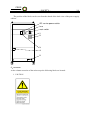
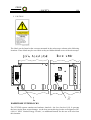
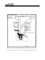
CEOS
Corrected Electron Optical
Systems GmbH
28
from the system at the main switch of the power supply cabinet. The IEC service power outlets
at the back panel are switched off. Refer to the general safety precautions in the beginning of
this manual.
As the CETCOR system is a subsystem of the electron microscope, the switch off of the
two single phase input power lines is due to the microscope provider.
6.4.2 Deenergizing of the water circuit
Different from point No. 4 above, do the following for removing the cooling water from the
lens circuit:
Close the water inlet manual hand valve. Close the regulators for the three individual
water circuits (ADL, TL2, TL1).
Connect compressed air (pressure adjustable up to 0.2 MPa, inner diameter of the hose:
4 mm) to the second manual screw driven valve at the water inlet.
Open the screw driven valve carefully. Ensure that the pressure does not exceed 0.2 MPa.
Open the regulators one after the other. The water is blown off through the water outlet.
Wait until in all flow meters the water has been blown off.
Close the screw driven inlet valve for the air. Close the manual water outlet hand valve.
Fully deenergize the cooling water circuit: Disconnect the compressed air hose and open
the screw driven manual valve for a while to release the pressure (build up by the water
outlet line in the previous step). Close the screw driven valve again. Close all regulators.
7 Replacement parts
7.1 Consumables
Consumables are needed for cleaning the vacuum liner tube of the Cs -corrector. As the liner
tube is integrated in the vacuum system of the electron microscope, follow the manual of the
microscope provider for the procedures and consumables to use for vacuum cleaning. Avoid
using items other than specified by the microscope provider. For vacuum cleaning, use the
personal protective equipment as specified by the microscope provider.
7.2 Spares
The following spares should be prepared in appropriate quantities for long use of the instrument. Avoid using items other than specified.
7.2.1 Fuse ratings
Notice: Except the fuse F1 at the back side of the power supply cabinet, fuses are not allowed
to be exchanged by the user. Internal fuses are sized for fault protection and if a fuse was
opened it would indicate that service is required. Fuse replacement of internal fuses has
to be made by service personnel.
Warning: Before changing fuses, shutdown the equipment correctly to avoid electric shock
hazards. Refer to Section 6.4.1 for the shutdown procedure.