1
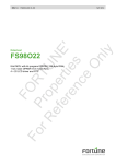
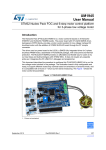
UM1900 User manual Getting started with the digital MEMS microphones expansion board based on MP34DT01-M for STM32 Nucleo Introduction The X-NUCLEO-CCA02M1 is an evaluation board based on digital MEMS microphones. It is compatible with the Morpho connector layout and is designed around STMicroelectronics MP34DT01-M digital microphones. It has two microphones soldered on board and it is compatible with digital microphone coupon boards such as STEVAL-MKI129Vx and STEVAL-MKI155Vx. The X-NUCLEO-CCA02M1 allows the acquisition and streaming of up to two microphones using the I²S peripheral and up to four coupon microphones using both I²S and SPI. It represents an easy to use and fast solution for the development of microphone-based applications as well as a starting point for audio algorithm implementation. Figure 1: X-NUCLEO-CCA02M1 evaluation board May 2015 DocID027905 Rev 1 1/15 www.st.com Contents UM1900 Contents 1 Getting started ................................................................................ 3 1.1 2 3 Hardware requirements .................................................................... 3 System requirements ..................................................................... 4 Hardware description ..................................................................... 5 3.1 USB connector and power source .................................................... 5 3.2 Audio acquisition strategy ................................................................ 5 3.3 Solder bridges configurations ........................................................... 6 3.3.1 Solder bridges roles........................................................................... 6 3.3.2 Sample use cases ............................................................................. 7 4 Connectors ................................................................................... 10 5 Board schematics......................................................................... 11 6 Layout ........................................................................................... 13 7 Revision history ........................................................................... 14 2/15 DocID027905 Rev 1 UM1900 1 Getting started Getting started This section describes the hardware requirements for the X-NUCLEO-CCA02M1 evaluation board. 1.1 Hardware requirements The X-NUCLEO-CCA02M1 is an expansion board for use with STM32 Nucleo boards (please refer to UM1724 on www.st.com for further information). The STM32 Nucleo board must be connected to the X-NUCLEO-CCA02M1 board, as shown in Figure 2: "X-NUCLEO-CCA02M1 on top of STM32 Nucleo board". Figure 2: X-NUCLEO-CCA02M1 on top of STM32 Nucleo board The connection between the STM32 Nucleo and the X-NUCLEO-CCA02M1 is designed for use with any STM32 Nucleo board. When mounting the X-NUCLEO-CCA02M1 on the mainboard, ensure that all the pins are aligned with their corresponding connector. It is very important to handle both boards carefully during this operation to avoid damaging or bending the male/female pins and connectors. ESD prevention measures must also be implemented to avoid damaging any X-NUCLEOCCA02M1 board components. DocID027905 Rev 1 3/15 System requirements 2 UM1900 System requirements Using the Nucleo boards with the X-NUCLEO-CCA02M1 expansion board requires the following software and hardware: a Windows® (XP, Vista, 7, 8) PC for the software a USB type A to Mini-B USB cable to connect the Nucleo to the PC for installation of the board firmware package (order code: X-CUBE-MEMSMIC1); a utility running on the user's PC will complete the demo. The user's PC must have the following characteristics: 4/15 at least 128 MB of RAM 40 MB of available hard disk space for the X-CUBE-MEMSMIC1 firmware package and relative documentation, available on www.st.com. DocID027905 Rev 1 UM1900 3 Hardware description Hardware description The board allows the user to test the function of the STMicroelectronics MEMS microphones. For this purpose two MP34DT01-M digital MEMS microphone are mounted on the board and 6 headers (4 mounted with 2 additional footprints) are available for connecting additional microphones using digital microphone coupon boards (STEVALMKI129Vx or STEVAL-MKI155Vx), for further information refer to www.st.com. The connection between the X-NUCLEO-CCA02M1 and the STEVAL-MKI155V1 is shown in Figure 3: "Connection with STEVAL-MKI155V1". The board interfaces with the STM32 Nucleo microcontrollers via the I²S and SPI peripherals for the synchronized acquisition of up to 4 microphones. The board also provides USB streaming using the STM32 Nucleo microcontroller USB peripheral; for this purpose, a USB connector is available as well as the footprint to mount a dedicated oscillator that can be used to feed the host MCU through the OSC_IN pin. Solder bridges are used in order to choose from different options, depending on the number of microphones and the MCU peripherals involved. Figure 3: Connection with STEVAL-MKI155V1 3.1 USB connector and power source A USB connector available on the board supports audio streaming to the host PC. It can also be used to power the whole system, Nucleo board included. To enable system power sourcing from the X-NUCLEO-CCA02M1 expansion board USB connector: 3.2 close Jumper J1 on the X-NUCLEO-CCA02M1 expansion board place JP5 in position E5 on the STM32 Nucleo board Audio acquisition strategy A digital MEMS microphone can be acquired by using different peripherals, such as SPI, I²S or GPIO. It requires an input clock and it outputs a PDM stream at the same frequency of the input clock. This PDM stream has to be filtered and decimated in order to be in the standard PCM audio format. Two different digital MEMS microphones can be connected on the same data line by configuring the first to generate valid data on the rising edge of the clock and the other on the falling edge by setting the L/R pin of each microphone differently. On the X-NUCLEO-CCA02M1 expansion board, two microphones share the same data line and are routed to the Nucleo STM32 I²S peripheral (the first and the second microphone) and SPI peripheral (the third and the fourth). DocID027905 Rev 1 5/15 Hardware description UM1900 In this scenario, microphone acquisition functions thus: a precise clock signal is generated by I²S peripheral while SPI is configured in slave mode and is fed by the same timing signal generated by I²S. This clock is then halved by a timer and input to the microphones: the SPI and I²S peripherals operate at twice the microphone frequency, so that they can read data on both the rising and falling edge of the microphone clock, thus reading the bits of two microphones each. A software demuxing step is required to separate the signal from the two microphones and allows further processing like PDM to PCM conversion. Figure 4: "General acquisition strategy block diagram" shows a simplified diagram of the acquisition process described in this paragraph. For further information about MEMS microphone and PDM to PCM decimation, please refer www.st.com and AN3998. For single microphone acquisition, the correct microphone timer is generated directly by I²S and one single microphone data line is read by the same peripheral. For an example application of microphone acquisition, decimation and streaming based on X-NUCLEOCCA02M1 board, please refer the board firmware package (order code: X-CUBEMEMSMIC1). Figure 4: General acquisition strategy block diagram 3.3 Solder bridges configurations Various board configurations are possible, depending on the use cases. MEMS microphones can be connected (or disconnected) to morpho pins, and thus to MCU peripherals, using ad hoc solder bridges. Clock routing can als be changed according to specific needs. This section helps the user understand the role of each solder bridge and analyzes some of the more common use cases. 3.3.1 Solder bridges roles In Table 1: "Solder bridge descriptions", the solder bridge dunctions are summarized with respect to the audio acquisition strategies described in the previous section. Table 1: Solder bridge descriptions Function 6/15 Solder bridge Connects USB D- pin to OTG_FS_DM pin on the MCU SB1 Connects USB D+ pin to OTG_FS_DP pin on the MCU SB2 Routes onboard oscillator output to OSC_IN MCU pin SB6 Connect microphone clock to MCU timer output channel SB7 Routes I²S clock to SPI clock SB8 DocID027905 Rev 1 UM1900 3.3.2 Hardware description Function Solder bridge Merges onboard microphone PDMs in order to be acquired with a single interface SB9 Connects MIC34 PDM to MCU SPI MOSI pin SB10 Connects MIC12 PDM to MCU I²S SD pin SB11 Reserved SB12 I²S clock from MCU SB13 Connects I²S clock directly to MIC clock without passing through timer SB14 Connect I²S clock to MCU timer input channel SB15 Sample use cases In this section, we analyze specific use cases together with the corresponding solder bridge configurations. Custom setups are also possible for ad-hoc functionalities. Note that SB1, SB2, SB6 are reserved for the USB or Oscillator pins and are not part of the audio acquisition process. 1-microphone acquisition The I²S peripheral is used to directly acquire and give the right clock to the microphone. For this configuration, you need the following SB configuration. Table 2: Solder bridge configuration for 1 microphone acquisition SB Status SB7 Open SB8 Open SB9 Open SB10 Open SB11 Close SB12 Open SB13 Close SB14 Close SB15 Open SB16 Open SB17 Open SB18 Open SB19 Open SB20 Open SB21 Open In addition, J2 is placed in position 1-2 for onboard microphone acquisition or 2-3 for an external microphone, while J3 is left open. If using external microphones, do not plug anything in M2_EXT header. DocID027905 Rev 1 7/15 Hardware description UM1900 2-microphone acquisition As previously mentioned, this is the case in which the I²S peripheral is used to generate twice the frequency needed by the microphones. In this scenario, the clock is then halved by the timer and routed to the microphones to give them the right clock. I²S therefore reads values from both edges of the merged PDM lines. For this configuration you need the following SB configuration: Table 3: Solder bridge configuration for 2-microphone acquisition SB Status SB7 Close SB8 Open SB9 Open /Close SB10 Open SB11 Close SB12 Open SB13 Close SB14 Open SB15 Close SB16 Open SB17 Open SB18 Open SB19 Open SB20 Open SB21 Open In addition, J2 is placed in position 1-2 for onboard microphone acquisition or 2-3 for using external microphones, while J3 must is open. When acquiring onboard microphones, close SB9 to acquire both of them. 4-external-microphone acquisition In this case, the I²S peripheral is used to generate a clock frequency that is twice the frequency needed by the microphones, and SPI is configured in slave mode in order to use such timing. As in the previous case, the clock is then halved by the timer and routed to the microphones to give the right clock. I²S and SPI read values from both the edges of the merged PDM lines. For this configuration you need the following SB configuration: Table 4: Solder bridge configuration for 4-microphone acquisition 8/15 SB Status SB7 Close SB8 Close SB9 Open SB10 Close SB11 Close SB12 Open SB13 Close SB14 Open DocID027905 Rev 1 UM1900 Hardware description SB Status SB15 Close SB16 Open SB17 Open SB18 Open SB19 Open SB20 Open SB21 Open In addition, J2 and J3 must be placed in position 2-3 for external microphone acquisition. DocID027905 Rev 1 9/15 Connectors 4 UM1900 Connectors The pin assignments for the Arduino UNO R3 and the Morpho connectors are shown in Table 6: "Arduino connector table" and Table 5: "Morpho connector table" respectively. Table 5: Morpho connector table Connector CN7 CN10 Pin Signal Remarks 1 MIC_CLKx2 If SB20 is close 3 MIC_PDM34 If SB20 is close 6 E5V 12 3V3 16 3V3 18 5V 20 GND 22 GND 24 V_IN 29 OSC_CLK_OUT If SB6 is close 35 MIC_CLK_NUCLEO If SB12 is close 11 MIC_CLKx2 If SB8 is close 12 OTG_FS_DP_NUCLEO If SB1 is close 14 OTG_FS_DM_NUCLEO If SB2 is close 15 MIC_PDM34 If SB10 is close 25 MIC_PDM34 If SB17 is close 26 MIC_PDM12 If SB11 is close 27 MIC_CLKx2 If SB15 is close 28 MIC_PDM12 If SB16 is close 29 MIC_CLK_NUCLEO If SB7 is close 30 MIC_CLKx2 If SB13 is close Table 6: Arduino connector table Connector CN6 CN5 CN9 10/15 Pin Signal 2 3V3 4 3V3 5 5V 6 GND 7 GND 8 V_IN Remarks 6 MIC_CLKx2 If SB8 is close 4 MIC_PDM34 If SB10 is close 7 MIC_PDM34 If SB17 is close 6 MIC_CLKx2 If SB15 is close 5 MIC_CLK_NUCLEO If SB7 is close DocID027905 Rev 1 UM1900 5 Board schematics Board schematics Figure 5: Board schematic (Part 1) Figure 6: Board schematic (Part 2) DocID027905 Rev 1 11/15 Board schematics UM1900 Figure 7: Board schematic (Part 3) Figure 8: Board schematic (Part 4) 12/15 DocID027905 Rev 1 UM1900 6 Layout Layout Figure 9: Top layout Figure 10: Bottom layout DocID027905 Rev 1 13/15 Revision history 7 UM1900 Revision history Table 7: Document revision history 14/15 Date Revision 28-May-2015 1 Changes Initial release. DocID027905 Rev 1 UM1900 IMPORTANT NOTICE – PLEASE READ CAREFULLY STMicroelectronics NV and its subsidiaries (“ST”) reserve the right to make changes, corrections, enhancements, modifications, and improvements to ST products and/or to this document at any time without notice. Purchasers should obtain the latest relevant information on ST products before placing orders. ST products are sold pursuant to ST’s terms and conditions of sale in place at the time of order acknowledgement. Purchasers are solely responsible for the choice, selection, and use of ST products and ST assumes no liability for application assistance or the design of Purchasers’ products. No license, express or implied, to any intellectual property right is granted by ST herein. Resale of ST products with provisions different from the information set forth herein shall void any warranty granted by ST for such product. ST and the ST logo are trademarks of ST. All other product or service names are the property of their respective owners. Information in this document supersedes and replaces information previously supplied in any prior versions of this document. © 2015 STMicroelectronics – All rights reserved DocID027905 Rev 1 15/15