1
Anl_MICEus_02 23.11.2001 10:56 Uhr Seite 5
Port Status
These LEDs display port-related information. Set the contents of the information with
the button on the switch basic module.
1 to 4 – Data, Link status
(green/yellow LED)
– not lit:
– no valid link
– lit green:
– valid link
– blinking green (1 single blink per period)
– port is switched to standby (port 1)
– blinking green (3 blinks per period)
– port is disabled
– flashes yellow:– receiving data
1 to 4 – FDX (green/yellow LED)
– lit green:
– full duplex is active.
– not lit:
– half duplex is active.
1 to 4 – 100 (green/yellow LED)
– lit green:
– 100 Mbit/s is active.
– not lit:
– 10 Mbit/s ist active.
1 to 4 – AUTONEG (green/yellow LED)
– lit green:
– autonegotiation is active.
– not lit:
– autonegotiation is not
active.
1 to 4 – RING PORT (green/yellow LED)
– lit green:
– this port is part of the
HIPER-Ring.
– not lit:
– this port is not part of the
HIPER-Ring.
1 to 4 – LED TEST (green/yellow LED)
– blinks green/yellow:– LED Test is active.
– not lit:
– LED defective.
1.8 CONTROLS
3-pin DIP switch (MICE)
With the 3-pin DIP switch in the covering
panel of the switch basic module
– you can switch on or off the RM functionality (Redundancy Manager) with the RM
switch. State of delivery: switch in position 0 (Off), i.e. RM function not active.
– You can select the port with the ring port
switch for the HIPER-Ring.
In the delivery state (OFF position), ports 1
and 2 form the connection for the HIPERRing.
In the ON position, ports 1 and 5 form the
connection for the HIPER-Ring. In the ON
position, there is also a redundancy of the
media module. The ON position offers the
option of changing media within the
HIPER-Ring.
Position: OFF
–
Ring Port 1 & 2
–
ON
Redundancy Manager (RM)
Ring Port 1 & 5
–
– Pin configuration of the RJ45 socket:
– TD+: pin 3, TD-: pin 6
– RD+: pin 1, RD-: pin 2
– remaining pins: not used.
n.c.
n.c.
TDn.c.
n.c.
TD+
RDRD+
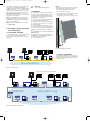
Fig. 3: Pin configuration of a TP/TX interface
10 Mbit/s F/O connection
10 MBit/s F/O ports (ST sockets) make it
possible to connect terminal devices or
independent network segments compliant
with the IEEE 802.3 10BASE-FL standard.
These ports support full and half duplex
operation.
State of delivery: half duplex.
Note: 10 Mbit/s ports are not ring ports.
100 Mbit/s F/O connection
100 MBit/s F/O ports (MTRJ or DSC sockets)
make it possible to connect terminal devices or independent network segments compliant with the IEEE 802.3 100BASE-FX standard. These ports support full and half
duplex operation.
State of delivery: full duplex.
V.24 interface (external management)
A serial interface for local connection of an
external management station (VT100 terminal or a PC with corresponding terminal
emulation) is available via the RJ11 socket
(V.24 interface). A link can thus be
established with the User Interface UI.
VT100 terminal settings:
– Speed:
9,600 Baud
– Data:
8 bit
– Stopbit:
1 bit
– Handshake: off
– Parity:
none
The socket casing is galvanically connected
to the lower panel of the device. The signal
lines are galvanically separated from the
operating voltage (60 V isolation voltage)
and the lower panel.
– Pin configuration of the V.24 interface:
– TX: Pin 3, RX: Pin 5
– CTS: Pin 1, RTS: Pin 6
– GND: Pin 4
– Pin 2: not used.
Factory settings: autonegotiation active
(except for the HIPER ring port).
The socket housings are electrically connected to the lower panel of the module. The
pin configuration complies with MDI-X.
Pin 6
Pin 5
Pin 4
Pin 3
Pin 2
Pin 1
Warning!
The MICE equipment is designed for
operation with SELV. Only safety
extra-low voltages to
IEC950/EN60950/VDE0805 may
therefore be connected to the
supply voltage connections and to
the indicator contact.
– Voltage supply: Redundant voltage supplies are supported. Both inputs are
decoupled. There is no load distribution.
With redundant supply, the power pack
supplies the MICE only with the higher
output voltage. The supply voltage is electrically isolated from the housing.
– Indicator contact:
The indicator contact is used to supervise
the functions of the MICE and thus
facilitates remote diagnosis.
Contact interrupt indicates the following
by means of a potential-free indicator
contact (relay contact, closed circuit):
– the failure of at least one of the two
supply voltages.
– a permanent fault in the MICE (internal
3,3 V DC voltage, supply voltage 1 or 2 <
18 V, ...).
– the faulty link status of at least one port.
The indication of the link state on the
MICE can be masked on a port-by-port
basis using the management software.
State of delivery: there is no link test.
– self test error
In addition the MICE in RM mode can indicate the following states:
– Ring monitoring is not possible, e. g.
during software initializing.
Note: In the case of the voltage supply
being routed without redundancy, the MICE
indicates the failure of a supply voltage. You
can prevent this message by feeding in the
supply voltage through both inputs.
+24 V (P1)
The V.24 interface baud rate can be
configured to 9,600 or 19,200 baud. The
factory default is 9,600 baud.
Fig. 2: 3-pin DIP switch
1.9 INTERFACES
10/100 MBit/s connection
10/100 Mbit ports (8-pin R45 sockets) allow
terminal equipment or independent network segments complying with the standards IEEE 802.3 100BASE-TX / 10BASE-T
to be connected. These ports support autonegotiation and the autopolarity function.
Pin 8
Pin 7
Pin 6
Pin 5
Pin 4
Pin 3
Pin 2
Pin 1
z
Pin
number
V.24
interface
Pin 1
Pin 2
Pin 3
Pin 4
Pin 5
Pin 6
CTS
not connected
TX
GND
RX
RTS
CTS
RTS
RX
TX
Clear To Send
Request To Send
Receive Data
Transmit Data
Fault
+24 V (P2)
Fig. 9: Pin configuration of 6pin terminal
block
Ground connection
The lower covering panel of the MICE
housing is grounded by the tophat rail and,
as an option, by the separate ground screw.
2. Configuration
2.1 LINE STRUCTURE
The MICE enables backbones in line
structures to be built up. Cascading takes
place via the ring ports.
Fig. 5: Pin configuration of the V.24
interface
Note: In chapter 6 „Technical data“ you
find the order number for the terminal
access cable which is to be ordered
separately.
2.2 REDUNDANT RING STRUCTURE
With the RM function (redundancy manager) of the MICE or with an MACH 3000 can
close the two ends of a line structured backbone to form a redundant ring.
6-pin terminal block
The supply voltage and the indicator
contact are connected via a 6pin terminal
block with screw locking mechanism.
5