1
Anl_MICEus_02 23.11.2001 10:57 Uhr Seite 8
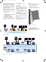
F/O line length 10 BASE-FL (example)
50/125 µm fiber (multimode)
62,5/125 µm fiber (multimode)
2,6000 m (8,530 ft) maximum
3,600 m (11,811 ft) maximum
F/O port 100BASE-FX
System attenuation
50/125 µm fiber (multimode)
62,5/125 µm fiber (multimode)
10/125 µm fiber (singlemode)
Wave length
8 dB
11 dB
16 dB
1300 nm
F/O line length (example)
50/125 µm fiber (multimode)
62,5/125 µm fiber (multimode)
10/125 µm fiber (singlemode)
5 km (16,400 ft) maximum
4 km (13,120 ft) maximum
30 km (98,420 ft) maximum
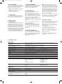
Interfaces
MS2108 - 2
MM2 - 2FLM4
MM2 - 4TX1
MM2 - 4FXM3
MM2 - 2FXM3 / 2TX1
MM2 - 2FXM2
MM2 - 2FXS2
(data of fiber: 3 dB/km, 400 MHz*km)
(data of fiber: 3.2 dB/km, 200 MHz*km)
(data of fiber: 1 dB/km, 800 MHz*km)
(data of fiber: 1 dB/km, 500 MHz*km)
(data of fiber: 0,4 dB/km)
V.24 port
Signaling relay
Power supply
2 FL-Ports
4 TP/TX-Ports
2 FX-Ports
2 FX-Ports
2 TX-Ports
2 FX-Ports
2 FX-Ports
external management
1 A, 24 V maximum
1 x green LED
1 x green LED
1 x green LED
1 x red LED
1 x green/yellow LED
1 x green LED
1 x green LED
1 x green LED
1 x green LED
1 x green LED
1 x green LED
2 x green LED
4 x green/yellow LED
P – Power, internal supply voltage present
P1 – Power 1, internal supply voltage 1 present
P2 – Power 2, internal supply voltage 2 present
FAULT – Failure, the indicator contact is open and indicates an error
RM – Redundancy Manager
L/D – Data/Link status
FDX – Full duplex
100 – 10/100 Mbit/s
AUTONEG – Autonegotiation
RING PORT – HIPER-Ring port
LED TEST – LED test
for service use
1 to 4 – The meaning depends on the setting of the display status.
(ST sockets, multimode, 10 MBit/s)
(RJ45 sockets,10/100 MBit/s)
(MTRJ sockets, multimode, 100 MBit/s)
(MTRJ sockets, multimode, 100 MBit/s) and
(RJ45 sockets, 10/100 MBit/s)
(DSC sockets, multimode, 100 MBit/s)
(DSC sockets, singlemode, 100 MBit/s)
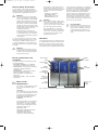
Displays
Device status
Display status
Port status
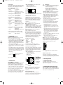
Controls
3-pole DIP switch
RM – activate redundancy manager functionality
Ring Port – defining HIPER-Ring ports
Scope of delivery
MICE MS2108 - 2 incl.
Terminal block for power supply and indicator contact
Labels, description and operating instructions
MICE manual on CD-ROM
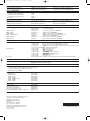
Order number
MS2108 - 2
MM2 - 2FLM4
MM2 - 4TX1
MM2 - 4FXM3
MM2 - 2FXM3 / 2TX1
MM2 - 2FXM2
MM2 - 2FXS2
943 717-001
943 734-001
943 722-001
943 721-001
943 720-001
943 718-001
943 719-001
Accessories
Basics manual
Terminal access cable
Rail Power Supply RPS 60
Rail Power Supply RPS 120
Network Management Software HiVision
039 624-001
943 301-001
943 662-001
943 662-011
943 471-100
Hirschmann Electronics GmbH & Co. KG
Automation and Network Solutions
Stuttgarter Straße 45-51
D-72654 Neckartenzlingen
Germany
Tel.: ++49 / 7127 / 14-1538
Fax: ++49 / 7127 / 14-1542
E-Mail: [email protected]
Internet: http://www.hirschmann.com
Printed in Germany
Subject to alterations
039649001021101000