1
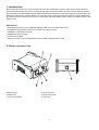
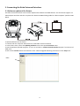
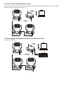
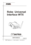
1 Table of contests 1. Introduction ................................................................................................................................................................ 3 2.Fixture exterior view .................................................................................................................................................... 3 3. Connecting the Robe Universal Interface ................................................................................................................... 4 3.1 Software update of the fixture ............................................................................................................................. 4 3.2 Connecting a DMX console to the Media Fusion .................................................................................................. 5 3.3 Fixtures status monitoring and setting ................................................................................................................. 6 3.4 Connecting the Robe Universal Interface to the fixtures link .............................................................................. 6 4. Installing the RDM‐network software ........................................................................................................................ 7 5. The main window of the RDM‐network software ...................................................................................................... 7 5.1 DMX network window .......................................................................................................................................... 8 5.2 Device groups window .......................................................................................................................................... 8 5.3 Parameter area .................................................................................................................................................... 9 5.3.1 Get parameters window ................................................................................................................................ 9 5.3.2 Set parameter window ................................................................................................................................ 10 6. Grouping fixtures ...................................................................................................................................................... 12 7. Scanning fixtures ....................................................................................................................................................... 13 8. Patching fixtures ...................................................................................................................................................... 14 9. Collecting parameters ............................................................................................................................................... 16 10. View sensor values ................................................................................................................................................. 19 11. Control of non‐display fixtures ............................................................................................................................... 20 12. Setting preferences ................................................................................................................................................. 21 13. Rescanning USB ports ............................................................................................................................................ 23 14. Selecting a port ....................................................................................................................................................... 23 15. Technical specifications .......................................................................................................................................... 23 16. Robe fixtures supporting RDM operation .............................................................................................................. 24 2 1. Introduction Robe Universal Interface is a multi‐functional tool box with 2 DMX ports and one USB 2.0 port. Robe Universal Interface communicates with a PC or Laptop via USB. Robe Universal Interface provides fixture software updates and with additional ROBE RDM‐network software provides RDM (Remote Device Management) functionality. The Robe Universal Interface supports RDM ‐ new control protocol featuring AutoPatch and Fixture Status Monitoring. The Robe Universal Interface can be used in combination with Robe Media Fusion software as DMX input from any DMX console. . Main features: ‐ Supported operating systems: Windows 98, ME, 2000, XP, Vista, Server 2003, Linux ‐ Brings RDM communication protocol into DMX 512 control systems ‐ USB/DMX or DMX/USB converter ‐ Rugged aluminium housing ‐ No extra PSU needed ‐ Galvanic isolation of 1kV between DMX Input andUSB / DMX Output and USB 2.Fixture exterior view 1‐DMX output 2‐ DMX input 3‐ Transmit data LED 4‐ Power on LED 5‐ Receive data LED 6‐ USB input 3 3. Connecting the Robe Universal Interface 3.1 Software update of the fixture The Robe Universal Interface can be used to upload new software into ROBE fixtures. The connection happens via USB computer interface and thus it replaces the "RS232 to DMX Flashing Cable for software update" (number 1305 0624). To upload software into the fixture. 1. Connect both the computer and the fixture to the Robe Universal Interface. 2. In the fixture menu, select the Updating Software item in the Special Functions menu. 3. Run the Software uploader program on your PC and select a Robe Universal Interface 1 option from the list of COM ports. 4. Click on the Connect button and continue in the software upgrade following instructions in the Help menu Robe 4 3.2 Connecting a DMX console to the Media Fusion The media Fusion is an intuitive media server environment that seamlessly integrates software and hardware for a professional quality, hassle‐free performance. To connect a DMX desk to Media Fusion via the Robe Universal Interface. 1. Connect the Robe Universal Interface to the computer running the Media Fusion. 2. Start (restart) the Media Fusion software. 3. In the Media Fusion, go into PreferencesÆDMXÆInterfaces and select Robe USB‐DMX in the DMX Interface field. 4. Connect a DMX desk into the DMX input of the Robe Universal Interface. The Robe Universal Interface now works as a DMX input device so you can patch your DMX Desk to DMX control Media Fusion. Don't forget to set up a DMX address of the Media Fusion in the PreferencesÆDMXÆPatch section. For detail description about installing and controlling the Media Fusion see the Media Fusion Software user manual. 5 3.3 Fixtures status monitoring and setting Connecting the Robe Universal Interface to the DMX link allows setting and monitoring of the fixtures via the RDM‐ network software running on the control PC. 3.4 Connecting the Robe Universal Interface to the fixtures link 1. DMX 512 connection 6 2. Ethernet connection with Art‐Net Note: If you use Ethernet for control of fixtures, never set the Ethernet/DMX option in the fixture (Fixture AddressÆEthernet SettingsÆSet Ethernet ModeÆEthernet/DMX), otherwise the RDM‐network software will not function properly. 4. Installing the RDMnetwork software 1. To install the Software Robe Universal Interface, please insert the RDM‐network installation flash drive into your computer’s USB 2.0 port. 2. Double‐click on the RDM‐network installation file (RDM‐network‐setup _100.exe, located in the directory RDM‐ network on the flash drive (there are versions for Windows and Linux). This will launch the RDM‐network installer. 3. Follow the on‐screen instructions. 4. Once the installation is complete, click “Finish”. The RDM‐network software is now ready to be used. 5. Run the RDM‐network by going to Start ‐> Programs ‐> Robe ‐> RDM‐network. 5. The main window of the RDMnetwork software 7 In the main window you can use a standard toolbar for quick access to commonly used commands and tools. The main window is organized into three main areas. 5.1 DMX network window The top left part of the main window shows the list of RDM talking fixtures found on the DMX link. Use the icons in the DMX network toolbar to sort the fixtures by a manufacturer/ a model ID or by a model ID and a manufacturer. The fixtures in the RDM‐network window can be displayed in two states: 1.On‐line state – the fixture names are displayed in a standard black colour , all changes made in the Set Parameter window can be promptly sent to the linked fixtures by using the button in the Get/Set Parameters toolbar. 2. Off‐line state – the fixture names are displayed in a red colour. This mode means that fixtures settings were loaded into RDM‐network software but have not been sent to the fixtures. You may work with displayed fixtures as with fixtures in on‐line mode, but the changes you have made will not be sent to the fixtures until you switched them to the on‐line state by using the button in a DMX Network toolbar 5.2 Device groups window The bottom part of the main window below a DMX network window shows groups of fixtures. The buttons in the Device Group toolbar have the following meaning: The button + adds a new group into existing list of groups. The button deletes a group or a fixture from the group. The button closes this window (if you wish to display the window again, check the option Groups in the View menu of the Menu bar) . 8 5.3 Parameter area The right side of the main window shows the list of Get/Set parameters of the fixture that has been selected in a DMX network window. Use and buttons in the Parametr area toolbar to toggle between Get and Set parameters window .The rest of buttons has the following meaning: The button + adds a new parameter into the list of parameters. The button in a Set/Get parameters toolbar closes this window (if you wish to display the window again, check the option Parameters in the View menu. The button sends values of selected items to the fixture (fixtures). The icon next to the item means that the parameter is not available. 5.3.1 Get parameters window The list of items ,which are displayed in the window, inform you about fixture behaviour. The button next to the item removes the item from the list of items. To put the item back to the list, click on the + button in the Get/Set parameter toolbar and select it from the list of items. RDM Protocol Version Major ‐ shows the first figure of RDM protocol version. RDM Protocol Version Minor – shows the second figure of RDM protocol version. Device Label ‐ shows the custom name of the fixture. Lamp Hours ‐ shows the accumulated total number of lamp hours. Lamp Strikes ‐ shows the accumulated total number of lamp strikes. Device Hours ‐ shows the accumulated total number of operation hours the fixture has been on. Display Invert ‐ shows he display orientation. Display Level ‐ shows the adjusted display intensity. Pan Invert ‐ shows pan control. Tilt Invert ‐ shows tilt control. Subdevices Count – shows number of controlled devices connected to the current fixture. Lamp State ‐ shows the lamp state (On/Off) Product Category Coarse ‐ shows the first figure of the product category Product Category Fine ‐ shows the second figure of the product category Software Version Label ‐ shows the software version of the main processor (IC1) in the fixture base. Software Version ID ‐ shows the figure of software version of the main processor (IC1) in the fixture base Lamp On Mode ‐ shows the way, how the fixture switches its lamp on automatically. DMX512 Start Address‐ shows the start channel (first channel which receives instructions from the controller). Device Model ID ‐ shows the figure of the fixture type (6‐spotlight, 4‐washlight). DMX 512 Footprint ‐ shows the number of control channels in a current DMX mode. DMX512 Current Personality ‐ shows a current DMX mode. DMX 512 Total of personalities ‐ shows the total number of DMX modes. Sensor Count ‐ shows the number of fixture sensors sending information to the Robe Universal Interface (e.g. temperature sensors). Manufacturer label ‐ shows the name of the fixture manufacturer. Device Model Description ‐ shows the name of the fixture. Identify Device ‐ determines whether the fixture runs in an identification mode. 9 5.3.2 Set parameter window The following items displayed in this window allow you to set a fixture behaviour . The button next to the item removes this item from the list of items. To put the item back to the list, click on the + button in the Get/Set parameter toolbar and select it from the list of items. DMX 512 Current Personality ‐ select desired DMX mode in the field . Identify Device – if the item is on, the fixture performs pan/tilt movement to identify it between another fixtures. DMX Start Address ‐ set desired start channel in the field. Device Label ‐ type the name of the fixture, max.32 characters. Device Reset ‐ the item starts a fixture reset. Lamp State ‐ the item enables to switch on/off the fixture lamp. Lamp On Mode ‐ select the way how to switch the lamp on automatically: Lamp off ‐ the lamp stays off until directly instructed to strike. Lamp on by DMX‐ the lamp strikes upon receiving a DMX 512 signal Lamp on at Power‐Up ‐ the lamp strikes automatically at power‐up . Lamp on after calibration‐ the lamp strikes after calibration or homing procedure Display Invert ‐ select desired display orientation. Display Level ‐ set desired display intensity (0‐min, 255‐max). Pan Invert ‐ the item inverts pan channel. Tilt Invert ‐ the item inverts tilt channel. Changing the fixture setting If you wish to change the fixture setting, select desired fixture in the DMX Network window, set fixture parameters in the Set parameter window, check the boxes on the left side and click on the icon in the Get/Set Parameters toolbar to send parameters to the fixture. Note: You can change setting all fixtures of selected manufacturer at a time. Select desired manufacturer in the DMX Network window, set fixture parameters in Set parameter window, check the boxes on the left side of items and click on the icon in the Get/Set Parameters toolbar to send adjusted parameters to all manufacturer´s fixtures. Saving current fixtures settings Current setting which have been sent to the fixtures can be saved to a file and then loaded into the fixtures at any time. 10 To save current setting. 1. Click on the Save Workspace item in the File menu on the Menu bar. 2. Select desired folder and type the name of the file and click on the OK button. Loading setting to the fixtures . Once saved fixtures settings can be loaded back into fixtures. To load fixtures settings. 1. Click on the Load Workspace item in the File menu on the Menu bar. 2. Select desired folder and the name of the file and click on the OK button. 3. The following window with information about uploading the fixtures will appear. 11 4. Click on the OK button and the loaded fixtures will appear in the DMX Network window. The fixture names are displayed in a red colour as they are in the off‐line mode, it means that they cannot effect the linked fixtures. 5. In order to switch the fixtures to the on‐line mode, click on the button in a DMX Network toolbar. All data from “xml” file will be sent to the fixtures. The fixture names are displayed in a standard black colour at this time. 6. Grouping fixtures The group of fixtures can be very useful when several fixtures have to have the same settings. You do not need to adjust fixture by fixture but you can set the same parameters for all fixtures in a group at once. To create a fixture group. 1. Click on the + button in the Device Groups toolbar and type the name of the group and click on the OK button. 12 2. The new empty group will appear in the Device Groups window. Move desired objects from the list of the fixtures in a DMX Network window to this group by drag& drop. You can move either individual fixtures or a group of selected fixtures (select them by clicking on desired fixtures while pushing the SHIFT key). If you select a manufacturer folder, you will move all fixtures included in this folder: To delete a group of fixtures (or individual fixture from a group), select desired group (fixture) and click on the button in the Device Groups toolbar. 7. Scanning fixtures To find fixtures linked to the Robe Universal Interface, select the Scan Devices in the Scan menu or click on the button ( button) in the Standard toolbar. The Scan network window appears. After scanning, found fixtures will appear in the list of fixtures in the DMX network window. There are two options in the Scan menu how to search linked fixtures: Scan Devices – finds all connected fixtures. Scan New Devices – finds new connected fixtures. Note: the new device presents a fixture which has been connected to a DMX link and switched on. If some fixture was unlinked and linked again without switching it off, the option Scan New Devices does not consider this fixture as a new device and will not find it on a DMX link. 13 8. Patching fixtures You can set the fixture starting DMX address either by using the Set Parameters window as was described earlier or by using the DMX patch option. This second way is more comfortable then former. To patch a fixture. 1. Select either the DMX patch option in the Tools menu or click with the right button of the mouse on the fixture (or a manufacturer icon) and select the Patch DMX Address option from the menu list. The DMX Patch window will appear. 2. Drag the fixture from the Devices To Patch window and drop it at a desired DMX start address in the Patch window. 14 By clicking with the right button of the mouse on a fixture icon (DMX start address) you can change the channel mode of the fixture. 3. Use the same process for all fixtures in list of fixtures. The properly assigned DMX channels are green, red channels indicate overlapping channels, yellow channels indicate that some channels will be missing. 4. To click on the Patch Devices button in the DMX patch toolbar to send these settings to the linked devices. 15 Next buttons in the DMX patch toolbar have the following functions: The Load Patch State button allows to load a file with fixture DMX start addresses you have specified in the past. Type the name of the file in the File Name field and click on the OK button. The Save Patch State button allows to save a current DMX addresses setting for usage in future. Type the name of the file in the File Name field and click on the OK button. The Auto Patch button starts automatic placing of DMX start addresses. The Patch By Devices button places current DMX addresses. The Reset Actual Patch button cancels current assigning of DMX start addresses and will move all fixtures to the Devices To Patch window. 9. Collecting parameters You can get information about fixtures either by using the Get Parameters window as was described above or by using the Collect Parameters option. 16 To collect parameters. 1.Select either the Collect Parameters option in the Tools menu or click with the right button of the mouse on the fixture (or a manufacturer icon) and select the Collect Parameters option from the menu list. The Collect Parameters window will appear. 2.Click with the right button of the mouse on the right panel of this window and the following list of items under Add New Parameter option will appear. Click on desired parameter and this one will appear in the right panel of the Collect Parameters window. By this way move desired parameters to the right panel of the Collect Parameters window. 17 3.Click on the Start Initial Collect button in the toolbar after having moved all desired items to the right panel of the window. The current loaded parameters will appear at each fixture line. The Start Collect button uses previously loaded parameters of the fixtures, so their displaying is faster but they maybe will not be so current like parameters obtained by the Start Initial Collect button. You can also remove or add an item to the Parameters table by clicking with the right button of the mouse on the field under a desired parameter. 18 10. View sensor values You can get information about temperature sensors (or other sensors which are installed in the fixture) and in this way you will be able to monitor the temperature conditions in the fixture. To view sensor values. 1.Select either the View Sensor Values option in the Tools menu or click with the right button of the mouse on the fixture (or a manufacturer icon) and select the View Sensor Values option from the menu list as shown below. The View Sensor Values window will appear. The Sensor Definition icon In this window, the are tables with individual temperature sensors and their values: Present Value – the current temperature of measuring point. Lowest Value – the minimum temperature of measuring point since the fixture has been fabricated. Highest Value– the maximum temperature of measuring point since the fixture has been fabricated. 19 If you click with the left button of the mouse on the Sensor Definition icon on the bottom right corner of each table, the window with detailed description of the fixture will appear. 11. Control of nondisplay fixtures You can also control fixtures without bilt‐on display. If such fixture is connected to the Robe Universal Interface, the option Remote LED display will appear in the menu at the fixture and it allows full control of the fixture. To control non‐display fixture. Click with the right button of the mouse on the fixture (or a manufacturer icon) and select the Remote LED display option from the menu list as shown below. 20 The Remote LED Display window will appear. Now you can fullly control the fixture using the UP, Down, Enter, Escape and Reset buttons. 12. Setting preferences Select the Preferences option from the Options menu and the following RDM‐Net Preferences window will appear. The Search menu shows following items: Normal search – standard speed of seeking fixtures on the data link. 21 Quick search – faster speed of seeking fixtures on the data link. Get devices descriptions on scan – gathers the fixtures parameters during searching fixtures on a DMX link. Use RDM broadcast for devices parameters setting – if this option is checked, RDM commands will be sent together to all fixtures without checking whether they were really proceeded by each fixture. If this option is off, RDM commands will be sent to the fixtures in sequence and their proceeding will be checked. In case that some RDM command will not be executed, the error message will appear in the top right corner of the RDM‐network window. Check desired option and click on the Accept button to save your setting. The next Icons and Colours menu buttons allow you to set an appearance of the RDM‐network window. The Logs menu allows to disable error messages which can occur during operations with fixtures if some fixtures parameters are not available. Check the box next to the “ignore unsupported commands” line if you do not want to display the error messages. Example: You work REDWash 3•192 (LED fixture)with ColorSpot 700E AT (discharge lamp) in the same group. If you run the Collect Parameters option on whole group, the LED fixture cannot send items which relate to the lamp and the error messages may apear ‐ it depends on the Logs menu setting: The Error icon is active If you click with the left button of the mouse on the Error icon, you can see the Command Statuses window with error messages: 22 13. Rescanning USB ports To rescan USB ports, select the Rescan Ports option from the Options menu. Use this option in case that the connection between the Robe Universal Interface and a PC was lost (it may come on if your laptop has gone to a “sleep mode”). 14. Selecting a port In future the option Port in the Options menu will allow to select desired USB port (Robe Universal Interface) in case that more than one Robe Universal Interface is connected to the PC. 15. Technical specifications • • • DMX data I/O: 2x locking 5-pin XLR USB : 1x USB 2.0 connector (series B) Weight: 0.3 kg Dimensions (mm) Included items: • 1x Robe Universal Interface • 1x Flash drive with the RDM‐network software and the user manual • 1x USB cable 23 16. Robe fixtures supporting RDM operation There is a list of ROBE fixtures which offer Remote Device Management but software update or hardware upgrade has to be performed in fixtures which do not cover latest software/hardware configuration. Robe fixtures RDM ready: Anolis fixtures RDM Ready: ColorWash 2500E AT ArcPad Xtreme Colorspot 700E AT ArcPad 48 Integral ColorWash 700E AT ArcSource 96 Integral ColorWash 750 AT Tungsten DigitalSpot 3000 DT DigitalSpot 7000 DT REDWash 3•192 REDMix 3 •192 Robin 300E Spot Robin 300E Wash Robin 300E Beam Robin 300 Plasma Spot Robin 300Plasma Wash ColorBeam 700E AT City Skape Xtreme CitySkape 48 CitySource 96 Fixtures, which need a hardware upgrade (manually) of processors IC1MB and IC1DS and a software update. Unit Software update Hardware upgrade needed needed for processor: if processor version is less than: IC1MB IC1DS ColorWash 250 AT ‐ 2.0 ‐ ColorWash 575 AT ‐ 2.0 ‐ ColorWash 575 AT Zoom ‐ 2.0 ‐ ColorWash 575E AT IC2DS 2.0 2.0 ColorWash 575E AT Zoom IC2DS 2.0 2.0 Colorspot 1200 AT (IC1DS)*, IC2DS 5.0 5.1 (5.0)* Colorspot 1200E AT (IC1DS)*, IC2DS 5.0 5.1 (5.0)* ColorWash 1200E AT IC2DS 3.0 3.0 Colorspot 2500E AT (IC1DS)*, IC2DS 3.0 3.1 (3.0)* IC1R ColorMix 575 AT ‐ 2.0 ‐ *If the version of IC1 DS is greater or equal to a number stated in brackets, changing of IC1DS is not needed. Its software update has to be performed only. Fixtures,which need a hardware upgrade (manually) of processor IC1MB or IC2. Unit Hardware upgrade needed if processor version is less than: IC1MB IC2 IC1DS IC2DS Colorspot 575E AT 3.0** ‐ 1.6** 1.6** ColorSpot 575 AT 3.0 ‐ ‐ ‐ Colorspot 250 AT 3.0 ‐ ‐ ‐ Colorspot 170 AT 2.0 ‐ ‐ ‐ ColorMix 250 AT ‐ 2.0 ‐ ‐ ColorMix 240 AT ‐ 2.0 ‐ ‐ 24 ColorMix 150 AT Wash ‐ 2.0 ‐ ‐ **Only Colorspot 575E AT needs latest version of IC1MB, IC1DS and IC2DS . To verify if the fixture with LCD graphic display supports RDM operation, go to the fixture´s menu “Fixture Information—>Product IDs” and try to find the item “RDM UID”. To verify if the fixture with LED display supports RDM operation, go to the fixture´s menu “SPEC” and try to find the items “rdML” and “rdMH”. Version 1.6 Specifications are subject to change without notice. January 18, 2010. 25 26