1
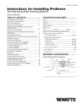
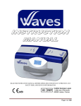
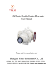
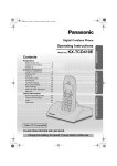
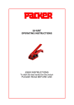
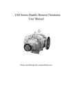
V-SENSOR AIR PRESSURE AIR VOLUME
•
•
•
•
•
•
•
•
•
•
•
•
•
Ultra low pressure and volume measurement
Traceable Calibration Certificate is included
High accuracy and repeatability
Linear pressure or air volume output
Both measurement and PID control output
Two modbus for monitoring and remote display
One alarm relay, buzzer and LED indicators
Auto Zero and overload protection is standard
Operator keyboard display for all functions
Two Modbus rtu, 0..10V and 4..20mA outputs
IP65 enclosure with easy mount wall bracket
24 month warranty
30 Years field application experience
V-SENSOR Wall Mount with Keyboard and LED display
GENERAL
The V-Sensor is a wall mount ultra low pressure transmitter which
provides 0..10V and 4..20mA as well as Modbus communication
over the selected range . The display can be adjusted via the
keyboard to show the measured value in Pa, hPa, kPa, m/s, l/s,
m3/s, m3/h and ACR (air change rate).
KEYBOARD DISPLAY
A combined keyboard and LED Display is fitted into the lid and is
connected to the V-Sensor board with a plug-in ribbon cable. All
parameters can be accessed via the key pad. The display can also
be programmed to switch off after a time and by touching a key to
light up again. Normally it is always on.
A PID control output can be selected, but still having one output for
monitoring the pressure or volume.
PARAMETER CONFIGURATION
The duct width and height can be entered as well as the density and
(mf) magnification (K) factors to scale Fan Inlet Rings, Flowgrids,
Veloprobes, Oval Flowprobes, Venturis or any other velocity
pressure producing probes. The volume can be linearized over 8
points to provide extremely high accuracy in measurement.
The pressure ranges can be adjusted via the keyboard, but the base
range is factory calibrated and certified i.e. 10, 25, 50, 100, 250 and
going up to 7500 Pa. All ranges can be adjusted to +/- ie. -/+25Pa.
Power supply 24Vdc/ac non-isolated or 24,110 and 230Vac isolated
are available as standard.
CMR TRANSDUCER
The transducer is manufactured by
CMR with high precision engineered
components. The principle is the
measurement of the displacement of
the diaphragm by means of a push and
pull variable reluctance circuit which is
not affected by humidity and hence it
can be used in any industrial or
commercial environment. There are no
mechanical connections to any of the
sensing coils and the diaphragm.
CMR Transducer
Extremely low pressures can be measured with excellent repeatability and minimal hysteresis. The diaphragm displacement is so small
that no air volume is required to measure the air pressure which
means measurement tubing can be connected in excess of 200m
throughout the building without losing accuracy or measurement
speed.
The zero drift is minimized by the
measuring copper coils which are
matched to provide excellent self
compensation. One coil measures
positive and the other negative drift
and therefore balances any
excessive drift between two
tolerance limits in its life cycle. The
CMR Transducer has a proven
field track record of over 30 years.
All CMR Sensors are temperature
compensated in a computerised
climate chamber.
The auto zero function is built in, which is of great advantage at very
low velocity pressure measurement i.e. 0.3 Pa to have an accurate
base point at all times. The auto zero can be turned off where it is not
required.
The overload protection can be switched on and is ideal to protect
the low pressure diaphragm. It is active whenever the sensor is
powered up.
One of the outputs can be configured to be a PID control to drive fan
inverters or modulating dampers and the other can be used for the
actual pressure or air volume measurement for the BMS or PLC
system. The set point can be sent from the BMS via modbus.
The signals can be individually smoothed. The control output can be
fast but the measurement output can be dampened.
A calibration mode can be selected so that all of the parameters
remain the same as commissioned and only the base sensor shall
be calibrated and displayed in Pa.
MODBUS rtu COMMUNICATION
The modbus communication can be used to read and write all
parameters by the remote Host which can be the BMS , PLC or PC.
CMR Climate Chamber
CMR CONTROLS
Ltd
Precision Air Pressure and Volume Sensors
Copyright © 2011-2012-2013-2014
The range can be changed from -10 Pa to 30 Pa or -20 to 120 Pa.
The output signals can be changed to i.e. 2..10V, 1..5V or 5..19mA.
The V-Sensor has a configurable Volt Free alarm output relay.
REMOTE ALARM DISPLAY
A remote display DIS110 without alarm or
DIS125 with alarm and mute button can be
connected via Modbus if the modbus is not
used for the BMS. The alarm button has
green and red Led light rings to show
healthy or alarm status. A buzzer is also
fitted. A separate power supply can be
wired to the display.
Remote Display Plate
22 Repton Court Repton Close
Basildon Essex SS13 1LN GB
www.cmr-controls.com
web
All rights reserved
Phone +44 (0) 1268 287222
Fax
+44 (0) 1268 287099
mail [email protected]
The information is subject to change without notice
Page 1
®
CMR
Issue V-GB-04-2
V-SENSOR
PRESSURE APPLICATIONS
ROOM PRESSURE MEASUREMENT WITH CMR V-SENSORS
Typical Clean Room Pressure Monitoring and Alarming
V-SENSOR
V-SENSOR
V-SENSOR
45.0
30.0
15.0
Tubes + Fittings
Pa
+ -
Pa
+ -
DIS 110 Display
Pa
+ CMR Blue Tube
CMR Blue Tube
CMR Red Tube
CMR Red Tube
Air Probe
Ceiling Air Probe
Reference
CMR Red Tube
AIR Probe
AIR Probe
30.0
45.0
DIS 110 Display
ROOM 2
ROOM 1
DIS 125 Display
15.0
DIS 125 Display
with green-red
LED ring in
Mute Button
DIS 110 Display LED 225 Alarm
Display
ROOM 3
LED 225 Display
Air Probe Plate
The above schematic shows a typical clean room. The room
pressures are measured in cascades starting in Room 3 from a
reference such as a plant room or any other stable location, then
measuring across to room 2 and finally across to Room 1.
Each room has an air probe plate fitted to the ceiling. The air probes
are connected to the V-Sensors with red and blue CMR PVC Tubing.
The CMR PVC tubing can be run up to 200m from the room to the
P-Sensor without losing accuracy of the measurement.
Remote LED display plates are fitted for the operators to see the
actual room pressure in Room 1 and 2. Room 2 has also a local
illuminated alarm green and red led built as ring into the mute button
and a buzzer. Room 3 has only a modbus alarm led indicator plate.
The V-Sensor is a true Low Differential Air Pressure Transmitter and
can be used for static pressure, vacuum pressure and differential
pressure measurements in positive or negative areas.
The operator keyboard with LED display is fitted into the lid as
standard and shall display the actual pressure. All parameters can
be adjusted without opening the lid.
The Pressure measurement can be transmitted via modbus rtu or
analogue signals 0..10V or 4..20mA to the SCADA, BMS or
industrial PLC systems for long term monitoring.
All future calibration can be done using the calibration mode.
Calibration Certificates traceable to National and International
Standards ( UKAS) are supplied as standard with all V- Sensors.
TYPICAL PRESSURE APPLICATIONS
Measurement
and PID control
750 Pa
+ -
-250 Pa
+ -
Static Positive Pressure
Static Negative Pressure
15 Pa
+ -
5.0 Pa
Measurement
and PID control
Room Pressure
+ -
Measurement
and PID control
Measurement
and PID control
Ltd
Precision Air Pressure and Volume Sensors
-540 Pa
Total Extract Pressure
+ -
Measurement
and PID control
Filter Pressure
12.8 Pa
+ -
Velocity Pressure
Phone +44 (0) 1268 287222
Fax
+44 (0) 1268 287099
mail [email protected]
The information is subject to change without notice
Page 2
Measurement
and PID control
+ -
450 Pa
Measurement
and PID control
22 Repton Court Repton Close
Basildon Essex SS13 1LN GB
www.cmr-controls.com
web
All rights reserved
920 Pa
+ -
Total Supply Pressure
Differential Room Pressure
CMR CONTROLS
Copyright © 2011-2012-2013-2014
Measurement
and PID control
®
CMR
Issue V-GB-04-2
V-SENSOR
AIR VOLUME APPLICATIONS
VELOCITY PRESSURE AND AIR VOLUME MEASUREMENT WITH CMR V-SENSORS
Typical air volume measurement in air distribution systems
Exhaust Air
Fresh Air
V-Sensor
V-Sensor
Silencer
Oval Flowprobe
FGG Flowgrid
V-Sensor
Silencer
CMR Veloprobes
V-sensor
V-Sensor
Veloprobe
S
E
VVM Venturi
Duct probe
Duct Probes
Supply Air
Extract Air
V-Sensor
V-Sensor
Venturi
V-Sensor
V-Sensor
V-Sensor
Flowgrid
E1
S1
E2
S2
S3
Veloprobe
Oval Flowprobe
PVC Tube Fittings
The CMR V-Sensor is an ultra low high precision Velocity Pressure
Transmitter which has been designed to accurately measure air
volumes in Ventilation Ducts . The built in Square Root Extraction
and Magnification Factor Scaling makes the V-Sensor an extremely
versatile measurement instrument.
The V-Sensor is used for monitoring and also controlling Volume
Flow in Commercial or Process Applications and is designed to be
connected to any CMR Veloprobes, Duct Probes, Flowgrids,
Venturis and Fan Inlet Rings. It can also be used with any existing or
custom made duct Flow Measurement Device.
It can display the actual volume in m3/s. Other Units such as m3/h,
litres/s or ACR ( Air change rate) can be selected via the keyboard.
Any imperial measurement units i.e. CFM are available on request .
The measured values can be transmitted to remote display plates,
SCADA, BMS control systems or industrial PLCs through the output
signals of 0..10V, 4...20mA, modbus 1 and 2.
The CMR PVC tubing can be run up to 200m from the sensing station
to the V-Sensor without losing the accuracy of the measurement.
Calibration Certificates traceable to National and International
Standards (UKAS) are supplied with all V-Sensors.
TYPICAL CMR AIR VOLUME MEASUREMENT APPLICATIONS
Measurement
and PID control
11.5 m/s
Measurement
and PID control
+-
CMR Duct Probes
Measurement
and PID control
CMR Veloprobes
15.3 m3/s
Measurement
and PID control
+-
CMR FGG Flowgrid
0.3 m3/s
+-
Silencer Oval Flowprobe
CMR CONTROLS
Ltd
Precision Air Pressure and Volume Sensors
Copyright © 2011-2012-2013-2014
3.5 m3/s
+-
Measurement
and PID control
CMR Orifice Plate
Measurement
and PID control
0.7 m3/s
+-
Round Flowprobe
22 Repton Court Repton Close
Basildon Essex SS13 1LN GB
www.cmr-controls.com
web
All rights reserved
35.1 m/s
+-
Measurement
and PID control
CMR Venturi Flow
Measurement
and PID control
20.1 m/s
+-
CMR Fan Inlet Ring
Phone +44 (0) 1268 287222
Fax
+44 (0) 1268 287099
mail [email protected]
The information is subject to change without notice
Page 3
1.2 m3/s
+-
®
CMR
Issue V-GB-04-2
V-SENSOR VELOPROBE MEASUREMENT
GENERAL
The drawing shows a typical application for
CMR Veloprobes and V-Sensors.
V-Sensor
The supply air duct can either be fitted with one
central Veloprobe or individual Veloprobes on
each of its branches.
Exhaust Air
Fresh Air
In many
cases, the positions of the
Veloprobes are very much dictated by the
design of the building. The CMR Veloprobe can
be fitted in almost any position in order to
provide accurate measurements.
V-Sensor
S
V-Sensor
In a single supply and extract duct application,
the V-Sensor measures the building's actual
total supply and return volumes. As both
V-Sensors are calibrated to provide a linear air
volume signal, tracking of supply and extract
air is now made easy.
E
The duct height, width or diameter, density and
magnification ( 'K' factors) can be entered in
the V-Sensor via the keyboard very easily and
only the measurement range for 0..10V or
4..20mA must be given to the BMS at final
commissioning.
V-Sensor
V-Sensor
E1
For multiple duct applications, the total supply
and extract air volume is derived by adding all
air volumes from the individual ducts.
Supply Air
Extract Air
Example of Volume adding:
V-Sensor
V-Sensor
V-Sensor
S3
S2
S1
E2
V-sensor
S = E ± an offset for positive or negative building pressure
S1 + S2 + S3 = E1 + E2 ± offset or S = E1 + E2 ± offset - etc
V -Sensor - scaling in m/s only.
V-Sensor - scaling in m3/s - m3/h - l/s - ACR air change rate
Adjust the Impact Veloprobe (red) to face the Airflow and and
adjust the Static Veloprobe (blue) to approx. 180º away from the
airflow.
Adjust the Impact Veloprobe (red) to face the Airflow and and adjust
the Static Veloprobe (blue) to approx. 180º away from the airflow.
Scaling of the duct height and width is done in the BMS
Use the keyboard and adjust the display to m/s. Adjust the height
and width to 1 and adjust the (mf) to 2.000. Press the very left hand
key briefly and the sensor range is displayed for a short time,
which is the range at 10V in m/s. If the range of the sensor is 100Pa
then it should display 9.128 m/s.
Take a Pitot Tube reading in the duct and if the velocity is not equal
to the display then adjust the magnification factor until it is equal
then press the range key again to get the new range in m/s.
Scaling the range for the BMS
Use the keyboard and enter the duct height and width or simply
enter the width of a round duct and keep the height at 0. Adjust the
magnification factor (mf) to 2.000. Use the display key and select
m3/s, m3/h, l/s or ACR (Air Change Rate) and adjust the decimal
places. When pressing the left hand key the sensor range shall be
displayed in the selected units at 10V. Take a Pitot Tube reading in
the duct and if the volume is not equal to the display then adjust the
magnification factor until it is equal then press the range key again
to get the new range.
V-Sensor air volume measurement with Veloprobes in Duct
V-Sensor
Veloprobes
CMR CONTROLS
Ltd
Precision Air Pressure and Volume Sensors
Copyright © 2011-2012-2013-2014
22 Repton Court Repton Close
Basildon Essex SS13 1LN GB
www.cmr-controls.com
web
All rights reserved
Phone +44 (0) 1268 287222
Fax
+44 (0) 1268 287099
mail [email protected]
The information is subject to change without notice
Page 4
®
CMR
Issue V-GB-04-2
V-SENSOR
KEYBOARD FUNCTIONS
FUNCTIONS (Use Operator Manual for full Instructions)
The V-Sensor LED-Keyboard has been designed to simplify
installation and commissioning. The only time the lid must be
opened is for wiring during installation. Thereafter every control
function can be accessed via the keyboard, even the calibration can
be carried out utilising this functionality.
V-SENSOR STANDARD LED KEYBOARD
5 Digit
Red LED
Display
Green/Red
Alarm
ZERO LEGEND
LED’s
Label
Key
ZERO KEY
When pressing the zero key for 1 seconds, the V-Sensor shall
perform a zero which means the pressure is taken off the sensor
internally and the diaphragm is relaxed to zero.
>0<
PASSWORD
The keyboard can be password protected so that only the display
can be operated, but no adjustments can be made.
RANGE KEY
Pressing the range key very quickly once will display the sensor
range i.e. if it shows 100, this means the range of the sensor has
been configured to 0-100Pa for 10V/20mA output. By pressing the
range key for 1 seconds it enters the configuration menu:
1.5
1-254 (0 Denotes Modbus Display)
on - off
i.e. + 25
i.e. - 25
1(on) 0(off)
d or o
I or E
1-99 h
0-3
OUTPUT KEY
Pressing the output key very quickly once will display the sensor
output configuration i.e. lin or root, which means the sensor
measures pressure or airflow. By pressing the output key for 1
seconds the configuration menu can be reached:
0-99
linear pressure
square root
F, L or Fac
0-99.99
0-9999mm
0-9999mm
0 -9.99kg/m3
0-9999m3
0- 99.99%
UP - DOWN KEY
The up and down keys are used to select the various parameters
0 or 1
V-SENSOR CIRCUIT BOARD
DISPLAY KEY
Pressing the display key very quickly once will display the
measurement units. i.e. Pa, hPa, kPa etc, and is the units the sensor
has been configured to i.e. Pa. By pressing the display key for 1
seconds it enters the configuration menu:
on
12345678
D8 D9
SW2
J1
Program
7 8 9 10
JP4 SLOW
Analogue Display
Precision Air Pressure and Volume Sensors
22 Repton Court Repton Close
Basildon Essex SS13 1LN GB
www.cmr-controls.com
web
All rights reserved
Relay
141516
D0
D1
MODBUS 1
GND
4-20mA
GND
0-10V
Phone +44 (0) 1268 287222
Fax
+44 (0) 1268 287099
mail [email protected]
The information is subject to change without notice
Page 5
F1
NO C NC
J6
Led-Key
P1
For Power
Supply
refer to
product
Label
11 13
MODBUS 2
J7
Ltd
GND /N/0V
19-33 Vdc
D0
D1
GND
ZERO
P2
1 2 3 4 5 6
SW1
on
CMR CONTROLS
Copyright © 2011-2012-2013-2014
J4
SW5
Coil
Connector
GND
Display Smoothing
0-99
Pascals
hecta Pascals
kPa
metres per second
litres per second
cubic metres per second
cubic metres per hour
Air Change Rate per hour
Decimal Place
0- 4
Display polarity (+)
Display polarity (-)
Display Activation
1 or t
Leading Zero Blanking 1 - 4
SPAN
J3
123456
Sd
Pa
hpa
3pa
nnps
Ips
nn3s
nn3h
acr
dp
pos
neg
Led
L2b
24Vdc non isolated
24V /110V or 230Vac isolated
OUTPUT SIGNAL
0-10V and 4-20mA are also available on J7.
4-20mA
+15Vdc
0-10V
Output Smoothing
Output mode
Output mode
Output scaling
Mag Factor
Duct width
Duct height
Air Density Factor
Room Size
Small Value Shut off
Output Re-Scaling
Bi-Directional Flow
UP & DOWN
Selection
Keys
ALARM KEY
Pressing the alarm key quickly shall mute the alarm as the
V-Sensor has an alarm buzzer built in.
By pressing the alarm key for 1 seconds it enters the configuration
menu:
L
Low Alarm
H
High Alarm
t
Alarm timer 1
0-999
t.
Alarm timer 2
0-999
u.
Units
dU (Display Units) or Per (%)
af
Alarm Function
0-2
Sr Self Reset
0-1
rb Remote Buzzer
-, 0, 1 or P
rA Remote Alarm Indication -, 0, F or LH
rt
Re-alarm timer
0-999 minutes
tU Alarm timer units
s or h
Green flashing is heart beat
So
Lin
root
e
F
_
I
d
r
s
o
bFl
RANGE OUTPUT DISPLAY ALARM
Key
Key
Key
Key
Red Over or Under Load
S
Software Version
Ad
Network Address
AZ
Auto Zero
P
Positive Range
n
Negative Range
Opp Over Pressure
F
Zero Offset
t
Set Point
Sn
Modbus smoothing
Adj
Internal / External
Azt
Auto Zero time interval
FF
Modbus float format
®
CMR
Issue V-GB-04-2
V-SENSOR
ORDER DESCRIPTION
GENERAL
CMR manufactures the V-Sensors to suit many low pressure and
volume measurement applications. Because of the variety of
pressure ranges, output signals and power supplies it has been
necessary to design an easy to use selection table for anybody to
make up a V-Sensor specification to satisfy a requirement. On
the V-Sensor Selection Table you will find all specifications
available with the associated ordering code.
V- SENSOR BASE PART NUMBER
The V-Sensor Part Number starts with a base part number of the
type of sensor. Code ‘24’ which is a V-Sensor in a standard ABS
enclosure.
The Part Number therefore starts with ‘24’.
V-SENSOR ISSUE No
The V-Sensor will have a version number to identify the model.
The Code is ‘1 for version 1’.
The Part Number extends to ‘241’
TUBE CONNECTORS
6 mm barbed nipples to fit CMR PVC Tube are fitted as standard
into the ABS box. They have the Code ‘A’.
4 mm barbed nipples to suit the CMR SiliconeTube are also
available as Code ‘B’.
The example has 6 mm barbed nipples which is standard.
The Part Number therefore extends to ’ 241A ’.
NEGATIVE PRESSURE RANGE
The Negative Range is specified as (-). If the application requires
to measure a negative pressure against a reference, i.e. a room
has to be at negative pressure compared with the corridor then
the room has to be connected to the Red or (+) nipple. The blue (-)
nipple shall be connected to the reference in this case the corridor.
The negative room pressure shall suck on the red (+) nipple and
the V-Sensor produces an output signal equivalent of the negative
pressure measured.
In the Example we have chosen - 25 which has the Code '0025' .
The Part Number extends to ‘241A0025’.
LABEL UNITS
As the V-Sensor has a fixed label next to the LED display, i.e. Pa,
kPa, hPa, mB etc. It is necessary to specify the label when
selecting the part number as this is all part of the validation of the
instrument.
In the example Code’P’ for Pa was selected.
The Part Number extends to ‘241A0025P0025P’
OUTPUT SIGNAL
The Industry Standards for Output Signals are 0-10V or 4-20mA,
but other signals can be adjusted via the keyboard by the operator.
If 0-10V is the Output Signal for -25 Pa to + 25 Pa then 5 V is 0
Pa. From 5V to 0V the V-Sensor measures from 0 Pa to - 25 Pa
i.e.(-)12.5 Pa would be 2.5V.
From 5V to 10V the V-Sensor would measure positive Pressure
from 0 Pa to + 25 Pa i.e. +12.5 Pa would be 7.5V.
It is standard to use equal ranges -25 Pa to +25 Pa rather than -25
Pa to + 50 Pa but the V-Sensor can be adjusted via the keyboard
to provide this off-set.
In the Example, we have selected Dual (0-10V & 4-20mA) which
has the Code '1'.
The Part Number extends to ‘241A0025P0025P1’
POWER SUPPLY
CMR can supply 24Vdc/24Vac Non-Isolated which does not have
an isolation transformer, and is also suitable for 3-Wire
connection. Most common is the 24Vac Isolated. 110Vac and
230Vac are less used, but also selectable. In the example we have
selected 24Vac isolated which has the Code '3'.
The Part Number extends to ’241A0025P0025P13’.
FINAL PART NUMBER
The Part Number to order is ‘241A0025P0025P13’
Now try and select your own V-Sensor using the V-Sensor
Order Selection Table.
If the V-Sensor must only measure in the positive Range i.e 0-25
then the Negative Range will always be selected as 0 and the
Code is always ‘0000’.
PRESSURE UNITS
The negative pressure and the positive pressure range must be
expressed in units i.e. Pa or kPa. The CMR transducers are in
Pascals (Pa) as standard.
In the example Pa was selected with Code ‘P’.
The Part Number extends ‘241A0025P’
POSITIVE PRESSURE RANGE
To measure Positive Pressure against a reference it is necessary
to select a positive range i.e. +25. The Code is ‘0025’ This means
the V-Sensor selected above can measure from - 25 Pa to 0
and from 0 to +25 Pa. The output Voltage would therefore be 5V or
12mA at 0 Pa.
The Part Number extends to ’241A0025P0025’
CMR CONTROLS
Ltd
Precision Air Pressure and Volume Sensors
Copyright © 2011-2012-2013-2014
22 Repton Court Repton Close
Basildon Essex SS13 1LN GB
www.cmr-controls.com
web
All rights reserved
Phone +44 (0) 1268 287222
Fax
+44 (0) 1268 287099
mail [email protected]
The information is subject to change without notice
Page 6
®
CMR
Issue V-GB-04-2
V-SENSOR
ORDER SELECTION TABLE
The Selection Table has been prepared to make ordering easy. Each column contains a number of different options which are available and a
Part Number can be established by you depending on a specific requirement.
The Example Part Number 241A0025P0025P13 which is printed above the Selection Table and identified as being a V-Sensor with ABS
enclosure, having an LED Display and Keyboard, with an issue No 1, with 6mm barbed tube connectors, a Negative Pressure Range of -25,
Range Units in Pa (Pascals) and a Positive Range of +25, labelled in Pa (Pascals) with Dual Output Signals of 0-10V & 4-20mA,which would
mean in this case
0 Pa is 5V & 12mA. The Power Supply is 24Vac.
The V-Sensor would be supplied with a 5 digit LED-Keyboard / Display mounted internally into the Lid and the Measured Units are Pa
(Pascals). The Decimal Point is user adjusted to 1 on the keyboard which indicates from -25.0 Pa to +25.0 Pa It comes with a traceable
Calibration Certificate to national and international Standards (UKAS).
24
1
A
0025
P
0025
P
1
V-Sensor
Issue
Nipple
Negative
Range
Positive
Label
Output
Power
Part No.
Base = 24
No
Issue = 1
Size
6mm = A
Range
Signal
Supply
0000
Units
Pa = P
4mm = B
0010
0010
kPa = K
0025
0025
mB = B
110 Vac = 4
0030
0030
hPA = H
230 Vac = 5
0050
0050
m/s = V
0060
0060
m3/s = Q
0100
0100
m3/h = M
0120
0120
l/s = L
0125
0125
ACR = A
0150
0150
0200
0200
0250
0250
0500
0500
0750
0750
1000
1000
1250
1250
1500
1500
2000
2000
2500
2500
5000
5000
7500
7500
0000
Range
Units
Pa = P
3
Dual = 1
24Vdc = 2
24 Vac = 3
HOW TO ORDER
EXAMPLE
A wall mount pressure transmitter is required of the Type V-Sensor
An LED complete with Keyboard is required as standard with an issue No 1.
The tube connections must be 6mm for CMR PVC Tube
The negative pressure range must be -100 Pa
The measured units must be in Pascals (Pa)
The positive pressure range must be +100Pa
The units on the LED display must in Pa as well as on the Product label.
The output signal must be Dual (0-10V & 4-20mA)
The power supply must be 24Vdc non-isolated
Call CMR for assistance at any time
The part Number for this V-Sensor is 24 1 A 0100 P 0100 P 1 2
CMR CONTROLS
Ltd
Precision Air Pressure and Volume Sensors
Copyright © 2011-2012-2013-2014
22 Repton Court Repton Close
Basildon Essex SS13 1LN GB
www.cmr-controls.com
web
All rights reserved
Phone +44 (0) 1268 287222
Fax
+44 (0) 1268 287099
mail [email protected]
The information is subject to change without notice
Page 7
®
CMR
Issue V-GB-04-2
V-SENSOR
TECHNICAL SPECIFICATION
Measurement Range
Any Range from 0-25Pa or -/+25Pa up to 0-7500Pa or -/+7500Pa
Overload Capacity
Ranges 25Pa - 150Pa up to max 1200Pa if over pressure protection is off.
Ranges from 200Pa - 7500Pa up to max 10 times of range if over pressure protection is off.
Media
Non corrosive gases such as Air, N2, O2, Co2, N2O and inert gases
Diaphragm Unit
Beryllium Copper suitable for high concentration of Formaldehyde - Stainless Steel on request.
AC Power Supplies
24 Vac 50/60Hz 198mA. Internal Fuse 300mA Auto-Reset.
Transformer Isolated
110Vac 50/60Hz
40mA. Fuse 315mA Wickmann.
230Vac 50/60Hz
20mA. Fuse 315mA Wickmann.
DC Power Supplies
24 Vdc (19 to 31Vdc) smoothed 118mA Internal Fuse 300mA Auto-Reset.
Voltage Output Signal
0-10V (0 to100% of Range) RL = 5kOhm min.
Other output signals (e.g. 2-10V) or PID loop control is programmable via the keyboard.
Current Output Signal
4-20mA (0 to100% of Range) RL = 500 Ohm max. (0-20mA) or PID control is programmable via keyboard
Relay Output 1A 24Vdc
One Alarm changer over volt free contact is user programmable
2 x Modbus rtu Connection
2 x Output Signal, Alarm Status, Alarm Thresholds and Alarm Timers are all readable as Modbus rtu
Commands. Modbus register assignments to read and write are available in user manual.
Hysteresis/Repeatability
0.1% Typical of Full Scale.
Linearity (Accuracy)
+/- 0.25% of Full scale = > 100 Pa and 0.25Pa < 100Pa.
Zero Drift
0.05%K (+10°C to +50°C) - Automatically corrected to 0.0 if Auto-Zero function is enabled.
Operating Temperature
-10°C to +70°C.
Mounting Position
Vertical.
Weight
0.6 kg in ABS Housing.
Electrical Connections
ABS Housing: 1 x M20 Gland and 1 x M12 Gland and internal removable Screw Terminals.
Air Tube Connections
ABS Housing: Positive and Negative Pressure Barbed Nipple 6mm OD x 15mm long for CMR PVC Tube
Enclosure
Plastic (ABS) Light Grey (RAL7035) - Protection IP65.
Conformity
EN61326-1 EMC - EN61010-1 SAFETY.
Calibration Certificate
Supplied with Certificate traceable to national and international Standards (UKAS).
Alternatively Barbed Nipple 4mm OD x 15mm long for silicone tube on special request.
V-SENSOR DIMENSIONS AND CONNECTIONS
122mm
Copyright © 2011-2012-2013-2014
6
J2
Modbus
rtu (1)
24Vdc
11 13
GND/0V
GND
4-20mA
5
D1
3 4
D0
2
GND
1
0-10V
24Vac
GND / 0V
4-20mA
3 or 4 Wire Connection
GND 2 is the same as
GND 11
4 Wire Connection
22 Repton Court Repton Close
Basildon Essex SS13 1LN GB
www.cmr-controls.com
web
All rights reserved
Modbus
rtu (1)
230Vac
11 13
0Vac
GND
6
4 Wire Connection
Phone +44 (0) 1268 287222
Fax
+44 (0) 1268 287099
mail [email protected]
The information is subject to change without notice
Page 8
5
D1
3 4
D0
2
GND
1
4-20mA
Modbus
rtu (1)
J8 230Vac 50/60Hz Isolated J2
0-10V
11 13
0Vac
4-20mA
6
110Vac
GND
5
D1
3 4
D0
2
GND
1
CABLE ENTRY
1 x M20 Gland for ABS Enclosure
1 x M12 Gland for ABS Enclosure
Precision Air Pressure and Volume Sensors
Modbus
rtu (1)
110Vac 50/60Hz Isolated J2
0-10V
TUBE CONNECTIONS
2 x 6mm Barbed x 15mm for PVC or
Ltd
11 13
24Vdc Non-Isolated
NC
20
NO
C
J8
V-Sensor in ABS Enclosure
CMR CONTROLS
6
J8
3 or 4 Wire Connection
A link wire can be fitted
from 2 to 11
14 15 16
83mm
5
D1
3 4
D0
2
GND
1
J13 Relay
+ -
24Vac 50/60Hz Isolated J2
GND
D1
high low
J8
0-10V
9 10
19-33Vdc
8
D0
>0<
7
GND
120mm
Modbus rtu No 2
®
CMR
Issue V-GB-04-2