1
© Copyright 2003
Roper Scientific, Inc.
3440 East Britannia Drive
Tucson, Arizona 85706
Tel: 800.874.9789/520.889.9933
Fax: 520.295.0299
All rights reserved. No part of this publication may be reproduced by any means without the written
permission of Roper Scientific, Inc.
Printed in the United States of America.
US Patents 5,594,520 and 5,393,931
Acrobat and Reader are registered trademarks of Adobe Systems Incorporated in the United States and/or
other countries.
Mac and Macintosh are trademarks of Apple Computer, Inc., registered in the U.S. and other countries.
Nikon is a registered trademark of Nikon Corporation.
PPD is a trademark and Metachrome, PVCAM, and SenSys are registered trademarks of Photometrics Ltd.
RS Image is a trademark and Photometrics is a registered trademark of Roper Scientific, Inc.
Windows and Windows NT are registered trademarks of Microsoft Corporation in the United States and/or
other countries.
Other brand and product names are the trademarks or registered trademarks of their respective owners and
manufacturers.
The information in this publication is believed to be accurate as of the publication release date. However,
Roper Scientific does not assume any responsibility for any consequences including any damages resulting
from the use thereof. The information contained herein is subject to change without notice. Revision of this
publication may be issued to incorporate such change.
Warning: This is a Class A product. In a domestic environment this product may cause radio interference in which case
the user may be required to take adequate measures.
57-054-001 Rev B3
LIMITED WARRANTY — Roper Scientific Analytical Instrumentation
Roper Scientific, Inc. (“Roper Scientific,” us,” “we,” “our”) makes the following limited warranties. These
limited warranties extend to the original purchaser (“You”, “you”) only and no other purchaser or transferee.
We have complete control over all warranties and may alter or terminate any or all warranties at any time we
deem necessary.
Basic Limited One (1) Year Warranty
Roper Scientific warrants this product against substantial defects in materials and / or workmanship for a
period of up to one (1) year after shipment. During this period, Roper Scientific will repair the product or, at
its sole option, repair or replace any defective part without charge to you. You must deliver the entire product
to the Roper Scientific factory or, at our option, to a factory-authorized service center. You are responsible for
the shipping costs to return the product. International customers should contact their local Roper Scientific
authorized representative/distributor for repair information and assistance, or visit our technical support
page at www.roperscientific.com.
Limited One (1) Year Warranty on Refurbished or Discontinued Products
Roper Scientific warrants, with the exception of the CCD imaging device (which carries NO WARRANTIES
EXPRESS OR IMPLIED), this product against defects in materials or workmanship for a period of up to one
(1) year after shipment. During this period, Roper Scientific will repair or replace, at its sole option, any
defective parts, without charge to you. You must deliver the entire product to the Roper Scientific factory or,
at our option, a factory-authorized service center. You are responsible for the shipping costs to return the
product to Roper Scientific. International customers should contact their local Roper Scientific
representative/distributor for repair information and assistance or visit our technical support page at
www.roperscientific.com.
Normal Wear Item Disclaimer
Roper Scientific does not warrant certain items against defect due to normal wear and tear. These items
include internal and external shutters, cables, and connectors. These items carry no warranty, expressed or implied.
VersArray (XP) Vacuum Chamber Limited Lifetime Warranty
Roper Scientific warrants that the cooling performance of the system will meet our specifications over the
lifetime of the VersArray (XP) detector or Roper Scientific will, at its sole option, repair or replace any vacuum
chamber components necessary to restore the cooling performance back to the original specifications at no
cost to the original purchaser. Any failure to “cool to spec” beyond our Basic (1) year limited warranty from date of
shipment, due to a non-vacuum-related component failure (e.g., any components that are electrical/electronic) is NOT
covered and carries NO WARRANTIES EXPRESSED OR IMPLIED. Responsibility for shipping charges is as
described above under our Basic Limited One (1) Year Warranty.
Sealed Chamber Integrity Limited 24 Month Warranty
Roper Scientific warrants the sealed chamber integrity of all our products for a period of twenty-four (24)
months after shipment. If, at anytime within twenty-four (24) months from the date of delivery, the detector
should experience a sealed chamber failure, all parts and labor needed to restore the chamber seal will be
covered by us. Open chamber products carry NO WARRANTY TO THE CCD IMAGING DEVICE, EXPRESSED
OR IMPLIED. Responsibility for shipping charges is as described above under our Basic Limited One (1) Year
Warranty.
Vacuum Integrity Limited 24 Month Warranty
Roper Scientific warrants the vacuum integrity of all our products for a period of up to twenty-four (24)
months from the date of shipment. We warrant that the detector head will maintain the factory-set operating
temperature without the requirement for customer pumping. Should the detector experience a Vacuum
Integrity failure at anytime within twenty-four (24) months from the date of delivery all parts and labor
needed to restore the vacuum integrity will be covered by us. Responsibility for shipping charges is as
described above under our Basic Limited One (1) Year Warranty.
i
Image Intensifier Detector Limited One Year Warranty
All image intensifier products are inherently susceptible to Phosphor and/or Photocathode burn (physical
damage) when exposed to high intensity light. Roper Scientific warrants, with the exception of image
intensifier products that are found to have Phosphor and/or Photocathode burn damage (which carry NO
WARRANTIES EXPRESSED OR IMPLIED), all image intensifier products for a period of one (1) year after
shipment. See additional Limited One (1) year Warranty terms and conditions above, which apply to this warranty.
Responsibility for shipping charges is as described above under our Basic Limited One (1) Year Warranty.
X-Ray Detector Limited One Year Warranty
Roper Scientific warrants, with the exception of CCD imaging device and fiber optic assembly damage due to
X-rays (which carry NO WARRANTIES EXPRESSED OR IMPLIED), all X-ray products for one (1) year after
shipment. See additional Basic Limited One (1) year Warranty terms and conditions above, which apply to this
warranty. Responsibility for shipping charges is as described above under our Basic Limited One (1) Year
Warranty.
Software Limited Warranty
Roper Scientific warrants all of our manufactured software discs to be free from substantial defects in
materials and / or workmanship under normal use for a period of one (1) year from shipment. Roper
Scientific does not warrant that the function of the software will meet your requirements or that operation will
be uninterrupted or error free. You assume responsibility for selecting the software to achieve your intended
results and for the use and results obtained from the software. In addition, during the one (1) year limited
warranty. The original purchaser is entitled to receive free version upgrades. Version upgrades supplied free
of charge will be in the form of a download from the Internet. Those customers who do not have access to the
Internet may obtain the version upgrades on a CD-ROM from our factory for an incidental shipping and
handling charge. See Item 12 in the following section of this warranty ("Your Responsibility") for more information.
Owner's Manual and Troubleshooting
You should read the owner’s manual thoroughly before operating this product. In the unlikely event that you
should encounter difficulty operating this product, the owner’s manual should be consulted before contacting
the Roper Scientific technical support staff or authorized service representative for assistance. If you have
consulted the owner's manual and the problem still persists, please contact the Roper Scientific technical
support staff or our authorized service representative. See Item 12 in the following section of this warranty ("Your
Responsibility") for more information.
Your Responsibility
The above Limited Warranties are subject to the following terms and conditions:
ii
1.
You must retain your bill of sale (invoice) and present it upon request for service and repairs or
provide other proof of purchase satisfactory to Roper Scientific.
2.
You must notify the Roper Scientific factory service center within (30) days after you have taken
delivery of a product or part that you believe to be defective. With the exception of customers who
claim a “technical issue” with the operation of the product or part, all invoices must be paid in full in
accordance with the terms of sale. Failure to pay invoices when due may result in the interruption
and/or cancellation of your one (1) year limited warranty and/or any other warranty, expressed or
implied.
3.
All warranty service must be made by the Roper Scientific factory or, at our option, an authorized
service center.
4.
Before products or parts can be returned for service you must contact the Roper Scientific factory and
receive a return authorization number (RMA). Products or parts returned for service without a return
authorization evidenced by an RMA will be sent back freight collect.
5.
These warranties are effective only if purchased from the Roper Scientific factory or one of our
authorized manufacturer's representatives or distributors.
SenSys User Manual
6.
Unless specified in the original purchase agreement, Roper Scientific is not responsible for installation,
setup, or disassembly at the customer’s location.
7.
Warranties extend only to defects in materials or workmanship as limited above and do not extend to
any product or part which has:
•
been lost or discarded by you;
•
been damaged as a result of misuse, improper installation, faulty or inadequate maintenance or
failure to follow instructions furnished by us;
•
had serial numbers removed, altered, defaced, or rendered illegible;
•
been subjected to improper or unauthorized repair; or
•
been damaged due to fire, flood, radiation, or other “acts of God” or other contingencies beyond
the control of Roper Scientific.
8.
After the warranty period has expired, you may contact the Roper Scientific factory or a Roper
Scientific-authorized representative for repair information and/or extended warranty plans.
9.
Physically damaged units or units that have been modified are not acceptable for repair in or out of
warranty and will be returned as received.
10. All warranties implied by state law or non-U.S. laws, including the implied warranties of
merchantability and fitness for a particular purpose, are expressly limited to the duration of the
limited warranties set forth above. With the exception of any warranties implied by state law or nonU.S. laws, as hereby limited, the forgoing warranty is exclusive and in lieu of all other warranties,
guarantees, agreements, and similar obligations of manufacturer or seller with respect to the repair or
replacement of any parts. In no event shall Roper Scientific’s liability exceed the cost of the repair or
replacement of the defective product or part.
11. This limited warranty gives you specific legal rights and you may also have other rights that may vary
from state to state and from country to country. Some states and countries do not allow limitations on
how long an implied warranty lasts, when an action may be brought, or the exclusion or limitation of
incidental or consequential damages, so the above provisions may not apply to you.
12. When contacting us for technical support or service assistance, please refer to the Roper Scientific
factory of purchase, contact your authorized Roper Scientific representative or reseller, or visit our
technical support page at www.roperscientific.com.
iii
Declaration of Conformity
Roper Scientific, Inc. declares that the equipment described in this document is in conformance
with the requirements of the European Council Directives, listed below:
89/336/EEC
EMC Directive
93/68/EEC
EMC Directive
73/23/EEC
Low Voltage Directive
on the approximation of the laws of Member States relating to Electromagnetic Compatibility
and Product Safety.
This declaration is based upon compliance of the product to the following standards:
EN 55022, CISPR 22
RF Emissions Control
EN 50082-1, IEC 801
Immunity to Electromagnetic Disturbances
EN 60950, IEC 950
Product Safety
Product Description: CCD Camera System
Model: SenSys Camera System
Authorized Signature
Wilhelm Pfanhauser
Photometrics, Ltd.
Sollner Str. 61
D-81479 München
Germany
iv
SenSys User Manual
Date
11/16/95
Table of Contents
Chapter 1. Introduction
SenSys System Components....................................................................................................1
Standard Components ......................................................................................................1
Optional System Hardware..............................................................................................1
About this Manual ....................................................................................................................2
Environmental Requirements .................................................................................................2
Storage Requirements...............................................................................................................2
Precautions.................................................................................................................................2
Repairs........................................................................................................................................3
Cleaning .....................................................................................................................................3
Roper Scientific Customer Service..........................................................................................3
Chapter 2. System Installation
Introduction ...............................................................................................................................5
Software Compatibility Requirements...................................................................................5
Host Computer Requirements ................................................................................................5
Multiple Cameras......................................................................................................................6
Software Installation.................................................................................................................6
Connecting Mount Adapters, Tripod Mounts, and Other Instruments ............................7
C-Mount Adapter ..............................................................................................................7
F-Mount Adapter ...............................................................................................................8
Tripod Camera Stand ........................................................................................................9
Other Instruments..............................................................................................................9
Installing the PCI Card.............................................................................................................9
Connecting the Data Cable ....................................................................................................10
Connecting the Power Brick ..................................................................................................11
Focusing Your Camera...........................................................................................................12
C-Mount Assembly..........................................................................................................12
F-Mount Assembly ..........................................................................................................12
Chapter 3. Component Descriptions
CCD...........................................................................................................................................13
MPP....................................................................................................................................13
Metachrome® II ...............................................................................................................13
Certificate of Performance ................................................................................................13
Window....................................................................................................................................14
CCD Chamber .........................................................................................................................14
Thermoelectric Cooler ............................................................................................................14
Shutter ......................................................................................................................................14
Electronics ................................................................................................................................15
Input/Output Trigger Port....................................................................................................15
Data Port ..................................................................................................................................15
Power Port ...............................................................................................................................16
Status Lights ............................................................................................................................16
Power Brick..............................................................................................................................17
Lens Mount Adapters.............................................................................................................17
v
Lenses .......................................................................................................................................18
Tripod Camera Stand .............................................................................................................18
Chapter 4.Troubleshooting
System Does Not Boot Normally..........................................................................................19
New Hardware Found Dialog Box Does Not Appear (Windows 95/98/2000/ME/XP) ..20
Green LED Does Not Illuminate...........................................................................................20
Spots in Image .........................................................................................................................20
Image is Smeared or Camera Will Not Reach Saturation..................................................20
Images Not Displayed Properly............................................................................................20
Camera Does Not Respond to Light.....................................................................................21
Camera Shutter Needs Replacing..................................................................................21
Camera Does Not Focus.........................................................................................................23
PVCAM Error Message Appears..........................................................................................23
Lengthy Pauses During Imaging ..........................................................................................23
Chapter 5. Specifications
Camera .....................................................................................................................................25
C-Mount Camera ....................................................................................................................26
F-Mount Camera .....................................................................................................................27
C-Mount Adapter....................................................................................................................28
F-Mount Adapter ....................................................................................................................29
Power Brick..............................................................................................................................30
Input/Output Port Pinout .....................................................................................................31
Power Port Pinout...................................................................................................................32
Data Cable Pinout ....................................................................................................................33
CCD Orientation .....................................................................................................................34
CCD Specifications .................................................................................................................35
KAF0401E..........................................................................................................................35
KAF1401E..........................................................................................................................36
KAF1602E..........................................................................................................................37
KAF3200E..........................................................................................................................38
KAF3200ME......................................................................................................................39
Appendix A.Trigger Modes
Introduction .............................................................................................................................41
Trigger-First .............................................................................................................................41
Strobe ........................................................................................................................................41
Bulb ...........................................................................................................................................41
Index .................................................................................................................. 43
vi
SenSys User Manual
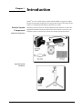
Chapter 1.
Introduction
SenSys® is an air-cooled camera system with the ability to acquire low-light
images by integrating (exposing) over long periods of time. The imager in the
camera is a scientific-grade charge-coupled device (CCD).
SenSys System
Components
All SenSys systems consist of standard hardware and software as well as the
appropriate interface hardware (discussed in the Installation Guide) for your
computer system. Some SenSys systems also include optional hardware.
Standard Components
Optional System
Hardware
1
About this
Manual
The SenSys User Manual is divided into five chapters. It is suggested that you
read the entire manual before operating the camera to ensure proper usage. The
chapters that follow this introduction are:
•
System Installation — Instructions for installing the camera system’s
hardware and software.
•
Component Descriptions — Functional description of each component
•
Troubleshooting — Answers to camera hardware problems
•
Specifications — Specifications for each camera system component
Note: To install a new camera, follow the instructions in the System Installation chapter
of this User Manual.
Environmental
Requirements
The SenSys camera system should be operated in a clean, dry environment. The
camera system requires that an easily accessible electrical outlet be available
near the equipment.
The camera system’s ambient operating temperature is 0°C to 40°C. The camera
can be operated in any orientation, therefore it can be used on a tripod camera
stand or mounted on a variety of instruments.
Storage
Requirements
Precautions
2
SenSys User Manual
Store the SenSys camera system in its original containers. To protect the system
from excessive heat, cold, and moisture, store at an ambient temperature
between -20°C and 60°C with a relative humidity of 0%–90% noncondensing.
The CCD and other system electronics are extremely sensitive to electrostatic
discharge (ESD). To avoid permanently damaging the system, please observe
the following precautions:
•
If you are using high-voltage equipment (such as an arc lamp) with your
camera system, be sure to turn the camera power on last and power the
camera off first.
•
Always switch off and unplug the power brick before changing your
system configuration in any way.
•
Use caution when triggering high-current switching devices (such as an
arc lamp) near your system. The CCD can be permanently damaged by
transient voltage spikes. If electrically noisy devices are present, an
isolated, conditioned power line or dedicated isolation transformer is
highly recommended.
•
Never connect or disconnect any cable while the camera system is
powered on. Reconnecting a charged cable may damage the CCD.
•
Never impede airflow through the equipment by obstructing the air
vents.
Repairs
Cleaning
Roper Scientific
Customer Service
Other than repairs described in this manual, all repairs must be done by Roper
Scientific. Should your system hardware need repair, contact Roper Scientific
Customer Service. Please save the original packing materials so you can safely
ship the camera system to another location or return it for repairs if necessary.
Clean exterior surfaces of the camera system with a dry, lint-free cloth. To
remove stains, contact Roper Scientific Customer Service.
If you have any questions about your camera system, contact Roper Scientific
Customer Service. When you call, please have your Roper Scientific job number
or equipment serial numbers available.
•
•
•
•
Tel:
Fax:
E-mail:
Mail:
800. 874.9789/ 520.889.9933 between 8:00 am and 5:00 pm MST
520.295.0299
[email protected]
Roper Scientific
3440 East Britannia Drive
Tucson, Arizona 85706
In Europe, you can reach Customer Service at:
BENELUX
•
•
•
•
Tel:
Fax:
E-mail:
Mail:
31.347.324989
31.347.324979
[email protected]
Roper Scientific, BV
Ir. D.S. Tuijnmanweg 10
4131 PN VIANEN, Netherlands
FRANCE
•
•
•
•
Tel:
Fax:
E-mail:
Mail:
33.160.86.03.65
33.160.86.07.09
[email protected]
Roper Scientific, SARL
Z.I. Petite Montagne Sud
4, rue de l'Oisans - C.E. 1702
91017 Evry Cedex, France
GERMANY
•
•
•
•
Tel:
Fax:
E-mail:
Mail:
49.89.660.779.3
49.89.660.779.50
[email protected]
Roper Scientific, GmbH
Rosenheimer Landstr. 87
D-85521 Ottobrunn, Germany
In Japan, you can reach Customer Service at:
•
•
•
•
Phone:
Fax:
E-mail:
Mail:
81.43.274.8022
81.43.274.8023
[email protected]
Nipon Roper, K.K.
D-10E 1-3 Nakase,
Mihama-ku, Chiba-shi
Japan 261-8501
General product information and answers to some customer service questions can
be found on our website: http://www.roperscientific.com
Chapter 1. Introduction
3
This page intentionally left blank.
4
SenSys User Manual
Chapter 2.
System Installation
Carefully review the Precautions section on page 2 before performing any of the
procedures outlined here. Again, use only a SenSys cable and a SenSys PCI card with
your SenSys camera. Using a different cable or PCI card may result in permanent
damage to your system.
Introduction
Your SenSys camera system has the following hardware components:
•
Camera Head
•
PCI Card
•
Data Cable
•
Power Brick
•
Power Cord
SenSys system components are linked by the data cable and controlled by your
host computer system via the application software. Power to the camera is
supplied by the power brick. All of these hardware and software components
should be included with your shipment. Refer to the information and figures in
System Components on page 1.
The CCD you selected is installed in your camera.
Keep all the original packing materials so you can safely ship the SenSys system
to another location or return it for service if necessary.
If you have any difficulty with any step of the instructions, call Roper Scientific
Customer Service.
Software
Compatibility
Requirements
Host Computer
Requirements
The SenSys package includes the RS Image™ capture software program
designed for use with your SenSys camera.
All other imaging software must also be PVCAM® -compatible. For full access to
imaging software functions, PVCAM must be version 2.5.2 or higher.
The host computer for your SenSys camera must have the following:
•
Windows® 95, Windows® 98, Windows® ME, Windows NT®,
Windows® XP, or Windows® 2000 operating system
•
200 MHz Pentium® II (or greater)
•
64 MB RAM (or greater)
•
CD-ROM drive
•
At least one unused PCI card slot
•
16-bit color display (or greater)
*To store images to a local hard disk, up to 8 MB of free disk space is needed per file.
5
If you are a Mac® user, the host computer for your SenSys camera must have the
following:
•
Macintosh® OS 8.X, 9.X, or OS X
•
64 MB RAM (or greater)
•
CD-ROM drive
•
At least one unused PCI card slot
•
Video adapter that supports 24-bit color (millions of colors)
*To store images to a local hard disk, up to 8 MB of free disk space is needed per file.
Multiple Cameras
PVCAM supports multiple open cameras. In order to use this function, your
imaging software must also support it. The RS Image capture software program
included with your system supports multiple cameras, as do many other imaging
packages.
If your imaging software supports multiple cameras, there must be a separate
PCI card for each camera. Multiple cameras can only be open simultaneously if
all use PCI interfaces.
Software
Installation
An Installation Guide appropriate to your system is included as an insert in the
CD-ROM case. This guide provides step-by-step instructions for installing the
camera interface software and the application software for Windows-based and
Macintosh-based PCs. Additional instructions are included for installing a PCI
card in your computer and capturing images.
The CD-ROM contains the following files.
6
SenSys User Manual
•
Readme text files — these files contain the latest information on the
software installations and should be read before you run the
PVCAMSetup program.
•
PVCAMSetup software program — this software installs the camera
interface software.
•
RSImageSetup software program — this software installs the RS Image
application program.
•
MacOS directory — this directory contains the files required for
installing on a Macintosh computer.
•
Acrobat directory — this directory contains subdirectories containing
installation programs for Acrobat® Reader®.
•
Manuals directory — this directory contains user manuals in PDF
format.
Connecting
Mount Adapters,
Tripod Mounts,
and Other
Instruments
C-Mount Adapter
The camera is shipped with a removable F- or C-mount adapter attached. If
applicable, change the mount adapter or attach a compatible lens. For
information on changing the mount adapter, installing a compatible lens, or
installing a standard tripod camera stand, see below.
The C-mount adapter is a standard threaded video mount with a standard Cmount flange focal distance and additional travel distance to allow parfocal
adjustment with a variety of instruments. For specifications, see C-Mount
Adapter on page 28.
When the C-mount adapter is in place, a lens with optics that protrude a long
distance into the camera may interfere with the shutter blades. To calculate
appropriate measurements, refer to page 28.
C-mount Assembly
To install the C-mount adapter (if not pre-installed):
1.
Using the .050” hex wrench provided, back out the setscrews so they do
not interfere with threading the mount in place. There is no need to
remove the setscrews.
2.
Thread the C-mount adapter onto the lens or instrument adapter. Lock
in place using the .050” hex wrench provided.
3.
Thread the C-mount adapter into the camera. (In certain cases, it may be
easier to thread the camera onto the C-mount adapter.)
To remove the C-mount adapter (if changing to a different adapter):
1.
Using the .050” hex wrench provided, back out the setscrews until you
can freely rotate the mount.
2.
Unscrew the mount from the camera.
Chapter 2. System Installation
7
F-Mount Adapter
The F-mount adapter is a standard Nikon bayonet mount with a standard Fmount flange focal distance and additional travel distance to allow parfocal
adjustment with a variety of instruments. For specifications, see F-Mount Adapter
on page 29.
F-mount Assembly
To install the F-mount adapter (if not pre-installed):
1.
Using the 1/16” hex wrench provided, back out the setscrews so they do
not interfere with threading the mount in place. There is no need to
remove the setscrews.
2.
Thread the F-mount adapter onto the camera.
3.
Insert the lens into the adapter and rotate it counterclockwise to lock. If
you don’t use a lens, simply attach your instrument’s F-mount adapter
to the camera or attach the camera to the instrument’s F-mount. (If your
instrument requires an F-mount adapter, contact your instrument
supplier.)
To remove the F-mount adapter (if changing to a different adapter):
8
SenSys User Manual
1.
Using the 1/16” hex wrench provided, back out the setscrews until you
can freely rotate the mount.
2.
Unscrew the mount from the camera.
Tripod Camera Stand
The SenSys camera has four mounting holes that are tapped for a standard
tripod mounting bolt.
Camera with Tripod Camera Stand
To mount the SenSys camera on a tripod camera stand:
1.
Loosen the tripod mount locknut so that the maximum length of the
tripod mounting bolt is exposed.
2.
Align the camera on the tripod mounting bolt, using one of the four
mounting holes on the camera body.
3.
Thread the tripod mounting bolt into the camera body.
4.
Tighten the locknut on the mount to secure the camera.
To remove the SenSys camera from a tripod mount:
1.
Loosen the tripod mount locknut.
2.
Unthread the tripod mounting bolt from the camera.
Other Instruments
If applicable, mount the camera on a compatible instrument or connect your
own trigger equipment to the 9-pin, female input/output (I/O) trigger port
located on the back of the camera. If you are using high-voltage equipment
(such as an arc lamp) with your camera system, be sure to turn the camera
power on last and power the camera off first. For trigger port pin-out
specifications, see page 31.
Installing the
PCI Card
You will be using a SenSys PCI card to allow the camera to communicate with
your computer.
Refer to the Readme text files on the CD-ROM and to the Installation Guide
supplied with the CD-ROM before installing the PCI card. Please follow the
instructions when installing the card.
After installing the PCI card, go to Connecting the Data Cable.
Chapter 2. System Installation
9
Connecting the
Data Cable
The Data cable connects your SenSys camera to the PCI card installed in your
computer.
Data Cable
To connect your SenSys camera:
1.
Connect either end of the Data cable to the Data port on the back of the
camera (see the figure below).
Camera Back
2.
10
SenSys User Manual
Connect the other end of the Data cable to the PCI card in the host
computer.
Connecting the
Power Brick
The power brick is a switched supply that is shipped with a power cord.
Caution: Connecting or removing a live power cable to or from the SenSys camera can
damage the camera's electronic components. Do not attach or remove any cables while
the power brick is switched on (On = |, Off = 0) and plugged into an electrical outlet.
To connect the power brick to the camera:
Power Brick Cable with 9-Pin, D Connector
1.
Connect the power brick cable's 9-pin, D connector to the power port on
the back of the camera. Secure by tightening the connector screws. Do
not extend this cable.
2.
With the power brick switched off and the power cord unplugged from
an electrical outlet, connect the power cord to the power brick (and later
to an electrical outlet).
Instructions for powering on and powering off the camera system are provided
in the Installation Guide supplied with the CD-ROM. When you turn on your
camera later (after installing the interface hardware), the red light on the camera
illuminates immediately, indicating that the camera has power. In 20-40
seconds, the green light illuminates, indicating that the camera has reached
operating temperature. See Status Lights on page 16 of this User Manual for more
information.
Chapter 2. System Installation
11
Focusing Your
Camera
After you have finished system installation and have started the application
software, you can focus the camera for the best image.
C-Mount Assembly
To focus the camera:
F-Mount Assembly
12
SenSys User Manual
1.
If needed, back out the setscrews until you can freely rotate the C-mount
adapter. Use the .050" hex wrench provided.
2.
Using the instructions from your software program, bring your software
into focus loop mode. For instructions on using RS Image to focus, see
the on-line help.
3.
Hold the camera so it does not rotate, then use the lens or instrument
adapter to adjust the C-mount adapter to the desired position.
4.
Tighten the setscrews until snug.
To focus the camera:
1.
If needed, back out the setscrews until you can freely rotate the F-mount
adapter. Use the 1/16" hex wrench provided.
2.
Using the instructions from your software program, bring your software
into focus loop mode. For instructions on using RS Image to focus, see
the on-line help.
3.
Hold the camera so it does not rotate, then rotate the F-mount adapter to
the desired position.
4.
Tighten the setscrews until snug.
Chapter 3.
Component Descriptions
The SenSys camera consists of the camera body and the shutter cover. The
camera body houses the CCD, CCD cooling system, and camera electronics. All
of the components inside the camera body are sensitive electronic components
and are not user accessible. Opening the camera body voids the camera warranty. The
shutter, located behind the shutter cover, is a user-replaceable component.
SenSys Camera with F-mount Adapter and Nikon Lens
CCD
MPP
Metachrome® II
Certificate of Performance
When you order a SenSys camera, you choose from a range of CCDs that differ
in size and grade. All SenSys CCDs are scientific-grade, grades with fewer
defects than commercial grades. Scientific-grade CCDs image with better
resolution, have low noise so they can detect weak signals, and are linear over
the dynamic range so you can accurately judge intensity differences between
objects.
All SenSys cameras have Multi-Pinned Phase (MPP) CCDs. MPP CCDs are built
to have less thermally generated noise for a given exposure time, a property
useful when trying to detect weak signals.
Metachrome II is a proprietary, optional, permanent CCD coating that is
available on all SenSys CCDs. This coating extends the CCD's sensitivity to
below 200 nm and is transparent from 400 to 1100 nm wavelength light. The
coating requires no maintenance and does not degrade over time.
Each SenSys camera has a Certificate of Performance. This certificate states the
CCD grade that has been designated by the CCD manufacturer. The certificate
also provides the camera performance information needed to effectively
measure photon flux with repeatable, scientific accuracy. A copy of the
information contained in the Performance Certificate is kept on file at Roper
Scientific Customer Service.
13
Window
The SenSys camera has one window in the optical path. The CCD does not have
a window. Compared to a multiple-window design, a single window reduces
the chance of image degradation due to multiple reflections, stray light, and
interference patterns.
The standard Photometrics window is made of fused silica (quartz) with a
broadband antireflective coating. Fused silica has better ultraviolet transmission
than crown glass. The antireflective coating increases the light transmitted
through the window from 92% to 99%, further decreasing light loss. Optional
infrared-blocking (IR) and sapphire windows are available. The IR window
blocks optical radiation above 650 nm, providing a sharper image. The sapphire
window may be necessary for high-humidity environments.
CCD Chamber
The window is part of the sealed chamber that protects the CCD from
contamination and excess ambient humidity. Inside the sealed chamber,
packages of desiccant absorb any water vapor.
When the camera is cooled to 10°C, the low-humidity environment prevents
frost from forming on the CCD and condensation from forming on the inside of
the window.
Thermoelectric
Cooler
Cooled CCD cameras produce less dark current than cameras operating at
ambient temperature. The CCD in the SenSys camera is cooled to 10°C when the
ambient temperature is between 10°C and 40°C.
The CCD is cooled by a single-stage Peltier cooler, a thermoelectric cooler (TEC)
that pulls heat away from the CCD. The heat is rejected into the camera body
and is passively radiated to the environment.
Shutter
The camera has a high-speed, customer-replaceable shutter that maintains a speed
of up to 15 frames per second while still fully opening and closing. The shutter
takes 5 ms to open and 10 ms to close. The camera integration time (the total time
any part of the CCD is exposed) is equal to the shutter open and close times plus
the exposure time.
The shutter is the only mechanical component that has a limited life with heavy
use. Instructions for testing and replacing the shutter are in Chapter 4.
Troubleshooting.
14
SenSys User Manual
Electronics
The CCD produces an analog signal. The camera electronics convert the analog
signal into a digital signal, data that can be received by the host computer.
Several factors influence what portion of the analog signal translates into digital
data. One factor is the noise in the camera system. The system noise includes the
thermal noise produced by the camera components and the read noise
determined in part by how far the analog signal must travel. The farther an
analog signal has to travel, the more the signal degrades.
To reduce signal degradation, SenSys has low-noise electronics and primary
point digitization (PPD™). The PPD design positions the analog-to-digital
converter (ADC) as close to the CCD as possible, which reduces the distance the
analog signal must travel.
Another determining factor is the quality of the signal received by the ADC. If
the ADC receives a high-quality signal, the 12-bit ADC digitizes the analog
signal into 12-bit data. With a lesser quality signal, the ADC produces data with
a lower effective bit depth.
The SenSys camera produces an analog signal that uses the full range of the 12-bit
ADC (up to 4096 gray levels). Through software, the camera can be set to High
Sensitivity (Gain 3), High Dynamic Range (Gain 2), or High Signal to Noise Ratio
(Gain 1) detection modes. Each gain setting configures the camera to be responsive
to different light-level intensity ranges. The appropriate range is dictated by the
specific use of the camera.
No matter how fast the data moves from the CCD to the ADC, the camera
readout rate is determined by how quickly the ADC converts the data to digital
form. The conversion rate of your SenSys camera is stated on the Certificate of
Performance.
Input/Output
Trigger Port
The SenSys camera has a TTL input/output (I/O) trigger port that is located on
the back of the camera. (See diagram on next page.) When the camera is
shipped, this port is fitted with a cover.
The I/O port allows you to synchronize the camera trigger signal with external
equipment. Strobes, external shutters, and filter motors are examples of external
triggering devices. The I/O port is a male, D-subminiature 9-pin connector.
Pinout specifications are located in Input/Output Port Pinout on page 31.
Data Port
Digital data is transmitted to the host computer through the PCI interface. The
Data port is a 68-pin, high-density, I/O connector with a standard AIA format.
The pinout for the parallel cable that mates to the Data port connector is located
in Data Cable Pinout on page 33.
Chapter 3. Component Descriptions
15
Power Port
The power port is a 9-pin, female, D connector. Pinout specifications for the port
are located in Power Port Pinout on page 32.
Camera Back
Status Lights
The back of the camera has two status lights:
Red light on
Power on
Green light on
CCD reached operating temperature
If the ambient temperature is between 0°C and 40°C, the CCD will usually reach
operating temperature within 20-40 seconds. If operating temperature is not
reached after approximately one minute, call Roper Scientific Customer Service.
16
SenSys User Manual
Power Brick
The power brick is a switched, multiple-output-voltage supply with a
detachable power cord. The camera system is powered on (|) and off (0) by a
switch on the supply. More detailed specifications are available in Chapter 5.
Specifications.
Caution: Connecting or removing a live power cable can damage the camera's electronic
components. Do not attach or remove any cables while the power brick is switched on
and plugged into an electrical outlet.
Power Brick with Integrated Cable and Power Cable
Lens Mount
Adapters
Each SenSys camera system is shipped with a removable C- or F-mount adapter.
The C-mount adapter allows the camera to be attached to many video camera
lenses and C-mount compatible instruments. The F-mount adapter allows the
camera to be attached to lenses and scientific instruments that are compatible
with a Nikon bayonet mount.
SenSys Mount Adapter and Lens Option
Chapter 3. Component Descriptions
17
The SenSys F- and C-mount adapters thread into the camera at a pitch of 32
threads/inch. When the camera is focused, two #6-32 inch socket setscrews (two
#4-40 inch socket setscrews for the C-mount) secure the adapters in place and
hold the optical alignment in parfocality. The setscrews are adjusted with a
long-handled 1/16” (or .050”) hex driver that is provided with the system.
Both mounts are shipped with a cap covering the aperture. The C-mount
adapter is a standard threaded video mount with a standard C-mount flange
focal distance and additional travel distance to allow parfocal adjustment with a
variety of instruments. The F-mount adapter is a standard Nikon bayonet mount
with a standard F-mount flange focal distance and additional travel distance to
allow parfocal adjustment with a variety of instruments. For mounted and
unmounted specification drawings, see Chapter 5. Specifications.
For C- and F-mount adapter installation, removal, and focusing instructions, see
Chapter 2. System Installation.
Lenses
Tripod Camera
Stand
18
SenSys User Manual
Roper Scientific sells lenses that are compatible with the SenSys lens mount
adapters. The F-mount lens is compatible with a standard Nikon bayonet
mount. The C-mount lens is a standard threaded video mount lens.
The camera has four tripod camera stand mounting holes (0.25”-20 UNC-2B
with a 1/4” depth). A tripod camera stand is available through Roper Scientific.
Chapter 4.
Troubleshooting
If you have any difficulty while troubleshooting, or do not see your camera system’s
symptoms listed here, contact Roper Scientific Customer Service.
The following issues have corresponding troubleshooting sections in this
chapter.
System Does Not Boot Normally
page 19
New Hardware Found Dialog Box Does Not
Appear (Windows 95/98/2000/ME)
page 20
Camera LED Does Not Illuminate
page 20
Spots in Image
page 20
Image is Smeared or Camera Will Not Reach
Saturation
page 20
Images Not Displayed Properly
page 20
Camera does not respond to light
page 21
Camera does not focus
page 23
PVCAM Error Message Appears
page 23
Lengthy Pauses During Imaging
page 23
Caution: Do not attach or remove any cables while the camera system is powered on.
System Does Not
Boot Normally
If your operating system does not boot normally after you have installed a PCI
card, try installing the new card in another open PCI slot. If this does not work:
1.
Turn off your computer and remove the newly installed PCI card.
2.
Turn your computer back on. If your system boots normally, there is
probably an interrupt conflict between a previously installed expansion card
and the PCI card that you are installing.
3.
If you need assistance resolving the interrupt conflict, contact Roper
Scientific Customer Service.
19
New Hardware
Found Dialog Box
Does Not Appear
(Windows
95/98/2000/ME/XP)
Green LED Does
Not Illuminate
If the New Hardware Found dialog box does not appear after installing a new
PCI card to your computer and booting Windows 95/98/2000/ME/XP:
•
Check to make sure that the new PCI card is inserted in a PCI slot according
to your computer manufacturer’s instructions and that the SenSys system’s
CD-ROM is in the host computer’s CD drive.
•
It is possible that there is a conflict between the new PCI card and a
previously installed expansion card. With the computer’s power turned off,
remove any previously installed expansion cards that your system does
not need to function. (If you are unsure which cards can be safely
removed, call Roper Scientific Customer Service.) Then turn your
computer back on and boot Windows 95/98/2000/ME/XP again.
•
If the New Hardware Found dialog box still does not appear, contact
Roper Scientific Customer Service.
Allow approximately one minute for the camera to reach operating temperature
and the green LED to come on. If the green LED does not illuminate, there may
be a problem with the camera's cooling system. Contact Roper Scientific
Customer Service.
Spots in Image
If you have spots in the image and the green LED is off but the camera is hot to
the touch, the CCD's temperature may be too cold and condensation may have
formed on the CCD or window. Turn off the camera IMMEDIATELY and
contact Roper Scientific Customer Service.
Image is Smeared
or Camera Will
Not Reach
Saturation
If the image is smeared (especially in high-intensity areas of the image) or the
camera will not reach saturation (4095 ADU) and the camera is set to gain state
1, make sure you use binning factors of at least 2 x 2. Because of the camera's
design, it only saturates at gain state 1 if binning factors of at least 2 x 2 are
defined.
Alternatively, if the light level is low enough, or you are unable to define
binning factors greater than 1 x 1, you could use gain state 2 or gain state 3.
Images Not
Displayed
Properly
If no images appear:
•
Confirm that the red LED on the back of the camera is illuminated,
indicating that the camera is powered on.
•
Confirm that the correct SenSys camera is selected in your imaging
software application.
•
Power off the camera and the host computer and check all system
connections (particularly both ends of the SenSys data cable). Restart. If
no images appear:
•
Confirm that Windows is set for at least 16-bit colors.
•
Confirm that the camera is operational by taking an image with a
standard C-mount lens attached to your SenSys.
•
Using normal room lighting, place the camera on a table about 3
meters away from an object and acquire an image using your
system’s Brightfield settings.
If the problem persists, contact Roper Scientific Customer Service.
20
SenSys User Manual
Camera Does Not
Respond to Light
If your camera has no response to light, a faulty camera shutter may be causing
the problem. To test for a malfunctioning shutter:
1.
Turn on the power to the camera.
2.
As the camera is powering up:
•
•
•
•
Camera Shutter Needs
Replacing
If you hear 2 clicks separated by 1 second (shutter opening then
closing), the shutter is working. Call Roper Scientific Customer
Service for further instructions.
If you do not hear any clicks, hear 1 click, or more than 2 clicks,
check the voltage between I/O port pins 3 and 9 while you are
powering up the camera. (See Input/Output Port Pinout on page 31.)
If the TTL logic level goes from 0 (low) to 1 (high), stays high for 1
second then drops to 0, the shutter signal is working, but the shutter
is not working. If this happens, you need to replace the shutter.
Follow the procedures in Camera Shutter Needs Replacing on page 21.
If the TTL logic levels do not indicate a working shutter signal, call
Roper Scientific Customer Service.
If your camera's shutter signal is working but the shutter needs to be replaced:
1.
Using a 3/32” hex wrench, remove the four #4-40 socket head screws
from the shutter cover.
Caution: Make sure to remove the shutter cover and not the camera back. Removing the
camera back will expose the CCD and void your warranty.
Chapter 4. Troubleshooting
21
22
SenSys User Manual
2.
Using a #1 Phillips screwdriver, remove the two #4-40 pan head Phillips
screws that attach the shutter board.
3.
Pull the shutter board straight up until it is unplugged from the main
board. Then unplug the shutter power connector from the shutter board.
4.
Using a standard screwdriver, remove the four #2-56 slotted binding
head screws that secure the shutter to the camera. Lift the shutter from
the camera.
5.
To install a new shutter, reverse the procedure.
Camera Does Not
Focus
If your SenSys camera is not focusing, find your camera configuration in the
following list:
•
An F-mount adapter is installed on your camera, and you are using an
F-mount lens.
See the focusing instructions in your imaging software and lens
documentation.
•
An F-mount adapter is installed on your camera, and the mount is
attached directly to an instrument.
See the instructions for focusing the camera in Focusing Your Camera on
page 12.
•
A C-mount adapter is installed on your camera, and you are using a
C-mount lens.
See the focusing instructions in your imaging software and lens
documentation.
•
A C-mount adapter is installed on your camera, and the mount is
attached directly to an instrument.
See the instructions for focusing the camera in Focusing Your Camera on
page 12.
PVCAM Error
Message Appears
Lengthy Pauses
During Imaging
If a PVCAM error message appears, note the message’s number code and
contact Roper Scientific Customer Service.
If you notice lengthy pauses marked by a lot of disk activity while imaging:
•
Close any other programs that may be running.
•
Install more physical memory to your computer system.
Chapter 4. Troubleshooting
23
This page intentionally left blank
24
SenSys User Manual
Chapter 5.
Camera
Specifications
Weight: 3 lbs without lens or lens mount
Width: 4.48 in (113.7 mm)
Length: 7.15 in (181.6 mm)
Thickness: 3.00 in (76.2 mm) for F-mount; 2.60 in (66.0 mm) for C-mount
Window thickness: 1 mm
Distance from top of shutter cover to CCD image plane:
CCD
F-mount Distance
C-mount Distance
0401E, 1602E, 3200E, and 3200ME
1.05 in (26.7 mm)
.63 in (16.0 mm)
1401E
1.07 in (27.2 mm)
.65 in (16.6 mm)
Distance from top of window to CCD image plane:
CCD
F-mount Distance
C-mount Distance
0401E, 1602E, 3200E, and 3200ME
.24 in (6.1 mm)
.24 in (6.1 mm)
1401E
.26 in (6.6 mm)
.26 in (6.6 mm)
Maximum ambient operating temperature: 40°C (104°F)
Minimum ambient operating temperature: 0°C (32°F)
Power dissipation: 15 watts
7.15 in
(181.6 mm)
4.48 in
(113.8 mm)
Camera Front View
25
C-Mount Camera
2.60 in
(66.0 mm)
7.15 in
(181.6 mm)
C-mount Camera Side View
2.60 in
(66.0 mm)
4.48 in
(113.8 mm)
C-mount Camera Top View
26
SenSys User Manual
F-Mount Camera
3.00 in
(76.2 mm)
7.15 in
(181.6 mm)
F-mount Camera Side View
3.00 in
(76.2 mm)
4.48 in
(113.8 mm)
F-mount Camera Top View
Chapter 5. Specifications
27
C-Mount Adapter
1.60 in dia.
(40.6 mm)
1.00-32 UN Thread
Top View of C-mount
1.60 in dia.
(40.6 mm)
Threads at
32 threads/inch
.26 in
(6.6 mm)
.96 in dia.
(24.5 mm)
1.50 in dia.
(38.1 mm)
Side View of C-mount (unmounted)
.32 in
(8.0 mm)
Shutter Blades
.63 in (16.0 mm) minimum
.71 in (18.0 mm) maximum*
CCD Focal Plane
Side View of C-mount (mounted) for KAF 0401E, KAF 1602E, KAF 3200E, and
KAF 3200ME
.32 in
(8.0 mm)
Shutter Blades
.65 in (16.6 mm) minimum
.73 in (18.5 mm) maximum*
CCD Focal Plane
Side View of C-mount (mounted) for KAF 1401E
* C-mount nominal back focal distance is 0.69 in (17.526 mm).
28
SenSys User Manual
F-Mount Adapter
1.93 in dia. 2.50 in dia.
(49.0 mm) (63.5 mm)
Top View of F-mount
.67 in
(17.0 mm) 1.02 in
(25.9 mm)
2.35 in dia.
(59.7 mm)
2.50 in dia.
(63.5 mm)
Side View of F-mount (unmounted)
1.72 in (43.7 mm) minimum
1.82 in (46.2 mm) maximum*
Threads at
32 threads/inch
1.05 in
(26.7 mm)
CCD Focal Plane
Side View of F-mount (mounted) for KAF 0401E, KAF 1602E, KAF 3200E, and
KAF 3200ME
1.74 in (44.2 mm) minimum
1.84 in (46.7 mm) maximum*
Threads at
32 threads/inch
1.07 in
(27.2 mm)
CCD Focal Plane
Side View of F-mount (mounted) for KAF 1401E
* F-mount nominal back focal distance is 1.83 in (46.5 mm).
Chapter 5. Specifications
29
Power Brick
2.25 in
(57.1 mm)
6.97 in
(177.0 mm)
3.74 in
(95.0 mm)
The power brick is a +5V DC and ±15V DC supply with 100-240V AC input at
50-60 Hz. The maximum power output is 55 W.
DC Voltage
Maximum Current Draw
+5
1A
+15
2.05 A during cooldown
700 mA after camera has reached regulated
temperature and during operation
-15
30
SenSys User Manual
80 mA
Input/Output Port
Pinout
The input/output port provides information about trigger function and shutter
status. All inputs are pulled up to +5V DC through 10k ohm resistors and filtered
with 2200pf ceramic capacitors. Outputs are driven by a 74F374 latch. The minimum
trigger pulse width is 1.1 µsec (1100 nsec).
The numbers on the trigger connector diagram below correspond with the
numbers given to the definition of each of the pins. The I/O connector is a
female, D-subminiature 9-pin connector.
Input/Output Port with Pin Numbers
1 SHUTTER OPEN OUTPUT
Active high. A high level on this output indicates that the shutter is completely
open. The output is low when the shutter is closed or in motion.
2 SHUTTER MOVING OUTPUT
Active high. A high level on this output indicates that the shutter is opening or
closing. The output is low when the shutter is completely open or completely
closed. The length of time this signal is held high is specified in PVCAM or by
the Shutter Open Delay and Shutter Close Delay functions in the software.
3 CAMERA EXPOSING OUTPUT
Active high. A high level on this output indicates that the camera is exposing
(integrating). This output does not include shutter open and close delay times.
4 FLASH
This pin is a TTL-level output that can be controlled through software by using
the FLASH command.
5 FACTORY SETUP
This pin is used for factory setup only and is not to be utilized by the user.
Driving this pin will disable the camera and cause a PVCAM error.
6 FILTERED TRIGGER INPUT
This input uses a TTL voltage level to trigger the camera. The input is pulled
low to initiate a trigger (default). If nothing is connected to the input, it is pulled
high to prevent the system from getting false triggers. To change the state of this
input see TRIGGER INVERT INPUT (8). (The inputs are internally pulled up,
therefore it is recommended to drive them with an open collector driver.)
Chapter 5. Specifications
31
7 TRIGGER INHIBIT INPUT
This input inhibits all trigger signals. If the input is pulled low, trigger activity is
disabled. By default, the input is pulled high so the trigger circuitry is enabled.
(The inputs are internally pulled up, therefore it is recommended to drive them
with an open collector driver.)
8 TRIGGER INVERT INPUT
Active low. A low on this input inverts the state of FILTERED TRIGGER INPUT
(6), causing a high level to cause a trigger. (The inputs are internally pulled up,
therefore it is recommended to drive them with an open collector driver.)
9 GROUND
System digital ground. Any external circuitry intended to interface with the
trigger control signals must reference this ground connection.
Power Port Pinout
Power Port Pinout
Pin #
32
SenSys User Manual
Signal Name
1
+5V DC
2
+5V DC
3
Ground
4
Ground
5
Ground
6
+15V DC
7
Ground
8
-15V DC
9
Ground
Data Cable Pinout
Data Cable Pinout
Pin #
Signal Name
Pin #
Signal Name
Pin #
Signal Name
1
Ground
24
N/C
47
VD5-
2
Ground
25
FEN+
48
VD4-
3
Ground
26
LEN+
49
VD3-
4
Ground
27
N/C
50
VD2-
5
Ground
28
N/C
51
N/C
6
VD11+
29
PIX+
52
N/C
7
VD10+
30
N/C
53
VD1-
8
VD9+
31
N/C
54
VD0-
9
VD8+
32
N/C
55
N/C
10
VD7+
33
N/C
56
TX-
11
VD6+
34
Ground
57
RX-
12
Ground
35
Ground
58
N/C
13
VD5+
36
VCC
59
FEN-
14
VD4+
37
VCC
60
LEN-
15
VD3+
38
VCC
61
N/C
16
VD2+
39
VCC
62
N/C
17
N/C
40
VD11-
63
PIX-
18
N/C
41
VD10-
64
N/C
19
VD1+
42
VD9-
65
N/C
20
VD0+
43
VD8-
66
N/C
21
N/C
44
VD7-
67
N/C
22
TX+
45
VD6-
68
Ground
23
RX+
46
Ground
Chapter 5. Specifications
33
CCD Orientation
Parallel
Serial
0,0
Camera Front View — KAF 0401E, KAF 1602E, KAF 3200E, and KAF 3200ME
CCD Orientation
0,0
Parallel
Serial
Camera Front View — KAF 1401E CCD Orientation
34
SenSys User Manual
CCD Specifications
KAF0401E H x V: 768 x 512
Pixel Size: 9µm x 9µm
Gain
Setting
Relative
Gain
Typical
Noise
System Gain
Typical Maximum ADC
Signal
High Signal to
Noise
1
≈1/2x
26e-
≈40e-/ADU
160Ke- (binned full well*)
High Dynamic
Range
2
≈1x
19e-
≈20e-/ADU
80Ke- (single pixel full
well)
High Sensitivity
3
≈4x
13e-
≈5e-/ADU
20Ke- (high sensitivity)
Detection Mode
* Binning must be a minimum of 2 pixels in the parallel and serial direction to reach the maximum ADC signal.
70
60
Quantum Efficiency %
50
40
30
20
10
0
400
500
600
700
800
900
1000
Wavelength (nm)
Typical QE Curve (not installed in camera)
QE response in the 200-400 nm range can be enhanced with Photometrics’ proprietary Metachrome II coating.
Chapter 5. Specifications
35
CCD Specifications
(continued)
KAF1401E H x V: 1317 x 1035
Pixel Size: 6.8µm x 6.8µm
Gain
Setting
Relative
Gain
Typical
Noise
System Gain
Typical Maximum ADC
Signal
High Signal to
Noise
1
≈1/2x
20e-
≈20e-/ADU
80Ke- (binned full well*)
High Dynamic
Range
2
≈1x
17e-
≈10e-/ADU
40Ke- (single pixel full
well)
High Sensitivity
3
≈4x
12e-
≈2.5e-/ADU
10Ke- (high sensitivity)
Detection Mode
* Binning must be a minimum of 2 pixels in the parallel and serial direction to reach the maximum ADC signal.
70
60
Quantum Efficiency %
50
40
30
20
10
0
400
500
600
700
800
900
1000
Wavelength (nm)
Typical QE Curve (not installed in camera)
QE response in the 200-400 nm range can be enhanced with Photometrics' proprietary Metachrome II coating.
36
SenSys User Manual
CCD Specifications
(continued)
KAF1602E H x V: 1536 x 1024
Pixel Size: 9µm x 9µm
Gain
Setting
Relative
Gain
Typical
Noise
System Gain
Typical Maximum ADC
Signal
High Signal to
Noise
1
≈1/2x
26e-
≈40e-/ADU
160Ke- (binned full well*)
High Dynamic
Range
2
≈1x
19e-
≈20e-/ADU
80Ke- (single pixel full
well)
High Sensitivity
3
≈4x
11e-
≈5e-/ADU
20Ke- (high sensitivity)
Detection Mode
* Binning must be a minimum of 2 pixels in the parallel and serial direction to reach the maximum ADC signal.
70
60
Quantum Efficiency %
50
40
30
20
10
0
400
500
600
700
800
900
1000
Wavelength (nm)
Typical QE Curve (not installed in camera)
QE response in the 200-400 nm range can be enhanced with Photometrics' proprietary Metachrome II coating.
Chapter 5. Specifications
37
CCD Specifications
(continued)
KAF3200E H x V: 2184 x 1472
Pixel Size: 6.8µm x 6.8µm
Gain
Setting
Relative
Gain
Typical
Noise
System Gain
Typical Maximum ADC
Signal
High Signal to
Noise
1
≈1/2x
18e-
≈22e-/ADU
90Ke- (binned full well*)
High Dynamic
Range
2
≈1x
15e-
≈11e-/ADU
45Ke- (single pixel full
well)
High Sensitivity
3
≈4x
10e-
≈2.5e-/ADU
10Ke- (high sensitivity)
Detection Mode
* Binning must be a minimum of 2 pixels in the parallel and serial direction to reach the maximum ADC signal.
70
60
Quantum Efficiency %
50
40
30
20
10
0
400
500
600
700
800
900
1000
Wavelength (nm)
Typical QE Curve (not installed in camera)
QE response in the 200-400 nm range can be enhanced with Photometrics' proprietary Metachrome II coating.
38
SenSys User Manual
CCD Specifications
(continued)
KAF3200ME
H x V: 2184 x 1472
Pixel Size: 6.8µm x 6.8µm
Gain
Setting
Relative
Gain
Typical
Noise
System Gain
Typical Maximum ADC
Signal
High Signal to
Noise
1
≈1/2x
18e-
≈22e-/ADU
90Ke- (binned full well*)
High Dynamic
Range
2
≈1x
15e-
≈11e-/ADU
45Ke- (single pixel full
well)
High Sensitivity
3
≈4x
10e-
≈2.5e-/ADU
10Ke- (high sensitivity)
Detection Mode
* Binning must be a minimum of 2 pixels in the parallel and serial direction to reach the maximum ADC signal.
100
90
80
Quantum Efficiency %
70
60
50
40
30
20
10
0
200
300
400
500
600
700
Wavelength (nm)
800
900
1000
1100
Typical QE Curve (not installed in camera
Chapter 5. Specifications
39
This page intentionally left blank.
40
SenSys User Manual
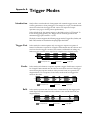
Appendix A
Introduction
Trigger Modes
SenSys offers several methods of integration with external trigger sources, such
as delay generators or laser pretriggers. The camera has a 9-pin, D-subminiature
connector on the back for trigger-in and various TTL input and output
operations (see page 31 for the pinout specifications).
In the default mode, the camera triggers on the falling edge of a TTL signal. To
invert the triggering polarity, the "Trigger Invert" must be grounded. The
minimum trigger pulse width is 1.1 µsec.
The SenSys camera supports the following trigger modes: Trigger-First, Strobe, and
Bulb. These modes are described in the paragraphs that follow.
Trigger-First
In this mode, the camera requires only one trigger to acquire a sequence of
frames. Each frame is exposed for a length of time entered into the software and
read out. Once the trigger is received, the camera is inhibited from taking any
further triggers until the entire sequence is completed (see diagram below).
Time in ms
0
50
100
150
Nonexposure Time
Strobe
250
300
350
Exposure Time
400
Trigger Signal
In this mode, each frame in a sequence requires a trigger. Each frame is exposed
for a length of time entered into the software and is then read out. If the trigger
arrives during the exposure-readout of the previous frame, it is ignored (see
diagram below). For a sequence of one frame, strobe mode and trigger-first
mode are the same.
Time in ms
0
50
100
150
Nonexposure Time
Bulb
200
200
250
300
Exposure Time
350
400
Trigger Signal
In this mode, exposure time for each frame is determined by the trigger pulse
width. Exposure time entered into the software is not used in this mode (see
diagram below).
Time in ms
0
50
100
Nonexposure Time
150
200
250
Exposure Time
300
350
400
450
Trigger Signal
41
This page intentionally left blank.
42
SenSys User Manual
Index
A-C
Analog signal, 15
Bulb mode, 41
Camera
cleaning, 3
repairs, 3
CCD. See Charge-Coupled Device (CCD)
CCD chamber, description, 14
CD-ROM files, 6
Certificate of Performance, 13
Charge-Coupled Device (CCD)
chamber, 14
description, 13
orientation, 34
specifications
KAF 0401E, 35
KAF 1401E, 36
KAF 1602E, 37
KAF 3200E, 38
KAF 3200ME, 39
use of thermoelectric cooler, 14
Cleaning, camera, 3
C-mount adapter
description, 18
focusing, 12
installing, 7
removing, 7
specifications, 26
Customer Service
in Europe, 3
in US, 3
worldwide, 3
D-H
Data cable pinout, 33
Data port, 15
Declaration of Conformity, iv
Environmental requirements, 2
F-mount adapter, 8
description, 18
focusing, 12
installing, 8
removing, 8
specifications, 27
Gain, available settings, 15
Hardware specifications
camera, general, 25
CCD orientation, 34
CCDs, 35–39
Hardware specifications (cont.)
C-mount adapter, 28
C-mount camera, 26
Data cable pinout, 33
F-mount adapter, 29
F-mount camera, 27
Input/Output (I/O) port pinout, 31
power brick, 30
Power port pinout, 32
Host computer requirements, 5
I-M
Input/Output (I/O) trigger port, 15
Input/Output port pinout, 31
Installation
software, 6
system, 5
Installation Guide, 6
KAF 0401E, specifications, 35
KAF 1401E, specifications, 36
KAF 1602E, specifications, 37
KAF 3200E, specifications, 38
KAF 3200ME, specifications, 39
Lens mount adapters, 17
Lenses, 18
Low-noise electronics, 15
Metachrome II, 13
Multi-Pinned Phase (MPP)
description, 13
Multiple cameras, 6
N-Q
Noise, 15
Performance certificate, 13
Ports
Data, 15
Input/Output (I/O), 15
Power, 16
Power brick
connecting, 11
description, 17
specifications, 30
Power port, 16
Power port pinout, 32
PPD. See Primary Point Digitization (PPD)
Precautions for SenSys camera, 2
Primary Point Digitization (PPD), 15
Chapter 5. Specifications
43
R-S
Readout rate, 15
Repairs, 3
Shutter
description, 14
location, 13
possible lens interference, 7
replacing, 21
Software compatibility requirements, 5
Software installation, 6
Specifications. See Hardware specifications
Status lights on camera, 16
Storage requirements, 2
Strobe mode, 41
System components, 1
System installation, 5–12
System noise, 15
T-Z
Thermoelectric cooler, description, 14
Trigger modes
Bulb, 41
44
SenSys User Manual
Trigger modes (cont.)
Strobe, 41
Trigger-First, 41
Trigger signal, synchronizing, 15
Trigger-First mode, 41
Tripod camera stand, 9, 18
Troubleshooting, 19
TTL I/O trigger port. See Input/Output (I/O)
trigger port
Warranties
image intensifier detector, ii
normal wear item disclaimer, i
one year, i
one year on refurbished/discontinued products, i
owner's manual and troubleshooting, ii
sealed chamber, i
software, ii
vacuum integrity, i
VersArray (XP) vacuum chamber, i
x-ray detector, ii
your responsibility, ii
Website, 3
Window, in SenSys camera, 14
BENELUX
Roper Scientific, BV
Ir. D.S. Tuijnmanweg 10
4131 PN VIANEN, Netherlands
tel: 31.347.324989
fax: 31.347.324979
email: [email protected]
FRANCE
Roper Scientific, SARL
Z.I. Petite Montagne Sud
4, rue de l'Oisans - C.E. 1702
91017 Evry Cedex, France
tel: 33.160.86.03.65
fax: 33.160.86.07.09
email: [email protected]
USA
Roper Scientific – Arizona
3440 East Britannia Drive
Tucson, Arizona 85706
tel: 800.874.9789 or 520.889.9933
fax: 520.295.0299
email: [email protected]
GERMANY
Roper Scientific, GmbH
Rosenheimer Landstr. 87
D-85521 Ottobrunn, Germany
tel: 49.89.660.779.3
fax: 49.89.660.779.50
email: [email protected]
JAPAN
Nipon Roper, K.K.
D-10E 1-3 Nakase,
Mihama-ku, Chiba-shi
Japan 261-8501
tel: 81.43.274.8022
fax: 81.43.274.8023
email: [email protected]
USA
Roper Scientific – New Jersey
3660 Quakerbridge Road
Trenton, New Jersey 08619
tel: 800.874.9789 or 609.587.9797
fax: 609.587.1970
email: [email protected]
57-054-001 Rev B3