1
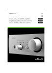
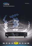
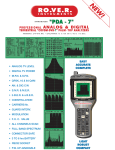
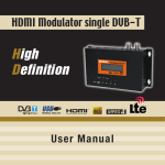
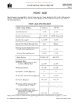
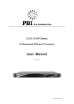
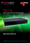
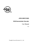
UC-250L2 BISS DVB-S2 Modulator User’s Manual Version: 2.0 Date :2014.04.26 NMS Version: V4.11 E SW: V6.11 HW: V4.5 DISITRON INDUSTRIES INC. DIRECTORY CHAPTER 1 PRODUCT OUTLINE ................................................................................. 1 1.1 OUTLINE ............................................................................................................. 1 1.2 FEATURES ......................................................................................................... 1 1.3 SPECIFICATIONS............................................................................................... 2 1.4 PRINCIPLE CHART ............................................................................................ 3 1.5 APPEARANCE AND DESCRIPTION ................................................................. 4 CHAPTER 2 INSTALLATION GUIDE ............................................................................. 6 2.1 ACQUISITION CHECK ....................................................................................... 6 2.2 INSTALLATION PREPARATION ....................................................................... 6 2.3 WIRE’S CONNECTION ........................... ERROR! BOOKMARK NOT DEFINED. 2.4 SIGNAL CABLE CONNECTION............. ERROR! BOOKMARK NOT DEFINED. CHAPTER 3 OPERATION ............................................................................................ 10 3.1 MAIN INTERFACE ............................................................................................ 11 3.2 GENERAL SETTING......................................................................................... 11 CHAPTER 4 NMS SETTING ......................................................................................... 24 4.1 INSTALLATION ................................................................................................ 24 4.2 SOFTWARE OPERATION ................................................................................ 24 4.3 UC-250L2 BISS DVB-S2 MODULATOR OPERATION .................................... 31 CHAPTER 5 TROUBLESHOOTING ............................................................................. 36 CHAPTER 6 PACKING LIST ........................................................................................ 37 UC-250L2 BISS DVB-S2 Modulator User’s Manual 1 Chapter 1 product outline 1.1 Outline The Upcom UC-250L2 BISS DVB-S2 Modulator is a professional grade modulation device developed according to EN302307 DVB-S2 second generation European broadcast standard. It adopts advanced framing structure, channel coding and modulation methods which increases the device’s transmission ability by more than 50% over previous generation DVB-S modulators under the same broadcast conditions. It will also provide better reception ability in the same spectral efficiency. The device is backwards compatible with DVB-S EN300421 modulation standards. The device can be controlled locally through front panel a LCD screen and navigation buttons or remotely through a NMS client. 1.2 Features Fully complies with DVB-S2 (EN302307) modulation standard. Backwards-compatible with DVB-S (EN300421) modulation standard. Two ASI inputs supporting automatic switchover in case of signal loss. Supports BISS scrambling modes: 0, 1 & E. Supports local and remote control. Output level attenuation control. 10MHz outer reference clock input. Output frequency range: 950~2150MHz. Full-size front panel LCD display and navigation buttons. 1 / 37 UC-250L2 BISS DVB-S2 Modulator User’s Manual 2 1.3 Specifications Supports both packet and byte mode TS inputs MPEG-TS Input Supports 188/204Byte transmission stream packets Two ASI inputs, supporting auto switchover ASI input connector: BNC, impedance 75Ω Frequency is adjustable from 950 to 2150MHz Output Level attenuation is adjustable from 0 to 31.5 dB; in steps of 0.5 dB. RF Output Maximum Output level: 0dBm MER≥32dB Connector: N type, impedance 50Ω DVB-S DVB-S2 RS coding BCH coding Inner coding Convolutional LDPC coding Code Rate 1/2,2/3,3/4,5/6,7/8 1/2,3/5,2/3,3/4,4/5,5/6,8/9, 9/10 Constellation QPSK QPSK,8PSK Roll-off Factor 0.2, 0.25, 0.35 0.2, 0.25, 0.35 Symbol Rate 0.1~45MBaud Outer coding Channel Coding and Modulation BISS Scramble Miscellaneous ---- 0.1~30M@8PSK; 0.1~45 M@QPSK Mode0, Mode1, Mode E Dimension 44mm×482mm×410mm Environmental 0~45 Power 100-240VAC±10%,50Hz-60Hz (operation), -20~80 (storage) 2 / 37 UC-250L2 BISS DVB-S2 Modulator User’s Manual 3 1.4 Principle chart 10MHz RF 10MHz Modulating ASI interface ASI interface CPU control LCD KEY RJ45 3 / 37 UC-250L2 BISS DVB-S2 Modulator User’s Manual 4 1.5 Appearance and description Front Panel Illustration 1. LCD display Power : Power Indicator Ext 10M : 10MHZ Outer Reference Clock ASI1 : ASI1 input ASI2 : ASI2 input 2. Indicators TS Overflow: Input TS bit rate over the Transmission bandwidth Alarm : Alarming Indicator DVB-S2: Current Modulation is DVB-S2 DVB-S: Current Modulation is DVB-S 8PSK: Current constellation is 8PSK QPSK: Current constellation is QPSK 3. Up/Down/Left /Right/Confirmation key 4. Menu key 5. Locking key 4 / 37 UC-250L2 BISS DVB-S2 Modulator User’s Manual 5 Rear Panel Illustration 1 2 3 4 5 6 7 1. Input of 10Mhz Outer Reference Clock 2. Output of 10Mhz Inner Reference Clock 3. ASI1Input 4. ASI2 Input 5. ASI1Loop Output 6. ASI2 Loop Output 7. Network Interface 8. RF Output 9. Power Socket 10. Grounding pole 8 9 10 5 / 37 UC-250L2 BISS DVB-S2 Modulator User’s Manual 6 Chapter 2 Installation Guide 2.1 Initial Check When first opening the device packaging, please check contents against the following list: UC-250L2 BISS DVB-S2 Modulator ASI Cable Power Cord If any item is missing please contact your point of purchase. 2.2 Installation Please follow all installation instructions included in this chapter. Users can refer to the rear panel chart during installation. The main content of this chapter include: Checking the device for shipping damage Preparing relevant environment for installation Installing UC-250L2 Modulator Connecting signal cables Connecting communication port (optional) 6 / 37 UC-250L2 BISS DVB-S2 Modulator User’s Manual 7 2.2.1 Device Installation Flow Chart Illustration: Acquis ition C heck F ixing D evice C onnecting G rouding Wire and P ower C ord C onnecting S ignal Wire S etting P arameter R unning D evice 2.2.2 Environmental Requirements Item Datacenter Requirement The distance between any 2 devices should be 1.2~1.5m. Walls should be no closer than 0.8m. Electric Isolation, Dust Free Datacenter Floor Volume resistivity of ground anti-static material: 1X10⁷~1X10¹⁰Ω, Grounding current limiting resistance: 1M (Floor bearing should be greater than 450Kg/㎡) Environment Temperature 5~40 (sustainable ),0~45 (short term), Relative Humidity 20%~80% sustainable Pressure 86~105KPa Door & Window Installing rubber strips for sealing door-gaps and dual pane glasses for windows is recommended. Fire Protection Fire alarm system and extinguishers are required. Power Ensure air conditioning, lighting and device power sources are on different circuits. Device requires AC power 100-240V 50-60Hz. Please carefully check before running. Installing air-conditioning is recommended. 10%~90% short time 7 / 37 UC-250L2 BISS DVB-S2 Modulator User’s Manual 8 2.2.3 Grounding Requirement Good grounding practices will ensure the proper function and long-term reliability of the device. This will provide protection from power surges and interference. It is imperative the unit is used only when properly grounded. Coaxial cable’s outer conductor and isolation layers should keep proper electric conduction with the device's metal housing. Grounding wires must contain copper conductors in order to reduce high frequency impedance. The grounding wire must also be as thick and as short as possible. Users should make sure the two terminations of their grounding cables are properly secured. Current pass-through should be tested. Anti-rust should be applied on all relevant connections. Do not include any other devices in this unit's grounding circuit. The minimum contact patch area between the grounding wire and the device’s frame should be no less than 25mm2. 2.2.4 Frame Grounding All the machine frames should be connected with protective copper strip. The grounding wire should be as short as possible and avoid circling. The minimum contact patch area between the grounding wire and the device’s frame should be no less than 25mm^2. 2.2.5 Device Grounding Connect the device’s grounding point to the rack's grounding pole with copper wire. 8 / 37 UC-250L2 BISS DVB-S2 Modulator User’s Manual 9 2.3 Grounding Wire Connection The grounding wire conductive screw is located on the device’s rear panel adjacent to the AC Plug connector. Connecting Power Cord User should insert one end into power supply socket and the other end into device’s AC power source. Connecting Grounding Wire If possible, connect the device's grounding wire in an unshared circuit. If the grounding circuit is to be shared with other devices, the grounding resistance should be equal to or less than 1Ω. Caution: Before connecting power cord to UC-250L2 BISS DVB-S2 Modulator, user should set the power switch to “OFF”. 2.4 Signal Cable Connections The signal cable connections consist of input and output signal cables. Descriptions of the possible connection types follow below: 2.4.1 ASI input and loop output cable illustration: 9 / 37 UC-250L2 BISS DVB-S2 Modulator User’s Manual 10 2.4.2 RF output interface connection The N-type RF output interface can be found on the device’s rear panel labeled “RF OUT”. Connect this interface to the transmission equipment’s RF input using coaxial cables. The physical connector is illustrated below: Chapter 3 Operation The UC-250L2 Modulator’s front panel contains an LCD screen and navigation buttons. Users can adjust the device configuration using this local interface. Keyboard Function Description: MENU: Canceling presently entered value, resuming previous setting; Return to previous menu. ENTER: Activates the parameters that need modification, or confirming the change after modification. LEFT/RIGHT: Menu navigation. UP/DOWN: Menu navigation. LOCK: Lock the screen / cancel the lock state. After pressing lock key, the system will question the user whether to save present settings to memory. If not, the LCD will display the current configuration state. At the "Resume Factory Settings" submenu, users can press "ENTER" key to confirm a return to factory settings. This will erase all current settings. 10 / 37 UC-250L2 BISS DVB-S2 Modulator User’s Manual 11 3.1 Main Interface The front panel LCD first row will display Company Name, Device Type and real time input bit rate in the. The second will display output RF frequency, Symbol Rate and FEC ratio (Forward Error Correction). UP C O M UC ‐250L 2 B IS S T S =05.654Mbps R F =1000.00MH z S ymb R ate=27.500M C onv=3/4 UP C O M UC ‐250L 2 B IS S T S =05.654Mbps R F =1000.00MH z S ymb R ate=27.500M F E C =3/4 3.2 General setting Pressing the “LOCK” key will unlock the front panel and display the following menus: 1 Alarm S tatus 2 S ys tem S etting 3 O utput S etting 4 Network S etting 5 S aving C onfig 6 L oading C onfig 7 V ers ion 8 L anguage By pressing UP or DOWN key to the specified menu item, then pressing ENTER to enter the submenu as following pages: Users can navigate to the desired menus by using the UP, DOWN, LEFT, RIGHT and ENTER control buttons. 3.2.1 Alarm Status T emperature: 34 C entidegree Alarm C ount: 0 11 / 37 UC-250L2 BISS DVB-S2 Modulator User’s Manual 12 3.2.1.1 Temperature The figure displayed in the first row shows the real-time device housing temperature. 3.2.1.2 Alarm count The Alarm count in the second row indicates the number of alarms. Whenever an abnormal event happens, the number will increase. 3.2.1.3 Alarm descriptions Users can navigate to this submenu to check alarm details. The alarm types are described below: 1. Ref Clock Lose: The modulator cannot detect external 10MHZ reference clock input. 2. No input TS : There is no detected ASI signal input. 3. Input TS Overflow: Input TS bit rate over transmission bandwidth limit. 4. Internal error: Internal device error. 5. Temperature Alarm: When the modulator’s housing temperature exceeds normal range. T emperature: 34 C entidegree Alarm C ount: 4 1. R ef C lock L os e 2. No input T S 4. Internal E rror 5. T emperature Alarm 12 / 37 UC-250L2 BISS DVB-S2 Modulator User’s Manual 13 3.2.2 System setting Navigating to the System Setting Menu will display the following submenus: 2.1 Alarm S tatus 2.2 R E F C lock S el 2.3 Input S elect 2.4 S ymbol R ate 2.5 R oll O ff 2.6 C onv C ode R ate 2.7 C ons tellation 2.8 P ilot Ins ert 2.9 B is s S etting 3.2.2.1 Modulation Mode 2.1 Modulate Mode D V B _S 2.1 Modulate Mode 1/1 [ D V B _S ] D V B _S 2 This submenu will allow user to choose between DVB-S and DVB-S2 broadcasting. DVB-S: QPSK DVB-S Modulation. DVB-S2: 8PSK or QPSK BISS DVB-S2 Modulation. 3.2.2.2 Reference Clock Select 2.2 R E F C lock S el internal 2.2 R E F C lock S el 1/1 [ internal ] external auto Internal: The modulator uses internal 10MHz crystal oscillator as reference clock. External: The modulator uses external 10 MHz input as reference clock. 13 / 37 UC-250L2 BISS DVB-S2 Modulator User’s Manual 14 Auto: The device will prioritize any detected external reference clock. If none is present, system will default to internal clock. 3.2.2.3 Input select 2.3 Input S elect AS I 1 2.3 Input S elect 1/1 [ AS I 1 ] AS I 2 Auto(AS I 1) Auto(AS I 2) This submenu will allow users to select the input interface. ASI1: The input TS sourced from port ASI1. ASI2: The input TS sourced from port ASI2. Auto (ASI1): The modulator will preferably select the input TS from ASI1 if it exists; otherwise it will select the input TS from ASI 2. Auto (ASI2): The modulator will preferably select the input TS from ASI2 if it exists; otherwise it will select the input TS from ASI 1. 3.2.2.4 Symbol rate 2.4 S ymbol R ate 27.500M Range: 0.1-45M@QPSK Constellation 0.1-30M@8PSK Constellation 3.2.2.5 Roll-off factor 2.5 R oll O ff 0.35 2.5 R oll O ff 1/1 [ 0.35 ] 0.25 0.20 14 / 37 UC-250L2 BISS DVB-S2 Modulator User’s Manual 15 This submenu will allow users to select the transmission Roll Off Factor. There are 3 possible options: 0.35, 0.25 and 0.20. 3.2.2.6 FEC rate/Convolutional code rate 2.6 C onv C ode R ate 3/4 2.6 C onv C ode R ate 1/1 1/2 2/3 [ 3/4 ] 5/6 7/8 When set to DVB-S broadcasting, the convolutional code value can be set in this sub-menu. The possible options are: 1/2, 2/3, 3/4, 5/6, 7/8. 2.6 F E C R ate 1/2 2.6 F E C R ate 1/2 [ 1/2 ] 3/5 2/3 3/4 4/5 5/6 2.6 F E C R ate 1/2 [ 8/9 ] 9/10 When set to DVB-S2 QPSK broadcasting, the FEC (Forward Error Correction) ratio can be set in this sub-menu. The possible rates are: 1/4, 1/3, 2/5, 1/2, 3/5, 2/3, 3/4, 4/5, 5/6, 8/9, 9/10. 2.6 F E C R ate 3/5 2.6 F E C R ate 1/1 [ 3/5 ] 2/3 3/4 5/6 8/9 9/10 15 / 37 UC-250L2 BISS DVB-S2 Modulator User’s Manual 16 When set to DVB-S2 8PSK broadcasting, the FEC (Forward Error Correction) ratio can be set in this sub-menu. The possible rates are: 3/5, 2/3, 3/4, 5/6, 8/9, 9/10. 3.2.2.7 Constellation This menu item only shows when MODULATOR STATE is set to DVB-S2. 2.7 C ons tellation Q P S K 2.7 C ons tellation 1/1 [ Q P S K ] 8P S K Users can choose between QPSK or 8PSK constellations. 3.2.2.8 Pilot Insert This menu item only shows when MODULATOR STATE is set to DVB-S2 2.8 P ilot Ins ert O ff 2.8 P ilot Ins ert 1/1 [ O ff ] O n User can choose whether to insert the Pilot block. 3.2.2.9 BISS Setting BISS: Basic Interoperable Scrambling System There are three available BISS Scrambling modes: 0, 1 & E. Sub-menus will vary depending on mode selection. Mode 0 is equivalent to OFF, or unscrambled Free-to-Air programming. 9.1 B is s Mode Mode 0 16 / 37 UC-250L2 BISS DVB-S2 Modulator User’s Manual 17 9.1 B is s Mode Modes 1 and E will enable BISS scrambling. Mode 1 will require a session word. Mode E will require an encrypted session word. 3.2.2.9.1 Mode 1 The following sub-menus will be available under Mode 1 scrambling: 9.1 B is s Mode 9.2 Input P ort [00] 9.3 S W D ata 3.2.2.9.1.1 Biss Mode 9.1 B is s Mode Mode 1 This submenu will display the currently selected BISS mode. 3.2.2.9.1.2 Input Port After parsing, input programming will display in this sub-menu. Users can navigate to individual programs to enable BISS scrambling. 2.01 C C T V ‐1 2.02 C C T V ‐2 2.03 C C T V ‐7 2.04 C C T V ‐10 2.05 C C T V ‐11 2.06 C C T V ‐12 2.07 C C T V ‐MUS IC 0.01 C C T V ‐1 [NO ] Y es 17 / 37 UC-250L2 BISS DVB-S2 Modulator User’s Manual 18 3.2.2.9.1.3 SW Data 9.3 S W D ata 0X 000000000000 9.3 S W D ata 0X 000000000000 SW: Session Word, a fixed 12-character number. User can set a session word for scrambling control. Once the SW (Session Word) has been set, a 64-bit CW (Control Word) will be derived from the SW according to the DVB-CSA (common scrambling algorithm) specification. Note: Enter hexadecimal values. 3.2.2.9.2 Mode E When the modulator is set to Mode E, the display will show the following: 9.1 B is s Mode 9.2 Input P ort [00] 9.3 ID S elect 9.4 E S W D ata 3.2.2.9.2.1 Biss Mode 9.1 B is s Mode Mode E This sub-menu will show the currently selected BISS scrambling mode. Press “ENTER” to change mode. 3.2.2.9.2.2 Input Port After parsing, input programming will display in this sub-menu. Users can navigate to individual programs to enable BISS scrambling. 18 / 37 UC-250L2 BISS DVB-S2 Modulator User’s Manual 19 2.01 C C T V ‐1 2.02 C C T V ‐2 2.03 C C T V ‐7 2.04 C C T V ‐10 2.05 C C T V ‐11 2.06 C C T V ‐12 2.07 C C T V ‐MUS IC 0.01 C C T V ‐1 [NO ] Y es 3.2.2.9.2.3 ID Select This submenu will allow users to enter the encrypted session word. 9.3 ID S elect D evice 9.3 ID S elect [D evice] Input 9.5 Input D ata 0X 00000000000000 If “Device” is selected, enter a 14-character number to be set as one part of an encrypted session word. An ESW (encrypted session word) is also necessary. Refer to menu 3.2.2.8.2.4 for more details. If “Input” is selected, fixed data from the device will be used to encrypt programs. 3.2.2.9.2.4 ESW Data 9.4 E S W D ata 0X 0000000000000000 19 / 37 UC-250L2 BISS DVB-S2 Modulator User’s Manual 20 ESW: Encrypted Session Word, a 16-character number This submenu will not be visible if device is set to “Device” mode. Users can set an ESW value together with the ‘Input ID’ to complete encryption. Note: Once the ESW has been entered by the front panel or by the NMS client, it shall become impossible to read it back through any unit interface. The manual entry of the ESW shall also be in hexadecimal form; the 16 digits are entered with the most-significant digit first. 3.2.3 Output setting Navigating to Output Setting Menu will display the following submenus: 3.1 R F F requency 3.2 R F L evel AT T 3.3 S pec Invert 3.4 R F O utput 3.2.3.1 RF setting This submenu will allow users to set the RF output frequency. The RF output frequency ranges from 950 to 2150MHz. 3.1 R F F requency 1000.00MH z 3.2.3.2 RF ATT Setting This submenu will allow users to set the RF output attenuation. The RF attenuation ranges from 0-31.5db, adjusted in 0.5db steps. 3.2 R F L evel AT T 30.5 db 3.2.3.3 Spectrum Invert This submenu will allow users to invert the RF spectrum output. 20 / 37 UC-250L2 BISS DVB-S2 Modulator User’s Manual 21 3.3 S pec Invert normal 3.3 S pec Invert 1/1 [ normal ] invert 3.2.3.4 RF Output 3.4 R F O utput s ingle tone 3.4 R F O utput 1/1 [ s ingle tone ] modulation off This submenu will allow users to set the RF output mode for different applications. Single tone: The RF output is an un-modulated carrier. Modulation: A modulated output carrier. 21 / 37 UC-250L2 BISS DVB-S2 Modulator User’s Manual 22 Off: Turns off the RF output. 3.2.4 Network setting Navigating to the Network Setting menu will display the following submenus: ▶ 4.1 IP Addres s 4.2 S ubnet Mas k 4.3 G ateway 4.4 C ons ole Addres s ▶ 4.5 MAC Addres s Note: The unique MAC address is set at the factory. 22 / 37 UC-250L2 BISS DVB-S2 Modulator User’s Manual 23 4.1 IP Addres s 192.168.000.136 4.2 S ubnet Mas k 255.255.255.000 4.3 G ateway 192.168.000.001 4.4 C ons ole Addres s 192.168.000.221 4.5 MAC Addres s f f f f f f f f f f f f 3.2.5 Saving config User can choose to save the current configured parameters by pressing ENTER key. S aving, pleas e wait: eras ing... 3.2.6 Load config ▶ 6.1 L oad S aved C F G 6.2 L oad D efault C F G User can restore the device to the last saved configuration by choosing “6.1” or restore the device to factory configuration by choosing “6.2”. 3.2.7 Version User can check the hardware and software versions of the equipment in this submenu. UP C O M S W 6.01 H W 4.1 23 / 37 UC-250L2 BISS DVB-S2 Modulator User’s Manual 24 3.2.8 Language Settings This submenu will allow users to set the system language. 8 L anguage 中文 [ E nglis h ] Chapter 4 NMS Setting Network Management System Profile A Network Management System enables the remote control and monitoring of Digital TV equipment through a computer network. 4.1 Installation NMS software does not require installation. Extract NMS files to desired directory on local drives. Two files will be generated once NMS client has been executed. Network management software X.XXY.log (preserves the log file) Info. Bin (user configuration data) 4.2 Software Operation 4.2.1 Login Interface A login interface will pop up when the software is running and give user prompts to input user name and password: 24 / 37 25 UC-250L2 BISS DVB-S2 Modulator User’s Manual User can login the NMS by pressing Confirm key after inputting user name and password. Default username and password is: admin 4.2.2 Main Interface This software will allow the user to edit various parameters in the device tree for management and classification. 25 / 37 26 UC-250L2 BISS DVB-S2 Modulator User’s Manual 4.2.3 Adding Frequency Point To begin, add a Frequency Point. This can be done by clicking “Add Freq Point” within the ‘Edit’ drop down menu. 26 / 37 27 UC-250L2 BISS DVB-S2 Modulator User’s Manual Alternatively, users can right click on an empty section of the left hand side column to pop up a short-cut menu and selecting “Add Main Freq Point”. 27 / 37 28 UC-250L2 BISS DVB-S2 Modulator User’s Manual 4.2.4 Adding Equipment under Given Frequency Point When a Freq Point is selected, users can add equipment by right clicking then selecting ‘Add Equipment’ within the ‘Edit’ drop down menu. 28 / 37 UC-250L2 BISS DVB-S2 Modulator User’s Manual 29 4.2.5 Edit Equipment Interface Users should follow the steps as below: Enter the device IP Address Enter the device Port Number (Default: 2007) Enter the desired Equipment Name Choose the correct equipment type in the drop down list of “Equipment Type” by clicking the “▼” or click symbol “?” to automatically determine the equipment type. 4.2.6 Delete Equipment Users can remove equipment from device chains by right clicking the intended target and selecting “Delete” in the pop-up menu. 29 / 37 UC-250L2 BISS DVB-S2 Modulator User’s Manual 30 4.2.7 Save Configuration Once satisfied with configured settings users can commit the changes to memory by clicking the button on the toolbar. Previous settings can be reloaded from memory by clicking the button. Users can also save and load setting configurations to their computer’s hard drive. Clicking the button will pop-up a “Save File” dialog box which will allow users to choose their configuration file destination. Similarly, users can click the button to popup the “Read File” dialog box. User can then choose which configuration file to load unto the device. 30 / 37 31 UC-250L2 BISS DVB-S2 Modulator User’s Manual 4.3 UC‐250L2 BISS DVB‐S2 Modulator Operation Users can configure the UC-250L2 Modulator in this interface. Set: Applies configuration to device. Get: Reads current device configuration. 4.3.1 Modulation Mode User can select the modulator’s working mode and relevant constellation at this drop-down list. 31 / 37 32 UC-250L2 BISS DVB-S2 Modulator User’s Manual DVB-S: DVB-S Modulation (QPSK) DVB-S2 QPSK: DVB-S Modulation (QPSK) DVB-S2 8PSK: DVB-S Modulation (QPSK) 4.3.2 Reference Clock Internal: The modulator uses internal 10MHz crystal oscillator as reference clock. External: The modulator uses external 10 MHz input as reference clock. Auto: The device will prioritize any detected external reference clock. If none is present, system will default to internal clock. 4.3.3 Input Select ASI1: The input TS sourced from port ASI1. ASI2: The input TS sourced from port ASI2. Auto (ASI1): The modulator will preferably select the input TS from ASI1 if it exists; otherwise it will select the input TS from ASI 2. Auto (ASI2): The modulator will preferably select the input TS from ASI2 if it exists; otherwise it will select the input TS from ASI 1. 4.3.4 Roll off factor This submenu will allow users to select the transmission Roll Off Factor. There are 3 possible options: 0.35, 0.25 and 0.20. 4.2.5 Conv Rate When set to DVB-S broadcasting, the convolutional code value can be set in this sub-menu. The possible options are: 1/2, 2/3, 3/4, 5/6, 7/8. 4.2.6 FEC Code Rate When set to DVB-S2 QPSK broadcasting, the FEC (Forward Error Correction) ratio can be set in this sub-menu. The possible rates are: 1/4, 1/3, 2/5, 1/2, 3/5, 2/3, 3/4, 4/5, 5/6, 8/9, 9/10. 32 / 37 UC-250L2 BISS DVB-S2 Modulator User’s Manual 33 4.2.7 Pilot Insert User can choose whether to insert the Pilot block in the check box. 4.2.8 Symbol Rate Range: 0~45M@QPSK Constellation 0~30M@8PSK Constellation 4.2.9 RF ATT User can set the attenuation of the RF output. The RF attenuation range is from 0-31.5db in 0.5db steps. 4.2.10 Modulation On Optional: User can set the RF output mode for different applications. Single tone: the RF output is an un-modulated carrier. Modulation: The RF output is a modulated carrier. Off: Turn off the RF output. 4.2.11 RF User can set RF output frequency. The RF output frequency ranges from 950 to 2150MHz. 33 / 37 34 UC-250L2 BISS DVB-S2 Modulator User’s Manual 4.2.12 BISS 4.2.12.1 ESW Data (3.2.2.8.2.4) ESW: Encrypted Session Word, a 16-character number This submenu will not be visible if device is set to “Device” mode. Users can set an ESW value together with the ‘Input ID’ to complete encryption. Note: Once the ESW has been entered by the front panel or by the NMS client, it shall become impossible to read it back through any unit interface. The manual entry of the ESW shall also be in hexadecimal form; the 16 digits are entered with the most-significant digit first. 4.2.12.1 SW Data (3.2.2.8.1.3) SW: Session Word, a fixed 12-character number. User can set a session word for scrambling control. Once the SW (Session Word) has been set, a 64-bit CW (Control Word) will be derived 34 / 37 35 UC-250L2 BISS DVB-S2 Modulator User’s Manual from the SW according to the DVB-CSA (common scrambling algorithm) specification. Note: Enter hexadecimal values. 4.2.12.3 Input ID (3.2.2.8.2.3) In this interface, user can set the input ID. 4.2.12.4 Word Mode (3.2.2.8) There are three possible options provided to be selected: Mode0, Mode 1 and Mode E. User can refer to 3.2.2.8 for more details. 4.2.12.5 Select ID (3.2.2.8.2.3) There are two possible options provided to be selected: Input and Device. User can refer to 3.2.2.8.2.3 for more details. 4.2.13 BISS Program Select In this interface, user can decide the programs need to be scrambled by selecting the items in the left column, and then clicking the button to put them in the right column. User can also remove the selected programs to left column by clicking 35 / 37 UC-250L2 BISS DVB-S2 Modulator User’s Manual 36 button. It is necessary to set a timeout value for parsing program, here bigger values are recommended so that more programs have enough time to be parsed. After finished the selection, use can click “Parse In” to confirm. Chapter 5 Troubleshooting Our ISO9001 quality assurance program has been approved by the CQC. All Upcom products pass testing and inspection before shipment. Please follow all instructions in this manual for proper device operation. Immediately Unplug the device if: Power cord or socket damage occurs. Any liquid flowed into the device. Any dust causes a short circuit. Device is present in a damp environment. Device suffers from physical damage. Long term idle periods are planned. Maintenance is needed. Longtime idle. After switching on and restoring to factory setting, device still cannot work properly. Maintenance needed 36 / 37 37 UC-250L2 BISS DVB-S2 Modulator User’s Manual Chapter 6 Packing List UC-250L2 BISS DVB-S2 Modulator 1pcs Power cord 1pcs ASI Cable 1pcs 37 / 37