1
8.3
MIS34x & MIS43x Registers
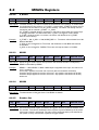
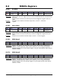
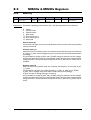
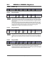
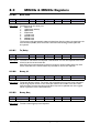
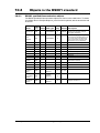
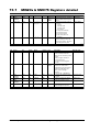
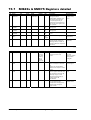
8.3.71
Input_Filter_Mask
Reg
Name
Size
Access
Range
Default
Unit
MacTalk name
135
INPUT_FILTER_
MASK
32bit
R/W
-
0
IO Mask
IOx digital input
filter enabled
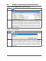
Description: This register controls filtering of each of the eight IO pins that are used as digital
inputs. If the bit corresponding to the input number is set in this register, the input value
will be filtered to a new logical level is only accepted after that level has been measured
on the hardware pin for the number of milliseconds specified in register 136. If the bit is
not set, the input will be updated directly from the hardware value every 100
microseconds. Please read the section on Digital Input filters in this manual.
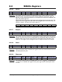
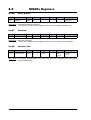
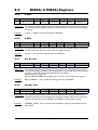
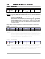
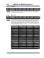
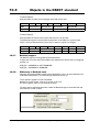
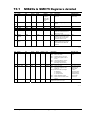
8.3.72
Input_Filter_Cnt
Reg
Name
Size
Access
Range
Default
Unit
MacTalk name
136
INPUT_FILTER_
CNT
32bit
R/W
-
5
ms
Input filter time
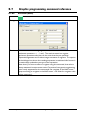
Description: The filtering of all of the eight digital inputs is controlled by the value in this register
together with register 135. The input must be sampled at the same value for the specified
number of milliseconds in this register to be accepted as the new filtered value. See also
the section on Digital Input Filters in this manual.
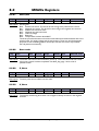
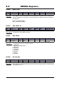
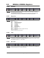
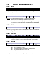
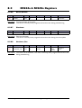
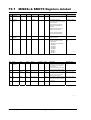
8.3.73
Inpos_Mask
Reg
Name
Size
Access
Range
Default
Unit
MacTalk name
137
INPOS_MASK
32bit
R/W
-
0
IO MASK
Dedicated Outputs
- In Position
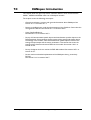
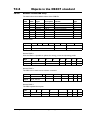
Description: Selects which one of the eight IO pins to use for the dedicated function of In Position
Output.
Exactly one bit must be set, and the IO pin must be configured in register 125 as an
output.
The In Position output will then be set after a movement has completed.
Example:
If output 1 is to be used for the In Position Output, write 20 = 1 to this register.
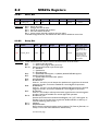
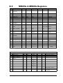
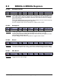
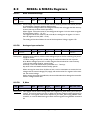
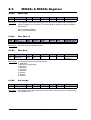
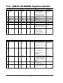
8.3.74
Error_Mask
Reg
Name
Size
Access
Range
Default
Unit
MacTalk name
138
ERROR_MASK
32bit
R/W
-
0
IO Mask
Dedicated Outputs
- Error
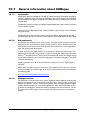
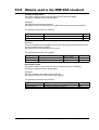
Description: Selects which one of the eight IO pins to use for the dedicated function of Error Output.
Exactly one bit must be set, and the IO pin must be configured in register 125 as an
output.
The Error Output will set be set when any error is set.
See register 35 (Err_Bits, page 123) for more information on errors.
Example:
If output 3 is to be used for the Error Output, write 22 = 4 to this register.
JVL Industri Elektronik A/S - User Manual - Integrated Stepper Motors MIS23x, 34x, 43x
171