1
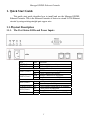
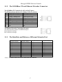
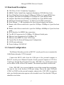
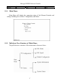
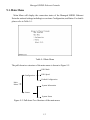
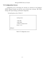
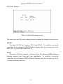
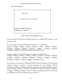
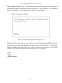
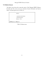
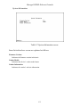
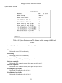
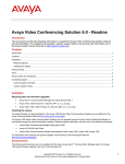
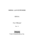
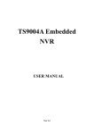
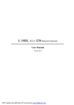
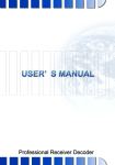
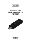
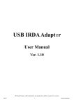
2-Pair
Managed SHDSL Ethernet Extender
User’s Manual
Managed SHDSL Ethernet Extender
1. Quick Start Guide
This quick start guide describes how to install and use the Managed SHDSL
Ethernet Extender. This is the Ethernet Extender of choice to extend 10/100 Ethernet
circuits by using existing straight pair copper wire.
1.1. Physical Description
1.1.1. The Port Status LEDs and Power Inputs
LEDs
POWER (Green)
TEST (Yellow)
Line
LOOP1 (Green)
LOOP2 (Green)
State
On
On
Indication
Power supply is normal.
Self testing after powered on.
Flash
On
Flash
On
SHDSL connection is in progress.
Loop1 connects successfully.
SHDSL connection is in progress.
Loop2 connects successfully.
On
Flash
On
On
Flash
On
LAN1 port is in connection.
Data activity on LAN1 port.
LAN1 Ethernet connection is at 100Mbps.
LAN2 port is in connection.
Data activity on LAN2 port.
LAN2 Ethernet connection is at 100Mbps.
Ethernet
LAN1 (Green)
10/100M (Green)
LAN2 (Green)
10/100M (Green)
1
Managed SHDSL Ethernet Extender
1.1.2. The 10/100Base-TX and Ethernet Extender Connectors
The 10/100Base-TX Connection (LAN1 and LAN2 ports)
The following lists the pinouts of 10/100Base-TX RJ-45 connector.
Pin
Regular Ports
Uplink ports
1
Output Transmit Data +
Input Receive Data +
2
Output Transmit Data Input Receive Data 3
Input Receive Data +
Output Transmit Data +
4
NC
NC
5
NC
NC
6
Input Receive Data Output Transmit Data 7
NC
NC
8
NC
NC
The Ethernet Extender Connection (Line port)
The RJ-48 interface pinouts for SHDSL line port.
Pin 4 & Pin 5 for Loop 1.
Pin 1 & Pin 2 for Loop 2.
1.1.3. The Data Rate and Distance of Ethernet Extender Port
1 pair
Data Rate (Kbps)
4,608
3,072
2,304
2,048
1,544
1,152
768
512
384
256
192
2 pair
Data Rate (Kbps)
9,216
6,144
4,608
4,096
3,088
2,304
1,536
1,024
768
512
384
Max. Reach (m)
Max. Reach (ft.)
1,828
2,895
3,505
3,657
3,962
4,419
4,572
5,029
5,334
5,791
6,248
6,000
9,500
11,500
12,000
13,000
14,500
15,000
16,500
17,500
19,000
20,500
<Note> This table is based on SHDSL connection with 1dB noise.
2
Managed SHDSL Ethernet Extender
1.2. Functional Description
z
z
z
z
z
z
z
z
z
z
z
z
z
z
z
z
ITU-T Rec. G.991.2 G.shdsl.bis Compliance.
SHDSL Trellis Coded Pulse Amplitude Modulation (TCPAM) Line Code.
Fixed Data Rate Selection from 10.8Mbps to 128Kbps for 2-pair SHDSL lines.
Adaptive Data Rate from 4608Kbps to 192Kbps for 1-pair SHDSL mode.
Adaptive Data Rate from 9216Kbps to 384Kbps for 2-pair SHDSL mode.
Maximum Transmission Distance: 22,500 ft over 26AWG twisted pair.
Noise Margin ≧ 1 dB is guaranteed for fixed rate and adaptive rate modes.
Remote side follows central side’s speed for 192Kbps~2304Kbps in 1-pair fixed rate
mode.
Remote side follows central side’s speed for 384Kbps~4608Kbps in 2-pair fixed rate
mode.
RJ-48 Interface for SHDSL line connections.
Two RJ-45 Connectors for 10/100Base-TX Ethernet Switch ports.
Ethernet Auto-Negotiation for 10/100Base-TX.
Ethernet Auto-MDIX for Auto Tx/Rx Swap.
Console Port for Network Management Configurations.
8 LED status indicators.
Power feedings: 100/240VAC.
1.3. Console Configuration
The Ethernet Extender provides an RS232C console port for user to monitor the
OA&M status through a VT100 terminal.
Connect the RS232 cable from the COM port of the personal computer to
RS232C console port of Ethernet Extender. Set the personal computer to VT100 or
VT102 type through HyperTerminal. Press the <ESCAPE> key and the main menu
will be shown on the screen of the terminal. The terminal operations can then start.
If the <ESCAPE> key is pressed and the screen of the terminal does not display,
this may be due to the incorrect COM port setting. Choose the right COM port
(COM1 or COM2) on the personal computer, and press the <ESCAPE> key again to
make sure that the main menu appears on the terminal screen. Note that the COM port
should be set as below.
3
Managed SHDSL Ethernet Extender
Baud rate
9600bps
Data bits
8
Parity
none
Stop bit
1
Flow control
none
1.3.1. Main Menu
Main Menu will display the connection status of the Ethernet Extender and
settings including two sections: Configuration, and Status.
1.3.2. Pull-down Tree Structure of Main Menu
The pull-down tree structure of the main menu is shown as below.
4
Managed SHDSL Ethernet Extender
1.4. Installation Procedures
z Connect both Ethernet Extenders to the AC outlet by power cords and turn on both
Ethernet Extenders by turning on the power switches of both Ethernet Extenders.
z Please refer Console Configuration section to configure both Ethernet Extenders.
Type 1 in Main Menu screen to select 1 Configuration. Type 1 in Configuration
screen to select 1 DSL Mode.
z Set CO/RT to STU-C in DSL Mode screen for one Ethernet Extender at Central Side
and set CO/RT to STU-R in DSL Mode screen for another Ethernet Extender at
Remote Side. It is necessary to set Ethernet Extender to STU-C and the other Ethernet
Extender to STU-R to establish a successful connection for two Ethernet Extenders.
z Set PAIR to 1 Pair or 2 Pairs in DSL Mode screen for both Ethernet Extenders at
Central Side and Remote Side. It is necessary to set the two Ethernet Extenders to the
same selection (1 Pair or 2 Pairs) to establish a successful connection for two Ethernet
Extenders.
z Type 1 in Main Menu screen to select 1 Configuration. Type 2 in Configuration
screen to select 2 DSL Speed. The user must set both Ethernet Extenders to the same
speed selection in order to establish a successful connection.
z Turn off both Ethernet Extenders by turning off the power switches of both Ethernet
Extenders.
z Connect CAT.5 UTP Ethernet straight cable with RJ-45 connectors or straight
telephone cable with RJ-45 connectors (2 pairs with Pin 4 & Pin 5 for Loop 1 and Pin
1 & Pin 2 for Loop 2) to Line ports (Ethernet Extender port with RJ-48 interface) of
both Ethernet Extenders.
z Turn on both Ethernet Extenders by turning on power switches of both Ethernet
Extenders. Both Ethernet Extenders will then execute self-test routines. Please wait
for LOOP1 LED (1 pair) or both LOOP1 and LOOP2 LEDs (2 pairs) of both Line
ports becoming stable on. The maximum fixed data rate is 5696Kbps and 10.8Mbps
for 1-pair and 2-pair mode. The maximum adaptive rate is 4608Kbps and 9216Kbps
for 1-pair and 2-pair mode. When setting for adaptive rate, 2 or more activation
cycles are necessary. Both Ethernet Extenders will automatically adapt to maximum
speed according to loop distances. Approximate 2~3 minutes for the LOOP1 LED (1
pair) or both LOOP1 and LOOP2 LEDs (2 pairs) of both Line ports become stable on.
z Note that this Ethernet Extender supports two Ethernet Switch ports (LAN1 and
LAN2 ports) with RJ-45 connectors. Connect Ethernet to either LAN1 or LAN2 port
of both Ethernet Extenders with CAT.5 UTP Ethernet straight cable with RJ-45
connectors.
5
Managed SHDSL Ethernet Extender
2. Table of Contents
1. QUICK START GUIDE ................................................................. 1
1.1.
PHYSICAL DESCRIPTION ............................................................................ 1
1.1.1.
The Port Status LEDs and Power Inputs.................................................................................................................... 1
1.1.2.
The 10/100Base-TX and Ethernet Extender Connectors............................................................................................ 2
1.1.3.
The Data Rate and Distance of Ethernet Extender Port ............................................................................................ 2
1.2.
1.3.
FUNCTIONAL DESCRIPTION ....................................................................... 3
CONSOLE CONFIGURATION ....................................................................... 3
1.3.1.
Main Menu ................................................................................................................................................................. 4
1.3.2.
Pull-down Tree Structure of Main Menu.................................................................................................................... 4
1.4.
INSTALLATION PROCEDURES .................................................................... 5
2. TABLE OF CONTENTS ................................................................ 6
3. INTRODUCTIONS......................................................................... 7
4. APPLICATION NOTES................................................................. 7
5. FEATURES...................................................................................... 8
6. PACKING CONTENTS ................................................................. 8
7. INSTALLATION PROCEDURES................................................ 9
8. FRONT PANEL LED INDICATORS......................................... 11
9. CONSOLE PORT CONTROL .................................................... 12
9.1.
9.2.
9.3.
MAIN MENU ............................................................................................ 13
CONFIGURATION SCREEN........................................................................ 14
STATUS SCREEN ...................................................................................... 18
U
10. SPECIFICATIONS ....................................................................... 22
6
Managed SHDSL Ethernet Extender
3. Introductions
The Managed SHDSL Ethernet Extender, an SHDSL (Single-pair High-bit-rate
Digital Subscriber Line) LAN Extender, provides a broadband full duplex
transmission with bandwidth aggregation up to 10.8Mbps over 2 pairs of copper line
for point-to-point LAN connectivity between two Ethernet networks. The distance
can reach up to 7,000 feet (about 2.1 Km) and 10,000 feet (about 3 Km) at the
maximum rate of 10.8Mbps and 9.216Mbps for two pairs of 24AWG (0.5 mm)
copper wire, and could reach even around 22,500 feet (about 6.8 Km) for 192Kbps.
With its rate adaptive features, this Managed SHDSL Ethernet Extender may provide
longer reach on transmission distance. Users can also select a fixed data rate for the
copper line ranging from 192Kbps to 10.8Mbps. The Managed SHDSL Ethernet
Extender provides a console port for user to configure the settings and to monitor the
connection status.
Each Managed SHDSL Ethernet Extender can be configured into either STU-C
for central side or STU-R for remote side. The Managed SHDSL Ethernet Extender
conforms to the ITU-T Rec. G.991.2, to meet G.shdsl.bis network requirements. A
pair of Managed SHDSL Ethernet Extender offers a cost effective symmetrical
broadband solution for bandwidth-hungry applications such as LAN-to-LAN
connectivity, Internet Access and VoIP applications over two twisted pairs.
4. Application Notes
Ethernet To Ethernet Bridge Extension
10.8Mbps at 7,000 ft
Ethernet
Interface
Central Office
STU-C
SHDSL Copper Lines
7
Ethernet
Interface
Remote Side
STU-R
Managed SHDSL Ethernet Extender
5. Features
z
z
z
z
z
z
z
z
z
z
z
z
z
z
z
z
ITU-T Rec. G.991.2 G.shdsl.bis Compliance.
SHDSL Trellis Coded Pulse Amplitude Modulation (TCPAM) Line Code.
Fixed Data Rate Selection from 10.8Mbps to 128Kbps for 2-pair SHDSL lines.
Adaptive Data Rate from 4608Kbps to 192Kbps for 1-pair SHDSL mode.
Adaptive Data Rate from 9216Kbps to 384Kbps for 2-pair SHDSL mode.
Maximum Transmission Distance: 22,500 ft over 26AWG twisted pair.
Noise Margin ≧ 1 dB is guaranteed for fixed rate and adaptive rate modes.
Remote side follows central side’s speed for 192Kbps~2304Kbps in 1-pair fixed rate
mode.
Remote side follows central side’s speed for 384Kbps~4608Kbps in 2-pair fixed rate
mode.
RJ-48 Interface for SHDSL line connections.
Two RJ-45 Connectors for 10/100Base-TX Ethernet Switch ports.
Ethernet Auto-Negotiation for 10/100Base-TX.
Ethernet Auto-MDIX for Auto Tx/Rx Swap.
Console Port for Network Management Configurations.
8 LED status indicators.
Power feedings: 100/240VAC.
6. Packing Contents
Inside the package you should find:
(1) One Managed SHDSL Ethernet Extender unit with dimension of 260x151x44 (mm)
(2) One power cord
(3) One RS232 cable
(4) One CAT 5 Ethernet Cable
(5) One Quick Start Guide and User’s Manual
Please check if the packing is damaged before unpacking or any component is missing.
If so, please contact your dealer immediately for replacement.
8
Managed SHDSL Ethernet Extender
7. Installation Procedures
Step 1: Connect both Ethernet Extenders to the AC outlet by power cords and turn
on both Ethernet Extenders by turning on the power switches of both
Ethernet Extenders.
Step 2: Please refer Console Configuration section to configure both Ethernet
Extenders. Type 1 in Main Menu screen to select 1 Configuration. Type 1 in
Configuration screen to select 1 DSL Mode.
Step 3: Set CO/RT to STU-C in DSL Mode screen for one Ethernet Extender at
Central Side and set CO/RT to STU-R in DSL Mode screen for another
Ethernet Extender at Remote Side. It is necessary to set Ethernet Extender
to STU-C and the other Ethernet Extender to STU-R to establish a successful
connection for two Ethernet Extenders.
Step 4: Set PAIR to 1 Pair or 2 Pairs in DSL Mode screen for both Ethernet
Extenders at Central Side and Remote Side. It is necessary to set the two
Ethernet Extenders to the same selection (1 Pair or 2 Pairs) to establish a
successful connection for two Ethernet Extenders.
Step 5: Type 1 in Main Menu screen to select 1 Configuration. Type 2 in
Configuration screen to select 2 DSL Speed. The user must set both Ethernet
Extenders to the same speed selection in order to establish a successful
connection.
Step 6: Turn off both Ethernet Extenders by turning off the power switches of both
Ethernet Extenders.
Step 7: Connect CAT.5 UTP Ethernet straight cable with RJ-45 connectors or
straight telephone cable with RJ-45 connectors (2 pairs with Pin 4 & Pin 5
for Loop 1 and Pin 1 & Pin 2 for Loop 2) to Line ports (Ethernet Extender
port with RJ-48 interface) of both Ethernet Extenders.
9
Managed SHDSL Ethernet Extender
Pin 4 & Pin 5 for Loop 1
Pin 1 & Pin 2 for Loop 2
RJ-48 Interface Pin Assignment for SHDSL Line Port
Step 8: Turn on both Ethernet Extenders by turning on power switches of both
Ethernet Extenders. Both Ethernet Extenders will then execute self-test
routines. Please wait for LOOP1 LED (1 pair) or both LOOP1 and LOOP2
LEDs (2 pairs) of both Line ports becoming stable on. The maximum fixed
data rate is 5696Kbps and 10.8Mbps for 1-pair and 2-pair mode. The
maximum adaptive rate is 4608Kbps and 9216Kbps for 1-pair and 2-pair
mode. When setting for adaptive rate, 2 or more activation cycles are
necessary. Both Ethernet Extenders will automatically adapt to maximum
speed according to loop distances. Approximate 2~3 minutes for the LOOP1
LED (1 pair) or both LOOP1 and LOOP2 LEDs (2 pairs) of both Line ports
become stable on.
Step 9: Note that this Ethernet Extender supports two Ethernet Switch ports (LAN1
and LAN2 ports) with RJ-45 connectors. Connect Ethernet to either LAN1
or LAN2 port of both Ethernet Extenders with CAT.5 UTP Ethernet straight
cable with RJ-45 connectors.
10
Managed SHDSL Ethernet Extender
8. Front Panel LED Indicators
There are 8 LED indicators on the front panel of the Managed SHDSL Ethernet
Extender displaying the current status. These LED indicators are described as
following.
POWER: “Green On” shows Managed SHDSL Ethernet Extender power supply is
normal.
TEST : “Yellow On” shows Managed SHDSL Ethernet Extender is self testing after
powered on.
LOOP1 : “Green Flash” shows SHDSL connection is in progress.
: “Green On” shows SHDSL loop1 connects successfully.
LOOP2 : “Green Flash” shows SHDSL connection is in progress.
: “Green On” shows SHDSL loop2 connects successfully.
LAN1
: “Green On” shows LAN1 port is in connection.
: “Green Flash” shows data activity on LAN1 port.
10/100M: “Green On” shows LAN1 Ethernet connection is at 100Mbps.
LAN2
: “Green On” shows LAN2 port is in connection.
: “Green Flash” shows data activity on LAN2 port.
10/100M: “Green On” shows LAN2 Ethernet connection is at 100Mbps.
11
Managed SHDSL Ethernet Extender
9. Console Port Control
The Managed SHDSL Ethernet Extender provides an RS232C console port for user to
monitor the OA&M status through a VT100 terminal. This section covers the operation
procedures, settings and for all screen selections.
Connect the RS232 cable to the COM port of the computer as shown in the following
diagram. Set the personal computer to VT100 or VT102 type through HyperTerminal.
Press the <ESCAPE> key and the main menu will be shown on the screen of the terminal.
The terminal operations can then start.
If the <ESCAPE> key is pressed and the screen of the terminal does not display, this
may be due to the incorrect COM port setting. Choose the right COM port (COM1 or
COM2) on the computer, and press the <ESCAPE> key again to make sure that the main
menu appears on the terminal screen. Note that the COM port should be set as 9600bps,
none parity, 8 data bit, and 1 stop bit.
RS232 Cable
Console Port 9600, N, 8, 1
DB-9 Connector
VT100 / 102 Terminal
Managed SHDSL Ethernet Extender
Figure 9-1: Connection for Console Port with RS232 Terminal
12
Managed SHDSL Ethernet Extender
9.1. Main Menu
Main Menu will display the connection status of the Managed SHDSL Ethernet
Extender unit and settings including two sections: Configuration, and Status. For details
please refer to Table 9-1.
Table 9-1 Main Menu
The pull-down tree structure of the main menu is shown in Figure 9-2.
DSL Mode
Configuration
DSL Speed
Default Configuration
Main
Menu
System Information
Status
System Status
Figure 9-2: Pull-down Tree Structure of the main menu
13
Managed SHDSL Ethernet Extender
9.2. Configuration Screen
Configuration screen will display the selections of connection for the Managed
SHDSL Ethernet Extender unit and the screen includes three selections: DSL Mode
Settings, DSL Speed Settings, and Default Configuration.
For details please refer to Table 9-2.
Table 9-2 Configuration screen
14
Managed SHDSL Ethernet Extender
DSL Mode Settings:
Table 9-3: DSL Mode Settings screen
This screen provides DSL mode settings and user can update the settings from this screen.
CO/RT:
The item of CO/RT has 2 options: STU-C and STU-R. To establish a successful
connection for two Managed SHDSL Ethernet Extender units, it is necessary to set one
unit to STU-C and the other unit to STU-R.
2P/1P:
The item of 2P/1P has 2 options: 1 Pair and 2 Pairs. This Managed SHDSL Ethernet
Extender supports both 1-pair and 2-pair applications. To establish a successful
connection for two Managed SHDSL Ethernet Extender units, it is necessary to set the
two units to the same selection.
15
Managed SHDSL Ethernet Extender
DSL Speed Settings:
Table 9-4 DSL Speed Settings screen
This screen provides DSL Speed Settings and user can configure DSL speed to set the
transmission rate.
For 1-pair setting in the DSL Mode menu, the options are as following;
64Kbps, 128Kbps, 192Kbps, 256Kbps, 384Kbps, 512Kbps, 768Kbps, 1152Kbps,
1536Kbps, 1544Kbps, 2048Kbps, 2304Kbps, 2560Kbps, 3072Kbps, 3584Kbps,
4096Kbps, 4608Kbps, 5120Kbps, 5696Kbps and Adaptive speed.
For 2-pair setting in the DSL Mode menu, the options are as following;
128Kbps, 256Kbps, 384Kbps, 512Kbps, 768Kbps, 1024Kbps, 1536Kbps, 2304Kbps,
3072Kbps, 3088Kbps, 4096Kbps, 4608Kbps, 5120Kbps, 6144Kbps, 7168Kbps,
8192Kbps, 9216Kbps, 10.2Mbps, 10.8Mbps and Adaptive speed.
The user must set both units of Managed SHDSL Ethernet Extender to the same speed
selection in order to establish a successful connection for 1-pair 64Kbps, 128Kbps,
2560Kbps, 3072Kbps, 3584Kbps, 4096Kbps, 4608Kbps, 5120Kbps, 5696Kbps, and for
2-pair 128Kbps, 256Kbps, 5120Kbps, 6144Kbps, 7168Kbps, 8192Kbps, 9216Kbps,
10.2Mbps, 10.8Mbps and Adaptive speed. For the rest of speed options from 192Kbps up
to 2304Kbps, the STU-R will follow the speed of STU-C.
16
Managed SHDSL Ethernet Extender
When setting for adaptive rate, 2 or more activation cycles are necessary. The system will
automatically adapt to maximum speed according to the loop distances. The maximum
speed is 4608Kbps for 1-pair mode and 9216Kbps for 2-pair mode.
Default Configuration Setting:
Table 9-5 Default Configuration Setting screen
When Default Configuration is selected, all the settings of this Managed SHDSL Ethernet
Extender will go back to default settings. For the screen as shown in Table 9-5, it indicates
setting is finished and press <ESC> key will be back to previous screen. The default
settings of this Managed SHDSL Ethernet Extender are as following:
STU-C
1 Pair
Adaptive speed
17
Managed SHDSL Ethernet Extender
9.3. Status Screen
The Status screen shows the connection status of this Managed SHDSL Ethernet
Extender unit. The screen covers two selections: System Information and System
Status. For details please refer to Table 9-6.
Table 9-6 Status screen
18
Managed SHDSL Ethernet Extender
System Information:
Table 9-7 System Information screen
Items list in the above screen are explained as follows:
Firmware Version:
Indicates the firmware version in this unit.
Vendor Model:
Indicates this device’s vendor model name.
Vendor Information:
Indicates the vendor’s web site information.
19
Managed SHDSL Ethernet Extender
System Status screen:
Table 9-8 System Status screen. The distance of this example is 6K ft and
26AWG.
Items list in the above screen are explained as follows:
DSL mode:
Indicates the current DSL mode setting.
Speed setting:
Indicates the current DSL speed setting.
Speed actual (Kbps):
Indicates the actual DSL speed in kilobit per second.
Link status of pair #1:
Indicates the DSL connection status (either up or down) for pair #1.
Link status of pair #2:
Indicates the DSL connection status (either up or down) for pair #2.
Noise Margin of pair #1(dB):
Indicates the Noise Margin in dB of pair #1.
Noise Margin of pair #2(dB):
Indicates the Noise Margin in dB of pair #2.
20
Managed SHDSL Ethernet Extender
Line Attenuation of pair #1(dB):
Indicates the Line Attenuation value in dB of pair #1. The maximum value is 43 dB when the DSL
distance is 22500 ft, 26AWG.
Line Attenuation of pair #2(dB):
Indicates the Line Attenuation value in dB of pair #2. The maximum value is 43 dB when the DSL
distance is 22500 ft, 26AWG.
Activation state of pair #1(dB):
Indicated the DSL startup activation state of pair #1. The value starts from 05 and gradually reaches
the final value 16. The value 16 is the DSL link up state value. The general activation state sequence
is 05 → 20 → 10 → 12 → 16.
Activation state of pair #2(dB):
Indicated the DSL startup activation state of pair #2. The value starts from 05 and gradually reaches
the final value 16. The value 16 is the DSL link up state value. The general activation state sequence
is 05 → 20 → 10 → 12 → 16.
21
Managed SHDSL Ethernet Extender
10.
Specifications
Applicable Standards
Fixed Ports
Speed
10Base-T
100Base-TX
Ethernet Extender
Switching Method
Forwarding rate
Cable
10Base-T
100Base-TX
Ethernet Extender
LED Indicators
IEEE802.3 10Base-T, IEEE802.3u 100Base-TX, IEEE802.3x,
Ethernet over SHDSL
LAN1 and LAN2 ports: 2 x 10/100Mbps Ethernet port with RJ-45 connector
Line port: 1 x Ethernet Extender port with RJ-48 interface
10/20Mbps for half/full-duplex
100/200Mbps for half/full-duplex
Fixed Data Rate Selection: 128Kbps to 10.8Mbps for 2-pair copper wire
Adaptive Data Rate: 192Kbps to 4608Kbps for 1-pair copper wire
Adaptive Data Rate: 384Kbps to 9216Kbps for 2-pair copper wire
Store-and-Forward
14,880/148,810pps for 10/100Mbps
Weight
2-pair UTP/STP Cat. 3, 4, 5 up to 100m
2-pair UTP/STP Cat. 5 up to 100m
24 or 26AWG twisted pair copper wire
Per Unit (2 LEDs)- POWER, TEST
Per PortLAN1, LAN2 (RJ-45 connector, 2 LEDs): Link/Activity, Speed
Line (RJ-48 interface, 2 LEDs): LOOP1, LOOP2
260mm (W) × 151mm (D) x 44mm (H)
(10.24” (W) x 5.94” (D) x 1.73” (H))
2.5Kg (5.51lbs.)
Power
100 ~ 240VAC, 50 ~ 60Hz Internal Universal PSU
Power Consumption
Operating Temperature
8W Max.
0°C ~ 50°C (32℉ ~ 122℉)
Storage Temperature
-20°C ~ 70°C (-4°F ~ 158°F)
Humidity
5% ~ 95%, non-condensing
CE Mark, Class A
FCC Part 15, Class A
VCCI, Class A
Dimensions
Emissions
22