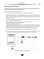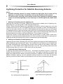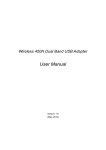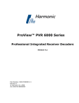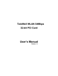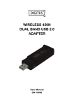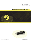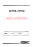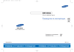
1
Thank you for purchasing Professional Receiver Decoder. This manual will help you to install, use and maintain the receiver. Please read this manual carefully before operating your unit and keep it for future reference. Warning & Note In this manual, pay special attention to the following marks that indicate hazardous situations. Warning: Alert user to the operation which could result in device damage or data loss, and the presence of a hazardous situation which could result in serious injury. Note: Remind user of presence of possible problems and information of any importance to help understand, use and maintain the installation. Note: The information in this user’s manual is subject to change without notice. The photos and function explanations in the manual are for reference. If any discrepancy exists, please refer to the entity. User’s Manual Safety Instruction Read following items carefully before operating this decoder. Installation This decoder should be installed horizontally. Unbalanced installation may cause damage. Install the decoder in a place with: good ventilation (leave space not less than 10cm around this decoder) no heat source (burning candle, radiator, heater, fireplace, amplifier, etc) suitable temperature against humidity (especially bathroom, kitchen, etc) no direct sunlight low vibration Maintenance Unplug this decoder from wall outlet before changing connections between this unit and other related equipments. Don’t unplug or insert signal, audio and video cables when this decoder is turned on. To avoid the risk of lightning strike, unplug power cord of the decoder from wall outlet in lightning storm. Unplug power cord from wall outlet when the unit is not used for a long time or damaged accidentally. Turn off this unit first, after 1 to 2 hours turn it on when move this decoder from a cold environment to a hot environment, vice versa. To avoid the risk of fire or electric shock, don’t expose this decoder to rain, splashing and don’t put object with liquid on this unit. Do not cover vents of this decoder with newspaper, table cloth, curtain, etc. Don’t put heavy objects on this decoder. Unplug power cord of this decoder from wall outlet before cleaning. To reduce damage, clean this unit with dry cloth. Do not let liquid and spray flow into this device to avoid serious damage. There is dangerous voltage in product enclosure. Do not remove the cover (or back) to avoid the risk of fire or electric shock. Power Socket and Power Cord The power socket should be available near the decoder and well grounded. Do not insert or pull out the power cord with wet hands to avoid electric shock or fire. Do not use damaged power cord. If power cord is damaged, contact your local dealer for replacement to avoid risk of fire or electric shock. Do not excessively bend the power cord, and do not place heavy objects on it, which could cause damage, electric shock or fire. Others The all-pole power switch of this decoder is on rear panel. Switch it to “I”, related equipment will connect with power supply. Switch it to “o”, related equipment will disconnect with power supply completely. I User’s Manual Connect Class I equipments with power socket which can protect grounding line. Only use accessories specified by the manufacturer, as other unsupported accessories may cause damage to the decoder. Warning Mark This mark appears on rear panel of this decoder, painted prominently in contrasting color to background. It consists of two graphical symbols and warning messages. The detailed specifications are as follows: Warning: To reduce the risk of electric shock, don’t remove the cover (or back). Equipment service and maintenance should be undertaken by qualified personnel. This symbol alerts user to the presence of uninsulated “dangerous voltage” in product enclosure that sufficient magnitude will constitute risk to person. This symbol reminds user of presence of important operation and maintenance instructions in literature accompanying this decoder. II User’s Manual Grounding Specification Warning: To secure user and device safety, all decoder and decoder cabinets must be connected with ground before turning them on. Grounding specifications are the following: 1. Grounding device consists of grounding lead-in cable and grounding body. 2. Grounding lead-in cable may be multiple copper wires or other zonal metal bar which section is more than 10mm. Grounding lead-in cable must be a whole cable without tie-in. Select the shortest distance to connect it with grounding body. Don’t bend it and do anticorrosive disposal. 3. Grounding body is metal object buried underground which is usually made of steel tube, angle iron or flat steel. Specifications are: Steel tube: Φ50mm and tube thickness should be not less than 3.5mm Angle iron: Not less than 50mm x 50mm x 50mm Flat steel: Not less than 40mm x 4mm Length of grounding body should be 1.5m to 2.5m. The depth of under ground should be more than 2m and grounding body should be buried under frozen soil layer in cold area. Backfill grounding pit with soil or impedance-reducing material such as salt. Make sure there are not blocks or building rubbishes in pit soil and infill soil according to layers. 4. Connection between grounding lead-in cable and grounding body must be welded. 5. To make sure that all cabinets are connected with ground securely, each cabinet must be connected with ground separately. The following diagram shows grounding process: III User’s Manual Lightning Protection for Satellite Receiving Antenna Notes: Satellite receiving antenna is usually installed at high place and is easily hit by lightning to cause damage. So lightning rod must be installed on the antenna. To prevent injury caused by pace voltage produced by lightning rod during lighting strike, do not install lightning rod over a passage or exit through which people often walk. 1. Making and installing wooden lightning rod Lightning rod consists of four parts: lightning receiving device (needle point of lightning rod), supporting pole, grounding lead-in cable and grounding body. Figure 1 shows a wooden lightning rod. Needlepoint is made of a thicker copper wire, iron wire or better still a thick iron rod. The supporting pole can be wooden or metal. Grounding lead-in cable can be made of thicker iron wire or other banded metal bar with its upper end connected to needlepoint and its lower end buried under ground for connecting with grounding body. The connection must be welded. The grounding lead-in cable must be a whole cable and select the shortest distance to connect it with grounding body. Try your best not to bend it. Grounding conduct is metal object buried under ground which is usually made of steel tube, angle iron or flat steel and its length should be 1m to 2m, buried not less than 2m under ground. Lightning rod and grounding body must be connected with ground separately. 2. Making and installing a metal lightning rod Lightning rod with metal supporting pole can induct lightning through the metal supporting pole without additional grounding lead-in cable. The needlepoint of the lightning rod is welded with the metal supporting pole. Grounding body buried under ground can be made of steel tube, angle iron, or steel needle which length should be 1m to 2m. The grounding body should be buried not less than 2m in a pit, in which some salt can be spread. 3. Protected area of lightning rod A lightning rod protects a pie slice area of 45° ~ 60° below it as shown in figure 2. A receiving antenna will be protected if it is in the pie slice area. The higher a lightning rod’s place, the bigger the protected area. Make sure that the antenna is installed in the protected area. The distance between lightning rod and protected antenna should be more than 5m because lightning rod and its lead-in cable can penetrate 2m to 3m air when inducted by lightning. IV User’s Manual Contents 1. Product Description ............................................................................................................. 3 1.1 Introduction ................................................................................................................... 3 1.2 Notice ............................................................................................................................ 3 1.3 Main Feature ................................................................................................................. 3 1.4 Front Panel ................................................................................................................... 4 1.5 Rear Panel .................................................................................................................... 4 2. Installation ............................................................................................................................ 6 2.1 System Connection ....................................................................................................... 6 2.2 Power on ....................................................................................................................... 6 2.3 Search Program ............................................................................................................ 7 2.4 Play Program ................................................................................................................ 7 3. Main Menu............................................................................................................................. 8 3.1 Status ............................................................................................................................ 8 3.2 Input .............................................................................................................................. 8 3.2.1 Input Source........................................................................................................ 8 3.2.2 *LNB Setting (DVB-S/S2 Tuner) ......................................................................... 8 3.2.3 Search................................................................................................................. 9 3.3 Service ........................................................................................................................ 10 3.3.1 Service Selection .............................................................................................. 10 3.3.2 Service Editing .................................................................................................. 10 3.4 Decrypt........................................................................................................................ 11 3.4.1 *CI Module ........................................................................................................ 11 3.4.2 *CA Module ....................................................................................................... 11 3.4.3 BISS Setting...................................................................................................... 12 3.5 *Output ........................................................................................................................ 12 3.5.1 *ASI Output ....................................................................................................... 12 3.5.2 *IP Output ......................................................................................................... 12 3.6 System ........................................................................................................................ 13 3.6.1 General Setting ................................................................................................. 13 3.6.2 Network Setting ................................................................................................ 14 3.6.3 AV Setting ......................................................................................................... 14 3.6.4 VBI Setting ........................................................................................................ 15 3.6.5 *Alarm Setting ................................................................................................... 15 3.7 Preset.......................................................................................................................... 17 3.7.1 Restore ............................................................................................................. 17 3.7.2 Reboot .............................................................................................................. 17 3.7.3 Configuration Save ........................................................................................... 17 3.7.4 Configuration Load ........................................................................................... 17 3.8 Identity......................................................................................................................... 17 4. *Scrambled Program.......................................................................................................... 18 4.1 *Insert Card ................................................................................................................. 18 4.2 Search Scrambled Program........................................................................................ 18 5. *ASI Cascade Setting ......................................................................................................... 18 6. Web Server Description..................................................................................................... 19 6.1 Introduction ................................................................................................................. 19 6.2 Web Page Description ................................................................................................ 19 1 User’s Manual 6.2.1 Status ................................................................................................................ 20 6.2.2 Identity .............................................................................................................. 20 6.2.3 System .............................................................................................................. 21 6.2.4 Decrypt.............................................................................................................. 21 6.2.5 *Input................................................................................................................. 23 6.2.6 Service .............................................................................................................. 23 6.2.7 *Output.............................................................................................................. 24 6.2.8 *Alarm ............................................................................................................... 25 6.2.9 Preset................................................................................................................ 25 7. Specification ....................................................................................................................... 28 8. Trouble Shooting................................................................................................................ 31 9. Acronym.............................................................................................................................. 32 2 User’s Manual 1. Product Description 1.1 Introduction This is a professional receiver decoder which offers a flexible solution that can be tailored to the needs of individual operators in a variety of applications. With configurable design, it supports HD/SD video decoding for multi-signal input. It has professional transmission functions with ASI, MPEGoIP, HDMI, CVBS, AES/EBU, XLR and other ports. Equipped with on-board dual common interfaces (CI), it can descramble multiple scrambled programs. With smart card, it can descramble programs scrambled by Irdeto CA. It is able to monitor the abnormal signals and trigger the relay alarm. User-friendly management style and programmable SNMP interface facilitate centralized management for multiple equipments. Note: There may be some hardware and software configuration differences for different models, please refer to the entity. 1.2 Notice The ports and functions marked with “*” need hardware and license support. For actual hardware configuration, please refer to the entity. You can select Main Menu → Identity → License to check license information. 1.3 Main Feature Professional transmission function *Support multi-signal input and compliant with DVB-S/S2, DVB-C, DVB-T, ABS-S and ASI standards *Dual-CI support numerous CAM types and compliant with EN 50221 standard *Irdeto CA supported *Support HD/SD video decoding in multiple formats *Support multiple transmission output interfaces, such as ASI, MPEGoIP, etc. *Support multiple video and audio output interfaces, such as HDMI, CVBS, AES/EBU, XLR, etc. *AES/EBU support PCM digital audio output User-friendly interface Support Web Server management and OSD management Support SNMP control by Ethernet *Alarm monitor supported Automatic recovery for latest system configuration due to unexpected power off Software upgrade via RS232 serial port or RJ45 3 User’s Manual 1.4 Front Panel Name Function 1. *SMART CARD Insert smart card 2. *CI SLOT Insert CAM card 3. INFORMATION Display status 4. SIGNAL STRENGTH Display signal strength 5. LOCK Bright if signal is locked 6/9. Move cursor left/right 7/8. Move cursor up/down 10. OK Display service information or confirm operation 11. MENU Display/exit from main menu or back to previous menu 1.5 Rear Panel 4 User’s Manual Name Function 1. Grounding Screw Used for grounding protection 2. ON/OFF Power switch 3. 100V-240V~ AC power supply port 4. LOOP THROUGH Loop output RF signal to another decoder 5. LNB IN/RF IN/ANT IN Input signal of DVB-S/S2, DVB-C, DVB-T, ABS-S, DMB-TH, etc 6. RS232 Serial port used for software upgrade, etc 7. *ALARM OUT Output high level (5V) when there is abnormal signal 8. *AES OUT Output AES3-id digital audio signal 9/10. *ETHERNET2/1 Connect to Ethernet 11. *ASI IN Input port for TS in ASI format, used for decoder cascading 12. *ASI IN LOOPOUT Loop output port for TS in ASI format 13/14. *ASI OUT1/2 Output port for TS in ASI format, used for decoder cascading 15/16. *CVBS1/2 Output CVBS video signal (VBI Teletext output port) 17/18. AUDIO-R/L Output right/left audio signal for monitoring 19. OSD CVBS Output CVBS video signal with OSD for monitoring 20. S-VIDEO Output Y/C video signal to TV 21. *HDMI Output video and audio signal to TV (support HD output) 22. *RIGHT ANALOG Output right analog XLR audio signal XLR AUDIO 23. *LEFT XLR AUDIO ANALOG Output left analog XLR audio signal 5 User’s Manual 2. Installation 2.1 System Connection Connect satellite dish, AV devices and other related devices referring to following diagram. Notes: Before connecting, please power off all connected devices. If some cables in above diagram are not included in the package, user can self-configure as needed. Please connect AV cables according to color. Used for monitoring and debugging, OSD CVBS output can not serve as main signal output for modulators or other AV devices. CVBS output is the main signal output for modulators or other AV devices. You can connect this decoder with modulators via XLR port or RCA port. You can select different tuner to receive appropriate signals, such as cable signal and terrestrial signal. If you encounter any problem during the connections, please contact your local dealer. 2.2 Power on 1. Connect one end of power cord to the decoder. 2. Connect the other end of power cord to power socket. 3. Turn on the decoder, system initializes and start-up OSD is shown on TV screen. Note: Please turn on your TV and switch it to AV mode. 6 User’s Manual 2.3 Search Program After initialization, system will search programs automatically according to the set frequency parameters. After searching, program will be played automatically, and the channel number is shown on front panel. Note: If frequency parameters are set wrongly, you can modify parameters to search programs manually. For more details, please refer to 3.2.3 Search. 2.4 Play Program Select Main Menu → Service → Service Select and press OK key to enter service info window, or press OK key directly in non-menu mode to enter. You can select programs to play. If needed, you can set PID values directly to play program. For more details, please refer to 3.3.1 Service Selection. 7 User’s Manual 3. Main Menu In non-menu mode, press MENU key to display main menu that consists of following items: Status Input Service Decrypt Output System Preset Identity Select items with keys and press OK key to enter sub-menu. Note: Please operate according to key instructions on screen. 3.1 Status Status includes general information, stream information, AV information and IP information. General Info: Status and Decoding Service information. Stream Info: TS ID, Org_Network ID, etc. AV Info: Resolution, Analog Mixer, VBI select, etc. *IP Info: Information related to IP output, including Dst IP and Dst Port. keys: Select item OK key: Display information MENU key: Back to previous menu 3.2 Input 3.2.1 Input Source You can set input source. *Input Select: Press keys to select ASI or Tuner. *Max Rate: If DVB-S/S2 tuner is configured for this decoder and “Input Select” is set to “Tuner”, press keys to select a proper max. rate (48Mbps, 72Mbps, 96Mbps, 108Mbps or 216Mbps). After setting, move cursor to “apply” and press OK key to confirm. 3.2.2 *LNB Setting (DVB-S/S2 Tuner) If DVB-S/S2 tuner is configured for this decoder, you can set LNB parameters. 8 User’s Manual LNB Type: Press keys to select Single or Universal according to your LNB. LNB Power: Press keys to select 13V (vert), 18V (horiz) or OFF. keys to select ON or OFF according to connection of 22k switch. If “LNB LNB 22k: Press Type” is set to “Universal”, 22k switch will operate automatically. and keys to set low frequency of LNB and press OK key to Low Freq. (MHz): Press confirm. High Freq. (MHz): If “LNB Type” is set to “Universal”, please set high frequency of LNB. Please refer to above operation. After setting, move cursor to “apply” and press OK key to confirm. 3.2.3 Search Notes: Don’t turn off the decoder during searching. Do not modify the frequency parameters arbitrarily, otherwise it will affect the search. 3.2.3.1 Tuner Setting If “Input Select” is set to “Tuner”, tuner setting window will be displayed. You can modify frequency parameters to search programs manually, and view tuner status, including signal strength, signal quality and error rate. DVB-S/S2 Tuner and keys to set Down Freq. (MHz): Press down frequency and press OK key to confirm. and keys to Symbol Rate (KS/s): Press set symbol rate and press OK key to confirm. DVB-C Tuner and keys to set Frequency (MHz): Press frequency and press OK key to confirm. and keys to Symbol Rate (KS/s): Press set symbol rate and press OK key to confirm. keys to select Modulation (QAM): Press QAM16, QAM32, QAM64, QAM128 or QAM256. DVB-T Tuner and keys to set Down Freq. (KHz): Press down frequency and press OK key to confirm. BandWidth (M): Press keys to select 6M, 7M or 8M. keys to select ON or OFF. LNB Power: Press After setting, move cursor to “Search” and press OK key to search programs according to the set frequency parameters. After searching, program will be played automatically. 9 User’s Manual 3.2.3.2 ASI Setting If “Input Select” is set to “ASI”, ASI setting window will be displayed. You can search programs manually, and view ASI status, including signal strength, signal quality and error rate. Move cursor to “Search” and press OK key to search programs. After searching, program will be played automatically. 3.3 Service 3.3.1 Service Selection In non-menu mode, you can press OK key to enter this window. You can view program information, and select programs to play. If needed, you can set PID values directly to play program. 3.3.1.1 Play Program keys: Select program OK key: Play program 3.3.1.2 PID Play Move cursor to “PID Play” and press OK key to enter service PID window. Video PID: Press and keys to set video PID value and press OK key to confirm. Audio PID: Set audio PID value. Please refer to above operation. PCR PID: Set PCR PID value. Please refer to above operation. Teletext PID: Set Teletext PID value. Please refer to above operation. After setting, move cursor to “apply” and press OK key to play program according to the set PID values. 3.3.2 Service Editing You can delete programs. keys: Select program OK key: Set/cancel deletion After setting, move cursor to “delete” and press OK key to confirm. 10 User’s Manual 3.4 Decrypt 3.4.1 *CI Module 3.4.1.1 CI Information You can view version and provider of CAM card and detailed CA card information. keys: Select item OK key: Display information MENU key: Back to previous menu 3.4.1.2 SLOT1/SLOT2 Setting You can set one or more scrambled programs to be descrambled for output via SLOT1 or SLOT2. keys: Select program OK key: Set/cancel descrambling After setting, move cursor to “Apply” and press OK key to confirm. Notes: If one program has been set to be descrambled for output in current slot, its background will become blue. If one program’s background is gray, it means this program has been set to be descrambled for output in another slot, and can not be re-set. The total number of programs that are set to be descrambled for output can not exceed the maximum supported by this decoder. The actual number of the descrambled programs needs support of CAM card. If no program is set to be descrambled for output, system will only descramble current program. If any program is set to be descrambled for output, other programs cannot be played. 3.4.2 *CA Module 3.4.2.1 Smart Card You can view smart card information, such as status, number, type, etc. 3.4.2.2 SoftCell Service You can view softcell service status, such as handle, name, source TS, etc. OK key: Display ECM status or EMM status. ECM Status You can view ECM status, such as global service 11 User’s Manual status, service handle, etc. EMM Status You can view EMM status, such as global status, service status, EMM source, etc. 3.4.3 BISS Setting You can select BISS-1 or BISS-E descrambling if needed. BISS Type: Press keys to select NONE, BISS-1 or BISS-E. If BISS descrambling is not needed, please select “NONE”. SW (0x): If “BISS Type” is set to “BISS-1” or “BISS-E”, and keys to set SW (0x) value press (hexadecimal) and press OK key to confirm. Injected ID (0x): If “BISS Type” is set to “BISS-E”, and keys to set injected ID (0x) value press (hexadecimal) and press OK key to confirm. After setting, move cursor to “apply” and press OK key to confirm. 3.5 *Output 3.5.1 *ASI Output You can set ASI output source and ASI output format. *ASI Out Select: Press keys to select ASI IN, Tuner, CAM or OFF. If “ASI IN” is selected, ASI OUT port will output TS that is input from ASI IN port. If “Tuner” is selected, ASI OUT port will output TS that is input from LNB IN port. If “CAM” is selected, ASI OUT port will output TS that is input descrambled by CAM card. If “OFF” is selected, there will be no output from ASI OUT port. Note: In order to avoid output abnormity, this setting should be consistent with the set input source. But “CAM” can be selected without such restriction. keys to select 188 or 204. The default is “188”. ASI Out Format: Press After setting, move cursor to “apply” and press OK key to confirm. 3.5.2 *IP Output 3.5.2.1 General Setting You can set general parameters of IP output. keys to select ON or OFF. *Eth Backup: Press The default is “OFF”. Note: This setting is only available when “IP Out Enable” of Ethernet2 is set to “ON”. keys to select UDP number (4 UDP Num: Press ~ 7). The default is “7”. Note: For MPTS output, the recommended UDP number is over 5, otherwise system 12 User’s Manual performance will be affected according to bit-rates. Protocol: Press keys to select UDP or RTP. The default is “UDP”. keys to select ON or OFF. The default is “OFF”. Filter Null Packet: Press Note: If “ON” is selected, system will automatically filer null packet with PID value of “8191”. After setting, move cursor to “apply” and press OK key to confirm. 3.5.2.2 Ethernet1 Output You can set IP output parameters of Ethernet1. IP Out Enable: Press keys to select ON or OFF. The default is “OFF”. If “ON” is selected, please continue following setting: keys to select MPTS or IP Out Type: Press SPTS. The default is “MPTS”. Channel: If “IP Out Type” is set to “SPTS”, press keys to select a channel. Service: If “IP Out Type” is set to “SPTS”, press keys to select a program. Dst MAC: Display destination MAC address automatically, and can not be set. Dst IP: Press and keys to set destination IP address and press OK key to confirm. The default is multicast address (e.g. 227.0.1.1). and keys to set destination Dst Port: Press port and press OK key to confirm. After setting, move cursor to “apply” and press OK key to confirm. 3.5.2.3 *Ethernet2 Output If “Eth Backup” is set to “OFF”, the programs output from Ethernet2 are the same as those from Ethernet1. But you can set destination IP and port. For detailed operations, please refer to 3.5.2.2 Ethernet1 Output. Note: If “Eth Backup” is set to “ON”, this setting is not available, and Ethernet2 works as backup of Ethernet1 with all the parameters the same as those of Ethernet1. If Ethernet1 does not work, Ethernet2 will automatically substitute for Ethernet1 to work. 3.6 System 3.6.1 General Setting You can set general parameters of system. Language: Press keys to select a language for menu. The default is “English”. After setting, move cursor to “apply” and press OK key 13 User’s Manual to confirm. 3.6.2 Network Setting You can set network parameters. *Note: If “Eth Backup” is set to “ON”, network parameters of Ethernet2 are the same as those of Ethernet1, and can not be set. *NIC Select: Press keys to select Ethernet1 or Ethernet2. MAC Address: Display MAC address automatically, and can not be set. and keys to set IP IP Address: Press address and press OK key to confirm. NetMask: Set mask. Please refer to above operation. GateWay: Set gateway. Please refer to above operation. After setting, move cursor to “apply” and press OK key to confirm. The default network parameters of Ethernet1: IP Address: 192.168.1.1 NetMask: 255.255.255.0 GateWay: 192.168.1.254 *The default network parameters of Ethernet2: IP Address: 192.168.2.1 NetMask: 255.255.255.0 GateWay: 192.168.2.254 3.6.3 AV Setting You can set AV parameters. Resolution: Press keys to select a proper resolution (Auto, NTSC, PAL-BDGHI, PAL-M, SECAM, 720P60, 720P59.94, 720P50, 1080I60, 1080I59.94 or 1080I50). Note: HD resolution is only applicable to HD series decoders. keys to select ON or OFF. PCR Synchr: Press keys to select a proper Aspect Ratio: Press aspect ratio (Auto, 4:3 or 16:9). keys to select Letter Box AR Conversion: Press or Pan Scan. keys to select Uncompress or Compressed. If “Compressed” is *Digital Audio: Press selected, AC3 will be output from AES OUT port. keys to select Stereo, Left, Right or Mono. Analog Mixer: Press keys to adjust volume. Volume (0 ~ 31): Press After setting, move cursor to “apply” and press OK key to confirm. 14 User’s Manual 3.6.4 VBI Setting You can set VBI parameters. keys to select TeleText, VBI Select: Press CloseCaption or OFF. After setting, move cursor to “apply” and press OK key to confirm. 3.6.5 *Alarm Setting You can set alarm parameters, so that system will response with related actions according to the set parameters when an abnormity occurs. 3.6.5.1 General Setting keys to select OFF or ON. Master Switch: Press The default is “OFF”. keys to select OFF or ON. Auto Recover: Press The default is “OFF”. IP Address of Trap: The default is “192.168.1.2”. Note: If there is an alarm, system will automatically send alarm information to the set IP address via SNMP Trap. After setting, move cursor to “Apply” and press OK key to confirm. 3.6.5.2 Alarm Item Signal Abnormity keys to select Lock state, Strength or Quality. Item Select: Press Alarm Switch: Press keys to select OFF or ON. The default is “OFF”. Alarm Level: Press keys to select an alarm level. The default is “Level-1”. and keys to set Critical Value: Press critical value and press OK key to confirm. Note: If “Item Select” is set to “Lock state”, This value denotes signal interruption duration (seconds). If set to "Strength", it denotes range of signal strength change (dB). If set to "Quality ", it denotes range of signal quality change (dBm). After setting, move cursor to “Apply” and press OK key to confirm. Stream Abnormity Item Select: Press CC Error. Alarm Switch: Press The default is “OFF”. Alarm Level: Press keys to select Sync Error or keys to select OFF or ON. keys to select an alarm level. 15 User’s Manual The default is “Level-1”. Critical Value: Press and keys to set critical value and press OK key to confirm. Note: This value denotes number of alarm items occurred within 10 seconds. After setting, move cursor to “Apply” and press OK key to confirm. Decode Abnormity keys to select Vid Overflow, Item Select: Press Vid Underflow, Vid Error, Aud Underflow or Aud Error. Alarm Switch: Press keys to select OFF or ON. The default is “OFF”. keys to select an alarm level. Alarm Level: Press The default is “Level-1”. and keys to set Critical Value: Press critical value and press OK key to confirm. Note: This value denotes number of alarm items occurred within 10 seconds. After setting, move cursor to “Apply” and press OK key to confirm. Network Abnormity keys to select Eth1 Link *Item Select: Press State or Eth2 Link State. keys to select OFF or ON. Alarm Switch: Press The default is “OFF”. keys to select an alarm level. Alarm Level: Press The default is “Level-1”. After setting, move cursor to “Apply” and press OK key to confirm. 3.6.5.3 Alarm Action keys to select an alarm level. The default is “Level-1”. Alarm Level: Press *Buzzer Output: Press keys to select OFF or ON. The default is “OFF”. Note: During buzzer output, relay will also output voltage. Front Panel Display: Press keys to select OFF or ON. The default is “OFF”. keys to select OFF or *Video Color Bar: Press ON. The default is “OFF”. keys to select OFF or ON. *ASI Cutoff: Press The default is “OFF”. keys to select OFF or *MPEGoIP Cutoff: Press ON. The default is “OFF”. After setting, move cursor to “Apply” and press OK key to confirm. 16 User’s Manual 3.7 Preset 3.7.1 Restore Warning: This function will restore system settings to factory default and erase all programs. Move cursor to “Restore” and press OK key, a message box pops up for confirmation. Select “Confirm” and press OK key to confirm or select “Cancel” and press OK key to cancel the operation. 3.7.2 Reboot You can reboot system by this operation. Move cursor to “Reboot” and press OK key, a message box pops up for confirmation. Select “Confirm” and press OK key to confirm or select “Cancel” and press OK key to cancel the operation. 3.7.3 Configuration Save You can save current configuration (e.g. LNB setting, AV setting, etc) by this operation. Move cursor to “Config Save” and press OK key, a message box pops up for confirmation. Select “Confirm” and press OK key to confirm or select “Cancel” and press OK key to cancel the operation. 3.7.4 Configuration Load You can load the last saved configuration by this operation. Move cursor to “Config Load” and press OK key, a message box pops up for confirmation. Select “Confirm” and press OK key to confirm or select “Cancel” and press OK key to cancel the operation. 3.8 Identity You can view product information, hardware information and software information. OK key: Display license information (Display all the functions supported by this decoder, such as MPEG4 decoding, MPEGoIP, etc) 17 User’s Manual 4. *Scrambled Program With CAM card and smart card, you can enjoy various scrambled programs authorized by program providers. 4.1 *Insert Card *Insert CAM Card 1. Insert the CAM card into the CI slot on the left side of front panel according to arrow direction. 2. Face the side with electronic chip upwards and insert the smart card into the CAM card horizontally according to arrow direction. *Insert Smart Card Smart card slot is on the left side of front panel. Face the side with electronic chip downwards and insert the smart card into the smart card slot horizontally according to arrow direction. 4.2 Search Scrambled Program You can modify frequency parameters according to actual tuner type and search programs manually. For more details, please refer to 3.2.3 Search. 5. *ASI Cascade Setting ASI cascade means serially connecting two or more decoders via ASI IN and ASI OUT ports, so as to realize multi-program descrambling in one TS. Set cascade as follows: Set Hardware Cascade Connect ASI OUT port of a decoder to ASI IN port of another decoder with a BNC cable. Repeat this step to set more cascades. Set Software Cascade If you want to set TS descrambled by decoder 1 and output from its ASI OUT port as an input stream of ASI IN port of decoder 2, please set “ASI Out Select” to “CAM” in “Main Menu → Output → ASI Output” window of decoder 1, and set “Input Select” to “ASI” in “Main Menu → Input → Input Source” window of decoder 2. Cascade Diagram 18 User’s Manual 6. Web Server Description 6.1 Introduction With the embedded Web Server in decoder, user can realize remote monitoring and function setting for professional receiver decoder. User can access decoder from PC through network via a browser, and submit data through the interactive page to monitor the decoder. One PC can control more than one decoder simultaneously. This function greatly improves operability of decoder, and facilitates management. Notes: Connect decoder to Ethernet with RJ45 data line. Before operation, please set IP address of decoder (e.g. http://192.168.1.1) in “Main Menu → System → Network Setting” window according to network environment. The IP address of decoder and the computer should be set in the same network segment or IP sub-net. Recommended browser version is “IE6.0” or above, and screen resolution of computer “1024 x 768”. 6.2 Web Page Description Open the browser, and input the set IP address to enter web page. Note: The default IP address of Ethernet1 is “http://192.168.1.1”, and *Ethernet2 “http://192.168.2.1”. The page consists of function navigation area, information area and page title area. Function navigation area provides quick navigation for Status, Identity, System, Decrypt, Input, Service, Output, Alarm and Preset. Information area provides viewing or setting of actual features. Page title area displays product description, etc. Note: Web page may vary with different models, tuner types and operation systems. 19 User’s Manual 6.2.1 Status Status page displays input status, stream information, output status and decoding service. You can refresh status manually, or set automatic refreshing. Input status includes current input source, lock status, etc. Stream information includes input rate, TS ID, original network ID, etc. Output status displays status of two Ethernet ports, such as MAC address, IP address, link state, etc. Decoding service includes service name, service ID, service type, etc. 6.2.2 Identity Identity page displays version information and license information. Version information includes product information and software/hardware information, such as product name, logic version, etc. License Information includes decoding configuration, input/output configuration, etc. 20 User’s Manual 6.2.3 System System page includes language setting and Ethernet parameter setting. 6.2.4 Decrypt *Decrypt page includes CI setting (or CA status) and BISS setting. *CI Setting CI setting provides CA card information viewing and multi-descrambling setting. 21 User’s Manual *CA Status CA Status provides smart card status and softcell service status viewing. 22 User’s Manual BISS Setting BISS setting supports BISS-1 and BISS-E descrambling. 6.2.5 *Input Input page displays input status. You can set input parameters. Input status includes current input source, lock status, input rate, etc. *You can set input source (ASI or Tuner). If “Tuner” is selected, please continue RF input setting. 6.2.6 Service Service page displays information of all the searched programs. You can select programs to play or set PID values directly to play program. If needed, you can set AV parameters and VBI parameters. 23 User’s Manual 6.2.7 *Output Output page includes ASI output setting and IP output setting of two Ethernet ports, supporting MPTS and SPTS. Note: IP output of Ethernet2 needs license support. 24 User’s Manual 6.2.8 *Alarm Alarm page includes general setting, alarm item setting and alarm action setting. 6.2.9 Preset On Preset page, you can restore default, reboot system, save current configuration, load the last saved configuration and update software. Restore & Reboot Click “Restore” or “Reboot” button, a message box pops up for confirmation. Click “OK” button to confirm or click “Cancel” button to cancel the operation. 25 User’s Manual Configuration Save & Load Configuration Save: Click “Save” button, a message box pops up for confirmation. Click “Save” button and select a folder to save current configuration (e.g. RF setting, AV setting, etc). Configuration Load: Click “Browse” button and select a configuration file, then click “upload” button, a message box pops up for confirmation. Click “OK” button to confirm or click “Cancel” button to cancel the operation. 26 User’s Manual Software Update Click “Browse” button and select an update file, then click “update” button, a message box pops up for confirmation. Click “OK” button to confirm or click “Cancel” button to cancel the operation. Notes: Force update is supported. If “force update” is not selected, the version of the selected update software should be higher than the version of current software. The hardware version of the selected update software should be the same as the version of current hardware. 27 User’s Manual 7. Specification DVB-S Input Frequency 950 ~ 2150MHz Symbol Rate 2.0 ~ 45MS/s Input Impedance 75Ω LNB Power 13V/18V, Imax=400mA (LNB automatic short circuit protection) Control Switch 0/22k switch (support Universal LNB) Standard EN300 421 DVB-S2 (optional) Input Frequency 950 ~ 2150MHz Symbol Rate 2.0 ~ 45MS/s (QPSK), 5.0 ~ 37MS/s (8PSK) Modulation Mode QPSK, 8PSK Standard EN302 307 DVB-C (optional) Input Frequency 47 ~ 862MHz Symbol Rate 2.0 ~ 7.0MS/s QAM Demodulation 16/32/64/128/256 Standard EN300 429 DVB-T (optional) Input Frequency 174 ~ 862MHz Bandwidth 6M, 7M, 8M FEC 1/2, 2/3, 3/4, 5/6, 7/8, Automatic Demodulation QPSK, 16QAM, 64QAM Standard EN300 744 Video Decoding Standard SD series: MPEG-2 MP@ML, MPEG-4 ASP, MPEG-4 AVC/H.264, MP@L3, MP@L4 HD series: MPEG-2 MP@ML, MPEG-2 MP@HL, MPEG-4 ASP, MPEG-4 AVC/H.264, MP/HP@L3, [email protected], [email protected] Audio Decoding Standard MPEG-1 Layer I & II, MPEG-2, AC3 28 User’s Manual Micro-Processor & Memory Working Frequency 450MHz Flash 8MB DDR SDRAM 2 × 128MB Front Panel Display 4-segment LED displays channel number and status 10-level LED displays signal strength Key 6 keys (Up, Down, Left, Right, MENU, OK) *CA Interface Smart card slot × 1 *CI Interface *Conditional Support CI slot × 2 Access Irdeto, NDS VideoGuard, MediaGuard, Cryptowork Viaccess, Nagravision, Canal+, Rear Panel LNB IN/ RF IN/ANT IN LOOP THROUGHT DVB-S/S2: F type female × 1 DVB-C: F type female × 1 DVB-T: IEC type female × 1 DVB-S/S2: F type female × 1 DVB-C/DVB-T: IEC type male × 1 RCA Output RCA × 3 (Audio-Left × 1, Audio-Right × 1, OSD monitor video × 1) Y/C Output S-Video × 1 *ASI Interface BNC port × 4 (ASI IN × 1, ASI OUT × 2, ASI IN LOOPOUT × 1) *AES OUT BNC port × 1 *ALARM OUT BNC port × 1 *Main Video Output BNC port × 2 (video without OSD) *HDMI Output HDMI port × 1 RS232 Interface DB-9 female × 1 *Ethernet Interface RJ45 × 2 *Analog Output XLR port × 2 XLR Audio Power Supply Input Voltage 100V-240V~ 50/60Hz Power Consumption 35W max. 29 User’s Manual Physical Size 435mm (L) × 257mm (W) × 44mm (H) Chassis 1RU (19″) Weight 4kg Operation Temperature 0℃ ~ +40℃ Storage Temperature -40℃ ~ +60℃ Storage Humidity ≤93% 30 User’s Manual 8. Trouble Shooting DISPLAY on front panel is off 1. Power cord is disconnected. Make sure power cord is plugged into a proper power socket. 2. The receiver is turned off. Turn it on. No signal 1. Satellite dish doesn’t point at the satellite. Adjust dish and check signal level. 2. LNB frequency parameters are set wrongly. Set correct frequency parameters. 3. No power supply to LNB. Set “LNB Power” to “13V (vert)” or “18V (horiz)” in “Main Menu → Input → LNB Setting” window. 4. Signal cable is disconnected. Connect signal cable correctly. 5. There is no signal from front-end. Try again when signal is available. No sound 1. Audio cable is disconnected or incorrectly connected. Connect audio cable correctly. 2. Volume is set to minimum. Increase volume to a proper level. 3. Audio parameter is set wrongly. Set a proper audio parameter. No picture 1. Video cable is disconnected or incorrectly connected. Connect video cable correctly. 2. The receiver is in radio mode. Switch it to TV mode if you need. Video and audio mismatch, or absonant sound Audio parameter is set wrongly. Select a proper audio parameter. *Teletext information is not available 1. Video is not output from main video output port. Connect video cable to main video output port. 2. “VBI Select” is set to “OFF” or “CloseCaption”. Set “VBI Select” to “Teletext” in “Main Menu → System → VBI Setting” window. Poor quality picture 1. Weak signal. Connect signal cable securely. 2. Video is not output from main video output port. Connect video cable to main video output port. *No video output from cascaded decoder “Input Select” is not set to “ASI”. Set “Input Select” to “ASI” in “Main Menu → Input → Input Source” window. Cannot play program *1. Smart card or CAM card is inserted incorrectly. Insert smart card and CAM card correctly. 2. TS is changed. Restore default and search program again. *MPEGoIP data is not available 1. “IP Out Enable” is set to “OFF”. Set “IP Out Enable” to “ON” in “Main Menu → Output → IP Output → Ethernet1/2 Output” window. 31 User’s Manual 2. Destination IP and port are set wrong. Set correct destination IP and port. Abnormity occurs during operation, such as only menu background displayed on screen, and keys invalid. Keep pressing MENU key for 2 to 3 seconds until system resumes to full screen display mode. Decoder does not work Decoder is installed in a place with heat source and bad ventilation. Move it to a well ventilated place. Note: If you cannot solve the problems after referring to this trouble shooting, please contact your local dealer. 9. Acronym ASI CA CC CI CVBS DiSEqC DVB FTA HDMI HDTV LCN LED LNB MUX NIT OSD OTA PCR PID QAM RCA RF SDTV SNMP S/P DIF S-VIDEO TS UHF URL VBI Asynchronous Serial Interface Conditional Access Closed Caption Common Interface Composite Video Broadcast Signal Digital Satellite Equipment Control Digital Video Broadcasting Free to Air High Definition Multimedia Interface High Definition Television Logical Channel Number Lighting Emitting Diode Low Noise Block Multiplexer Network Information Table On Screen Display Over the Air Program Clock Reference Packet Identifier Quadrature Amplitude Modulation Radio Corporation of America Radio Frequency Standard Definition Television Simple Network Management Protocol Sony/Philips Digital Interface Format Separate Video Transport Stream Ultra-High Frequency Uniform Resource Locator Vertical Blanking Interval 32