1
RASSP Manufacturing Interface
(RASSP-MI) Appnote
Abstract
In order to remain globally competitive, it is critical that organizations establish processes that allow them to
adapt to an ever changing market place. This need for agility is particularly pronounced for organizations
involved in the design and/or manufacture of complex products. An agile manufacturing interface that allows
design and manufacturing organizations to interact in a highly automated and effective manner is essential to
realizing the RASSP objectives. This capability allows designers to quickly assess the level of compatibility
between a design and a manufacturing facility, while simultaneously providing manufacturers with the ability
to effectively interact with a diverse variety of design organizations. The RASSP Manufacturing Interface has
been designed to enable this agility and provide the mechanisms necessary to help ensure first-pass
manufacturing success.
The essential role that virtual concurrent engineering plays in the realization of agility is examined in this
Application Note. Virtual Concurrent Engineering is defined to be the application of concurrent engineering
concepts and principles amongst teams and organizations that have formed a temporary "virtual" organization
for the purpose of accomplishing some task. The members of a virtual organization are generally not
physically co-located. The definition of concurrent engineering assumed in this document is the effective and
efficient sharing of information between different groups working at different life-cycle stages of a product
throughout the life of that product from conception to retirement. The principle goal of virtual concurrent
engineering is to provide the information sharing infrastructure necessary to enable the formation of virtual
organizations and to provide them with the robust DFx mechanisms (Design For x where x = cost,
manufacturability, testability, etc.) they need in order to develop high quality products in a timely, cost
effective manner.
Purpose
This appnote discusses the operational characteristics of the RASSP Manufacturing Interface as well as the
experience gained in establishing an agile manufacturing interface to support the RASSP process. The results
achieved from the operation of the RASSP Manufacturing Interface are presented. These results, realized in a
production environment, include a 10x reduction in the time required to transition from design to
manufacturing set-up, and a reduction in rework of complex Printed Circuit Assemblies of up to 80%.
Roadmap
1.0 Introduction
2.0 Technology Description
2.1 Input Interfaces
2.1.1 Support for Mentor Graphics Corporation's Board Station
2.1.1.1 Mentor Board Station PCA Design File Preparation using
get?mentor?design
2.1.1.2 Mentor Board Station PCA Design Data Conversion Using mentor2step
2.1.1.3 Mentor Board Station PCA Design Data Conversion Using mentor2ap210
2.1.2 Support for EDIF 4 0 0 Level 0
2.2 Output Interfaces
2.3 Manufacturing Resource Editor (MRE)
2.3.1 MRE Operational Overview
2.3.1.1.7 Human Resources
2.3.2 Data Population Constraints
2.3.3 Variable and Fixed Cost Computations
2.4 Producibility Analysis
2.5 Rule Definition/Execution Facility (RD/EF)
2.5.1 Rules Definition Facility
2.5.2 Rules Execution Facility
2.6 Web-based interface
3.0 RASSP Manufacturing Interface Usage Scenarios
3.1 Remote, Facility Specific Producibility Analysis
3.2 Capturing Manufacturing Facility Knowledge
3.3 Automation Enabled by Industry Standards
4.0 LMC Installation
4.1 Process Improvements
4.2 Payback Analysis
5.0 Summary
6.0 References
Approved for Public Release; Distribution Unlimited Dennis Basara
Next: 2 Technology Description Up: Appnotes Index Previous:Appnote RMI Index
RASSP Manufacturing Interface (RASSP-MI)
Appnote
1.0 Introduction
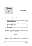
The RASSP Manufacturing Interface (RASSP-MI), developed by SCRA's Advanced Technology Institute and Lockheed Martin's
Advanced Technology Labs (LMC-ATL), enables significant reductions in the time and cost required to develop and manufacture
electronic systems while yielding improvements in product quality. This is achieved by providing novel enterprise integration and
collaboration capabilities that enable distributed, multidisciplinary concurrent engineering teams to work together effectively within
a virtual enterprise. Figure 1-1 illustrates this concept.
Figure 1 - 1: RASSP Manufacturing Interface Concept
The RASSP-MI is composed of several elements that implement the overall capability described. A World Wide Web (WWW)
based interface provides users external to the manufacturing facility hosting the RASSP-MI with easy to use, robust access to the
capabilities of the RASSP-MI. An external user will typically be a Printed Circuit Assembly (PCA) designer interested in
examining the producibility characteristics of a PCA design early in the physical layout life-cycle design stage. The designer can
easily and securely transmit a PCA design to the RASSP-MI, then use the Producibility Analyzer (PA) and the Rule Execution
Facility (REF) to determine how compatible the PCA design is with the hosting manufacturing facility. Thus, the PCA designer
can quickly and easily identify manufacturing facility-specific producibility issues with a design once preliminary component
layout has occurred. By continuing to examine a design's producibility and make corrections as necessary as it matures towards
completion, it is possible to eliminate all producibility issues before the design is passed on to production, and thereby achieve
first-pass production success.
By making use of robust, widely-accepted standards such as EDIF 4 0 0[Lau96] and STEP AP210[ISO96], the RASSP-MI
ensures that the requirements of predictability, completeness, consistency, and semantic correctness in the exchange of product
data are met. In addition, the standards-based approach has made it possible to simultaneously utilize information from a variety of
domains, enabling advanced producibility analyses that could not be performed previously.
The Manufacturing Resource Editor (MRE) is used by manufacturing engineers to capture the structure, characteristics, and
limitations of a manufacturing facility in knowledge-base form. This information, combined with the intelligent product data
acquired from the PCA designer, make the advanced producibility analysis functions performed by the PA and REF possible. The
Rule Definition Facility (RDF) provides a framework within which a manufacturing engineer can capture process knowledge in the
form of rules. This knowledge capture tool is designed such that computer programming skills are not required to operate it
effectively, thereby making the tool accessible to a broad spectrum of manufacturing engineers, not just those with a background in
computer science. The process knowledge captured with the RDF is used by the REF, which executes it much like a program on
product and process data.
Finally, the RASSP-MI provides support for Mitron's CIMBridge manufacturing support software, which provides a variety of
functions such as process planning and Numeric Control (NC) program generation. It also includes the Producibility Analyzer,
which was commercialized by Mitron during the course of the RASSP program.
This Application Note presents further information on the operational details and benefits of the RASSP-MI components just
introduced. In addition, the results achieved by an implementation of the RASSP-MI in a production environment are presented.
Section 2 presents detailed operational characteristics of the various components that make up the RASSP-MI. Section 3 presents
usage scenarios that illustrate how to effectively use the RASSP-MI to support common activities. Section 4 presents results
achieved by a Lockheed Martin manufacturing facility using the RASSP-MI. Section 5 concludes with a summary.
Next: 2 Technology Description Up: Appnotes Index Previous:Appnote RMI Index
Approved for Public Release; Distribution Unlimited Dennis Basara
Next: 3 RASSP Manufacturing Interface Usage Scenarios Up: Appnotes Index Previous: 1 Introduction
RASSP Manufacturing Interface (RASSP-MI)
Appnote
2.0 Technology Description
The following Sections discuss both the purpose and operational details of the components that make up the RASSP-MI.
2.1 Input Interfaces
The following Sections discuss two interfaces that import electronic design data into the RASSP-MI that have been developed. The
first imports design data created by Mentor Graphics Corporation's Board Station PCA design product. The second imports design
data represented by the EDIF 4 0 0 (Level 0) standard. The mechanism by which Mentor Board Station and EDIF 4 0 0 are
supported is by converting these data representations into the STEP AP210 standard PCA design data representation. STEP
AP210 is the representation used internally by RASSP-MI components. The same approach can be used to add support to the
RASSP-MI for other electronic CAD (ECAD) systems and standards as necessary.
2.1.1 Support for Mentor Graphics Corporation's Board Station
Support for PCA design information created using Mentor's Board Station product is provided by The Mentor Board Station to
STEP Application Protocol 210 (AP210) EXPRESS Driven Data Converter [Hin94]. This Section discusses the operation of this
data converter in detail. Figure 2.1.1-1 presents a data flow diagram that illustrates how the data converter operates and how it fits
into the overall RASSP-MI system. The definition of "RASSP Manufacturing Interface Core Capabilities" is all functions of the
RASSP-MI that perform operations other than facilitating input and output.
Figure 2 - 1: Mentor Board Station Support in the RASSP Manufacturing Interface
The Mentor Board Station Interface is implemented by the mentor2step executable. This program is assisted by two C-shell
scripts that collect Mentor Board Station data files and simplify the user interface for the most common usage of the data converter.
The remainder of this Section discusses the operation of these components in detail.
2.1.1.1 Mentor Board Station PCA Design File Preparation using get?mentor?design
The get?mentor?design script prepares Mentor Board Station PCA design files for use by mentor2step . The calling syntax of
this command is as follows:
get?mentor?design [design_directory_name]
This command acquires and renames Mentor Board Station PCA design files. The files are acquired from
<design_directory_name >, renamed, and placed in the current working directory. Once these operations are complete, the PCA
design data is accessible to mentor2step .
The get-mentor-design script acquires the following MGC PCA design files from the <design_directory_name>/pcb directory:
comps.comps_<max >, traces.traces_<max>, layers.layers_<max>, nets.nets_<max>, tech.tech_<max>,
gates.gates_<max>, testpoints.testpoints_<max>, ../ascii_parts_file
These files normally occur under the pcb directory except for ascii_parts_file , which can be generated from within the Board
Station LAYOUT tool. The <max> notation indicates the largest integer for all files matching the pattern name.name_<integer> .
The get-mentor-design script copies the PCA design files to the directory where the script is executing and changes their names to
the following, respectively:
mgc_comps.file, mgc_traces.file, mgc_layers.file, mgc_nets.file, mgc_tech.file, mgc_gates.file, mgc_testpoints.file,
mgc_ascii_geoms
The mentor2step module uses these files directly.
2.1.1.2 Mentor Board Station PCA Design Data Conversion Using mentor2step
The mentor2step data converter converts Mentor Board Station design data into STEP AP210 format. The calling syntax of the
data converter is as follows:
mentor2step [?d ?q ?pd ?v ?vv ?sm -do_report -nsa -ss] [?pf <output_step_file>]
mentor2step [?er ecad_step_file] [?d ?q ?pd ?v ?vv ?sm -do_report -ss]
[?pf <output_step_file>]
Executing mentor2step with no arguments causes it to print out a description of the available options. Mentor2step converts
Mentor Board Station PCA design data files into a file that conforms syntactically to the STEP Part 21 (ISO/IS 10303?21)
specification and semantically to the STEP Application Protocol 210 specification.
2.1.1.3 Mentor Board Station PCA Design Data Conversion Using mentor2ap210
Mentor2ap210 is the top-level script that automates much of the Mentor Board Station to AP210 data conversion process. The
calling syntax of this module is as follows:
mentor2ap210 [mentor2step options] [output_file_name]
[mentor_design_directory_name]
The mentor2ap210 script acquires MGC PCA design data by executing get-mentor-design (discussed in Section 2). It then
executes the mentor2step data converter to translate the MGC PCA design data to AP210 format.
2.1.2 Support for EDIF 4 0 0 Level 0
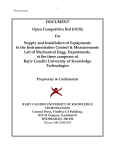
PCA design data represented in EDIF 4 0 0 Level 0 form is supported in the RASSP-MI. Figure 2.1.2-1 shows how the EDIF 4
0 0 Level 0 Interface fits into the RASSP-MI architecturally as well as the interface's internal architecture and data flow. The
EDIF 4 0 0 file format is first converted into its EDIF 4 0 0 Information Model equivalent. The Information Model is represented in
the EXPRESS[ISO94] data modeling language, making it possible to apply the EXPRESS Driven Data Conversion technique.
This technique was used in the development of the EDIF 4 0 0 to STEP AP210 Semantic Conversion Module . Currently, only
the subset of EDIF 4 0 0 Level 0 necessary to generate GenCAD data files (discussed in Section 2.2) is supported by the
RASSP-MI. It is expected that the coverage of the data converter will be expanded in the future. Areas of coverage that would be
useful to add include functional (gate-level) and pin swapping information.
Figure 2.1.2 - 1: EDIF 4 0 0 Level 0 Support in the RASSP Manufacturing Interface
The syntax of the data converter is as follows:
edif400l0_to_ap210 [-d -q -v] <input_file_name> [<output_file_name>]
Executing the command with no arguments causes a description of available options to be printed. If an output file name is not
provided, the automatically generated file name will have the following structure: <input_file_name>.step.
Since there will always be a single input file, the user interface of this data converter is significantly simpler than the one that
provides support for Mentor Board Station.
2.2 Output Interfaces
Once an electronic design has been completed and released to a manufacturing facility for production, a significant amount of
information remains to be generated based upon the design to be manufactured. For example, Numeric Control (NC) programs
must be generated to guide the operation of automatic component placement equipment. Many other types of manufacturing
machines on the production line also require NC programs or parameter files to guide their operation. In addition, automatic testing
equipment requires detailed knowledge of the design in order to operate correctly.
The RASSP Manufacturing Interface currently provides support for Mitron's CIMBridge, a system which provides the kind of
manufacturing support described above. Design information is entered into the CIMBridge system via a file format called
GenCAD . The RASSP-MI supports this system by synthesizing GenCAD file from PCA design data represented in STEP
AP210 form. This is shown in Figure 2.2-1
Figure 2.2- 1: Support for Mitron's CIMBridge in the RASSP Manufacturing Interface
The GenCAD conversion module is available in the RASSP-MI environment as the a2g executable. The syntax for this module is
as follows:
a2g [-d -q -v -vv] [-sr <STEP AP210 File Name>] [-gf <GenCAD File Name>]
A description of the options and defaults of a2g is printed if the program is executed with no arguments.
2.3 Manufacturing Resource Editor (MRE)
The Manufacturing Resource Editor (MRE) facilitates the capture of detailed manufacturing process information. Once captured,
this manufacturing capability data may be used by other components of the RASSP Manufacturing Interface. Specifically, the
MRE facilitates the capture of information regarding the following manufacturing elements:
Companies
Factories
Production Lines
Work Centers
PCA Manufacturing Machines
Manufacturing Engineers and Technicians
Environmental Facilities
This Section discusses the relationships between each of the above items. Also, the information captured for each item is
explained.
This rest of this section is organized as follows. Section 2.3.1 discusses operational aspects of the MRE. Section 2.3.2 provides
the user with factory configuration guidelines. Advice is provided to assist the user in making effective and efficient use of the
MRE. More detail concerning the operation of the MRE can be found in the Build I Manufacturing Interface User's
Manual[SCRA95].
2.3.1 MRE Operational Overview
This Section discusses operational basics of the MRE. Each of the nine Main Menu items offered by the MRE are discussed.
Several menu items activate separate data entry windows. Data entry fields within these windows may be editable or static (i.e.
informational only). Editable fields are labeled with red text, while static fields are labeled with blue text. Multiple data entry
screens may be active simultaneously; it is not necessary to close most data entry screens before opening another. When an editable
field is modified in one data entry screen while other screens are active that display the same field, the displayed fields are
dynamically updated.
Major Operations (main menu bar selections)
Figure 2.3.1-1 provides a hierarchical breakdown of the menu items available from the MRE's main menu. Figure 2.3.1-2 shows
the nine top-level MRE menu selections as they appear to the user. The capabilities and functions invoked by these menu items are
discussed in this Section.
Figure 2.3.1- 1: MRE Menu Options Tree
Figure 2.3.1- 2: Main MRE Window
File
The File menu items provide access to the following capabilities:
Load Data
Causes the MRE to read factory data from the file f_data.ob. This binary data file contains objects in the native format of the
underlying object-oriented framework upon which the MRE is built. This underlying framework is ProKappa, a knowledge-base
product offered by Intellicorp, Inc.
Unload Data
Removes the current data set from the MRE. This command only affects objects in memory. Version 2.5.9 of the MRE has a
known problem related to this command. If the user selects this command, and then attempts to Read STEP (described below) the
MRE will abort. In general, use of the Unload Data command is not recommended.
Save Data
Stores MRE data to the file "f_data.ob".
Save STEP
Stores MRE data to the file "f_data.step". This file conforms to the proposed STEP AP220 factory schema definition.
Read STEP
Loads AP220 formatted data from "f_data.step"
Exit
Terminates the current MRE session
Companies
The Companies menu is used to define companies and virtual corporations. The entities created with these menu items are
displayed in the Companies list box in the top-level MRE window. Companies are composed of factories. Factories and their
underlying substructure can be transferred from one company to another. Joint ownership of factories is not supported.
Create
Creates a new company. A dialog box appears allowing entry of company address, multiple phone numbers, and annual overhead
cost information.
Edit
Allows the user to add or change the address, phone numbers, and annual overhead cost information of the selected company.
Delete
Allows the user to remove the selected company from the database. This will not be allowed if the company owns factories. A
company's assets must be deleted or reassigned before a company can be removed.
Factories
The Factory menu is used to create and modify PCA manufacturing facilities. Assets such as production machines, employees and
environmental facilities may be assigned to a factory. Assigning an asset to a factory implies that it physically resides at the factory
location and implies that the factory "owns" the asset. Factory-owned assets may be further grouped into work centers and
production lines. Assets are initially classified as available . When an asset is assigned to a work center or production line, it is
reclassified as assigned .
Create
Creates a new factory and assigns it to the currently selected company. A dialog box appears allowing entry of factory address,
multiple phone numbers, and annual overhead cost information.
Edit
Allows the user to add or change the address, phone numbers, and annual overhead cost information of the selected factory.
Delete
Removes the selected factory from the database. This will not be allowed if the selected factory has production lines. Factory
assets must be deleted or reassigned before a factory can be removed.
Technology
Allows the user to enter the PCA technology characteristics and type supported by the factory.
Acquire
Allows the user to assign a factory to the currently selected company.
Production Lines
Production lines are composed of two components:
Work Centers
Good Practice "instance" values
Good practice values must be provided by the user. These parameters provide the recommended operating "boundary conditions"
for the production line. Operating outside of these boundaries may be possible, but will result in significantly reduced production
line effectiveness and is not recommended. These boundaries apply to features of PCA designs that may be processed by the
production line. An example of a Good Practice PCA layout constraint is minimum DIP to DIP spacing. Work Centers are clusters
of production machines and employees that perform a major PCA manufacturing task. An example of a task that a Work Center
would perform is surface mount component placement. Thus, Work Centers provide a detailed view of the machines and
employees that compose a production line, while the Good Practice values summarize the overall capabilities of the production
line.
Create
Creates a new production line and assigns it to the currently selected factory. The new production line inherits the Good practice
"global" values defined for the MRE session. These inherited values may be modified by editing the Good Practice "instance"
values of the production line. The new production line's good practice values may be modified by selecting Production Lines
Practice
Instance Values from the main menu.
Clone
Creates an exact copy of the currently selected production line. The user is promoted for the new production line's name. This
capability is useful for creating new production lines that are similar to an existing production line quickly.
Edit
Allows the user to add or change attributes of the selected production line.
Delete
Removes the selected production line from memory. All of the deleted production line's work centers are also deleted. All of the
deleted work center's employees and machines are re-classified from assigned to available .
Good Practice
Allows the user to edit the "global" or "instance" Good Practice values. The "global" values apply to the entire MRE session.
When a new production line is created, the "instance" values that apply to that production line are inherited from the "global"
values. The "instance" values apply only to the selected production line. The following Good Practice value types are supported:
Component spacing
Test point size and location
Height and Miscellaneous
Miscellaneous items include component orientation rules, whether fiducials are required or not, clearance required for
hand-inserted components, and component-to-PCB-edge clearance. Switching between the three panels of Good Practice editing
screen is done by selecting one of the above items from the Good Practice menu bar. Good Practice values must be entered by
the user. They are based on the experience of manufacturing engineers familiar with equipment present in the production line. This
feature of the Good Practice values distinguishes them from the values present in the Producibility Summary, which are generated
by the MRE from PCA manufacturing machine attributes.
Producibility Summary
The Producibility Summary is generated by the MRE and is based on the generic machine function definitions that apply to the
selected production line. The generic machines that are relevant to the selected production line are those generic machines that
define the capabilities of the production machines that make up the Work Centers that compose the production line. Addition,
deletion, or modification of one or more of a production line's production machines invalidates the associated Producibility
Summary. This is indicated by changing the Producibility Summary's status flag from valid to invalid . Regeneration of the
Producibility Summary will update its contents and set the status flag to valid . This is accomplished by selecting Production
Lines
Producibility Summary
Generate from the main menu. The Producibility Summary includes the
following information:
Applicable Generic Machines
Applicable Machine Functions
Process Limitations
Production Line Costs
The Producibility Summary status is shown in the upper-right corner of the producibility summary screen. The status may also be
viewed by selecting Production Lines
Producibility Summary
Report Status.
Work Centers
A Work center is a cluster of Employees and Production Machines that perform a specific PCA manufacturing task.
Create
Creates a new Work Center and assigns it to the currently selected Factory and Production Line. Work Centers are owned by a
factory and may be used by one or more Production Lines within the owning factory. The user may enter a name for the new work
center, or may choose a name from the provided pick list.
Edit
Allows the user to modify Work Center attributes.
Delete
Removes the selected Work Center from memory, unless the Work Center is assigned to multiple Production Lines. In this case,
only the reference to the Work Center within the context of the currently selected Production Line is deleted. When a Work Center
that is assigned to only one Production line is deleted, its assigned employees and machines are re-classified as available .
Assign
Allows the user to add an existing Work Center owned by the selected factory to the presently selected Production Line. The
Assign data entry window shows a list of Work Centers that are not currently assigned to the selected production line. When the
user selects one of these Work Centers, the "Machinery" and "Operators" list panels at the bottom of the window show the
Production Machines and their assigned operators.
Machinery
Management of PCA manufacturing machines is discussed in this section. Machine definitions are called "Generic" machines in the
MRE. Instances of Generic Machines are called Production Machines. Conceptually, a Generic Machine is a specific make and
model of PCA manufacturing machine. A Generic Machine includes all of the information necessary to define the machine's
capabilities and limits. A Production Machine is an occurrence of a Generic Machine owned by a Factory and possibly assigned to
a Work Center. Production Machines assigned to a Work Center have a status of assigned . Production Machines that are not
assigned to a Work Center have a status of available . A Production Machine may have an Employee assigned to it as a custodian.
Once assigned to a Work Center, a Production Machine may be assigned operators. MRE functions that operate on Generic and
Production Machines are discussed below.
Generic Machinery
Activates the Generic Machine Configurator window, which allows the user to create, edit and copy generic machines.
Production Machinery
View/Edit
Provides a list of all Production Machines owned by the selected Factory. Selecting a Production Machine from the list causes the
following information to be displayed:
Generic Machine
Assigned Work Center
Production Machine Information fields
Custodian
The Generic Machine and assigned Work Center information may not be modified. The Production Machine information fields and
Custodian are modifiable.
Production Machinery
Assign Machines
Provides a list of available Production Machines for the user to choose from. When a Production Machine is selected, descriptive
information is displayed. If the user selects the OK button, the selected Production Machine is assigned to the currently selected
Work Center. The name of the Work Center being assigned to is displayed in the top of this window. Multiple Production
Machines may be assigned by repeatedly selecting Production Machines followed by selecting the OK button. Selecting the
CLOSE button terminates the window.
Production Machinery
Release Machines
Removes the selected Production Machine from the Work Center to which it is currently assigned. The machine's status is changed
from assigned to available .
Production Machinery
Retire Machines
Provides a list of Production Machines owned by the selected Factory. A Production Machine may be retired by selecting it from
the list followed by selecting OK. Retired machines are not preserved by the MRE. Retiring a machine is equivalent to deleting it.
Before a Production Machine can be retired, it must have been Released. Multiple machines can be retired by repeatedly selecting
Production Machines followed by selecting OK. Selecting the CLOSE button terminates the window.
2.3.1.1.7 Human Resources
PCA manufacturing technicians and engineers are called "Employees" in the MRE. Employees, like Production Machines, are
owned by Factories. Employees may be assigned to Work Centers as operators and to Generic Machines as custodians. An
Employee's status is set to assigned when the Employee is assigned to a Work Center or a Generic Machine. Unassigned
Employees have a status of available .
View/Edit
Provides a list of defined Employees. Selecting an Employee causes the following information to be displayed:
Definitional information
Assignments
Certifications
Definitional information includes the Employees full name, "clock" number, labor grade, and hourly rate. Assignments to Work
Centers and Generic Machines are also displayed. Finally, skill Certifications and their expiration dates are shown. Definitional
information and Certifications are modifiable; Assignments are not.
Hire Employee
Allows the user to create a new Employee. A window appears and requests the new Employee's name. After entering the name
and selecting OK, a different window appears requesting Employee information. Once the requested information has been entered,
selecting OK completes the hiring process. The new employee are assigned to the selected factory with a status of available .
Terminate Employees
Provides a list of Employees owned by the selected Factory. An Employee is deleted by selecting that Employee from the list and
selecting the OK button. All of the Employee's assignments must have been Released or the delete request will be denied.
Assign Employees
Provides a list of available Employees owned by the selected Factory. An Employee is assigned to the selected Work Center by
selecting the Employee followed by selecting the OK button. Multiple Employees may be assigned by repeatedly selecting
Employees followed by selecting the OK button. Selecting the CLOSE button terminates the window.
Release Employees
Releases selected employees from their current assignments and changes their status to available . Assignments from which
employees may be released include assignments to Work Centers and Production Machines.
Certifications
Provides a list of defined skill Certifications. Certifications required by a manufacturing facility may be assigned to the selected
Factory by selecting the Certification followed by selecting ADD. A list of Certifications relevant to the selected Factory is shown
in the bottom panel of the Certifications window. Employees owned by the selected Factory may have one or more of these
Certifications assigned to them. This is accomplished by selecting the Human Resources
View/Edit option, selecting
an Employee, selecting a Certification, and finally selecting ADD. Note the Query menu option of the Certifications data entry
screen performs no function in version 2.5.9 of the MRE.
Environmental Facilities
Management of environmental facilities (such as clean rooms) is discussed in this section. Selecting Environmental Facilities
View/Edit from the main menu activates the environmental facility Workbench. The Workbench supports the following
functions:
Facility Add/Create
Creates a new environmental facility and assigns it to the selected factory.
Facility Delete
Removes the selected Environmental Facility from the selected Factory. Work Centers assigned to the Environmental Facility are
not deleted.
Characteristics
Allows the user to add, delete, and modify attributes associated with the selected Environmental Facility.
Variability
Allows the user to add, delete, and modify the statistical properties of a Characteristic associated with the selected Environmental
Facility.
Add/Remove Work Centers
Allows the user to add or remove Work Centers from the selected Environmental Facility.
UtilitiesThe following items are available from the Utilities menu:
Reset Frames
Remove Corrupted Objects
Label to Name
Name to Label
Convert f_data File
Set Options
About MRE
Reset Frames
Flushes the MRE's window panel cache. The first time a data entry or other type of window is displayed by the MRE, data objects
are created to support the widgets and panels that compose the window. When the window is closed, these data objects are not
deleted. Therefore, when the same window is requested again, it is displayed more quickly. However, if memory consumption
becomes an issue, Reset Frames may be used to clear these data objects from memory. Otherwise, this utility should not be used
as it will degrade performance.
Remove Corrupted Objects
Finds and deleted data objects that have been damaged. This utility may be needed if the f_data.ob file becomes damaged.
Label to Name
Populates the name attribute of all data objects with the type-name of the data object itself. This exists for debugging purposes
only and should not be used by the MRE user.
Name to Label
Modifies the type-name of all data objects to be the same as the contents of their name attributes. This exists for debugging
purposes only and should not be used by the MRE user.
Convert f_data File
Update and read an f_data.ob file from an older version of the MRE.
Set Options
Allows the user to alter a variety of global options. The user may perform the following tasks:
Add and Delete Generic Machine types
Add and Delete Work Center types
Add and Delete Environmental Facility types
Modify naming conventions
Selecting the Set Options menu item activates a workbench that facilitates selection of available options. Once saved, these
options apply for the current and subsequent MRE sessions.
About MRE
Lists the current version of the MRE and provides a brief description.
2.3.2 Data Population Constraints
Constraints exist on the order in which objects may be created in the MRE. This section summarizes these constraints to help the
user more efficiently capture manufacturing capabilities information using the MRE.The first objects created in the MRE must be
items that can exist independently. These include Companies and global Good Practice values. Once a Company exists, Factories
may be created. The Factory is the owner of most other items managed by the MRE, any of which may be created once a Factory
exists. These items are listed below:
Production Lines
Generic Machines
Production Machines
Employees
Certifications
Environmental Facilities
Once a Production Line exists, Work Centers may be created. A Work Center may then have Production Machines and Employees
assigned to it.
2.3.3 Variable and Fixed Cost Computations
The fixed and variable costs for the selected production line are computed and displayed in the Producibility Summary screen,
which is activated by selecting the main menu option Production Lines
Producibility Summary
Generate.
These approximated costs are derived from five cost data specifications entered into the MRE. Fixed costs of a production line are
computed according to the following formula:
Figure 2 - ?: XXXX
Variable costs of a production line are computed as the sum of these three components:
Production Line hourly support rate
Hourly rate of Production Machines assigned to Production Line
Hourly rate of Employees assigned to Production LineTable 2.3.3-1 indicates how to navigate to each of the five cost data
items managed by the MRE. Figure 2.3.3-1 provides a summary of how each component of a manufacturing facility's
costs are accounted for within the MRE.
Table 2.3.3-1 -- Navigation Paths to MRE Cost Data
Cost Type
Fixed Costs
($)
Variable Costs
($/Hour)
Cost Item
Menu Path
Company Overhead
Companies
Factory Overhead
Factories
Production Line Support
Production Line
Machine Operation
Machinery
Human Resources
Human Resources
Edit
Edit
Edit
Production Machinery
View/Edit
View/Edit
Figure 2.3.3- 1: Production Cost Derivation Summary
2.4 Producibility Analysis
The Producibility Analyzer (PA) used within the RASSP-MI is a commercialized version of the Producibility Advisor . The
Producibility Advisor was developed as part of a previous, government funded effort and significantly enhanced as part of the
RASSP Manufacturing Interface effort. The Producibility Analyzer is commercially available from Mitron Corporation.
The PA evaluates PCA product data within the context of specific PCA manufacturing constraints. The use of specific PCA design
and production line characteristics enables a more precise analysis than may be obtained using generic producibility guidelines
exclusively. The PA uses product data in GenCAD format, as do all of Mitron's commercially available products. Within the
context of the RASSP-MI, the source of the GenCAD data is STEP AP210 (as discussed in Section 2.2)
The capabilities of the manufacturing facility are captured by the PA and stored as parameters to a set of rules developed
specifically for the hosting facility. Using this information, the PA evaluates producibility with respect to specific production lines
and generates producibility reports.
Please refer to Mitron's documentation for a full discussion of the operational details and capabilities of the Producibility
Analyzer .
2.5 Rule Definition/Execution Facility (RD/EF)
To pose and act on multi-domain questions, facilities were developed to define and execute Design For X (DFx) rules. A Rules
Definition Facility (RDF) was developed to define generic DFx rules. A Rules Execution Facility (REF) was developed to execute
the defined rules against STEP Application Protocol data.
2.5.1 Rules Definition Facility
The Rules Definition Facility (RDF) is a database editor designed to assist engineers in capturing PCA related design and
manufacturing process knowledge in the form of rules. The rules are stored in an object oriented database for future use in an
integrated knowledge based framework or system.
Using the Rules Definition Facility, rules can be created, edited and/or removed. Rule meta information (concerning rule approval,
origination, description, justification, etc.) can be defined. Rule execution code, premise and conclusion components, can be
created and edited using context sensitive menus. The rule premise component, or "IF" statement conditions, define what actions
are required before the rule conclusion component is executed. The rule premise consists of logical combinations (ANDing or
ORing) of system functions. System functions include: storing temporal information to the database (facts), storing permanent
information to the database (object attributes) and providing feedback to the user in the form of messages and issues. The
conclusion component consists of actions to take as a result of all of the premise conditions being met. The rule conclusion is a
logical combination (ANDing) of system functions. The Bachus-Naur Form (BNF) grammar description provided in Figure
2.5.1-1 defines the rule definition format.
Note that a rule conclusion can include the storing of facts and/or object attributes (system functions). A rule premise may include
functions that test facts and/or object attributes. Utilizing the two preceding capabilities allows one rule to call another rule. This
process is known as 'chaining'. This ability can be used to capture the intent of a multistage rule with several smaller rules.
Additionally, it allows the system to continually ask new questions when the answers from other questions support information
needed by the new questions.
<rule> ::= <premise> <conclusion>
<premise> ::= <complex clause> { Or <complex clause> }*
<complex clause> ::= <simple clause> { And <simple clause> }*
<simple clause> ::= <system function> <function parameter>*
<conclusion> ::= <simple clause> { And <simple clause> }*
<function parameter> ::= <simple clause> | <constant> | <variable><variable> Alphanumeric pattern instantiated as object when rule is fired (e.g. component1, layer2,
net3).
<constant> - Number, Integer or Floating Point
<system function> - Any system provided function that returns a value for
testing or comparison (e.g. logical, math)
Note: This Backus-Naur Form has been extended using the Kleene cross (sequence of one or more) and the
Kleene Star (sequence of zero or more).
Figure 2.5.1-1 -- Backus-Naur Form for Rules
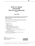
Information defined in the Rules Definition Facility can be stored in the database and later executed using the Rules Execution
Facility (REF).
The Rules Definition Facility organizes rules by status and set. Rule status defines the progress of a rule in the process of defining,
submitting and accepting rules. Rule sets are user defined categories that aid in organizing rules into small, meaningful groups. In
the RDF, rules are selected either by their current status or by the rule set that they belong to.
When rules are first created their status is initialized to proposed. A proposed rule contains only meta-data about the rule (its
description, justification, etc.). Note the Rules Definition Facility allows the user to input rule detail via the Rule Edit Panel on a
proposed rule. Proposed rules are the only rules that can be deleted.
A proposed rule can either be accepted or rejected. If the rule is rejected, rejection information is requested, its status is changed
to rejected and the rule can no longer be edited. If the rule is accepted, its status is changed to inwork and the rule can be edited.
Inwork rules are typically used in conjunction with the Rules Execution Facility in an edit/execute/ cycle. Once editing is
completed on an inwork rule, it can be submitted for approval or disapproval. The status of the inwork rule is changed to
submitted while the approval process is taking place. If the submitted rule is disapproved, disapproval information is
requested, its status is changed to disapproved and the rule can no longer be edited. If the submitted rule is approved, its status
is changed to approved. If an approved rule has defined a rule that it supersedes, then that rule will have its status changed to
superseded. Any rule can be demoted to proposed by using the demote rule menu selection. Figure 2.5.1-2 depicts the state
diagram that shows how the state of a rule may change over time.
Figure 2.5.1- 2: Rule Status Process Flow
To simplify the task of defining and executing rules, the Rules Definition Facility provides for the organization of rules into rule
sets. A rule set is a group of rules that share a common subject. Rule sets are arranged in a rule hierarchy. The rule sets and their
hierarchy are defined by the user. As an example, a user may wish to define a set of design rules. Subsets of rules under the
design set could be analog, digital and mixed.
A rule can belong to any number of rule sets. When rules are executed in the Rules Execution Facility they must first be selected
via rule set. Figure 2.5.1-3 depicts an example of a rule set hierarchy and its associated rule sets.
2.5.2 Rules Execution Facility
The goal of rules execution is to discover and report issues that exist concerning a product. The Rules Execution Facility is used to
execute PCA related rules as defined by the Rules Definition Facility. Product data for a specific PCA (AP210) is created by
executing the appropriate data converter. Manufacturing data is loaded from the manufacturing database created by the
Manufacturing Resource Editor.
Figure 2.5.1- 3: Example Rule Sets and Hierarchy
Other data, available in STEP format, can be loaded at the users option. Rule results are displayed in the form of messages, dialog
boxes, rule result files and rule issues. The REF allows the execution of both Approved and Inwork rules. Rules defined in rule
sets can be selected and added to the rule agenda. Individual rules, rule sets, or all rules can be executed.
System Operation
The Rules Execution Facility Main Panel provides functionality to select rules sets and their associated rules for placement on the
rule agenda. Rules on the rule agenda can be executed as required. Figure 2.5.2-1 shows the layout of the REF's user interface.
Figure 2.5.2- 1: REF Main Panel Window Locations
Selecting Rules by Status
The Rule Sets window (located on the left of the REF Main Panel) displays the defined sets for the currently selected rule status.
Rule status is selected at the bottom of the Rule Sets window. The Rule Execution Facility supports the execution of Inwork and
Approved rules (as defined by the Rules Definition Facility).
Selecting Approved Rules
Selecting the Approved Rule Status check box updates the Rules by Set listing with Approved rule sets and their associated
number of rules. All inwork rules are removed from the Rule Agenda. Previously selected approved rules will be added to the Rule
Agenda.
Selecting Inwork Rules
Selecting the Inwork Rule Status check box updates the Rules by Set listing with Inwork rule sets and their associated number of
rules. All approved rules are removed from the Rule Agenda. Previously selected inwork rules will be added to the Rule Agenda.
Selecting Rules by Set
The Rule Sets window (located on the left of the REF Main Panel) displays the defined sets for the currently selected rule status.
Left clicking on a rule set will toggle that particular set (either selecting or deselecting) and add/remove its rules to/from the Rule
Agenda. Using the Rule Sets Reset checkbox, all rule sets can be deselected (using the NONE selection) or all rule sets can be
selected (using the ALL selection).
Working with the Rule Agenda
Only rules defined on the Rule Agenda can be executed. Selecting rules sets place the rules defined to that set on the Rule Agenda.
Individual or groups of rules can be removed from the Rule Agenda. All rules, individual rules, or groups of rules on the Rule
Agenda can be executed.
Resetting Rules in the Rule Agenda
As rules sets are selected, their associated rules are added to the Rule Agenda. Individual rules can be removed. The Reset
Agenda button is used to reset the Rule Agenda to display all of the rules associated with the selected rule sets, as well as remove
any rule execution information associated with these rules.
Adding Rules to the Rule Agenda
As rules sets are selected, their associated rules are added to the Rule Agenda. Selecting and deselecting rule sets adds and removes
their rules to and from the Rule Agenda.
Removing Rules from the Rule Agenda
As rules sets are selected, their associated rules are added to the Rule Agenda. Selecting and deselecting rule sets adds and removes
their rules to/from the Rule Agenda. The Remove Selected Rules button is used to remove individual rules from the Rule
Agenda. Rules to be removed must first be selected in the Rule Agenda window.
Updating the Rule Execution Data on the Rule Agenda
Each time a rule is executed a record of execution attempts and successes is stored. The Update Rule Execution Data button
displays the execution record for the rules on the Rule Agenda.
Resetting the Rule Execution Data on the Rule Agenda
Each time a rule is executed a record of execution attempts and successes is stored. The Reset Rule Results when Rules are
Execution button will clear any rule execution results whenever a rule is initiated.
Executing Rules
Rules on the Rule Agenda (either all of the rules or a selected subset) can be executed. The Run Selected Rules button is used
to execute only those rules in the Rule Agenda that are selected. The Run All Rules button is used to execute all the rules in the
Rule Agenda.
Rule Execution Information
As rules are executed the Rules Execution Facility provides summary information concerning the number of rules that are
attempted and the number of rules that succeed. Table 2.5.2-1 describes the available summary information.
Table 2.5.2-1 -- Rule Execution Information
Rule Summary Type
Individual Rules Attempted
Individual Rules Succeeded
Total Rules Attempted
Total Rules Succeeded
Description
Number of different rules that are attempted
Number of different rules that succeed
Total number of rules (some rules are counted more than once) that are
attempted
Total number of rules (some rules are counted more than once) that succeed
Debugging Rules
To aid in debugging the execution of rules, the Rules Execution Facility supports the reporting of attempted rules and succeeded
rules.
Reporting Attempted Rules
The Report Attempted Rules button is used to report the name of each rule as it is attempted. The rules object and name are
displayed in the Message Panel and printed to the REF log file. Note that if many rules are attempted, this reporting will slow
down execution considerably.
Reporting Succeeded Rules
The Report Succeeded Rules button is used to report the name of each rule if it succeeds. The rules object and name is
displayed in the Message Panel and printed to the REF log file. Note that if many rules succeed, this reporting will slow down
execution considerably.
Stopping Rules
Once rule execution is initiated it will continue until all selected rules are executed. The Stop Rules button will stop the execution
mechanism from starting any new rules. The currently executing rule will run to completion. There is presently no elegant way of
halting the currently executing rule.
Displaying Rule Facts
Rules can write facts for temporary use by other rules or for storing temporary knowledge (e.g. number of components, maximum
component height, etc.). The facts are written in response to rule premises or conclusions that include the function PutFact or
PutFacts. The Display Facts button allows the display of all presently defined facts. When selected a dialog list box is
provided that lists each fact, attribute and value triplet. If no facts are presently defined, a message stating so will be displayed.
Note that when rules are executed (either by the Run Selected Rules button or the Run All Rules button), existing facts will
not be deleted.
Clearing Rule Facts
Rules can write facts for temporary use by other rules or for storing temporary knowledge (e.g. number of components, maximum
component height, etc.). The facts are written in response to rule premises or conclusions that include the function PutFact or
PutFacts. The Clear Facts button allows the removal of all accumulated facts and their attributes.
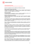
2.6 Web-based interface
The web-based interface to the RASSP Manufacturing Interface enables users of the system to access the capabilities of the
RASSP-MI remotely. The implementation is currently limited to providing remote access to the Producibility Analyzer, but can be
extended to include other subsystems of the RASSP-MI in the future. Figure 2.6-1 shows the architecture of the web-based
interface.
Figure 2.6- 1: Architecture of the Web-based Interface
An integral component of the interface is the Citrix Winframe server software, which extends the capabilities of Windows NT. The
Citrix Winframe technology acts as a redirectable layer between Windows NT applications and the Windows NT rendering layer.
On the server machine, an application's display calls are intercepted by Winframe and redirected to a remote client machine. A
Citrix compliant plug-in must be running on the client machine to interpret the incoming data stream and generate the application
GUI. The plug-in for Windows 95 and Windows NT is freely available at http://www.citrix.com . The plug-in for UNIX is
available for a nominal fee. The Winframe server is built into the operating system; a special version of Windows NT modified by
Citrix must be purchased for the server machine.
Once the Citrix client plug-in is installed, the Producibility Analyzer can be accessed from a site hosting the RASSP Manufacturing
Interface. The RASSP-MI can be installed such that its capabilities can be accessed via the Internet, or only through the corporate
intranet.
For more details on the technology underlying the web-based interface and a discussion of alternate approaches to providing
remote access to RASSP-MI capabilities, see [SCRA97].
Next: 3 RASSP Manufacturing Interface Usage Scenarios Up: Appnotes Index Previous: 1 Introduction
Approved for Public Release; Distribution Unlimited Dennis Basara
Next: 4 LMC Installation Up: Appnotes Index Previous:2 Technology Description
RASSP Manufacturing Interface
(RASSP-MI) Appnote
3.0 RASSP Manufacturing Interface Usage Scenarios
This Section discusses three major activities supported by the RASSP Manufacturing Interface. These
activities are described below:
Manufacturing facility-specific producibility analysis early in the design cycle
Capturing manufacturing facility knowledge in an executable form
Automation of tedious, error-prone tasks
Each of these three activities are discussed in detail in the following Sections.
3.1 Remote, Facility Specific Producibility Analysis
A PCA designer will first use the Manufacturing Interface once initial PCA component placement has been
completed. At this point, the design is converted into a standard representation, thus making it accessible to
the core functionality of the Manufacturing Interface. The Producibility Analyzer can then be used to analyze
the PCA design with respect to specific production capabilities. The output of this analysis will be
producibility issues. These issues may be resolved by either modifying the PCA design, by selecting different
production lines, or a combination of the two. If the PCA design is modified during the issue resolution
process, the design may again be converted to the standard form and analyzed with the Producibility Analyzer.
This process is repeated until no issues remain or it becomes clear that the manufacturing facility is not capable
of producing the product within an acceptable amount of time, at an acceptable cost, or with an acceptable
degree of quality.
3.2 Capturing Manufacturing Facility Knowledge
The manufacturing engineer uses the Manufacturing Interface for two distinct purposes:
Capturing manufacturing capabilities
Generating NC programs for PCA assembly machines
Manufacturing capabilities are captured using the Manufacturing Resource Editor (MRE). Capabilities thus
captured serve two purposes. First, they provide PCA manufacturing capability information to the Rule
Execution Facility. Second, they provide browsable electronic documentation of the manufacturing facility's
equipment and organization. Knowledge regarding specific PCA manufacturing equipment may be captured
using the MRE, making it more widely available and ensuring that such knowledge will not be lost due to
personnel changes.
3.3 Automation Enabled by Industry Standards
Manufacturing engineers may also use the Manufacturing Interface to generate NC programs and setup sheets
for PCA assembly machines. The RASSP-MI enables this kind of automation by providing PCA product data
in the GenCAD data format. GenCAD is used by Mitron's CIMBridge suite of manufacturing support tools,
which include NC program generators and process planning capabilities. In addition, GenCAD forms the
basis of the IPC-2510[IPC97] standard currently in development. Once this standard has been completed, the
current GenCAD capability can be updated to comply with IPC-2510, thus increasing the generality of the
RASSP-MI's capabilities.
Next: 4 LMC Installation Up: Appnotes Index Previous:2 Technology Description
Approved for Public Release; Distribution Unlimited Dennis Basara
Next: 5 Summary Up: Appnotes Index Previous:3 RASSP Manufacturing Interface Usage Scenarios
RASSP Manufacturing Interface
(RASSP-MI) Appnote
4.0 LMC Installation
The RASSP-MI has been integrated into the RASSP enterprise system and is being utilized by an LMC
manufacturing facility. Over 100 PCA designs have been processed by the RASSP-MI at this facility. Results
indicate a significant reduction in manufacturing errors and time required to go from design to manufacturing
setup since the RASSP-MI was integrated into the process.
4.1 Process Improvements
Because this facility had traditionally not been part of the product design process, manufacturability issues
were often present in data received from the design organization. These issues had to be resolved before
production could begin. Resolution might require a re-design effort by the team originating the design.
Because the cost of design modification late in the design cycle is high, manufacturability issues that were not
insurmountable were often allowed to remain, even though they increased recurring manufacturing costs.
These problems not only contributed to difficulty in achieving first-pass manufacturing success, but
unnecessarily increased production difficulties and the cost of each PCA produced. The RASSP-MI corrected
this by enabling virtual partnering between design and manufacturing organizations.
Prior to use of the RASSP Manufacturing Interface, inaccurate placement of surface-mount components
caused significant recurring production difficulty. The manual data exchange process employed did not assure
accuracy of placement information to within 1/1000th of an inch. Without this level of accuracy, it was
common for small discrete surface-mount components to move during the solder reflow process, a difficulty
referred to as component drift . For some components, this movement caused them to make poor or no
contact with their designated connection points on the PCB. Attempts to counter this effect centered around
modifying "offset" values in the automatic surface-mount placement equipment. Failures observed during the
manufacture of a batch of PCAs would be analyzed by a manufacturing engineer, who would then use the
analysis results to modify placement equipment "offset" values in an attempt to correct the component
misplacement problem. This approach improved yields, but was never able to eliminate PCA failures, even
over several years of production of the same design.
Despite the ingenuity and tenacity of the engineers and technicians supporting the facility, the inaccurate data
utilized for production exacted a heavy toll. For one program examined, 100% of 80,000 manufactured PCAs
had defects caused by inaccurate placement of surface-mount components. These defects required manual
repair. To make matters worse, on average approximately 30% of components per PCA would require repair.
Remarkably, it was determined that the cost required to overcome these difficulties, given the over-the-wall
product data exchange paradigm the facility was obligated to operate within, exceeded the cost of performing
the repairs.
The PCA designs processed thus far using the RASSP-MI are comparable in complexity to the design
previously discussed. The metrics collected regarding the success of these designs has been impressive. The
amount of rework required has been reduced by at least 80%, and the amount of time required to perform
manufacturing setup once the design data has been delivered has been reduced by a factor of 10[Gad97].
4.2 Payback Analysis
Equation 1 below defines Ct to be the cost associated with the time required to correct surface-mount
component placement errors introduced by the manual data conversion process previously employed by the
manufacturing facility.
Equation 1: Production Cost Associated with Pre-RASSP Process
Where:
MElr is the labor rate of a Manufacturing Engineer
Tm is the time spent modifying automatic placement "offset" values per day of production
Pr is the percent of PCAs requiring repair due to poor component placement
Tr is the average time spent repairing a PCA
Np is the total number of PCAs produced
MTlr is the labor rate of a Manufacturing Technician
Using the RASSP-MI, NC code for component placement machines is derived automatically from the original
CAD data representation of the design. Therefore, the placement information in the NC code is as accurate as
that present in the CAD system. Due to the increased quality of the placement data, it was determined that all
of the "offset" values that had been programmed into the surface-mount placement equipment at the
manufacturing facility could be reset to 0, which resulted in a simplification of the programming procedures
required for this equipment. The more accurate information has also resulted in a near 0% component
misplacement rate.
Therefore, using the RASSP-MI results, Ct-RASSP is negligible. Prior to use of the RASSP-MI,
Ct-Pre_RASSP was significantly higher. Equation 2 presents the production costs, Ct-Pre_RASSP , associated
with the program previously described in which a total of 80,000 PCAs were produced.
Equation 2 Reduction in Production Cost using RASSP Manufacturing Interface
Based upon nominal labor cost values, the above result indicates a cost of $20/PCA attributable to the absence
of an effective and efficient manufacturing interface capability. Given the production rate of the manufacturing
facility, the development costs of the RASSP-MI will be paid back after approximately 5 months of use. This
result highlights the tremendous savings enabled by the RASSP-MI.
These results highlight the value of virtual concurrent engineering and the importance of an agile
manufacturing interface and explain why the Lockheed Martin PCA manufacturing facility was identified for a
Best Practice award [Best95]. With further refinements, it is expected that first-pass manufacturing success of
PCAs will be consistently achieved, primarily due to the capabilities provided and enabled by the RASSP agile
manufacturing interface.
Next: 5 Summary Up: Appnotes Index Previous:3 RASSP Manufacturing Interface Usage Scenarios
Approved for Public Release; Distribution Unlimited Dennis Basara
Next: 6 Reference List Up: Appnotes Index Previous:4 LMC Installation
RASSP Manufacturing Interface
(RASSP-MI) Appnote
5.0 Summary
The goal of an agile manufacturing interface is to enable the formation of virtual organizations by providing
the information sharing infrastructure and robust DFx mechanisms those organizations need in order to
develop successful products. This Application Note presented the requirements for an agile manufacturing
interface and the results obtained using the agile manufacturing interface developed by the RASSP program
(the RASSP-MI) in a production environment. By reducing cost and time-to-market, the RASSP-MI is
contributing significantly towards the accomplishment of the RASSP program's goals of a 4x improvement in
cycle-time, quality and cost.
In conclusion, the RASSP Manufacturing Interface allows physically distributed design and manufacturing
teams to work collaboratively in a virtual organization to design manufacturability into complex products early
in the design process. It also helps to ensure that complex product designs are ready to be manufactured
before production begins, thereby supporting the goal of first-pass manufacturing success. For complex
products in general, implementations of this capability promise to produce significant reductions in product
development time and cost while improving product quality.
Next: 6 Reference List Up: Appnotes Index Previous:4 LMC Installation
Approved for Public Release; Distribution Unlimited Dennis Basara
Next: Up: Appnotes Index Previous:5 Summary
RASSP Manufacturing Interface
(RASSP-MI) Appnote
References
[Hin94] Hines, L.E., Gadient, A.J., "EXPRESS Driven Data Conversion", in Concurrent Engineering:
Research and Applications Conference Proceedings , Pittsburgh, PA, August, 1994, pp 313 - 322.
[SCRA95] SCRA, "Build I Manufacturing Interface User's Manual", MMC-RASSP 7.01.00, November 14,
1995.
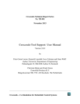
[SCRA97] SCRA, "RASSP Manufacturing Interface WWW Integration of Mitron's CIMBridge Product,
Final Report", MMC-RASSP 8.01.00, April 29, 1997.
[Best95] "Report of Survey Conducted at Lockheed Martin Electronics & Missiles, Orlando, FL", Best
Manufacturing Practices Center of Excellence, College Park, Maryland, April 1995.
[Gad97] A. J. Gadient, L. E. Hines, J. Welsh, A. P. Schwalb, "Agility through Information Sharing: Results
Achieved in a Production Setting", Concurrent Engineering: Research and Applications Journal , pp. 101 111, volume 5, number 2, June 1997.
[Lau96] Lau, R.Y.W., "EDIF: Electronic Design Interchange Format Version 4 0 0 Information Model",
Electronic Industries Association, EDIF Steering Committee, 1996.
[ISO96] ISO/DIS 10303-210:1996, "Industrial automation systems and integration Product data
representation and exchange Part 210 Printed circuit assembly product design data".
[ISO94] ISO 10303-11:1994, "Industrial automation systems and integration Product data representation and
exchange Part 11: Description methods: The EXPRESS language reference manual".
[IPC97] IPC-2510, "GenCAM: The Generic Computer Aided Manufacturing Series for Printed Boards and
Printed Board Assembly Manufacturing Descriptions", The Institute for Interconnecting and Packaging
Electronic Circuits, March 1997.
Next: Up: Appnotes Index Previous:5 Summary
Approved for Public Release; Distribution Unlimited Dennis Basara