1
User ’ s Manual
Model No.: C1190
U se r ’
Digital Wireless Surveillance Kit
PLEASE READ CAREFULLY AND SAVE
This manual contains important information about this product's operation.
If you are installing this product for others, you must leave this manual -or a
copy- with the end user.
Contents
What You Get
Safety Precaution and Hazard Notice / FCC Warning / Disposal
Knowing Devices Parts
Getting Start
Connecting to TV
Step1: Connecting Devices
Step2: Basic Operation
Step3: Advance Operation
Connecting to PC
About Digital Wireless Technology
Trouble Shooting
Product Specification
What You Get
(1) Digital Wireless Color Camera
(1) Wireless Receiver
(1) Wireless Camera Stand
(1) 5V AC/DC Adaptor for Camera
(1) 5V AC/DC Adaptor for Receiver
(2) Antenna for Camera and Receiver
(1) A/V Cable
(1) USB Cable
(1) Screw bag
(2) Manual
(1) Installation Software CD
1
Product Specification
RF Specification
RF Frequency
2400MHz~2483.5MHz
Modulation
GFSK
Spread Spectrum
Frequency Hopping
Anti Interference
Clean Channel Dynamic Select
Selectable Camera Channel
4
Data Rate
2Mbps
Channel Bandwidth
2MHz
Transmission Range
Important Safety Precautions
200 metres / 600 Feet in open space
Image Specification
Output Image Resolution
640 x 480 (VGA) / 320 x 240 (QVGA)
Image Processing
Motion JPEG
Exposure
Auto
White Balance
Auto
System Specification
Camera
Receiver
Operating voltage
5V 1A
5V 1A
Current Consumption
650mA max
300mA max
Low Light Sensitivity
1 ~ 8 Lux
Low Light solution
24 IR LEDs / 1 EDS
Picture Sensor
Micron MT9V011 1/4” Color
Lens
CMOS
F3.6mm
H: 53o
V: 40o
PC OUT: USB 1.1 or above
TV OUT : 3.5mm phonejack
Output Jack
Weight
Camera:240g
Receiver:120g
Dimension
Camera:164×64×42mm
Receiver:85×81×27mm
Operating Temperature
-10oC to +50oC
Operating Voltage
100~240V / 60 or 50 Hz
System Requirement
1GHz or faster processor
Microsoft® Windows® XP with Service Pack 2 or 3 or Windows Vista®
1GB of RAM recommend for Windows Vista
1.0GB of available hard-disk space for recording
Color monitor with 16-bit color video card
1,024x768 monitor resolution at 96dpi or less.
Microsoft DirectX 9 compatible display driver
CD-ROM drive
USB port 1.1 or above
17
WELCOME,
Dear user, thanks for purchasing this product.
Much investment in time and effort has gone into its development,
We now presenting you ZERO interference digital wireless security camera
and it is our hope that it will bring you many years of trouble-free peace-in-mind service.
Please read this user manual carefully before installing or using these units.
Digital Wireless Camera and Receiver kit with USB connectivity
Please read before installing and using this product
Damages caused by non-compliance with this operating manual will void the warranty! We will not assume any liability for
damages to items or persons caused by improper handling or non-compliance with the safety notices! Any warranty claim will
be null and void in such cases.
1. Do not drop, puncture or disassemble the camera or receiver; otherwise the warranty will be voided.
2. Avoid all contact with water, and dry hands before using.
3. Never tug on the power cords. Use the plug to unplug it from the wall outlet.
4. Do not expose the camera or receiver to high temperature or leave it in direct sunlight. Doing so may damage the camera
or cause camera temporary malfunction.
5. Use the devices with care. Avoid pressing hard on the camera or receiver body.
6. For your own safety, avoid using the camera or power off the camera when there is a storm or lightning.
7. Remove the power adapter during long periods between usages.
8. Use only the accessories and power adapters supplied by the manufacturer.
9. To meet the regulations pertaining to parental responsibility, keep the devices out of the reach of infants.
10. Check power cables, do not get crushed or damaged by sharp edges whenever the devices are in operation.
FCC Compliance Statement:
This device complies with Part 15 of the FCC Rules.
Operation is subjected to the following two conditions:
(1) this device may not cause harmful interference, and
(2) this device must accept any interference
received, including interference that may cause
undesired operation.
Products with CE Marking comply with EMC
Directive (2004/108/EC); Low Voltage Directive
(73/23/EEC); R&TTE(1999/5/EC) issued by the
Commission of the European Community. Compliance
with these directives implies conformity to the following
European Norms:
EMC: EN 301 489
LVD: EN 60950
Radio: EN 300 328
FCC/CE WARNING
This equipment has been tested and found to comply with limits for a Class B digital device, pursuant to Part 15 of the FCC rules
and ETSI (EN) 300 328. These limits are designed to provide reasonable protection against harmful interference in residential
installations. This equipment generates, uses, and can radiate radio frequency energy, and if not installed and used in accordance
with the instructions, may cause harmful interference to radio communications.
However, there is no guarantee that interference will not occur in a particular installation. If this equipment does cause interference
to radio or television equipment reception, which can be determined by turning the equipment off and on, the user is encouraged to
try to correct the interference by one or more of the following measures:
-Reorient or relocate the receiving antenna.
-Move the equipment away from the receiver.
-Plug the equipment into an outlet on a circuit different from that to which the receiver is connected.
-Consult the dealer or an experienced radio/television technician for additional suggestions.
You are cautioned that any change or modifications to the equipment not expressly approved by the party responsible for compliance
could void Your authority to operate such equipment.
Disposal
If the camera system no longer functions or can no longer be repaired, it must be disposed of according to the valid statutory
regulations. Disposal of spent batteries / accumulators:
You are required by law (Battery Ordinance) to return all spent batteries and accumulators. Disposing of spent
batteries/accumulators with common household waste is prohibited! Batteries/accumulators that contain
hazardous substances are marked with the symbols on the side. These symbols indicate that it is prohibited to
dispose of these batteries/ accumulators in the household waste.
The abbreviations for the respective heavy metals are: Cd= cadmium, Hg= mercury, Pb= lead. You can return
spent batteries and accumulators that can no longer be charged to the designated collection points in your
community, outlets or wherever batteries or accumulators are sold. Following these instructions will allow you
to fulfill the legal requirements and contribute to the protection of our environment!
2
Knowing Devices Parts
Trouble Shooting
Before requesting service, please make the below checks. If you are in doubt
about some of the check points, or if the remedies indicated in the chart do not
solve the problem, please contact us.
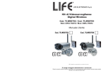
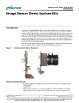
Camera
front side
1
11
10
2
back side
Problem
Possible Causes
Remedies
System Message
shows “NO Signal ”
No power supply to
corresponding camera(s)
First identify the channel number, find the
corresponding camera. If camera power status
indicator (RED LED) lights off, check power
adapter and power cable connection.
3
Channel is not paired
with camera yet
4
7
for detail. Once pairing completed and camera
3
8
9
12
13
12
6
1.Antenna
2. Sunshield
3. Camera Lens
4. T- bolt
5. Camera Stand
14
Service out of range
11. Link LED
12. U holder / U holder screw
13. Cam Pair
14. Power adaptor
6. Microphone
7. Power Jack
8. EDS
9. IR LED
10.Power LED
If possible, remove major obstacles in between
camera and receiver. Or relocate the camera to
proper location.
Camera antenna
Secure antenna to camera body tightly.
connection loss
Low signal or unstable
Antenna directional
signal
limitation
If possible, remove major obstacles in between
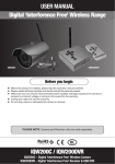
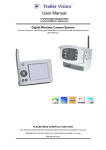
1. Receiver antenna
2. USB out
3. A/V out
4. DC Power
5. Signal LED
Keep WIFI router away from the camera and/or
receiver.
Strong electromagnetic
Keep working motors (hair dryer / heat fan / air
interference near by
conditioner / water pump) or microwave oven
Scan channel(s) been set
Channel(s) disappear
during auto / manual
OFF
Scan or QUAD display
M
4
Strong radio signal near
by
away from the camera and/or receiver.
1
3
Adjust camera antenna and receiver position.
camera and receiver. Or relocate the camera to
proper location.
Receiver
3
is picking up by the receiver, camera Status
Indicator (GREEN LED)will light up.
Draw the camera near the receiver.
Signal been blocked
Signal been blocked
2
First identify the image missing camera, draw the
camera near receiver then pair the camera to
desired channel. See Page 12 {Pairing Camera}
7 6
5
6. Pairing LED
7. Power LED
8. Power supply
9. Phone jack to RCA cable
10. USB to USB Cable
8
9
Go to menu; enable the channel(s). See Page 10
{Setting Auto / Manual Scan Sequence} or detail.
Dim / over bright
Low light vision distance
Ideal low light vision distance is from 9 feet / 3
image at night time
too short / too far.
metres to 24 feet/ 8 metres.
. Adjust the camera to
have camera view fit in this distance.
10
Blank TV screen
shows [USB PC
Camera Mode] only
USB Cable is plugged on
Connecting to TV, always use 5V power adaptor
to power up the receiver. Leave USB cable
unplugged PRIOR to TV connection.
Receiver Function
Buttons no response
16
Getting Start
About Digital Wireless Technology
Step1: Hardware Set Up
About 2.4GHz Digital Wireless Signal
This innovative digital wireless solution integrates advance Frequency Hopping
Spread Spectrum (FHSS) technology. This technology greatly reduce the interference
that comes from other devices using the same radio frequency (2.4GHz), e.g. WIFI,
Bluetooth, Zigbee, cordless phone…etc. You now can enjoy a more pleasant wireless
surveillance quality without flicking and noisy image. However, weaker signal (lag
or still image) can be observed yet from time to time, depending on the environment
where the system is installed.
Complied with FCC part 15.247, ETSI (EN) 300 328, audio / video signals transmitted
out about or over 600 feet / 200 metres in line of sight should be supported. Line of sign
installation, though, is usually not a common practice. Factors affecting transmission
include microwave ovens or other high frequency electromagnetic waves. Reinforced
concrete walls, large scale metal products and metal furniture should not be located
near the camera or the receiver. Water creates an obstacle and should not be placed near.
Human bodies such as a person passing through may cause unstable signal quality
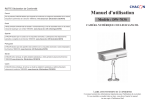
Camera Assembly / Adjustment
A. Loosen U holder screws; slide the sunshield to ideal position.
B. U bracket can be installed on camera top side for ceiling mount.
C. Secure U holder with screws when done.
D. Adjust camera for proper view angle. Secure the stand with T-bolt when done.
Camera Wall Mounting
How to improve the wireless signal quality?
If possible, remove obstacles in between camera and receiver that might reflect the signal.
These could include furniture, cabinets, and walls. If you feel the wireless signal is not
good enough, place the receiver at a new angle or readjust its position to make an
improvement. Or simply relocate the camera closer to the receiver.
Why Image Compression?
In order to provide a private and interference free wireless service, this digital
wireless solution works on a 2Mb narrow hopping band. Different from traditional
2.4GHz analog signal, this digital wireless signal is compressed and presented
as Motion JPEG (MJPEG) format. By digitalizing and compressing the raw analog
data, the bandwidth is used more efficiently and securely. Consequentially, you might
observe an indent image line on a larger display monitor or plasma TV.
A. Secure camera stand on the wall
B. Secure camera U holder to the stand.
C. Adjust proper view angle then secure the joint with T-bolt.
Camera Ceiling Mounting
How to improve the image quality?
On QVGA size (ZOOM, zoom IN), pixel scattering is unavoidable. However, you can try
to zoom out the image to VGA size. By doing so, more pixels can be scattered on the
monitor. To have the best display performance, 32 inch or smaller monitor / TV is
suggested.
15
A. Secure camera stand on the Ceiling
B. Flip camera U holder to camera top, then secure U holder to camera.
C. Adjust proper view angle then secure the joint with T-bolt.
4
Connect to computer via USB
Connecting to TV
Step1: Connecting Devices
Step1: Steps to follow :
Set up Camera
1.Install iSEC Guarding Software
2.Restart Windows
3.Connect Receiver
4.Launch iSEC Guarding
A. Secure the Antenna to the camera
B. Connect power cable to camera DC IN.
5V DC adapter ONLY.
C. Plug on power adapter to wall outlet
D. Camera now is ready to use
A
Set up Receiver
USB
B
AV-Out
AV Mode
Video
Audio
Connect receiver to TV,
leave USB cable UNPLUGGED.
A. Turn on TV and switch to AV mode.
B. Connect AV cable Audio / Video jack to TV AV IN. (Yellow=Video, White=Audio)
C. Connect AV cable headset jack to receiver AV OUT.
D. Connect power cable to receiver DC IN.
DO NOT power up receiver using USB cable.
E. Plug power adapter to wall outlet
F. Receiver now is ready to use
Wireless Connection LED Indicator
When wireless signal is well connected, LED indicators as shown:
Camera:
5
A. Connect Receiver to PC USB port using USB cable.
B. Launch [iSEC Guarding] software.
Using USB output will switch image and system control from receiver
to PC. [iSEC Guarding] software installation CD is provided with the
product. For detail, please refer to [iSEC Guarding Software
Installation Guide].
Leave the A/V cable and 5V DC power adapter UNPLUGGED PRIOR to
USB connection.
Receiver:
14
Reset
Step2: Basic Operation
A. Press
B. System will restore the original factory
default settings
Knowing Receiver Function Button
Up
Reset
Left
Right
M
Zoom
Camera Select /
Pair(Pair mode)
Down
A.Pressing
Menu
(Up / Down / Left / Right),
In Zoom IN mode (ZOOM), pan and tilt the camera
In Menu mode, move between the selections
B.Pressing M (Menu Mode),
Enter / Exit Menu Mode
C.Pressing
(Zoom IN / OUT),
Zoom IN (ZOOM, QVGA size) or Zoom OUT (VGA size) the camera
D.Pressing
(Cam / Pair)
In View mode, manually select among available camera channels
In Pair mode, assign and pair private camera to specified channel
13
6
6
In the View Mode
Signal Indicator
Channel Indicator
1
Pairing Camera(s)
Zoom Indicator
1
This function is available for multi cameras users.
It is highly recommended to pair the camera before hardware installation.
Before pairing the camera, make sure camera is power ON, camera status indicator
as shown:
1
ZOOM
NO SIGNAL
Status Indicator
A. Signal Indicator shows signal strength, more dots means stronger signal.
Signal Level
Indicator
Data Rate
A. Simply pair the camera by selecting the
desired channel in Menu Mode.
B. Only assign one camera to one channel.
Channel memory will be overwritten if
next camera is assigned to same channel.
C. Pairing new camera to channel 3, settings
as shown:
VGA Frame Rate QVGA Frame Rate
Perfect
1062~1280Kbps
5~10Fps
15~30Fps
Good
725~1062Kbps
3~5Fps
12~20Fps
Fair
543~725Kbps
2~4Fps
8~15Fps
Low
250~543Kbps
0~1Fps
0~4Fps
Zero
0~250Kbps
0Fps
0Fps
B. Channel indicator shows the current camera being picked up by the receiver
By pressing
(Cam), you can manually switch among multi cameras.
Or you can set up auto scan in the Menu Mode.
1
60
D. Press
(Pair).
E. System will count down within 60
seconds, system message as shown:
2
F. Within 60-seconds count
down, press the Pair Key
on the back of camera.
Camera 1
3
Camera 2
Pairing key
4
3
7
Camera 3
Camera 4
C. When System Message shows “NO SIGNAL”, it means Service out of Range.
Please refer to Trouble Shooting page.
G. Once pairing
completed,
camera and
receiver status
indicators as
shown.
12
D. Zoom Indicator shows Zoom status
By pressing
(Zoom) on the receiver, you can switch between two resolutions.
Setting QUAD Display
This function is available for multi cameras user. Before setting QUAD display, make sure
all cameras are paired to assigned channels. See [Advance Operation – Pair Camera]
section as a guide.
QUAD display will be restored to one camera display every time after your press
for manual scan.
To display properly, turn all available channels ON PRIOR to entering into QUAD mode.
Audio Vol
10
Scan Time
QUAD
Camera 1 ON
Camera 2 ON
Camera 3 ON
Camera 4 ON
Pair CAM 1 2 3 4
Systern Setup
Factory Reset
CH1
A. Use
to turn all available channels ON.
B. Use
to change Scan Time to QUAD
1
1
Zoom OUT (VGA)
ZOOM
Zoom IN (ZOOM, QVGA)
E. Pan / Tilt
In Zoom IN mode (ZOOM), press
to pan and tilt camera view.
1
ZOOM
1
ZOOM
CH2
C. QUAD display as shown. Unavailable channel will be
displayed as blank screen.
To leave QUAD display, simply press
to go to specific channel.
= CAM4 ;
= CAM3;
= CAM1;
1
ZOOM
1
ZOOM
= CAM2
In QUAD display, speaker will be mute and [ZOOM] / [Pair]
button functions are not available.
CH3
CH4
1
11
ZOOM
8
Step3: Advance Operation
Knowing the Menu
By Pressing M (Menu), you can enter / exit Menu Mode
You can Use
(Left / Right / Up / Down) to select and change
the settings.
Audio Vol
10
Scan Time
OFF
Camera 1 ON
Camera 2 ON
Camera 3 ON
Camera 4 ON
Pair CAM
1234
Reset
Setting Auto / Manual Scan Sequence
This function is available for multi cameras user.
Scan Time will be turn off every time after your press
A. Use
(Left / Right) to change Scan
Time interval from OFF / 5 sec / 10 sec / 15sec.
B. Default setting is OFF, system will not scan
and camera display has to be manually assigned.
Skip Certain Camera(s) During Scan
Before setting Scan and Skip, make sure all cameras are paired to assigned
channels. See next pages for detail.
A. Simply set the skip camera(s) OFF by
pressing
(Left / Right).
B. Skip Camera 2 and 4 during 5 seconds Scan
Time interval, settings as shown:
Setting Audio Volume
You can use
(Cam) for manual scan
(Left / Right) to change Audio Volume from 0 to 20.
TV Display as shown:
1
3
5 Seconds
9
10