1
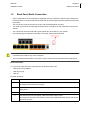
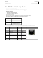
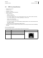
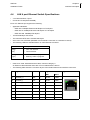
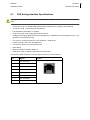
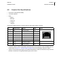
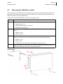
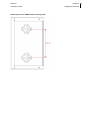
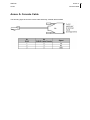
ONE445
Installation Guide
Version: 1.1 - 556370
27 May 2013
ONE445
Copyright, feedback 2
Installation Guide
Document Properties
Subject
ONE445
Manual type
Installation Guide
Version
1.1
Code
556370
Modification date
27 May 2013 ©OneAccess
Copyright Notice
The information and descriptions contained in this publication are the property of OneAccess. Such information and descriptions must not be copied or reproduced by any means, or disseminated or distributed
without the express prior written permission of OneAccess.
This publication could include technical inaccuracies or typographical errors, for which OneAccess never
can or shall be held liable. Changes are made periodically to the information herein; these changes will
be incorporated in new editions of this publication. OneAccess may make improvements and/or changes
in the product(s) described in this publication at any time, without prior notice.
OneOS Operating System
The OneOS is a feature-rich operating system that guarantees a common feature set across the different
OneAccess product lines and a uniform support by maintenance and management tools.
The OneOS manual, which is a separate manual, describes the features of the latest version of the
OneOS operating system.
Your Feedback
Your satisfaction about this purchase is an extremely important priority to all of us at OneAccess. Accordingly, all electronic, functional and cosmetic aspects of this new unit have been carefully and thoroughly
tested and inspected. If any fault is found with this unit or should you have any other quality-related comment concerning this delivery, please submit the Quality Comment Form on our web page at
www.oneaccess-net.com → Support → Quality Comment Form.
ONE445
Table of contents 3
Installation Guide
Table of contents
1
Safety Instructions ..............................................................................................5
1.1
1.2
1.3
1.4
1.5
2
Directives and Standards..................................................................................12
2.1
2.2
2.3
2.4
2.5
2.6
3
Power Requirements................................................................................................ 41
Dimensions............................................................................................................... 41
Installing the ONE445 ........................................................................................42
6.1
6.2
6.3
7
Connectors of the ONE445 Back Panel ................................................................... 29
WAN Ethernet Interface Specification ...................................................................... 31
VDSL Line Specifications ......................................................................................... 32
LAN 4 port Ethernet Switch Specifications............................................................... 33
WLAN Interface Specifications................................................................................. 34
ISDN BRI Interface Specifications............................................................................ 35
FXS Analog Interface Specifications ........................................................................ 38
Console Port Specifications ..................................................................................... 39
Technical Characteristics .................................................................................40
5.1
5.2
6
What is the ONE445................................................................................................. 18
Hardware Description............................................................................................... 20
The Front Panel LED Indicators ............................................................................... 21
Rear view of the ONE445......................................................................................... 24
The ONE445 Motherboard ....................................................................................... 27
Interface Description .........................................................................................28
4.1
4.2
4.3
4.4
4.5
4.6
4.7
4.8
5
Statements ............................................................................................................... 13
Environmental Information ....................................................................................... 14
Safety Compliance ................................................................................................... 15
Over-Voltage and Over-Current Protection Compliance .......................................... 15
EMC Compliance ..................................................................................................... 15
Environmental Compliance ...................................................................................... 16
Device Description ............................................................................................17
3.1
3.2
3.3
3.4
3.5
4
Safety Information / Consignes de Sécurité ............................................................... 6
Unpacking .................................................................................................................. 8
Selecting a Site .......................................................................................................... 9
Connection Precautions ........................................................................................... 10
Back Panel Earth Connection .................................................................................. 11
Opening and Closing the Housing............................................................................ 43
Mounting the ONE445 on a Wall.............................................................................. 44
Mounting an Anti-Theft Security Cable..................................................................... 46
Powering up the ONE445 ..................................................................................47
Annex .................................................................................................... 48
Annex A:Console Cable ..........................................................................................49
ONE445
Table of contents 4
Installation Guide
Index ...................................................................................................... 50
ONE445
Installation Guide
1
Chapter 1 5
Safety Instructions
Safety Instructions
This chapter gives some important safety instructions to take into account when using and installing the
ONE445. The following gives an overview of this chapter:
•
1.1 - Safety Information / Consignes de Sécurité on page 6
•
1.2 - Unpacking on page 8
•
1.3 - Selecting a Site on page 9
•
1.4 - Connection Precautions on page 10
•
1.5 - Back Panel Earth Connection on page 11
ONE445
Chapter 1 6
Installation Guide
1.1
Safety Instructions
Safety Information / Consignes de Sécurité
Information to user
Informations envers l'utilisateur
•
Changes or modifications not expressly
approved by the party responsible for compliance could void the user's authority to operate
the equipment.
•
•
The external power supply may be delivered
together with the ONE445.
Tout changement ou modification non
expressément approuvé par l'instance compétente responsable pour la vérification de la
conformité de l'équipement peut invalider
l'autorisation accordée à l'utilisateur de mettre
l'équipement en service.
•
L'adaptateur ou le câble d'alimentation électrique prescrit par OneAccess peut être livré
d'origine ou non avec l'équipement.
•
En France, l’ utilisation de l’ option WiFi de cet
équipment est restreinte à un usage intérieur.
Connecting the power supply
Raccordement à l'alimentation
To connect the power supply, always respect following steps:
Pour alimenter l'équipement, toujours respecter
les étapes suivantes:
1. Plug power supply connector in the corresponding device's input power connector.
1. Enfichez le connecteur d'alimentation dans le
connecteur d'entrée d'alimentation correspondant de l'équipement.
2. Secure power supply cable by looping it once
around holding clip foreseen on device to
avoid unwanted power supply cable disconnection. (Only valid if device is equipped with
such a holding clip).
3. Connect the power supply plug to the electrical
power network; refer to 5.1 - Power Requirements on page 41.
2. Rebouclez le câble d'alimentation autour de la
bride de maintien prévue à cet effet sur le panneau arrière pour éviter l'arrachage accidentel
du connecteur d'alimentation. (Uniquement
pour les équipements qui sont pourvus d'une
bride de maintien)
3. Branchez la fiche d'alimentation au réseau
d'alimentation électrique (voir 5.1 - Power
Requirements on page 41).
ONE445
Chapter 1 7
Installation Guide
Safety Instructions
Over-current Protection
Protection contre les surcharges
•
Do not use another type of power supply than
the one delivered or prescribed by OneAccess.
•
Ne pas utiliser d'autre type d'adaptateur que
celui livré ou prescrit par OneAccess.
•
•
Always use a power cable approved for this
use as the one delivered or prescribed by
OneAccess.
Toujours utiliser un type de câble d'alimentation agréé pour cet usage comme celui livré ou
prescrit par OneAccess.
•
•
This device requires that the building's electrical installation is designed for protection
against short-circuit (over-current) protection.
A fuse or circuit breaker no larger that 10A
must be used on the phase conductor (AC) or
the active conductor with respect to the protective earth (DC).
La protection contre les courts-circuits de cet
équipement dépend de l'installation électrique
du local à laquelle il est raccordé. Vérifier
qu'un fusible ou disjoncteur de maximum 10A
est installé sur le conducteur de phase (AC) ou
le conducteur actif par rapport à la terre (DC).
Use Precautions
Précautions d'usage
•
•
To avoid damage to the device, please
observe all procedures described in this chapter.
Pour éviter d'endommager l'équipement,
veuillez respecter toutes les procédures
décrites dans ce chapitre.
•
Disconnect the power supply before installing, •
moving or servicing the device. Always disconnect the electrical power supply first.
•
Ensure that the unit and its connected equipment all use the same power and earth wiring,
to reduce noise interference and possible
safety hazards caused by differences in earth
potentials.
Débranchez l'alimentation de la prise réseau
électrique avant d'installer, déplacer ou intervenir sur l'équipement. Débranchez toujours
l'alimentation réseau électrique en premier.
•
•
If an earth stud is present, it is essential that
the earth stud, marked with
, is effectively
connected to earth. Otherwise, in case of electrical problems, other devices connected to the •
ONE445 could be damaged.
Also refer to 1.5 - Back Panel Earth Connection on page 11.
Assurez-vous que l'équipement et ses
périphériques soient tous branchés sur un
même réseau d'alimentation électrique et une
équipotentielle de terre afin de réduire les
interférences perturbatrices et de possibles
risques de sécurité causés par des différences
de potentiel entre prises de terre.
Si présente, il est essentiel que la borne de
terre, marquée avec
, soit effectivement
raccordée à la terre. Autrement, en cas de
défaut électrique, d'autres équipements connectés au ONE445 pourraient être endommagés.
Voir aussi 1.5 - Back Panel Earth Connection
on page 11.
ONE445
Chapter 1 8
Installation Guide
1.2
Safety Instructions
Unpacking
Checking the shipping carton
Rough handling during shipping causes most early failures. Before installation, check the shipping carton for signs of damage:
•
If the shipping carton is damaged, please place a claim with the carrier company immediately.
•
If the shipping carton is undamaged, do not dispose of it in case you need to store the unit or ship it
in the future.
ONE445
Chapter 1 9
Installation Guide
1.3
Safety Instructions
Selecting a Site
Warning
Avertissement
•
Always place the unit in such a way that the air
vents are not blocked.
•
Placez toujours l'appareil de sorte que les
ouïes d'aération ne soient pas obturées.
•
To improve the quality of radio transmission,
be careful to install the product in a location
with limited electromagnetic shields such as
metallic frames, cabinets, … Otherwise, an
external antenna with an extension cable
should be used.
•
Pour optimiser la qualité de la transmission
radio, prenez la peine d'installer l'appareil
dans un endroit peu protégé contre les
champs électromagnétiques en évitant les
structures métalliques, armoires, …
Dans le cas contraire, une antenne externe
avec un câble d'extension devrait être utilisée.
Caution
Attention
•
Install the unit in an area free of extreme temperatures, humidity, shock and vibration. Position it so that you can easily see and access
the front panel and its control indicators. Leave
enough clearance at the back for cables and
wires.
•
•
The AC/DC adapter is used to switch the
device on or off by plugging it in or disconnect- •
ing it, respectively.
The socket outlet shall be installed near the
device and easily accessible.
Installez l'appareil dans une zone exempte de
températures extrêmes, d'humidité, de chocs
et de vibrations. Positionnez-le de sorte que
vous puissiez aisément accéder au panneau
avant et voir ses témoins de contrôle. Laissez
suffisamment d'espace à l'arrière pour les fils
et les câbles.
Le convertisseur d’alimentation AC/DC est utilisé comme dispositif interrupteur.
La prise de courant doit être installée à proximité de l’appareil et facilement accessible.
ONE445
Chapter 1 10
Installation Guide
1.4
Safety Instructions
Connection Precautions
ESD WARNING
The circuit boards are sensitive to electrostatic discharges (ESD) and should be handled with care. It is
advisable to ensure an optimal electrical contact between yourself, the working area and a safety ground
before touching any circuit board. Take special care not to touch any component or connector on the
circuit board.
NOTE
This unit may be powered by an IT power system.
For the definition of an IT power system, refer to Annex V - AC power distribution systems of EN609501, section V.4 IT power distribution systems.
The connectors of the ONE445 should only be connected to the following circuit types:
Interface type
Interface identification
Connector type
Circuit type
ADSL2+/VDSL2
VDSL
RJ11
TNV-3
RS2321
CONSOLE
RJ45
SELV
LAN2
ETH 1/0
RJ45
SELV
LAN3
ETH 0/0 ... 0/3
RJ45
SELV
FXS
FXS 5/4 ... 5/7
RJ11
TNV-2
ISDN BRI
BRI 5/0 ... 5/3
RJ45
SELV
1. V.24
2. 10/100 Base T port
3. 10/100/1000 Mbps interface
•
Inside building circuit: Circuit remaining inside building and not subject to telecom network primary
nor secondary lightning strikes.
•
Outside building circuit: Circuit routed going outside building and possibly subject to telecom network
secondary lightning strikes.
•
SELV or Safety Extra Low Voltage: Inside building circuit designed to not exceed safe voltage value.
-
TNV-2: Inside building circuit exceeding SELV voltage limits but respecting TNV voltage limits
-
TNV-3: Outside building circuit exceeding SELV voltage limits but respecting TNV voltage limits
ONE445
Chapter 1 11
Installation Guide
1.5
Safety Instructions
Back Panel Earth Connection
•
Some configurations of the ONE445 are equipped with FXS interfaces, and will need a hard wired
Protective Earth connection between the earth stud on the back panel and the protective earth of the
load centre.
This connection must be permanent, secure and protected against corrosion.
•
The earth wire must be mechanically protected when crossing floors and walls and never be built
directly.
•
The connection must be made with a green/yellow wire of at least a 1 mm² section.
•
The following figure indicates the location of the earth stud on the back panel:
•
For safety reasons it is essential that the hard wired Protective Earth connection is installed before
connections are made to any of the FXS ports.
•
The hard wired Protective Earth connection must be carried out by authorized service personnel.
Earth Connection
To connect an earth wire to the clinching stud on the back panel, use:
•
1 M3 spring or lock washer
•
1 M3 ring tongue
•
1 M3 nut
Proceed as follows:
Step
Action
1
If not already done so: the earth cable that will be connected to the clinching stud, must
be equipped with the M3 ring tongue.
2
Slide the M3 ring tongue over the clinching stud so that it makes direct contact with the
back panel.
3
Slide the M3 spring/lock washer over the clinching stud.
4
Use the M3 nut to fix everything; make sure that it is firmly fixed.
This makes sure that the three parts are firmly fixed against the back panel, and cannot
get loose anymore.
ONE445
Installation Guide
2
Chapter 2 12
Directives and Standards
Directives and Standards
This chapter details the list of standards, which the ONE445 complies with. The following gives an overview of this chapter:
•
2.1 - Statements on page 13
•
2.2 - Environmental Information on page 14
•
2.3 - Safety Compliance on page 15
•
2.4 - Over-Voltage and Over-Current Protection Compliance on page 15
•
2.5 - EMC Compliance on page 15
•
2.6 - Environmental Compliance on page 16
ONE445
Chapter 2 13
Installation Guide
2.1
Directives and Standards
Statements
www.oneaccess-net.com → Support → Download Center → Technical Downloads →
Choose a product → Choose Product certificates→ Search
Hereby, OneAccess declares that this ONE445 complies with the essential requirements and other relevant provisions of Directive 1999/5/EC.
Hierbij verklaart OneAccess dat deze ONE445 overeenstemt met de essentiële vereisten en andere relevante bepalingen van Richtlijn 1999/5/EC.
Par la présente, OneAccess déclare que ce ONE445 est en conformité avec les exigences essentielles
et autres articles applicables de la Directive 1999/5/EC.
Hiermit, OneAccess erklärt daß dieser ONE445 in Fügsamkeit ist mit den wesentlichen Anforderungen
und anderen relevanten Bereitstellungen von Direktive 1999/5/EC.
Mediante la presente, OneAccess declara que el ONE445 cumple con los requisitos esenciales y las
demás prescripciones relevantes de la Directiva 1999/5/CE.
A OneAccess declara que o ONE445 cumpre os principais requisitos e outras disposições da Directiva
1999/5/EC.
Col presente, OneAccess dichiara che questo ONE445 è in acquiescenza coi requisiti essenziali e stipulazioni attinenti ed altre di Direttivo 1999/5/EC.
Με το παρόν η OneAccess δηλώνει ότι το ONE445 είναι συμμορφούμενο με τις βασικές απαιτήσεις και
με τις υπόλοιπες σχετικές διατάξες της οδηγίας 1999/5/EC.
ONE445
Chapter 2 14
Installation Guide
2.2
Directives and Standards
Environmental Information
The crossed-out wheeled bin means that within the European Union the product must be taken to separate
collection at the product end-of-life. This applies to the device but also to any accessories marked with this symbol.
Do not dispose of these products as unsorted municipal waste.
If you need more information on the collection points where you can present your end-of-life equipment for
recycling, please contact your local importer.
For Belgium, you can contact [email protected].
De doorstreepte container wil zeggen dat binnen de Europese gemeenschap het product voor gescheiden afvalverzameling moet
worden aangeboden aan het einde van de levensduur van het product. Dit geldt voor het toestel, maar ook voor alle toebehoren
die van dit symbool voorzien zijn. Bied deze producten niet aan bij het gewone huisvuil.
Indien u meer informatie wenst over het inzamelpunt waar u afgedankte apparatuur kan aanbieden voor recyclage, gelieve dan
uw lokale importateur te contacteren.
Voor Belgie kan u contact opnemen met [email protected].
Le symbole de la poubelle sur roues barrée d'une croix signifie que ce produit doit faire l'objet d'une collecte sélective en fin de vie
au sein de l'Union Européenne. Cette mesure s'applique non seulement à votre appareil mais également à tout autre accessoire
marqué de ce symbole. Ne jetez pas ces produits dans les ordures ménagères non sujettes au tri sélectif.
Si vous souhaitez plus d'information concernant le point de collecte où vous pouvez apporter vos appareils usagés afin qu'ils soient
recyclés, veuillez contacter votre importateur local.
Pour la Belgique, vous pouvez prendre contact avec [email protected].
Das Symbol der durchgestrichenen Abfalltonne auf Rädern bedeutet dass das Produkt in der Europäischen Union einer
getrennten Mülsammlung zugeführt werden muss. Dies gilt sowohl für das Produkt selbst, als auch für alle mit diesem Symbol
gekennzeichneten Zubehörteile. Diese Produkte dürfen nicht über den unsortierten Hausmüll entsorgt werden.
Falls Sie weitere Auskünfte brauchen im Betracht der Sammelplätze für ausrangierte Apparate, wenden Sie sich bitte an Ihren
örtlichen Importeur.
Für Belgien, bitte kontaktieren sie [email protected].
ONE445
Chapter 2 15
Installation Guide
2.3
Directives and Standards
Safety Compliance
•
EN60950-1: Safety of information technology equipment, including electrical business equipment.
•
Class II equipment.
2.4
Over-Voltage and Over-Current Protection Compliance
The over-voltage and over-current protection complies with ITU-T K.44 and ETSI EN 300 386 recommendations.
2.5
EMC Compliance
•
CE
•
EN55022 B Emissions
•
EN55024 Immunity
•
EN61000-3-2 Harmonics
•
EN61000-3-3 Voltage fluctuations and flicker
•
EN61000-4-2 ESD
•
EN61000-4-3 Radiated immunity
•
EN61000-4-4 EFT/burst
•
EN61000-4-5 Surge
•
EN61000-4-6 Conducted immunity
•
EN61000-4-8 Power magnetic field immunity
•
EN61000-4-11 Voltage dips & drops
•
EN300386 EMC Requirements
ONE445
Chapter 2 16
Installation Guide
2.6
Directives and Standards
Environmental Compliance
•
Storage conditions: ETSI ETS 300 019-1-1 Class 1.1. In addition, the storage temperature has to be
between -25 and +70°C, with a relative humidity between 0 and 95% non-condensing.
•
Transport conditions: ETSI ETS 300 019-1-2 Class 2.3.
•
Stationary use conditions: ETSI ETS 300 019-1-3 Class 3.1. In addition, a relative humidity between
5 and 80% non-condensing and an ambient operational temperature between 0°C and 45°C is supported.
•
International protection (IP) class of protection against solid and liquids: IP30
ONE445
Installation Guide
3
Chapter 3 17
Device Description
Device Description
This chapter describes the ONE445 front and back panels, and the associated technical characteristics.
The following gives an overview of this chapter:
•
3.1 - What is the ONE445 on page 18
•
3.2 - Hardware Description on page 20
•
3.3 - The Front Panel LED Indicators on page 21
•
3.4 - Rear view of the ONE445 on page 24
•
3.5 - The ONE445 Motherboard on page 27
ONE445
Chapter 3 18
Installation Guide
3.1
Device Description
What is the ONE445
Managed Voice and Data Services for Small and Medium Businesses
Targeting the small enterprises and enterprise branch offices, the OneAccess ONE445 Multi-Service
Access Router is a high performance, one box solution for unified voice and data managed services. The
ONE445 is an integrated device for voice, data, security and WAN uplink redundancy. It integrates
OneAccess VoIP technology and enterprise-class data services to deliver high service density over
ADSL & VDSL2 broadband technologies.
The ONE445 enables service providers to deliver hosted and managed communication services combining data routing, security, voice services, Wireless LAN and multiple WAN access. As Service Providers strive to lower operations costs and generate new revenues, the flexibility and service density of
the ONE445 provide a cost-effective solution to address the communications needs of the enterprise
and leverage the growing SaaS Cloud infrastructure.
The flexible connectivity of the ONE445 provides a seamless migration from current ADSL to the next
generation high-performance VDSL2 to address the increasing requirements of bandwidth-hungry applications. The ONE445 is a perfect fit for fixed line operators, mobile operators and ISPs targeting small
enterprises or branch offices with a portfolio of hosted and cloud-based services.
Voice Service Agility
The ONE445 is an agile platform with integrated voice capabilities that enables service providers to :
•
migrate legacy ports (analog, ISDN) to VoIP networks
•
develop innovative SIP-based voice services including hosted communications and SIP Trunking
services
•
deliver an all in one solution including a call control platform that supports enterprise-class IP-based
communication services.
Featuring either 4 BRI ports or a combination of 4 BRI and 4 FXSports, the integrated VoIP gateway connects analog terminals, ISDN endpoints or PBXs to the VoIP network. In addition the ONE445 provides
advanced voice routing functionalities along with backup and call admission control capabilities to
ensure a high quality and uninterrupted service.
For hosted communications and SIP trunking services, the onboard SBC Nano module acts as an enterprise SBC to secure the end-to-end SIP-based voice services, address interoperability issues inherent
in SIP networks and ensure voice quality. With its Dial Tone Continuity feature, the SBC Nano helps to
ensure voice service resiliency by enabling both internal and external calls during network outages.
Leveraging the ONE445 platfrom the optional , Integrated Business Communications (IBC) software
turns the ONE445 into a full fledged IP-PBX with embedded Unified Communications. The IBC option
takes full advantage of the service convergence to provide enterprise-class communication services in
combination with the ONE445 data service capabilities including broadband access and wireless LAN.
ONE445
Installation Guide
Chapter 3 19
Device Description
Enterprise Class Data Services
The ONE445 offers service providers the flexibility to support a wide variety of local and wide area
access connectivity speeds and types. For the access network, it combines ADSL and VDSL2 to provide
connectivity to the existing ADSL infrastructure and support next generation VDSL2. The main VDSL2
interface offers speeds up to 100Mbps downstream and upstream. A FE WAN port offers network redundancy and enables a cost effective high speed back-up and high availability capability in support of stringent service level agreements or business critical application services.
All the enterprise communication infrastructure, including IP PBXs, servers and switches are connected
to the wide area network via the in-built 4 port Gigabit Ethernet switch of the ONE445. With the WLAN
option, OneAccess brings a 802.11 b/g/n WLAN interface into the ONE445 to deliver secured, high-performance wireless networking. State-of-the art authentication schemes are supported such that public
hotspot services can be delivered over the same platform without compromising the security of the private wireless or wired infrastructure.
ONE445
Chapter 3 20
Installation Guide
3.2
Hardware Description
The ONE445 motherboard is by default equipped with the following interfaces:
•
Console port
•
Managed 4 port switch with 4Gb Ethernet ports 0/0 ... 0/3
•
UTP Fast Ethernet port 1/0
•
ISDN BRI connectors
Aditionally, an ADSL2+/VDSL2 port (single pair) is present.
Optional interfaces are:
•
FXS connectors
•
Wireless LAN 802.11b/g/n
Device Description
ONE445
Chapter 3 21
Installation Guide
3.3
Device Description
The Front Panel LED Indicators
This section gives an overview of the front panel LEDs and what they indicate. The following gives an
overview of this section:
•
3.3.1 - Introducing the Front Panel LEDs on page 22
•
3.3.2 - LED states on page 23
ONE445
Chapter 3 22
Installation Guide
3.3.1
Device Description
Introducing the Front Panel LEDs
Front panel
When all the connections are made and the ONE445 is powered, the LEDs on the front panel reflect the
actual status of the device.
The following figure shows the front panel LED indicators of the ONE445:
LED states
One front panel LED can reflect different status modes by the way it lights up. The front panel LEDs can
light up as follows:
LED state
LED duty cycle
Description
OFF
0%
The LED never lights up.
ON
100 %
The LED lights up continuously.
blinking
50 %
The LED is as much lit as it is out.
ONE445
Chapter 3 23
Installation Guide
3.3.2
Device Description
LED states
The state of the LEDs indicate the following:
LED name
Colour
Description
Status
Bicolour
•
OFF: No input power.
•
ON - Red: Switched on and not operational.
•
Blinking Green: (Re)boot in progress.
•
ON - Green: Switched on and operational.
•
OFF: The WAN interface is not configured.
•
ON - Red: The WAN interface does not get any reaction
from the other side of the link (on any of the line pairs in
case of DSL).
•
Blinking Green: The WAN synchronisation is in progress.
•
ON - Green: The WAN link is synchronised.
•
OFF: not used.
•
ON - Green: All IP interfaces are up.
•
ON - Red: All IP interfaces are down.
•
Blinking Green: At least one IP interface is not up and at
least one IP interface is up. Not applicable if no IP interface
is configured.
•
OFF: Interface not configured or configured and down.
•
ON - Green: Interface configured and up without traffic.
•
Blinking green: Interface configured and up with traffic.
•
OFF: No auto configuration.
•
ON - green: Auto configuration successfully completed.
•
Blinking green: Auto configuration in progress.
•
OFF: No voice service on any of the voice ports
•
ON - Green: Voice service operational on any of the
voice ports.
•
Blinking green: No default at least one voice call in
progress.
•
ON - Red: Voice service not fully operational (Gateway
deregistered or no more configured voice port or layer1
on BRI/PRI interface is down or no configured dial-peer
voip)
•
ON - Orange : Specific status when Voice Test service is
configured and it didn’t work at the end of installation (no
gateway available and only local call available).
VDSL
IP
WLAN
Aux
Com
Bicolour
Bicolour
Green
Green
Bicolour
ONE445
Chapter 3 24
Installation Guide
3.4
Device Description
Rear view of the ONE445
This section describes the types of ONE445 back panels, so that the user can identify the interface type
and port numbering.
The following gives an overview of the different models of the ONE445:
•
ONE445-4B AV2 4TE on page 25
•
ONE445-4B-4V AV2 4TE on page 26
ONE445
Chapter 3 25
Installation Guide
Device Description
ONE445-4B AV2 4TE
The following figure shows the back panel:
Following connectors are present:
Interface type
Interface identification
Type
Function
VDSL
VDSL
RJ11
VDSL/ADSL line connector
Console
CONSOLE
RJ45
V.24 DTE interface
Ethernet
ETH 1/0
RJ45
Fast Ethernet LAN connector
4 port Ethernet
switch
ETH 0/0 ... 0/3
RJ45
Gb Ethernet LAN connectors
ISDN BRI
BRI 5/0 ... 5/3
RJ45
ISDN BRI connection, NT pinout
WLAN
-
-
Wireless LAN fixed antennas
Power
12VDC-2,8A
DC input
jack
Power input
Screw
hole
Earth connection
Earth stud
ONE445
Chapter 3 26
Installation Guide
Device Description
ONE445-4B-4V AV2 4TE
The following figure shows the back panel:
Following connectors are present:
Interface type
Interface identification
Type
Function
VDSL
VDSL
RJ11
VDSL/ADSL line connector
Console
CONSOLE
RJ45
V.24 DTE interface
Ethernet
ETH 1/0
RJ45
Fast Ethernet LAN connector
4 port Ethernet
switch
ETH 0/0 ... 0/3
RJ45
Gb Ethernet LAN connectors
FXS
FXS 5/4 ... 5/7
RJ11
4 analog telephone interfaces; on
daughterboard
ISDN BRI
BRI 5/0 ... 5/3
RJ45
ISDN BRI connection, NT pinout
WLAN
-
-
Wireless LAN fixed antennas
Power
12VDC-2,8A
DC input
jack
Power input
Screw
hole
Earth connection
Earth stud
ONE445
Chapter 3 27
Installation Guide
3.5
Device Description
The ONE445 Motherboard
The figure below shows the motherboard, and the position of the straps on the ONE445 motherboard:
ONE445
Installation Guide
4
Chapter 4 28
Interface Description
Interface Description
This chapter gives an overview of the different connectors on the back of the ONE445. The following
gives an overview of this chapter:
•
4.1 - Connectors of the ONE445 Back Panel on page 29
•
4.2 - WAN Ethernet Interface Specification on page 31
•
4.3 - VDSL Line Specifications on page 32
•
4.4 - LAN 4 port Ethernet Switch Specifications on page 33
•
4.5 - WLAN Interface Specifications on page 34
•
4.6 - ISDN BRI Interface Specifications on page 35
•
4.7 - FXS Analog Interface Specifications on page 38
•
4.8 - Console Port Specifications on page 39
ONE445
Chapter 4 29
Installation Guide
4.1
Interface Description
Connectors of the ONE445 Back Panel
The following table gives an overview of the connectors located at the back of the ONE445 and explains
their function:
Interface identification
Interface function
VDSL
This RJ11 connector is the VDSL line connector.
Connect one side of a VDSL line cable to the VDSL connector of the ONE445, and
the other side to a VDSL outlet.
For optimum performance, the used line pairs have to be properly twisted.
Refer to 4.3 - VDSL Line Specifications on page 32 for more information.
CONSOLE
This RJ45 connector is a V.24 DTE interface. This enables you to manage the
ONE445 locally.
Refer to 4.8 - Console Port Specifications on page 39 for more information.
ETH 1/0
This is a Fast Ethernet UTP slot. It can backup the VDSL interface.
For certain configurations, the Fast Ethernet Interface can be configured as a LAN
Interface.
Connect one side of an Ethernet LAN cable to the ETH 1/0 connector of the
ONE445 and the other side to an Ethernet network outlet. The ETH 1/0 interface
supports 10/100 Mbps auto-sense and auto cross-over.
Refer to 4.2 - WAN Ethernet Interface Specification on page 31 for more information.
ETH 0/0 ... 0/3
These RJ45 connectors are Gb Ethernet LAN connectors. There are 4 Ethernet
LAN connectors on the ONE445. The Ethernet switch is VLAN manageable.
Connect one side of an Ethernet LAN cable to a LAN connector of the ONE445
and the other side to an Ethernet network outlet. Each LAN interface supports 10/
100/1000 Mbps auto-sense and auto cross-over.
Refer to 4.4 - LAN 4 port Ethernet Switch Specifications on page 33 for more information.
BRI
5/0 ... 5/3
These RJ45 connectors are the ISDN BRI connectors; 4 BRI connectors are
present.
Connect one side of an ISDN cable to an ISDN BRI connector of the ONE445 and
the other side to an ISDN outlet.
Refer to 4.6 - ISDN BRI Interface Specifications on page 35 for more information.
FXS
5/1 ... 5/4
These RJ45 connectors enable the connection of up to 4 analog telephones thus
providing up to 4 analog voice interfaces.
The earth stud on the back panel of the ONE445 must permanently be connected
to the main protective earth.
Refer to 4.7 - FXS Analog Interface Specifications on page 38 for more information.
ONE445
Chapter 4 30
Installation Guide
Interface Description
Interface identification
Interface function
WLAN
The WLAN antennas are non-detachable. Raise them in a vertical position.
Refer to 4.5 - WLAN Interface Specifications on page 34 for more information.
12VDC-2,8A
This is the power input. Insert the plug of the external power supply in this socket.
Secure the power supply connection by installing the DC power supply cord into
the holding clip provided on the back panel.
Refer to 5.1 - Power Requirements on page 41 for the power specifications of the
ONE445.
This is the earth stud. Connect the earth wire to this stud. Refer to 1.5 - Back Panel
Earth Connection on page 11 for more information.
Contact the appropriate electrical inspection authority or an electrician if you are
uncertain that suitable grounding is available.
ONE445
Chapter 4 31
Installation Guide
4.2
Interface Description
WAN Ethernet Interface Specification
•
Connector: RJ45 (EIA/TIA 568B)
•
Cable to be used: standard Ethernet cable, minimum category 5
•
Applicable standards:
-
IEEE 802.3 (10Mbps Ethernet)
-
IEEE 802.3u (100Mbps Ethernet)
•
10/100 Mbps auto-sense
•
Auto cross-over DTE/DCE (MDI/MDI-X, for connection to a terminal or switch)
•
The following LEDs are available built-in on the Ethernet connector:
Colour
Description
Green
•
OFF: link inactive.
•
ON: link active.
•
OFF: no traffic in progress.
•
ON: traffic in progress.
Yellow
The following table shows the connector layout of the RJ45 Ethernet LAN interface connector:
Pin
Signal
DTE
DCE
1
transmit (+)
Out
In
2
transmit (-)
Out
In
3
receive (+)
In
Out
4
not used
-
5
not used
-
6
receive (-)
In
7
not used
-
8
not used
-
Out
Figure
ONE445
Chapter 4 32
Installation Guide
4.3
Interface Description
VDSL Line Specifications
•
Single pair line access
•
Connector: RJ11
•
Impedance: 135 ohm
•
Cable to be used: CAT5E twisted pair
•
Coding compliant to:
•
-
ANSI T1.413 Issue 2
-
ETSI TS 101 388 v1.3.1
-
ITU-T G.992.1 (ADSL G.dmt), ITU-T G.992.2 (ADSL G.Lite), ITU-T G.992.3 (ADSL G.dmt.bis),
ITU-T G.992.4 (ADSL2), ITU-T G.992.5 (ADSL2plus) - annex A & B
-
ADSL2+ Annex M (optional)
-
ADSL EOC and HLOG (attenuation)
-
ITU-T G.993.1 (VDSL), ITU-T G.993.2 (VDSL2); VDSL2 profiles 8a, 12a, 17a & 30a annex A & B
with ADSL2+ fallback
-
VDSL2 Interop: Ikanos and Broadcom (UPBO and EL)
Performance monitoring: compliant G.826 (errored seconds, severely errored seconds, unavailability
seconds)
The line connector lay-out
The following table shows the connector layout of the RJ11 line connector:
Pin
Signal
2
Tip
3
Ring
Figure
ONE445
Chapter 4 33
Installation Guide
4.4
Interface Description
LAN 4 port Ethernet Switch Specifications
•
4 10/100/1000 Base T ports
•
Connectors: RJ45 (EIA/TIA 568B)
Each UTP Ethernet port supports the following:
•
Applicable standards:
-
IEEE 802.3 10Mbps Ethernet Half Duplex or Full Duplex
-
IEEE 802.3u 100Mbps Ethernet Half Duplex or Full Duplex
-
IEEE 802.3ab 1000Mbps Full duplex
•
10/100/1000 Mbps auto-sense
•
The maximum MTU size is at least 1600 bytes
•
Auto cross-over DTE/DCE (MDI/MDI-X for automatic connection to a terminal or switch)
•
The following LEDs are available built-in on each Ethernet connector:
Colour
Description
Green
(left1)
•
OFF: link inactive.
•
ON: link active.
Yellow
(right1)
•
OFF: no traffic in progress.
•
Blinking: traffic in progress.
1. Defined as looking from the back.
•
Cable to be used: standard ethernet cable, minimum category 5.
An Ethernet cable with label 4022 991 V00 is included with the device.
•
The following table shows the connector layout of the RJ45 Ethernet LAN interface connectors:
Pin
Signal 10/100 BASE-T
DTE
DCE
Signal 1000 BASE-T
MDI
MDI-X
1
transmit (+)
Out
In
BI DA+
BI DB+
2
transmit (-)
Out
In
BI DA-
BI DB-
3
receive (+)
In
Out
BI DB+
BI DA+
4
not used
-
BI DC+
BI DD+
5
not used
-
BI DC-
BI DD-
6
receive (-)
In
BI DB-
BIDA-
7
not used
-
BI DD+
BIDC+
8
not used
-
BI DD-
BI DC-
Out
Figure
ONE445
Chapter 4 34
Installation Guide
4.5
Interface Description
WLAN Interface Specifications
•
Compatible with IEEE 802.1b/g/n (mode can be forced via configuration)
•
Compliant with the IEEE 802.11-2005 recommendation
•
Network topology: access point
•
Frequency: 2.4 - 2.4835 GHz
•
Modulation: CCK, OFDM
•
Dual fixed antennas
•
Channel selection: range of 1-14 (channels 12, 13, 14 can be barred for compatibility with North
American and European requirements)
•
Optional deactivation of broadcast SSID (BSSID), Supports at least 3 SSID ‘s
•
Emission power: up to 20 dBm (16 dBm at 54 Mbps), can be reduced via configuration command
•
Encryption options WEP, WPA 1.2 (TKIP) and WPA 2.0 (802.11i, AES-CCMP)
•
WEP key length: 64, 128, 256 bits
•
Up to 4 WEP keys configurable
•
Authentication options WPA-PSK (pre-shared key) and 802.1x with a RADIUS server
•
802.1x authentication via PEAP, EAP-SIM, EAP-TLS and EAP-TTLS
•
WMM QoS
•
Power save mode: legacy power save and U-APSD (Unscheduled Automatic Power Save Delivery)
ONE445
Chapter 4 35
Installation Guide
4.6
Interface Description
ISDN BRI Interface Specifications
Specifications
•
The ONE445 motherboard is equipped with 4 ISDN BRI interfaces.
•
The connector layout is NT, which means that a straight cable is required for PBX connection, and a
crossed ISDN cable is required for public ISDN network connection.
•
Compliant with ITU-T I.430 section 10
•
Connector: RJ45 connector, 1 connector per interface
•
Cable to be used: shielded cable
•
The factory configuration of these interfaces is T0 mode (connection to PBX). Do not connect the
interfaces with a public ISDN access without ensuring that the strap positions are correct. The product can be irreversibly damaged otherwise.
•
You can connect/disconnect the power supply of all ISDN ports by using the command CLI(voiceport)# [no] power-source-one without changing the default factory strap settings.
•
Cables connected to the T0/S0 (ISDN/BRI) interfaces must always be shielded, in order to respect
the environmental norm.
Mother board connectors
The following table shows the connector layout of the RJ45 ISDN connector:
Pin
NT function
Figure
1
not connected
-
2
not connected
-
3
Receive A (+)
input
4
Transmit A (+)
output
5
Transmit B (-)
output
6
Receive B (-)
input
7
not connected
-
8
not connected
-
ONE445
Installation Guide
Chapter 4 36
Interface Description
Straps
The 4 ISDN interfaces each have a strap, ST13, ST14, ST15 ST16.
These straps make it possible to configure the following options:
•
100 Ohms impedance adaptation
•
Power-feeding for ISDN phones
Refer to 3.5 - The ONE445 Motherboard on page 27 for the position of these straps.
Description
The straps allow:
•
To connect a 100 Ohms impedance adaptation or not. The straps can be used in sending, in receiving
or in both sending and receiving direction. The 100 Ohm adaptation is required on a S-bus (connection to ISDN phones) with a distance above 50 meters. By default these jumpers are set.
•
To connect the power supply for ISDN terminal (30 volts) or not. This is required for connection to
ISDN phones. Sometimes it is also required for connection to a PBX. By default, these straps are set.
Straps operate in pairs:
-
No power feeding: both straps must be removed.
-
With power feeding: both straps must be set.
The following figure illustrates the functions of the straps:
ONE445
Chapter 4 37
Installation Guide
Interface Description
Examples of configurations
•
Configuration 1:
Strap settings
•
•
100 Ω impedance adaptation disconnected.
•
Power feeding for ISDN terminal disconnected.
Configuration 2:
Strap settings
•
Description
Description
•
100 Ω impedance adaptation connected, for both
transmission and reception.
•
Power feeding for ISDN terminal disconnected.
Configuration 3:
Strap settings
Description
•
100 Ω impedance adaptation disconnected.
•
Power feeding for ISDN terminal connected.
Configuration 4:
Strap settings
Description
•
100 Ω impedance adaptation connected, for both
transmission and reception.
•
Power feeding for ISDN terminal connected.
ONE445
Chapter 4 38
Installation Guide
4.7
Interface Description
FXS Analog Interface Specifications
There is an earth stud on the back panel of the ONE445. Always connect this to the main protective
earth.
•
Connection of up to 4 analog telephone lines thus providing up to 4 analog voice interfaces.
•
Connector: RJ45, 1 connector per FXS interface
•
Line impedance: 600 Ohms or complex
•
Frequency range of the ringing signal: 20Hz to 60 Hz
•
Voltage of the ringing signal (in min level configuration): > 40VRMS for a load of 3 REN (3 x 4K + 1µF
@ 20Hz) in the frequency range
•
Line current: 30 mA maximum for a line resistance <1000 Ohms
•
Polarity inversion of the TIP and RING pins
•
Line current <2mA in the power-down mode
•
Q.23 dialing
•
Ringer Equivalency Number (REN): 3
•
Cable to be used: unshielded cable with one twisted pair
The following table shows the connector layout of the RJ11 FXS connector:
Pin
Signal
1
not connected
2
ring
3
tip
4
not connected
5
not connected
6
not connected
7
not connected
8
not connected
Figure
ONE445
Chapter 4 39
Installation Guide
4.8
Interface Description
Console Port Specifications
•
Connector: RJ45 (EIA/TIA 568B)
•
V.24 DTE interface
•
Data:
-
RS232
-
9600 bps
-
8 data bits
-
no parity
-
1 stop bit
The following table shows the connector layout of the RJ45 Console connector:
Pin
Abbreviation
Signal
DCE
1
RD
Received data
Out
2
TD
Transmitted data
In
3
GND
Ground
-
4
NC
Not connected
-
5
NC
Not connected
-
6
Cable type
7
RTS
Request To Send
In
8
CTS
Clear To Send
Out
Figure
-
•
A console cable for router configuration and maintenance only requires TX, RX and GND to be connected; refer to Annex A: - Console Cable on page 49 for more information about the cables.
•
If pin 6 is connected to ground (pin 3), the cable is identified as a cable connected to an asynchronous
terminal. In that case, CTS (pin8) and RTS (pin7) can be used.
ONE445
Installation Guide
5
Chapter 5 40
Technical Characteristics
Technical Characteristics
This chapter describes technical characteristics of the ONE445. The following gives an overview of this
chapter:
•
5.1 - Power Requirements on page 41
•
5.2 - Dimensions on page 41
ONE445
Chapter 5 41
Installation Guide
5.1
Technical Characteristics
Power Requirements
Power adapter to be used:
•
Switched Power Module 180-264 Vac in, 50/60 Hz, Vout=12 Vdc, Iout=2 A/2,8 A.
•
Optionally, the device can also be powered by 48V direct current (48 Vdc).
Please refer to your local reseller if needed.
External DC/DC converter: 18-60 Vdc / 45W (12 Vdc - 2,9 A).
Do not use another type of power supply than the one recommended by OneAccess.
5.2
Dimensions
•
Height: 55 mm
•
Width: 275 mm
•
Depth: 148 mm
•
Weight: 1,3 kg
ONE445
Installation Guide
6
Chapter 6 42
Installing the ONE445
Installing the ONE445
This chapter explains how to install the ONE445. The following gives an overview of this chapter:
•
6.1 - Opening and Closing the Housing on page 43
•
6.2 - Mounting the ONE445 on a Wall on page 44
•
6.3 - Mounting an Anti-Theft Security Cable on page 46
ONE445
Chapter 6 43
Installation Guide
6.1
Installing the ONE445
Opening and Closing the Housing
To open the housing of the ONE445, proceed as follows:
Step
Action
1
Disconnect the external power supply; always disconnect the AC input first, then disconnect the DC input jack on the device itself.
2
Unscrew both screws at the bottom of the unit and remove them.
3
Slide the cover backwards and remove it, but always keep the following in mind:
Slide the cover backwards by pressing underneath the wall mounting holes, as shown in
the picture below (which actually shows a OneCell35).
To close the housing of the ONE445, proceed as follows:
Step
1
Action
Slide the cover back over the device.
Do not close the housing while holding it upside-down.
2
Fasten both bottom screws.
3
Reconnect the external power supply; first, connect the DC input jack on the device itself,
then connect the power supply to the AC mains.
ONE445
Chapter 6 44
Installation Guide
6.2
Installing the ONE445
Mounting the ONE445 on a Wall
The bottom plate of the ONE445 has 2 mounting holes in order to enable wall mounting. Refer to the
figure below, for the position of these notches. By installing two screws at the required distance, the
device can be hung on any vertical surface.
In order to do so, proceed as follows, also refer to the figures below:
Step
1
2
3
4
Action
Drill two holes in the wall, according to the following specifications:
•
hole diameter: 5 mm
•
distance between the holes: 160 mm
•
hole depth: at least 50 mm
Insert two standard wall plugs in the holes. The plugs should have the following dimensions:
•
diameter: 5 mm
•
length: < 50 mm
Screw in two standard screws in the plugs. Leave a distance of 5 mm between the wall
and the head of the screw. The screws should have the following dimensions:
•
diameter: 3 mm
•
length: 30 mm
•
The head of the screws may have a diameter of maximum 8 mm.
Slide the ONE445 over the screws until it touches the wall, and gently push it down. If
necessary, adjust the screws in the notches of the device.
Wall mounting
ONE445
Installation Guide
Bottom plate of the ONE445 with mounting holes
Chapter 6 45
Installing the ONE445
ONE445
Chapter 6 46
Installation Guide
6.3
Installing the ONE445
Mounting an Anti-Theft Security Cable
The ONE445 has been equipped with a standard Kensington security slot to which a security cable can
be attached. The T-bar lock of the security cable provides very efficient theft prevention by allowing to
lock down the ONE445 to an anchor point.
When looking at the back of the housing, the security slot is located on the right side panel of the housing
as indicated in the following figure (which is a general representation of the ONE445):
ONE445
Installation Guide
7
Chapter 7 47
Powering up the ONE445
Powering up the ONE445
Power up
To power up the ONE445, always follow these steps:
•
Connect the DC power input jack from the power supply to the DC power input of the rear panel of
the device.
•
Connect the power supply to the AC mains.
Self test
A few seconds after the power is switched on, the ONE445 performs a series of self-tests and loads the
software into memory (RAM), during which the Status LED on the front panel blinks.
At the end of the software loading, after about 30 seconds, if:
•
the Status LED remains green continuously, it means that the software initialization was successful.
•
the Status LED remains red continuously, it means that the software initialization was not successful.
Refer to the OneOS User Manual for more information.
ONE445 48
Annex
Annex
ONE445
Annex
Annex A: Console Cable
The following figure shows the console cable assembly, labeled 4022 332 B00
Annex A: 49
Console Cable
ONE445
Index 50
Index
Index
A
anti-theft security cable
installing 46
C
connection precautions 10
console cables 49
O
OneOS
version 2
what is 2
over-voltage and over-current protection compliance 15
P
power requirements 41
copyright notice 2
powering up the device 47
self test 47
D
S
description 17
safety
compliance 15
instructions 6
dimensions of the device 41
document
copyright notice 2
environmental information 14
properties 2
statements 13
your feedback 2
E
EMC compliance 15
environmental compliance 16
environmental information 14
F
feedback 2
H
Hardware description 20
I
installing
anti-theft security cable 46
the device 42
interface description 28
4 port Ethernet switch 33
console connector 39
VDSL/ADSL line interface 32
WAN Ethernet interface 31
WLAN interface 34
L
line
specifications
connector lay-out 32
M
motherboard, position of the straps 27
selecting a site 9
specifications
dimensions 41
EMC compliance 15
environmental compliance 16
line
connector lay-out 32
over-voltage and over-current protection
compliance 15
power requirements 41
safety compliance 15
statements 13
straps
position on the motherboard 27
T
technical characteristics 40
U
unpacking 8
W
warning
earth stud 11
ESD 10