1
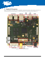
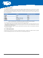
3.1.1 Front side Connectors
•
•
•
•
Triple Audio Jack (Microphone-In, Line-In and Headset-Out)
TV out (Composite)
SD-card socket
Power plug
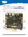
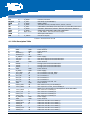
3.1.2 Rear side Connectors
•
•
•
•
•
4x USB A (host connector)
Ethernet
Mini USB AB (USB-OTG connector)
USB-B (device connector for terminal application)
HDMI Display output
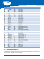
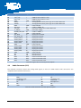
3.1.3 JTAG Connector
A standard ARM JTAG connector with 20 pins is available for debugging.
3.1.4 LED and Push Buttons
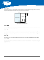
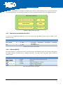
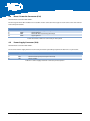
There are two push buttons and a single RGB-LED for user interaction. The RGB LED is connected to the MC18392
LED interface.
The push buttons have following functions:
•
•
S1: RESET
S3: Power On
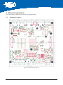
RGB-LED
PON RESET
Figure 3-2: LED and button positions
If the SBC is enclosed in a chassis, you may mount a light pipe (515-1011F from DIALIGHT) above the RGB-LED for
guiding the light to a front side panel.
SBC-i.MX51_HUM_V2.1.docx
14