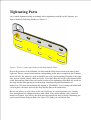
1
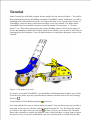
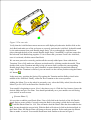
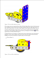
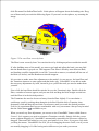
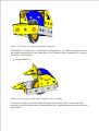
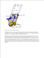
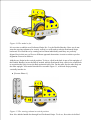
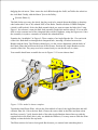
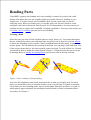
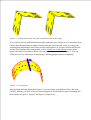
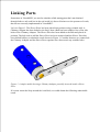
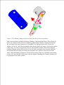
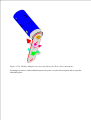
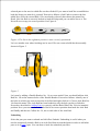
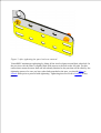
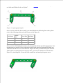
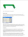
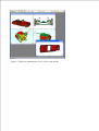
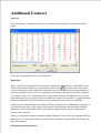
Introduction
VirtualMEC is a standalone 3D application that simulates building of real construction
models.
If you have just downloaded VirtualMEC from the public area of the VirtualMEC site, you
currently own the demo version of VirtualMEC.
It's highly recommended that you read and practice the Tutorial.
Tutorial
In this Tutorial you will build a simple Scooter model, the one shown in Figure 1. You will be
driven through the process of building a complete VirtualMEC model. Sometimes you will be
reminded to save the model built so far. You can do this only if you own the retail version of
VirtualMEC, since the demo version does not allow you to save models. The folder where
VirtualMEC has been installed contains several files named "Scooter phase 1", "Scooter
phase 2", etc. These files correspond to the various building phases of the Scooter model. If
you are not planning to follow the whole Tutorial in one session, you can refer to these files as
a starting point for each phase. You will find references to each phase during the course of the
Tutorial.
Figure 1. The model to be built.
If you have just started VirtualMEC, you should have a blank document window open. If this
is not the case, please close any open document windows and then open a new one selecting
File New .
Verify that Flat Colour Rendering button
is pressed.
Let's start with the first part we want to add to the model. You can choose any part you like to
start with; in this case we will start with the central Trunnion No. 126. The Parts Bar should
be visible on the right. If not you can click to show it. Now you can locate the Trunnion.
Please take a moment to explore the different views of the Parts Bar; you may want to choose
the type of view you are more comfortable with. You can also dock or undock the Parts Bar,
as you prefer, by dragging the top handle. Once you have selected the Trunnion, click
.
Now you have a Trunnion displayed in the document window of VirtualMEC. Let's spend
some time exploring the various ways to look at it using different points of view.
Verify that the Drag toolbar button is pressed. Just click and drag your mouse around the
model to see it from different points of view following your mouse movements. You can
zoom in
and out and you can pan the model using the scrollbars or clicking and
dragging using your mouse central button or mouse wheel. Once you have mastered the
various movements, end with the Trunnion in about the same position as in Figure 1.
Now it's time to add a Bolt to the Trunnion. Locate the correct hole nearest to you, where you
want to fix the Double Angle Strip No. 48a. Simply click in that hole. A Bolt No. 37b will
appear in the chosen hole. The Bolt is selected (red colour) so that you can operate on it. The
first thing to do is change its direction. While it is still selected, click on the Invert button .
Now you can add the Double Angle Strip No. 48a. Locate it in the Parts Bar and double-click
it. The Double Angle Strip adds itself to the selected Bolt, through the correct hole, but it is
incorrectly rotated. Click on it to select it, then press the Rotate 180° button . Now it should
be in the correct position. Re-select the Bolt and add a Nut to it by pressing the Add Nut
button .
Repeat the same procedure to add the other Double Angle Strip.
It's now time to add the rear axle and wheel. Select part Axle Rod No. 17 in the Parts Bar,
then locate the central hole of the left Double Angle Strip. Verify that the corresponding hole
of the other Double Angle Strip is NOT visible through the first hole, then click in the first
hole. The Axle Rod appears.
Double-click on the Axle Rod just added and a couple of movement arrows appear. You can
click and drag the red straight arrow to verify that the movements of the Rod are constrained
by the hole you clicked in. Leave the Rod in a half-way position with respect to the hole.
With the Axle Rod still selected (if it is not selected, click on it), add the following parts: a
Flat Trunnion No. 126a, a Spring Clip No. 35, a Pulley No. 22 which forms the wheel,
another Spring Clip and another Flat Trunnion. It doesn't matter for the moment if the
Trunnions are not correctly oriented, you can adjust their positions later. You should have
reached a result similar to the one in Figure 2.
[Scooter Phase 1]
Figure 2. The rear axle.
Verify that the Axle Rod movement arrows are still displayed (otherwise double-click on the
Axle Rod) and make use of the red arrow to correctly position the Axle Rod. It should extend
by the same amount from each Double Angle Strip. Yet even though the Axle Rod now
passes through the hole of the second Double Angle Strip, VirtualMEC is still not aware that
the hole and Axle Rod belong together. To let it know that, you must "hook" the Axle Rod;
once it is selected, click the menu Part Hook.
We can now proceed to correctly position all the recently added parts. Start with the last
Trunnion. First of all, make sure all parts are deselected by clicking outside the model. Then
double-click on the Trunnion and drag its big red arrow until it reaches the corresponding
Double Angle Strip. Since every part is hooked, no parts should go beyond their allowed
range. While the Trunnion is selected, you can rotate it to the correct position using the Rotate
90° button .
In the same way, position the Spring Clip against the Trunnion and the Pulley wheel in the
middle of the Axle Rod. Finally, rotate the first Trunnion to the correct position.
Adding the Motor Tyre to the wheel is extremely easy: select the Pulley wheel, then locate the
Motor Tyre No. 142c in the Parts Bar. Double-click it.
Your model is beginning to grow. Now’s the time to save it. Click the Save button, choose the
desired folder and give it a name. You should periodically save your models to avoid losing
your work if an error occurs.
[Scooter Phase 2]
It's now time to add the rear Plastic Plate. First of all click in the last hole of the left Double
Angle Strip to create a Bolt. Correctly orient the Bolt by inverting it (click the Invert button
). Add the Plastic Plate No. 194. You will notice that the Plastic Plate has been added to the
Bolt, but not through the correct hole. With the Bolt still selected, click in the desired hole in
the Plastic Plate; the Plastic Plate will jump to the new position. Select and rotate the Plastic
Plate to make it vertical. Your model should now look similar to the one in Figure 3.
Figure 3. The rear Plate about to be bent.
We can now proceed to bend the Plastic Plate. With the Plastic Plate selected, click the menu
Part Add Bend. Locate the bend arrow and drag it until the Plate has a right angle bend. You
may want to find a point of view that is more suitable for that operation. Remember that you
can always drag the image to find a better view. If you have trouble with your first bending,
don't worry. You can always undo your last actions, by clicking the Undo button , and try
again until your model looks like Figure 4.
If, during the process of bending, you inadvertently click outside the part, the bend selectors
disappear. To have them reappear, click the part to be bent, then click the menu Part Edit
Bending, then select the bend (the red sphere) and you are back again.
[Scooter Phase 3]
Figure 4. The rear Plate initially bent.
To begin with the bend is quite sharp; we need to soften the curve. With the Plate selected,
click the menu Part Soften Bend twice. Little spheres will appear about the bending axis. Drag
one of them until you reach the following figure. If you can’t see the spheres, try zooming the
image.
Figure 5. The rear Plate correctly bent.
The Plate is now correctly bent. You can deselect it by clicking anywhere outside the model.
If, after building more of the model, you want to go back and adjust the bend, you may find
that the Bend menu is greyed out. This happens if the Plate is fixed by more than one Bolt,
and bending would be impossible in real life. You need to remove (or unhook) all-but-one of
the Bolts (or Axles), and the Bend menu should reappear.
It's now time to make some fine adjustments to the model. As you can see, the bent Plate and
the Trunnions intersect at some points and that looks ugly. VirtualMEC is not able to make
the necessary adjustments by itself, instead it gives you all the tools you need to make them
yourself.
First of all, the bent Plate should be raised a bit over the Trunnions' edge. Double-click the
Plate, a number of arrows appear, and you can click and drag the little straight vertical one
until the Plate is in the desired position.
The Trunnions also need to be moved away from the Plate slightly. You can obtain a
satisfactory result by rocking them along the Axle Rod. Double-click a Trunnion, then
alternately click and drag the two little curved arrows until you reach the desired position.
Feel free to experiment until you are comfortable with every movement. Always keep in mind
that the Undo button is available to you.
When you need very fine adjustment, you can use a nice VirtualMEC feature called Remote
Control. Let's suppose you need to orientate a Trunnion vertically. Simply click the correct
arrow (without dragging it); VirtualMEC automatically remembers the last arrow clicked or
dragged. Then rotate the model so you get a good point of view. Now, if you press Ctrl while
you drag the mouse, VirtualMEC acts as if you were dragging the arrow itself, even if you are
not actually dragging it. It's like having an invisible arrow just under your mouse.
Once you have practiced Remote Control for a while, you will realize that finding the correct
position for any part that needs fine adjustment is easy and fast.
Now it's time to add the tail lights and obtain the result shown in Figure 6. Proceed as follows.
For the left light, select the Bolt on the left side of the body and click the Add Washer button
. Invert the Bolt and add a Nut to it. Now click in the corresponding holes in the right side;
invert the Bolt, add a Washer, re-invert the Bolt and add a Nut.
[Scooter Phase 4]
Figure 6. The rear part of the model.
We can now proceed with the saddle. We need a couple of Angle Brackets No. 12 to fix the
upper part of the Plate to the Trunnions. Click in one of the elongated holes on the edge of the
Plate and then add an Angle Bracket. You will want to bolt the elongated hole of the Angle
Bracket to the Plate, so click in that hole while the Bolt is selected and the Angle Bracket will
jump into place.
Now you can do a couple of things. Double-click the Angle Bracket and make use of the
correct arrow to slide it against the Trunnion. Again, to do so, find a comfortable point of
view and use Remote Control if you need it. The holes in the Angle Bracket and the Trunnion
are probably not in perfect alignment. You may need to slide the Angle Bracket a little bit
forward. To do so, double-click the Bolt (arrows appear), then click the Plate (new arrows
appear). Dragging these arrows will move the Bolt and everything attached to it, but NOT the
Plate you clicked. Try it until you are comfortable with this “double plus single” click feature.
(Remember to use the Undo button, if something goes wrong.)
Complete with Nuts and Bolts and do the same for the other side. Your model should now
look like the one shown in Figure 7.
Figure 7. The rear part of the model almost complete.
The saddle is a Trunnion No. 126 attached to a Fishplate No. 10, which is attached in turn to
the central elongated hole of the Plastic Plate. You should be able to complete it by yourself.
See Figure 8 for reference.
[Scooter Phase 5]
Figure 8. The rear part of the model complete with the saddle.
You are now ready to proceed with the front part of the model. Figure 9 shows the front
assembly with the Trunnion and a Perforated Strip No. 5 made transparent in order to see the
inner details.
Figure 9. The front part of the model.
A Fishplate No. 10 is lock-nutted to the front hole of the Trunnion. Click in the Trunnion's
front hole, add a Nut, add a Fishplate and finally add another Nut. The Fishplate needs to be
rotated by 90°. You should be able to do all this by yourself.
The other end of the Fishplate must now be bolted inside a Double Bracket No. 11, with
uprights pointing upward. Click in the front hole of the Fishplate to create a Bolt, then, with
the bolt still selected, add a Double Bracket. With the Bolt still selected, choose the correct
hole of the Double Bracket (the central one). The Double Bracket will jump into place, but is
still not correctly oriented. Select, invert and rotate the Double Bracket as necessary until it’s
facing the way you want. Invert the Bolt and add a Nut to it. Your model should now look like
Figure 10.
Figure 10. The model so far.
It's now time to add the two Perforated Strips No. 5 to the Double Bracket. Since we do not
want the steering column to be exactly vertical, we will need to rake the Perforated Strips
backward. We could do so by rotating each of them individually until they are perfectly
aligned, but in this case we'll use a different approach that makes it easier to achieve perfect
alignment. Proceed as follows.
Add the two Strips in the vertical position. To do so, click in the hole in one of the uprights of
the Double Bracket, invert the Bolt if needed, add the Perforated Strip, click in its second hole
to reposition the Strip, invert the Bolt again and add a Nut. Do the same for the other Strip on
the other upright. Your model should now resemble Figure 11, with both Strips pointing
vertically into the air.
[Scooter Phase 6]
Figure 11. The steering column in vertical position.
Now let's add the handle-bar through both Perforated Strips. To do so, first select Axle Rod
No. 16 in the Parts Bar, then click in the top hole of both Perforated Strips. Position the model
until you can see the second hole through the first one. Click in the hole and the axle appears.
If you have done everything correctly, you should be able to verify that this new handle-bar is
“hooked” to both the Strips. Please do so: double-click the Axle Rod and move the red arrow.
You shouldn't be able to unthread the handle-bar from the Strips.
It's almost time to rake the steering column. But first, let's say a few words about how
VirtualMEC handles movements of parts. If you double-click a part, VirtualMEC displays a
set of arrows that originate from one of the holes containing a Bolt or Axle Rod. For example,
if you double-click one of the Perforated Strips No. 5 that you have just added, VirtualMEC
will display a set of arrows around the hole containing the handle-bar. Try it. Now, if you
click the Bolt, the set of arrows will move there. Please note that you have NOT selected the
Bolt, you have simply changed the reference hole for turning operations. The Strip is still
selected. Now, what happens if you, say, drag the green arrow?
The Perforated Strip will rotate (in fact it's the selected part) with respect to the reference hole
(the red hole with the turning arrows). Other parts that the Bolt passes through will not turn,
and neither does the Bolt itself. But the handle-bar, because it is “hooked” to the Strip, will
follow the movement of the Strip, as will all other parts attached to the handle-bar: in
particular the second Strip and its Bolt, and, through them, every other part of the model,
since they are all connected. But we did not want the whole model to rotate around the
reference Bolt. But you should try it, just to see what happens. Then remember to press the
Undo button to go back to the previous situation.
So what do we have to do if we want to rotate the steering column, and nothing else? The
problem arises because the Bolt on the second Strip is “hooked”. If we remove this Bolt, the
problem no longer exists. Or, even better, we can “unhook” it. Unhooking stops the Bolt from
propagating the movement of the second Strip to the other parts of the model.
[NOTE] Beginning with release 1.2.4, VirtualMEC has the ability to automatically detect
Bolts and Axle Rods that are coaxial with the Bolt that is acting as a pivot. So unhooking
coaxial Bolts or Axle Rods is not needed anymore (VirtualMEC will do it for you). So, in this
particular case, unhooking is not necessary. Anyway it is still recommended that you practice
with unhooking, since in other situations that might be needed.
Once you have understood the logic just explained, the task is very simple. Select the Bolt you
want to unhook and click the Part Unhook menu. Now double-click the first Strip, click the
Bolt around which you want to rotate the steering column, and drag the green arrow. Only the
steering column rotates (consisting of the two Strips), and you can now incline it in the
desired position. Finally, don't forget to rehook the Bolt to the second Strip: select the Bolt
and click the Part Hook menu.
Let's proceed with the fork. The fork also needs to be inclined and we can repeat the above
procedure, but later. First, let's add the two Curved Strips to the handle-bar. Select the handlebar and add a Curved Strip Stepped No. 90a. It will appear next to one of the Strips on the
outer side. Since Axle Rods, unlike Bolts, do not have heads and stems, it's not easy to
anticipate where a new part will be added. You will get a hint if you double-click the Axle
Rod. The red arrow shows where the next part will be added. If you now invert the part ,
the red arrow will move to the opposite end, and when you add the second Curved Strip, it
will appear on the other side. Put simply, if a part attaches itself to the wrong end of a Rod,
you simply Invert
the Rod and try again.
Once you have added the two Curved Strips, deselect the handle-bar by clicking outside the
model and, with the aid of the Invert
and Rotate 90° buttons, position the fork as shown
in Figure 12. Then you can add a Spring Clip No. 35 at each side of the handle-bar to keep
things in place.
Figure 12. The fork in raised position.
We should now rotate the fork to the correct, downward position. We have several choices:
we can rotate each part individually until things line up correctly. Or we can add the wheel, in
order to "lock" the fork so that it moves as a unit. Or, we can use a little trick: we insert a
dummy Axle Rod through corresponding holes on either side of the fork. This also “locks”
the fork. Then we position the unit in the desired downward position, and can simply remove
the Axle Rod afterwards. This method is the easiest to implement.
Rotate the model so that the last holes of the fork arms are aligned and you can see through
both. Select an Axle Rod in the Parts Bar (any Rod will do, they are all long enough to go
through both holes). Click on the holes and the Rod is added. Now the fork assembly will
move as a whole. Double-click one of the arms, verify that the rotation arrows are displayed
around the handle-bar, and drag the green arrow to rotate the fork into the correct position.
The correct position is reached when the second hole from the top of each fork's arm
coincides with the second hole of the corresponding Strip No. 5. Now we can select the
dummy Axle Rod and delete it.
[Scooter Phase 7]
Moving on, let's do the front wheel. At the end of each fork arm you need to add a Fishplate
No. 10, using its elongated hole, and a Washer. See Figure 1 and Figure 9 for details. Once
again, we want to line up the Fishplates so that the Rod can be threaded through both.
To mount the wheel, proceed in a similar way as before. Select the Axle Rod part No. 18b in
the Parts Bar, then click on the hole of the nearest Fishplate. The Rod is added through both
Fishplates. (If you click on the hole of the farthest Fishplate, the Rod is added through the
farthest Fishplate only.) With the Rod still selected, double click on Pulley No. 22. It is added
between the Fishplates. (If not, you can correct the Rod and Pulley position using Ctrl+Drag.
Any time a Rod or Pulley needs to be moved beyond its natural stop, simply press Ctrl while
dragging the red arrow.) Now centre the Axle Rod through the forks, and centre the wheel on
the Axle Rod. Finally, add the Motor Tyre to the Pulley.
[Scooter Phase 8]
The little forks now carry the wheel, but they need to be rotated about their Bolts so that they
rake backwards. First of all, unhook ONE of the Bolts. Double-click the OTHER Fishplate
(which is still hooked). Select the Bolt around which you want to rotate the little fork. Using
Figure 1 for reference, rotate the little fork assembly (both forks and the wheel). You can also
slide it to the extreme end of the elongated holes on the Fishplates, using the big arrows. Once
the assembly is in place, remember to rehook the unhooked Bolt.
Examine the “headlights” in Figure 9. These consist of an Angle Bracket No. 12 at each side
of the fork. Bolt them on through their elongated hole, inserting a Washer between the
Bracket and the Strip. The Washers should give you the correct alignment with the holes of
the Plastic Plate that will form the front of the Scooter. Position the Angle Brackets on the
outside of the fork. They may need to be rotated, and you can do this one at a time.
Your model should now resemble the one in Figure 13. You are almost done!
Figure 13. The model is almost complete.
To add the front Plastic Plate, click in the forward hole of one of the Angle Brackets and add
a Plastic Plate No. 194 to the new Bolt. Choose the correct hole in the Plate and then orient
the Plate correctly. Verify that the hole of the other Angle Bracket almost lines up with the
required hole in the Plate (this is why we added the Washers). You may want to slide the Plate
slightly so that the holes line up better.
The Plate needs to be bent to look good. But because you cannot bend something that is
attached at several points, you cannot attach the second Bolt yet. You need to bend the Plate
before you attach it further. Start as for the rear Plate, and smoothen the bend until you are
satisfied.
Sometimes it helps to temporarily hide some parts of the model from view, so you can
concentrate on the part you are working with at the moment. In this case, you may want to
hide one side of the fork. First select a Perforated Strip No. 5, then, while holding down the
Shift key, select the corresponding Curved Strip. Both the Strips are now selected (red
outline). Click the menu Model Hide Selected Parts and they will disappear.
You can now bend the Plate carefully until it follows the curve of the visible fork, and finish
by clicking Model Unhide to see the whole model again.
Now, at last, you can add the second Bolt to the Plate with its Nut. Finally add the third Bolt
and a Washer to hold the windscreen; the windscreen is a Transparent Plastic Plate No. 193.
The model is now complete and should look like the one shown in Figure 1. Remember to
Save your work!
[Scooter Phase 9]
Finishing touches.
Let's add some finishing touches. Since you have built a Scooter model, it would be nice if it
could steer! VirtualMEC lets you identify a group of parts that can be moved together. These
groups are called units and they can perform simple movements, e.g. rotation and/or
translation. Let's proceed to define a Steering Unit.
Select the menu Model Unit. The Unit dialog box appears. Click New Unit, give the Unit a
name, for example Steering Assembly, and click OK. With the Unit dialog box still open,
identify the part of the model from which the Steering Assembly’s movement originates (the
Master part). This part is the Fishplate that is lock-nutted to the central Trunnion. Select it (if
you need to rotate the model to see it better, do so), and, once the Fishplate is selected, click
Set as Master.
Now you should identify the part around which the Fishplate will rotate (the Pivot part). This
part is the lock-nutted Bolt, so select the Bolt and click Set as Pivot. A set of arrows appears
around the pivot. They represent all the available movements for the Unit. To steer a Scooter
you need just one movement and you should disable all the others. Simply click once on each
unwanted arrow and it will turn grey, but do not click on the big green arrow, which is the
movement we want. If you make a mistake, or if the arrows disappear because you clicked
somewhere else, simply re-select the Bolt, click Set as Pivot, and start again.
Finally, you should tell VirtualMEC that the Steering Assembly (the Unit) consists of the
Fishplate (the Master part) and all the parts connected to it, but NOT the central Trunnion (the
Stop part). When you steer, this Trunnion (and all the parts connected to it) should not move –
That’s why it’s called the Stop part. So, select the Trunnion and click Set as Stop. To verify
that everything is correct before leaving the Unit dialog box, click Select Unit. You should see
that all the parts forming the Steering Unit are selected (red outline). Now click outside the
model and close the Unit dialog box.
Once you have created a Unit, you can recall it at any time to move it. Locate the Current Unit
combo box (it should be empty if nothing is selected), and click the pulldown button. You can
now select Steering Assembly, or whatever name you just gave the Unit, and a green arrow
should appear. Drag the green arrow to operate the steering. Click outside the model when
you are done.
[Scooter Complete]
Other features.
VirtualMEC provides another nice feature: the ability to save Viewpoints. Suppose you have
rotated the model so that you see the Scooter from the front. You can save this viewpoint and
recall it whenever you like. Proceed as follows: rotate the model until you have a nice front
view of the Scooter. Click the menu View Viewpoints, type a name for the view, for example
Front, then click Save. Later, when you want to recall that view, simply reopen the
Viewpoints dialog and choose the desired view from the list. If you name a viewpoint
"Default" (without quotes), the corresponding view will be automatically recalled when you
open a saved model and when you press the keyboard Home button.
Let's briefly explore some other VirtualMEC features.
Click the Semi-real Rendering button or choose Real Rendering from the View menu to
switch to more realistic views of your model with lights and shades.
Select Model Part List menu to have a complete List of Parts required to build your model.
You can also export the list to a text file.
If you wish to Save an Image, simply click on File Save Image As, and choose one of several
common formats (bmp, gif, etc). This is helpful if you want to illustrate building instructions.
This feature is available only in the retail version of VirtualMEC.
You can Playback the whole building process of your model from the beginning by choosing
View Player. A VCR-style console appears. By operating the console you can review all the
building stages of your model one step at a time or continuously in each direction. This
feature is available only in the retail version of VirtualMEC.
You can also Print the model. Select File Print or Print Preview. Printing doesn’t simply
transfer what you see on your monitor to paper: it re-renders the image at the resolution of the
printer. This can take time but the end result is well worth the wait. This feature is available
only in the retail version of VirtualMEC.
That's all for this Tutorial. You can now start to build your own models. For any issues not
covered in this tutorial and for a more detailed discussion of every VirtualMEC feature, please
consult the Help on Line.
Have fun with VirtualMEC!
Adding Parts
Adding the first Part
If the Parts Bar is not visible, click the Add Part button or choose View Parts Bar to show
it. The Parts Bar opens. Click on List, Details or Thumbnails to choose the list view you are
more comfortable with. Double-click on a part or click on it and the press to add it to the
model.
Adding a Bolt or Rod to a Hole
Clicking in a hole adds a Bolt to it. If you want to add another type of bolt or axle rod, select it
in the Parts Bar then click in the intended hole. If you want to bolt together more than one
hole, be sure to correctly align the model so that you click across all the intended holes. Let's
see an example. Figure 1a shows a Double Bracket No. 11. Through the front hole you can
see the rear hole, since they are aligned. If you add a Bolt No. 111 (right-click in the holes and
select it), that bolt will be added to both holes. You verify it by adding a Nut to the Bolt (click
the button). The Nut is inserted past the second hole (see Figure 1b).
Figure 1a
Figure 1b
Let's add instead the same Bolt to the same Double Bracket, but this time oriented as in Figure
2a.
Figure 2a
After having right-clicked in the front hole and chosen Bolt No. 111, the obtained result is
different than the previous one. The bolt seems to be hooked to both holes. but actually
VirtualMEC considers it bolted to only the front hole. You can verify it by adding a Nut to it.
Figure 2b shows the result.
Figure 2b
You usually choose the way to add bolts that best suits to you. You can then tell VirtualMEC
to consider all the holes aligned as bolted together by hooking the bolt.
Adding other parts.
Select the bolt or rod you want to add a part to, then click . The part you choose will be
added to the selected bolt or rod. If you want to change the bolted hole, with the bolt still
selected click in the desired hole. You will then probably want to move the part just added. To
add other parts you may want to invert the selected screw or axle.
Click
to add a Nut. Click
to add a Washer.
Adding special parts.
Adding certain parts is handled by VirtualMEC in a more specific way. If you want, for
example, add a Tyre to the corresponding Pulley, you should just add the Pulley, select it and
then double-click on a compatible tyre from the Parts Bar. It will be added to the pulley.
Selecting Parts
VirtualMEC makes use of part selections for many purposes (part movements, hiding, blocks,
etc.). It's very useful knowing the different ways to select parts.
To select a single part:
Simply click on the part you want to select.
To add other parts to a selection:
Press the Shift key and while it is pressed click on each other part you want to select.
To select an entire area of parts:
Verify that the following toolbar buttons are not pushed down , , . If one of them is
pushed down, click on it. Now you are in Select Area mode. If you click and drag the mouse
over your model you will select all the parts touched by the dragged rectangle area. Please
note that the parts eventually hidden by other parts will be selected too.
To extend a selection:
Click on the part or parts that form the base of the selection, then choose the Edit Extend
Selection menu. VirtualMEC will automatically select every part attached to the originally
selected parts. If you choose the same menu again, the selection will grow accordingly. You
can then fine-tune your selection by selecting other parts or deselecting some of the currently
selected parts.
To select all:
Choose Select All from the Edit menu.
To deselect a part:
Press the Shift key and while it is pressed click on each part you want to deselect.
To deselect all:
Click anywhere outside the model. If your model fills the whole window, you can select a
single part, then deselect it.
Moving Parts
Let's distinguish three different cases.
The part to move is not attached to any other part
This only happens if it is the first part of your model or if every previously attached bolt has
been deleted or unhooked.
Click once on the part to select it. You can now rotate it by right angles , or invert it .
Double-click on it to make a set of arrows appear. Drag each arrow to rotate or shift it in any
direction.
The part to move is attached in only one of its holes to a bolt or rod.
Click once on the part to select it. You can now rotate it by right angles , around the bolt
in its bolted hole. You can invert it only if it is the last part of its bolt. Double-click on it to
make a set of arrows appear. Drag each arrow to rotate or shift it along its bolt.
The part to move has more than one hole with bolts or rods.
Double-click on the part. A set of arrows appears identifying the bolt or rod around which
movements will occur. To change the bolt, click on another one. The arrows will move there.
You can now use movement buttons or the arrows to move the part. The part will move
relative to the last clicked bolt and every other part bolted with it will follow its movements.
Moving a bolt or an axle
Double-click the bolt or axle. A set of arrows appears. Use these arrows to slide or rotate the
bolt or axle. If the bolt is inserted in a hole of a part and you wish to move the bolt with
respect to that hole (e.g. you want to slide the bolt along an oblong hole), once the arrows are
shown, single-click the part to which the hole belongs. Now, by dragging the arrows, you will
be able to move the bolt with respect to that hole.
Sliding a part along an axle
When sliding a part along an axle or a bolt, VirtualMEC limits part movements with respect
to the other parts present on the axle itself. You can temporarily disable this check and let a
part sliding freely along the axle. To do so, press the Shift key during sliding.
Remote control.
Sometimes you would like to control a movement arrow without the need of keeping your
mouse on the arrow. This may happen when arrows are small and far from where you want to
drive their movements. This happens also when you move units or when you edit bends. To
use remote control, click on a movement arrow then move your mouse in a comfortable
position; now keep the Ctrl key pressed while dragging. The arrow will move just as if you
were dragging it.
Moving parts using the keyboard.
When accuracy is an issue, you can move a part using the keyboard. In this way you can rotate
or translate a part by precise amounts. When arrows are visible, click on one of the arrows,
then press + or - to move it at predefined steps. Hold down the Shift key to obtain smaller
steps. You can use the Steps dialog box to define step sizes of your choice (menu File Steps).
Deleting Parts
Select one or more parts then click the Del key.
Deleting a bolt will remove all the nuts attached to it.
Bending Parts
VirtualMEC supports part bending and, since bending is extensively used in real world
models, this means that you can virtually build every model. However, bending is not a
simple issue. You must exactly tell VirtualMEC how to bend a part until you reach a
satisfying result. When you bend a part, you usually apply one ore more bends to it and
configure each bend to obtain the desired result. It is recommended to do some practice on
bending in order to explore all VirtualMEC's bending capabilities. You may want to make use
of remote control or hiding parts not involved in bending.
Creating a Bend
Select the part you want to bend. Suitable parts are strips, plates, etc. You cannot bend parts
that are connected to other parts with more than one bolt or rod. In that case you can unhook
or delete the offending screws or bolts. Choose Add Bend from the Part menu. A bar and two
arrows appear. The bar indicates the position of the bend. You can drag it back and forth. One
of the arrows rotates the bar, the other actually creates the bend. Try with a Plate No. 188 and
you should be able to obtain the results shown if Figure 1. Simply deselect the part to accept
its bending. Refer to Modify an existing Bend if you need to edit an already set bend.
Figure 1. Some example of sharp bending.
You have thus obtained a sharp bend. Sometimes this is what you actually need, but other
times you would like to have a smoother bend or even a curved bend. To obtain a smoother
bend, while you are in bending mode, choose Soften Bend from the Part Menu. A couple of
small spheres appear alongside the bending bar and the bend is a little bit smoother than it
was before. See Figure 2.
Figure 2. A sharp bend on the left and a smoother bend on the right.
If you choose the Part Soften Bend menu again and again you will get an even smoother bend.
Choose Part Sharpen Bend to make it sharper. But this is not the only result you can get by
softening and sharpening a bend. Drag one the small spheres (if you have deselected the part
and the bend selectors have disappeared, refer to Modify an existing Bend to show them
again), the bend will extend to obtain a curved part as the one shown in Figure 3. You can
refine the curve by softening it or sharpening it and dragging the spheres adequately.
Figure 3. A curved part.
Starting from the bend obtained in Figure 3, you can obtain some further effects. Press the
Ctrl key, Shift key or Shift+Ctrl keys while dragging to obtain different types of bending like
those shown in Figure 4, Figure 5 and Figure 6 respectively.
Figure 4. Bending obtained by pressing the Ctrl key while dragging one of the small spheres.
Figure 5. Bending obtained by pressing the Shift key while dragging one of the small spheres.
A sort of spiral bending.
Figure 6. Bending obtained by pressing the Shift+Ctrl keys while dragging one of the small
spheres. A sort of parabolic bending.
You can combine all of the above ways in order to obtain the desired bending. You can also
add more than one bend to the same part. You should not "intersect" bends. If two or more
bends on the same part intersect each other, the visual result is that of a "broken" part.
Reposition one of the bends or delete it to obtain a correct bending.
Modifying an existing Bend
Select an already bent part and choose Edit Bending from the Part menu. One or more big
spheres appear to indicate existing bends. Click the one you need to modify. Now you can
proceed as illustrated above.
Removing Bends
You can remove the bend you are operating with, choosing the Part Remove Bend menu. You
can remove all the bends of a part, by selecting the part and choosing the Part Flatten menu.
You can reset a part to its default bending by choosing the Part Reset Bending menu.
Copying Bends
Sometimes you need to apply the same bending to several parts. Once you have bent one of
those parts in a satisfying way, select it and choose the Part Copy Bending menu. Now click
on the part you want to copy bending to. It will be bent accordingly. You can then modify its
bending if you need to. You can also invert its bending if you realize that bends have not been
copied the way you intended. Select it and choose the Part Invert Bending menu.
Linking Parts
Sometimes in VirtualMEC you need to simulate a link among parts that's not obtained
through bolts or axle rods but in the real world it is due to friction or to the presence of cords,
that are not currently implemented in VirtualMEC.
Let's see Figure 1. The Sleeve Piece has been placed into position using a simple trick. A
Chimney Adaptor has been bolted to the Strip, then a Bolt has been added to one of the side
holes of the Chimney Adaptor. The Sleeve Piece has been added to the Bolt and placed in
position. The bolt used to add the Sleeve Piece has been removed and the Sleeve Piece has
been shifted halfway to obtain the result shown in Figure 1. Consider that now we cannot bolt
the Chimney Adaptor and the Sleeve Piece together since there aren't any suitable holes.
Figure 1. A simple model showing a Chimney Adaptor partially inserted inside a Sleeve
Piece.
If we now rotate the Strip around the Axle Rod, we would obtain the following undesirable
result.
Figure 2. The Chimney Adaptor does not follow the Sleeve Piece movements.
That's because there's no link between the Chimney Adaptor and the Sleeve Piece. However,
in the real world, the Sleeve Piece would have followed the Chimney Adaptor movements.
We can impose the same behaviour in VirtualMEC by linking the two parts. Proceed as
follows: first of all, verify that the model is like the one shown in Figure 1 (before the rotation
of the Strip), if you have rotated the Strip you can Undo the rotation. Then select both the
Chimney Adaptor and the Sleeve Piece; to do so, click on one part, then keep the Shift key
pressed and click the other part. Both parts should be now selected. Select the Part Link
menu. The Link dialog box appears. Check the box stating "Part 163 will follow movements
of part 164" and click OK. From now on all movements regarding the Chimney Adaptor will
be propagated to the Sleeve Piece.
Figure 3. The Chimney Adaptor now correctly follows the Sleeve Piece movements.
To change or remove a link relation between two parts, re-select the two parts and re-open the
Link dialog box.
Hooking and Unhooking
Hooking
When you click in a hole to add, for example, a Bolt, VirtualMEC is aware that the hole
"belongs" to the Bolt. In fact, if you add another part to the Bolt, that part will be correctly
positioned past the already present part. In the same way a part added to a Bolt can be rotated
and moved relative to that Bolt. In conclusion VirtualMEC "knows" of all the holes "hooked"
to a Bolt.
"Hooking" is automatic when you add a bolt or a rod to a hole and when you add a part to a
selected bolt or axle rod. But in other situations you are responsible to hook or unhook a bolt
or axle rod by yourself. Let's see some cases.
Figure 1. A Perforated Strip with two Bolts.
Starting with the model shown in Figure 1, if we add another Perforate Strip to the selected
Bolt, we'll obtain the following result.
Figure 2. Another Perforated Strip added to the Bolt.
The selected Bolt has been automatically hooked to both the Strips. You can verify it by
adding a Nut to the Bolt. It will be added in the correct position, past the second Strip. But if
you select the second Bolt and add a Nut to it, you will notice a different behaviour. The Nut
in the rightmost position is not correctly positioned.
Figure 3. The Nut in the rightmost position is not correctly positioned.
That's because the second Bolt has not been automatically hooked to the second Strip.
VirtualMEC does not automatically hook holes other than the ones directly added to the
selected part or the ones in which the user has clicked. If you want to hook the second Bolt to
both the Strips you must do it yourself. Proceed as follows: click Undo to remove the last
added Nut, select the second Bolt, if it's not already selected, then choose the menu Part
Hook. Now the Bolt is correctly hooked to both the Strips and you can add a Nut to it. The
Nut will now occupy its correct position. See Figure 4.
Figure 4. The Nut in the rightmost position is now correctly positioned.
Let's see another case where hooking can be used. We now want to build the the assembly
shown in Figure 5.
Figure 5.
Let's start by adding a Double Bracket No. 11a to a new model. Now we should add an Axle
Rod No. 18a to the outmost holes of the Double Bracket. Proceed as follows: identify one of
the holes in which you want to insert the Axle Rod and right-click in it. Choose Axle Rod No.
18a from the menu. The Axle Rod has been hooked to only the hole you have clicked in.
Proceed as described in Adding Parts to correctly add the Bush Wheel No. 24 in its intended
position. Now you can translate the Axle Rod in its correct position then hook the Axle Rod
and finally add the two Collars No. 59, one to each side of the Axle Rod.
Unhooking
Select the part you want to unhook and click Part Unhook. Unhooking is useful when you
need to temporarily detach a Bolt or an Axle Rod from its attached parts in order to add other
parts to it or bend a part. You can then re-hook the unhooked part later.
You can visually identify all the parts that are hooked to a bolt or an axle rod. Select the bolt
or the axle rod and choose Select Hooked Parts from the Part menu.
Tightening Parts
Let's explain tightening using an example where tightening could be useful. Suppose you
want to build the following model (see Figure 1).
Figure 1. There is some space between the Strip and the Plate.
Due to the presence of the Fishplate, the Strip and the Plate do not touch each other at their
right end. There's a space between them corresponding to the space occupied by the Fishplate
at the left side. The model we want to build do not need a corresponding Fishplate at the right
side, instead it needs simply a Bolt and a Nut. If we add a Bolt and a Nut to the rightmost hole
of the Strip and the Plate in the real world, because of the tightening of the Bolt we would see
the Strip and the Plate getting in touch causing some imperceptible deformation of
themselves. This does not automatically happen in VirtualMEC. If you simply add a Bolt and
a Nut in place, the space between the Strip and the Plate will remain there.
But we can achieve a result closer to the real world one, in a semi-automatic way. Simply
click through both the rightmost holes to add a Bolt. Now, before adding a Nut, select the
menu Part Tighten. You will see the Plate moving towards the Strip, actually eliminating the
space between them along the Bolt (See Figure 2). Finally you can add the Nut.
Figure 2. After tightening the space has been removed.
VirtualMEC implements tightening by tilting all the involved parts around their other bolt. In
the previous case the Plate is slightly tilted with respect to the bolt on the left side. For this
reason there cannot be more than one bolt already attached to the part that will be tilted by the
tightening process. In case you have other bolts attached to the part, you should delete or
unhook them prior to proceed with tightening. Tightening does not involve bending of any
parts.
Hiding, Unhiding, and Transparent Parts
Sometimes you will find useful to hide some parts from your view, in order to concentrate on
the parts you are currently working at. To hide parts, simply select them and choose Model
Hide Selected Parts. If you instead want to hide all but a few parts, you can select the parts
you are interested to keep visible and choose Model Hide Unselected Parts.
To make all hidden parts appear again, choose Model Unhide.
You can also make parts transparent. This will results in the rendering of just the edges of
those parts, with the part itself transparent. Select the parts to make transparent and choose
Transparent from the Part menu. To make them visible again, select them and choose Part
Transparent. Since selecting a transparent part can be tricky (you must click on the visible
border of the part), you can select the area where the transparent parts are or even select all the
model. Now, when you choose the Part Transparent menu, the transparent parts will be made
visible again.
Units
VirtualMEC lets you identify some parts of your model that can be moved independently
from the rest of the model. For example you can move the boom of a crane or raise the arm of
a pull shovel. These parts are called units and you can associate to them simple movements
such as rotation or shifting.
To define a unit proceed as follows: choose Unit from the Model menu. The Unit dialog box
appears.
Click New Unit and assign a meaningful name to the unit. Usually a unit is made by some
parts that move with respect to a pivot. The part directly attached to the Pivot is called the
Master part. Now identify in the model the master part and select it, then click Set as Master.
Then select the pivot part and click Set as Pivot. As soon as you click Set as Pivot a set of
arrows appears indicating all the movements your unit can do. Usually you want to limit the
movements to just a rotational movement or a translational one. Click on the arrows you want
to disable, they will become greyed. At this point the unit is almost done. The master part will
move with respect to the pivot part and all the part attached to the master one will move
accordingly. The problem is that every part is directly or indirectly attached to the master part
resulting in the whole model moving when the master part moves. To avoid this, you should
identify one ore more Stop parts, that is parts that will not move together with all the parts
attached to them. Starting from the parts closer to the pivot (and eventually the pivot itself)
select one of them and click Set as Stop. Click Select Unit, all the parts forming the unit will
be selected and you can verify if you have reached your goal. If the unit is not what you
intended, select another part and click Set as Stop then recheck clicking Select Unit.
Once the unit has been defined, close the dialog. You can now select the unit or units you
have defined from the Current Unit combo box in the toolbar (the rightmost combo box).
Select the desired Unit, one or more arrows appear near the pivot of the selected unit. Drag
the desired arrow to move the unit. You can also use the Remote control feature.
To edit an already defined Unit, open the Unit dialog box and select the desired unit from the
combo box.
Blocks
Every model, especially big ones, is conceptually divided in blocks, somewhat independent
one from each other. For example a car model could be composed by the following blocks:
chassis, body, engine unit, etc. During the building of a model you usually work on a single
block at a time and it would be nice to have the possibility to hide all the other blocks.
VirtualMEC lets you do all this by defining and managing blocks.
In VirtualMEC every part of a model must belong to one block. This means that, even if you
have not defined any blocks till now, the parts forming your current model belong to a block.
This block is a default one created automatically by VirtualMEC and it is named Default. You
can verify this by looking at the drop-down list box on the left in the toolbar. It shows the
current block named Default. When you add a new part to a model, it will belong to the
current block. You may want to rename the Default block to a more meaningful name.
Defining a new block
Choose Blocks from the Model menu. The Blocks dialog box opens.
Type a name in the Current Block text box and click OK. A new block will be created and it
will become the current block.
Please note. If your model contains more than one block, every time you open it you will be
asked to choose the blocks to show.
Showing blocks
When you choose a block from the Current Block list box in the toolbar, that block will
become the current one and VirtualMEC will show only the parts belonging to that block.
This is useful when you want to switch from one block to another and working on each
individual block.
Sometimes you will want to show more than one block at a time. To do so, open the Blocks
dialog box and select all the desired blocks from the Visible Blocks list. You can make
multiple selections using the Ctrl key while clicking. Note that every time you click on a
block in the list, the Current Block box is consequently updated; so the last clicked block
should be the one that you want to be current.
To show all the blocks, click the Select All button in the Blocks dialog if it is open. Otherwise
choose Show all Blocks from the Model menu.
Moving parts to another block
Sometimes you may need to transfer some parts from their present blocks to another block.
This may happen if you have erroneously added parts to the unintended block or perhaps
because you want to split a big block in several smaller ones. Select the parts you want to
move to another block and the choose the menu Model Move to Block. Select one of the
blocks from the dialog box list or type a name for a new block. The selected parts will now
belong to that block.
Renaming a block
To rename a block, open the Block dialog box, select the block to be renamed, type a new
name in the Current Block text box then click OK.
Deleting a block
Open the Blocks dialog box and select a block, then click Delete. You can delete a block only
if it does not contain any part.
Engagements
VirtualMEC supports propagation of movements among parts composing a model. By
adhering to the following rules you will be able to instruct VirtualMEC to detect and
propagate movements among meshing gears or any other suitable parts.
Two kind of motion propagation are available: automatic and manual.
Automatic engagements occur when gears are involved. If, for example, two gears happen to
be side by side as in Figure 1, VirtualMEC automatically detects a possible mesh between
them, basing the detection on the kind of gears, their reciprocal positions and their teeth
counts. Apart from defining the appropriate units (see below), the user doesn't have to do
anything else in order to obtain an appropriate meshing of the gears, as long as the gears are
correctly positioned.
Manual engagements occur when parts, other than gears, are involved. Usually those parts
engage by means of chords, or chains or even different ways. Since VirtualMEC is not aware
of chords or chains, the user must supply the necessary information in order for motion to take
place.
Every part (gear, pulley, etc.) involved in an engagement must be part of a unit and must meet
at least one of the following requirements:
It must be one of the unit master parts.
or
It must be one of the parts directly attached to the unit pivot part.
In the example of Figure 1 (see below for unit definition), both conditions are met (just one
would suffice), since both the pinion and the gear are master parts of their respective units and
since both parts are directly attached to the pivot parts of their respective units.
Automatic engagements
As stated above, in order to have propagation of movements among gears or other parts, the
user must define units. Every axle or subassembly that can be involved in motion or that can
cause the motion of other subassembly must be defined as a unit. Please have a look to Figure
1, two units must be defined, one for each axle. The pinion unit will have the pinion as the
master part of the unit, the axle will be the pivot part and the strip the stop part. Similarly, the
gear unit will have the gear as the master part of the unit, the axle will be the pivot part and
the strip the stop part. In both units at least the rotational movement around the main axis (the
green big arrow) should be enabled. Once defined these two units, the user can move one unit
(by choosing it from the Unit combo box on the toolbar) and drag the intended arrow. The
whole mechanism will move accordingly.
Figure 1. A simple assembly with two meshing gears.
Manual engagements
Engagements can be set when motion propagation is desired among parts that do not directly
mesh and for which VirtualMEC cannot automatically determine any direct relation, for
example pulleys, sprocket gears, etc.
As for automatic engagements, the user must define the appropriate units (follow the
instructions above). Then the user must supply VirtualMEC with specific engagement
instructions. Let's consider Figure 3. Two pulleys have to be engaged together. Let's suppose
the appropriate units have already be defined. Now we have to engage them. Please proceed
as follows: select both pulleys (click on a pulley, then holding the Shift key, click on the other
one). Ensure that only the two pulleys are selected. Choose Engage from the Part menu. The
following dialog box opens:
Figure 2. The Engagement dialog box.
Let's familiarize with every aspect of the dialog box: the two parts involved are part No. 22
and part No. 19b (as you can see in the two sunken boxes). The direction in which
engagement will occur is <---> (both directions) meaning that a rotation of part No. 22 will
cause a rotation of part No. 19b and vice versa. In certain cases you would prefer to have only
a unidirectional engagement.
The two boxes marked Teeth / Diameter show the respective diameter of each pulley. These
boxes are automatically filled by VirtualMEC for some parts (pulleys, sprocket gears, etc.),
but you can edit their contents the way you like. Their values are used by VirtualMEC to
determine the ratio of the movements that will occur. In this case a value of 1 for part No. 22
and a value of 3 for part 19b mean that the big pulley is 3 times larger in diameter than the
other one and 3 turns of the little pulley will need to obtain 1 turn of the big one.
For each part, you can choose which type of movement will occur: rotational or translational.
In case of pulleys it will be a rotational movement for each part, but in other case you could
choose to have one or both parts involved in a translational movement. For example, a trolley
engaged by a pulley would have a translational movement; in this case the unit forming the
trolley should have enabled a linear movement in the intended direction. When a rotational
movement engages a translational one, you should set the value associated to the rotating part
equal to the diameter of the part itself and the value associated to the translating part equal to
1; VirtualMEC will compute a correct engagement ratio taking into account the circumference
of the rotating part.
Finally, you can set a reverse motion (by checking the Reverse box), meaning that a clockwise
rotation of one unit will cause a counter clockwise rotation of the other one. The Enable
checkbox lets you temporarily disable an engagement.
Going back to our example, if you leave all the proposed settings and click OK to close the
Engagement dialog box, you will obtain an engagement between the two pulleys as shown in
Figure 3. You can show/hide the red engagement line by choosing Engagements from the
View menu.
Figure 3. An engagement between pulleys. The red engagement line is shown.
If you need to edit or delete an already set engagement, re-select the two parts involved in the
intended engagement and choose Engage from the Part menu. A dialog box opens and you
can edit the engagement or even delete it.
Advanced
So far you have seen a straightforward example of engagement. However, engagements can
be used in more complex scenarios to achieve non trivial movements. As an example let's see
how a pantograph can be set up in VirtualMEC using units and engagements. A pantograph is
a simple base for more complex steering mechanisms.
Have a look at Figure 4. Once the pantograph is built and correctly set, you will be able to
move it obtaining the behaviour shown in Figure 5. First of all, build the model shown in
Figure 4; you should have practiced a bit with VirtualMEC before attempting to build this
model, if not, please read the help and practice the Tutorial first. For better realism you should
use lock-nutted bolts for the two joints.
Figure 4. A pantograph sample.
Once you have built the above model, you should define the following three units (please
refer to the following table and to the letters used in Figure 4):
Unit Name
Master
Parts
Pivot Part Stop Parts
1
B
A
2
D
C
C
3
F
E
D
Once you have defined the three units, you can proceed with the needed engagements. Two
engagements are needed. Select both parts B and D and open the Engagement dialog box.
Then check the Reverse box and click OK. Repeat the same procedure with parts D and F.
That's all! If everything has been correctly done, you can now obtain the result shown in
Figure 5 by choosing unit 1 from the Units combo box and moving the green arrow.
Figure 5. Motions applied to the pantograph.
Motion Panel.
Once you have defined the necessary units to control your model movements, you can
organize them into Motion Panel (see Figure 6). You can show or hide it by selecting menu
View Toolbars Motion or pressing Ctrl+M.
Figure 6. Motion Panel.
Simply select in each combo box the unit you want to control. For each one you can set its
relative speed by using the corresponding slider, the direction and the paused/active status by
using the corresponding buttons. The top slider and buttons control the overall speed,
direction and paused/active status of the whole model.
Conclusions.
Correctly handling an engagement can be a complex task. It is recommended to start
practicing with simple mechanisms and later proceed to more complex ones. Since an
incorrect setting of engagements or units could resolve in unexpected movements of parts, it
is highly recommended to backup the original model file prior to experiment with
engagements.
Even if you can enjoy creating complex mechanism using engagements in VirtualMEC,
please remember that only simple rotational and translational movements are currently
supported. More complex engagements could not be recreated, or at least not exactly as they
are in the real world. Sometimes you will be able to simulate complex mechanisms by
reaching a few compromises between the real one and the one simulated by VirtualMEC. In
general you should keep in mind that oscillatory or non linear movements are not supported.
Colours
VirtualMEC comes with a predefined colour scheme.
However, you can change the colour of each single part as well as create and save as many
custom colour schemes as you like. Colour schemes can then be applied to any model as a
whole.
Changing the colours of a few parts.
Select the intended part and choose the Part Colour menu. A Colour dialog opens showing on
the left the selected part name or every single element of a multicoloured part (such as a
wheel or a motor). If you selected two or more different parts, the left box will show
"Multiple selection". Click on any element in the left box to show its colour in the box on the
right. Click on that box to choose another colour. When you are done, the new colour will
appear in the box on the right. Repeat the process for any other element.
Now you can choose to Apply the colour change to just the selected part(s) or to apply it to all
the similar parts of the model (e.g. if you have selected a Strip No. 5 and have changed its
colour, all No. 5 parts of the model will change accordingly).
If you check the box "Set in Current Scheme", the chosen colour will be set in your current
scheme for that part or parts.
Using Colour Schemes
Choose Colour Scheme from the Model menu. A Colour Scheme dialog appears.
The dialog box shows all the parts available in the current version of VirtualMEC, each
associated with its colours.
To create a custom colour scheme, you should modify the colours of all intended parts. Select
or check the intended part or parts then click Colour to apply the desired colour to them.
Sometimes you will want to copy the colour of one part to other parts. In this case select the
part to be copied from and check all the parts to be copied to. Click Colour and then OK. The
correct colour will be applied to all the intended parts.
When you are satisfied with your scheme, you can save it giving it a name. Once you have
created several schemes, you can apply each of them to the current model, by opening the
Colour Scheme dialog box, selecting the desired scheme from the list and then clicking OK.
If you want that every new model you build be initially associated to a particular scheme,
select that scheme and click Set as Default.
Importing Colour Schemes
Since every model is associated to a colour scheme (either the default one or another one),
you can easily create new colour schemes from existing model files. Suppose you have a
model file created by another user and based on a colour scheme created by that user as well.
Simply load the file, open the Colour Scheme dialog box, the current scheme will be that
associated with the file just opened. Save the scheme giving it a name. Now you have a new
scheme for you.
Sets
VirtualMEC lets you define Sets. A Set is simply a way of organizing parts together, so that
you can concentrate on the parts needed for a particular model, while hiding all the parts you
are not interested in.
Example of sets are: the content of a set you own, the set of parts needed to build a particular
model, etc.
You define a Set by checking all the parts intended to form that set. Then you have two
choices: you can press OK and the set you have just defined becomes your current set or you
can give it a name, choosing Save As and typing a meaningful name. In both cases you will
see its parts shown in the Parts Bar. If you have given it a name, it will be displayed at the
bottom of the Parts Bar.
You can check all and only the parts used in your current model by clicking Check Used.
Sets are saved along with models. So if you load a model file created by another user and you
want to add its set to your list of custom sets, simply open the Sets dialog box and save it.
If you "set as default" one of your named Sets, it will be the current set when you start a new
model.
Rendering
VirtualMEC supports several ways of graphics rendering. For model building, Flat Colour
Rendering is probably the most useful. Parts are rendered in plain colours for a clear and
sharp view and redrawing is quite fast.
Switch to Semi-real rendering
to see shades with sharp, marked borders.
For a more realistic rendering with colour shades, you can switch to View Real Rendering.
You can choose White Rendering from the View menu to have a black and white rendering of
your model, suitable for black and white printing.
If you experience delays during rendering while you drag your model around (probably
because the model is really big and/or your computer is not very fast), you can press the Fast
drawing button . It will speed up rendering during movements, since it uses a wireframe
rendering of the model.
Views
You have probably realized that one of the nicest features of VirtualMEC is that it lets you
watch a model from any point of view.
Zooming
Click the toolbar buttons
and to zoom in and out respectively or use the slider situated
between them. If your mouse has a wheel, you can use it to zoom as well. Click
and then
drag a rectangle on the screen to zoom in that area.
Panning
Use the scroll bars to pan the scene horizontally and vertically. If your mouse has a wheel or a
central button you can use it to pan as well.
Click the Centre button
centre of the window.
and then click in a point of the model to move that point in the
Rotating
Click the Drag button and then click and drag the mouse on the scene to rotate it
accordingly. The scene will be rotated around the centre of the model. This is usually the
centre of the first part you added to the model. Most of the times, especially when dealing
with big models, you will want to rotate the scene around a centre that is not the centre of the
model. Simply select the part you want to rotate around and that part will become the rotation
centre.
Viewpoints
Every time you change your point of view (by rotating or zooming the scene, for example)
VirtualMEC automatically stores its associated viewpoint. This means you can recall a
previous viewpoint and then eventually go back to the current one. Press to move to a
previous viewpoint (you can do it several times), press
to go to the most recent ones.
You can also save named viewpoint, so that you can recall them by name. One you have a
satisfying viewpoint, choose Viewpoint from the View menu. The Viewpoints dialog box
appears. Type a name (e.g. Front, Rear, Underneath, etc.) and click Save. If you want to save a
new viewpoint under an existing name, select that name from the list, then click it again to
enable the Save button, then, if you press Save, you will replace the old viewpoint with the
current one.
To recall a saved viewpoint, open the Viewpoints dialog box, select the desired viewpoint and
click OK.
If you name a viewpoint "Default" (without quotes), you can recall it by simply pressing the
Home key. It will also be the current viewpoint when you load a model file.
Multiple views
VirtualMEC supports working with multiple models at a time. This means that you can open
more than one model each in its own window.
VirtualMEC supports also multiple views of the same model. You can open a new window
for the same model by choosing New Window from the Window menu. Or you can split a
single window in two or four panes showing different views of the same model. To split a
window click and drag any of the split bars located near at the left or the top of the
corresponding scroll bar.
You can operate on any view as well apply different styles of rendering, blocks shown, etc. to
each view.
Figure 1. Different simultaneous views of the same model.
Player
At any time you can playback the whole building process of a model. Select Model Player to
show the Player bar. It is a familiar VCR-style console.
Press
to watch a complete animation. You will see your model growing one part at a time
from the first part to the last one. Press to watch it from the end to the beginning. You can
press
at any time to stop the animation. You can advance or go back one "frame" at a time
by pressing or respectively.
Press
to "rewind" the animation to the beginning (no parts will show) or to go directly
to the end (the actual state of the model). Pressing will also exit Player mode.
During playback you can look at the rightmost pane of the Status bar. It will show an
indication in the form xxx/yyy. For example, if it shows 100/500, it means that your model
contains 500 parts and you are currently watching the first 100 parts.
While not in Player mode, the rightmost pane will show just 500, meaning that your model
contains 500 parts and you are not in Player mode.
Using the slider you can quickly move to the desired point.
You can temporarily pause the animation by pressing
animation.
. Pressing it again will resume the
Animation normally advances one part at a time (e.g. each new "frame" will show a part more
than the previous one, if you are playing forward). During an animation or when the
animation is paused, you can press P to increase the number of new parts shown at each
frame. Press Shift+P to decrease the number. Pressing , or will reset the rate to one
part at a time.
You can save the current point by pressing
pressing .
. Later you can go to the last saved point by
Please note.
It may happen that you stop in the middle of an animation and realize that you need to add a
new part to the model. If you actually add a new part you will not see it. Why? Let's suppose
you are watching the first 100 parts of a model made of 500 parts. If you add a new part it will
become the 501st part, but you are still watching the first 100 parts!
Thus, to avoid confusion, it is recommended to exit Player mode (by pressing ) each time
you need to modify your model. As said before, looking at the status bar's rightmost pane is
an easy way to know if you are in Player mode or not.
Printing
Select File Print to print the model shown in the active VirtualMEC window. You may want
to first try Print Preview until you are satisfied with what will be actually printed. You may
want to switch between Portrait and Landscape Orientation prior to actually print.
For better results, printing is made at printer resolution, that is usually higher than screen
resolution. This can lead to a time consuming process.
Additional Features
Part List
You can display a complete list of parts of a model by choosing Part List from the Model
menu.
You can also export the list in a text format file.
Reposition
When you start a new model, the first part you add will be considered by VirtualMEC as the
centre of the model. Whenever you rotate the model (using ) it will be rotate around that
centre. Sometimes it may happen that, during the course of building, the first part changes its
position (possibly because you have rotated it or inverted it with respect to a bolt) or simply
your model "grows" in a certain direction. In both cases what you consider the very centre of
the model may now be far from what was initially the centre of the model. It is quite annoying
rotating a model and seeing it rotates around a centre that is not what you would like.
In this case you can reposition the model (actually re-centring it) by identifying a part that you
consider the most close to the centre of the model. Select that part and then choose Model
Reposition. The whole model will be repositioned around that part and the rotation will
become more "natural".
When you reposition a model apparently nothing happens. You will not see anything different
than before. You can realize that the model has been actually repositioned by deselecting any
part and rotating it.
Merging and pasting models
You can merge your current model with an existing saved one or you can paste a previously
cut or copied assembly.
Choose Merge With from the File menu and select the model you like or choose Paste from
the Edit menu. The merged/pasted model will appear under your mouse; moving your mouse
you will be able to place it in a convenient position. Click any button to drop it. Now, you can
link the original model and the merged one. Usually you select a bolt of one model and click
in a hole of the other one. The two models will link together.
Please note. The merged model will move to the new position as a whole. Every parts forming
the merged model will correctly move to the desired position only if they have been properly
hooked or linked. Prior to merge a model, verify that all its parts are correctly hooked and/or
linked.
Saving images
You can save the image currently shown in any VirtualMEC's window by choosing File Save
Image As. You can choose your preferred image file format.
Springs
Springs support compression (all) and torsion (part No. 43). Select the spring and look at the
status bar for instructions on how to handle it.