1
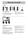
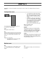
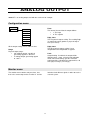
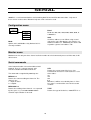
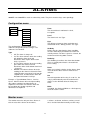
USER MANUAL
5.8.2008 V1.3
Setpoint unit
2022Setp
1
INTRODUCTION
2022Setp is a special edition of Nokeval 2022
multi-input indicator. It is available in wall-mounted
“2800” enclosure or in a 1/8 DIN panel enclosure.
Normally it is equipped with an analog output
card, and possibly with serial communications
card, an alarm relay card, or another analog
output card. There is always one mA/V process
input with transmitter supply 24 V 250 mA.
Configuration can be fully performed either with
the front panel buttons or using serial
communications and Mekuwin PC software. The
latter option however requires a serial
communications card.
SPECIFICATIONS
Input card
Serial communications card
Galvanic isolation
Update rate
Yes
6 / sec typ
mA input
Input resistance
Physical range
Calibr accuracy
Linearity
Tempco
Transmitter supply
50 ohms
0..24 mA
± 8 µA
± 3 µA
± 100 ppm/°C
24 V ±20% 260 mA
V input
Input resistance
Physical range
Calibr accuracy
Linearity
Tempco
1.1 Mohms
0..12 V
± 5 mV
± 2 mV
± 100 ppm/°C
Ports
Galvanic isolation
Protocol
Baud rates
Response
Alarm relays
Configuration
Ratings
Analog output card
General
Galvanic isolation
Power supply
Yes (shared with serial
communication and
another output card)
mA output
Max range
Calibr accuracy
Linearity
Max load
0..20.8 mA typ
± 8 uA
± 4 uA
12 V (600 ohm)
V output
Max range
Calibr accuracy
Max load
0..10.5 V typ
± 5 mV
3 kohm
RS-232 or RS-485
Yes (shared with analog
outputs)
Nokeval SCL
300..19200 bit/s
200 ms max
One or two two-relay
cards (2000REL2) or
one three-relay card
(2000REL3)
250 VAC 2 A
non-inductive load
85-260 VAC or
12-32 VDC
Ordering
The full ordering code for a panel indicator with
one analog output and 85-260V supply is:
2022SETP-OUT-230VAC
To add a serial card, include -RS- in the chain. To
have relay cards, include -REL2- or -REL3-. Only
two option cards can be included!
And for a wall-mounted indicator precede with
2800-:
2800-2022SETP-…
2
INSTALLATION
Connectors
6
5
4
Com
3
3
TxD
2
2
Com
1
1
RxD
+V
V
6
A
Com
5
B
mA
4
REL3
REL2
RS-485
SERIAL
OUT
+24V
2W
+mA
!
6
RS-232
2022Setp
6
5
4
3
2
1
3
5
1
1
5
4
4
2
6
2
3
2
1
1
Power
supply
2
+L
3
-N
7 8 9
connectors 3 and 4 must always be linked
together!
Slot A = 2022Setp input card
Slot B = Analog output (or other option card)
Slot C = The second option card
If a pre-fuse is used in 230V power supply
connection, it should be at least T500mA. The
indicator has an internal pre-fuse. The polarity of
the power supply has no matter.
An active milliamp signal is connected to A5+ and
A3-. A two-wire transmitter may be connected to
A6+ and A5-. Voltage signal is brought to
terminals A1+ and A3-. Note that slot A
Jumpers
on off
2000-RS
Term
Fs
RS232
RS485
RS485
(Factory setting) Last unit on bus
on
on
on
off
off
off
Term
Fs
Term
Fs
Term
Fs
Configuration
match those in MekuWin. The settings are
described in chapter Settings / Serial
communications, and the MekuWin program has a
manual of its own.
Using front panel
The indicator can be fully configured using the
front panel keys. The configuration settings are
explained in chapter Settings, and using the front
panel is described in chapter User interface.
The Slot parameter in Mekuwin is used to select
which “slot” or card is configured. 0=Master
(setpoint), 1=slot A (input), 2=slot B (output),
3=slot C.
The indicator keeps measuring and updating the
alarms, but the serial output is not available.
The indicator keeps measuring during the
configuration, and the MekuWin monitor function
can be used to see the current readings.
Using configuration software
MekuWin program (free from Nokeval web site) is
used to configure the device using RS-232 or RS485 communication. If connection fails, check the
communications settings using front panel keys to
3
OPERATION
Data flow
Internal
bus
Display
135000
Blink
Serial
Setpoint
Ch 8
Ana output
Scaling
Input
Ch 1
Alarms
The mA or V input is first measured. This
information is converted to a scaled reading (in
any engineering units) using two freely selectable
sample points, e.g. 4.112 mA corresponds to 0
bar and 16.501 mA corresponds to 6 bar. This is
set up in slot A configuration menu. The reading is
put available on internal channel 1, to be available
for the outputs and the display.
There is one user-adjustable setpoint, that can be
changed using the front panel buttons ^ and v.
This setpoint is available on channel 8.
The alarms and analog output(s) can be taken
from channel 1 (input) or channel 8 (setpoint).
4
USER INTERFACE
Front panel
Normal state
In normal state, this device displays the current
measurement reading continuously functioning as
an indicator.
•
The display can be set to three different modes.
They are:
• Normal. The display consists of a
channel number and a reading. The
channel can be selected with ^v keys.
Channels: 1=input, 8=setpoint.
• Setpoint. The display is always showing
the adjustable setpoint (channel 8), and it
can be adjusted using buttons ^ and v.
MeaSet. The display shows normally the
input (channel 1), but can be requested to
show the setpoint by pressing ^ or v for
the time specified in the settings. The
setpoint can then be adjusted. The
display is returned to input display when
no buttons is pressed for a while.
The indicator LEDs A1-A4 show the status of the
alarms. The Conf LED is lit when in configuration
state. Additionally, M1 blinks when the setpoint is
being adjusted.
Configuration state
Press * and ^ simultaneously two seconds to
enter configuration state. First, select the slot to
be configurated. The options are Master, Slot A,
Slot B, and Slot C. Proceed with >. If configuration
password is set, you will now need to enter it
(Cod.0 displayed). In case the password is not
known, switch the power off, hold * and > keys
pressed and switch the power on again.
5
*+^
Slot
Master
Conf
>
Submenu1
Slot A
*
Slot B
Slot C
Submenu2
^
v
Submenu3
...
>
>
>
>
*
^
v
Submenu1
Item1
> *
^v>
Editing
...
...
...
...
*
*
...
Save
Undo
To set a password, push ^ to select Set (means
password will be used), then push > to enter the
new password. Cod.0 is shown. The password is
a sequence of six keypresses using all the four
keys. Enter the same password twice; if they
match, Set is shown again and you can exit with
*. If they didn’t match, Off is shown. Redo from
start. To disable a password, push v to select Off
and exit with *.
The main level of the configuration menu is
shown. You can select among menu items using
^v keys. To edit the setting, push > to start
editing, and * to get back to the menu. How to
edit, see chapter Editing.
Most data types are edited simply with ^v keys,
finally exiting with * key.
Floating point values, such as scaling and
lopass filter, are edited with ^v> keys: select digit
to edit (blinks) with > and change it with ^v.
When the decimal point is blinking, it can be
moved with ^v. The first digit can be replaced
with a minus sign.
When all settings are done, exit from the menu
with * key. Two options are shown: Save to keep
the settings made, and Undo, to discard all the
changes. Select Save or Undo and push *.
Finally, exit from the slot selection by third * (or
select another slot with ^v and so on).
Monitor state and simulation
Monitor function can be used while
troubleshooting to view some internal values of
the indicator. It can be accessed either from the
front panel or using the configuration software.
update them. Then they may be changed by the
user to test the system. How to lock in Mekuwin,
see its manual. To lock using the front panel, do
as follows:
1. Enter the monitoring state as described
and the slot you want to.
2. Select the item to be locked using ^v
buttons. Do not push > yet.
3. Press and hold > button. Then push ^
also. Release them both.
4. Now you can enter a new value to
simulate/test something.
5. Exit with *.
To return to normal operation, do the same, but
while holding >, push v.
Monitor mode is entered in the normal state by
pressing * and v together. Select slot with ^v
and push > to enter. The monitored item can be
selected with ^v. To return to slot selection, push
*. To return to normal state, push * once more.
Objects to monitor are described in sections of
each card.
Some monitor items have a possibility to be
locked, so that the indicator does not anymore
6
MASTER / SETPOINT
The master is responsible of the user interface (display and buttons) and of the setpoint. To set up an analog
output following the setpoint, see chapter Analog output.
Configuration menu
•
Conf
Gen
Gen
Bright
Setpoint
CfCode
•
•
Setpoint
Mode
Normal: Displaying channel number +
reading.
Setpoint: Displaying the setpoint all the
time.
MeaSet: Displaying the input reading or
the setpoint.
Setpoint\Startup
Setpoint value source after power-up.
• Preset: The initial setpoint value is set in
the next menu item.
• Last: The setpoint is preserved during
power-off.
Startup
Preset
Min
Max
Dec
Delay
Setpoint\Preset
Setpoint value after power-up. This item is hidden
if Startup is set to Last.
The configuration menu of the master is divided in
two sections, Gen (general) and Setpoint settings.
Setpoint\Min, Setpoint\Max
These define the range where the setpoint can be
adjusted.
Gen\Bright
Display brightness 1-15. Default value 7.
Gen\CfCode
Password for all the configuration settings. Will
apply for the other cards too. If the password is
set and forgotten, turn the power off, hold * and >
pressed and switch power on. To set the
password, select Set, push >, and enter the same
password twice. If Set is displayed again, you can
exit with *. The password consists of six
keypresses using all the buttons.
Setpoint\Dec
Number of digits after the decimal point for the
setpoint. Defines also the smallest setpoint step.
Setpoint\Delay
This defines how long ^ or v key has to be
pressed until the setpoint adjustment mode is
entered. The time is given in seconds (max 12).
Setpoint\Mode
Operation mode, as described in chapter User
interface, Normal mode.
Monitor menu
The monitor menu has only one item, Mainch,
which tells which internal channel is currently
being displayed.
7
INPUT
2022SETP is an input card capable of measuring one mA or V signal. The reading will be put on internal
channel 1.
Configuration menu
•
Conf
In
In
Input
Dec
•
Pts
Mea1
Sca1
Mea2
Sca2
1: One point offset scaling. Input signal
Mea1 will be converted to scaled reading
Sca1 using appropriate offset. In other
words, Sca1-Mea1 is added to the input
reading.
2: Two point scaling. Input signal Mea1 (in
mA or V) is converted to scaled reading
Sca1 (in any engineering units) and Mea2
is converted to Sca2. Linear interpolation
and extrapolation is applied. E.g. to
convert 4-20 mA to 0-100(%), set
Mea1=4, Sca1=0, Mea2=20, Sca2=100.
MeaMin
Mea1, Sca1, Mea2, Sca2
Scaling points, see Pts.
Lopass
The configuration menu has one submenu, In,
that contains the input settings.
MeaMin
Input signals (in mA or V) less than this will be
regarded as a fault. Dashes are displayed and
alarm relays pulled. If you have 4-20 mA input,
you might use MeaMin=3.5 (mA). To disable, set
to some large negative value, e.g. –10000.
Input
Input signal selection mA or V.
Dec
Number of digits to display after the decimal point.
Can also be set negative to have fixed zeros. E.g.
if Dec=-2, the display will be rounded to 0, 100,
200, etc.
Lopass
Digital lowpass filter for input. Functions like a RC
circuit damping variations in the reading. Set the
time constant in seconds. Recommended value 1.
To disable filtering, set to 0.
Pts
Number of scaling points.
• 0: No input scaling. The input signal will
be displayed as is, in mA or V.
Monitor menu
Mea
The input reading with no scaling applied, in mA
or V. Can be locked to test the scaling and the
outputs.
Sca
The scaled input reading. Can be locked to test
the outputs.
8
ANALOG OUTPUT
2000OUT is an analog output card with one active mA or V output.
Configuration menu
Conf
Out
From
The internal channel that the output follows:
• 1: The input
• 8: The setpoint
Out
Range
From
Rdg1
Rdg1, Out1
The first point in output scaling. The reading Rdg1
(in engineering units) produces physical output
Out1 (in mA or V).
Out1
Rdg2
Out2
Limit
All the output settings are in submenu Out.
Rdg2, Out2
The other point in output scaling. Linear
interpolation and extrapolation is applied.
Range
Physical output range:
• mA: milliamp output, capable of
generating approx 0…20.8 mA.
• V: voltage output, generating approx
0…10.5 V.
Limit
Output limiting. If enabled, the output will be
limited to Out1…Out2, except in fault indication
mode, when it will always give the maximum
output possible. If disabled, the output will use all
of its physical range (see Range).
Monitor menu
The monitor menu contains only one item, Out,
that is the current output value in mA or V. Can be
locked to feed different signals in order to test the
external system.
9
SERIAL
2000RS is a serial communications card containing both RS-232 and RS-485 connections. Only one of
these can be used at a time. Moreover only one serial card can be used.
Configuration menu
Conf
Ser
Baud
Baud rate 300, 600, 1200, 2400, 4800, 9600, or
19200 bits/s.
Ser
Mode
Baud
Addr
Addr
Serial bus address 0-123. When using several
units on the same RS-485 bus, they must be set
to different addresses. Additionally, this device will
respond in “general call” address 126.
Mode
Options SCL and Modbus. Only Nokeval SCL is
currently available.
Monitor menu
Monitor menu has only one item, Count. It tells the number of serial commands processed. After 255, it will
roll over to 0.
Serial commands
Serial communications is based on Nokeval SCL
protocol. There is a separate manual “SCL
manual” available from Nokeval web site.
KEY
Returns the current state of the keys. One
hexadecimal character is returned, that is a sum
of the codes:
^1
v2
*4
>8
Moreover, it will be succeeded by letter “L” if the
key status is remained the same for at least 0.5
seconds.
The commands recognized by 2022Setp are:
MEA CH 1 ?
Returns the current reading on channel 2. The
channels are:
1 = input on slot A
8 = setpoint
MEA SCAN 1 3
Returns the readings from channels 1-3 separated
by one space, e.g. “101.000 0.00000 79800.”.
Scientific representation is not used.
TYPE
Returns the type of the device, “2022SETP V1.3”.
10
ALARMS
2000REL2 and 2000REL3 cards are alarm/relay cards. They have 2 and 3 relays correspondingly.
Configuration menu
Conf
Alm1
Alm2
Alm3
From
The channel that is monitored. 1=level,
8=setpoint.
Alm1
Type
From
Level
Level
The alarm level. See Type.
Hyst
Delay
Hyst
The difference between alarm activation and
deactivation levels. Always positive. See Type.
NC
Blink
The configuration menu has two or three
submenus, depending on the card type. The
submenus are identical.
ActDelay
Defines the time how long the alarm condition
must be continuously true before the alarm will
actually activate. The time is given in seconds, the
maximum value being 4295 seconds.
Type
•
•
•
•
Off: The alarm is always off.
Lo: The alarm activates when the reading
falls below the alarm level and
deactivates when it goes above alarm
level + hysteresis.
Hi: The alarm activates when the reading
goes above the alarm level and
deactivates when it falls below alarm level
– hysteresis.
Window: The alarm activates when the
reading (on the channel selected in From
setting) deviates more than Level from the
setpoint value, and deactivates when the
deviation falls below Level-Hyst.
DeaDelay
Like ActDelay, but affects the alarm deactivation.
This is used only when Auto is selected in the
Reset setting.
Reset
Alarm reset switch selection. Select always Auto,
since this device does not have manual reset
switches.
NC
Invert the operation of the relay. If set to Yes, the
relay is pulled normally and released when the
alarm is active. Will not affect the front panel
LEDs.
Example 1: Type=Window, From=1, Level=5,
Hyst=1. Alarm activates when the input reading
goes above setpoint+5 and deactivates at
setpoint+4. The alarm also activates when the
input reading goes below setpoint-5 and
deactivates at setpoint-4.
Blink
If enabled, the display will blink on 1 Hz frequency
when this alarm is active.
Monitor menu
The monitor menu has only one item, Alarms. It
tells the state of the alarms. 0=no alarms,
1=alarm1, 2=alarm2, 4=alarm3, and any sum of
these. Can be locked to manually test the relays.
11
Yrittäjäkatu 12
37100 Nokia
Finland
Tel +358 3 3424800
Fax +358 3 3422066
www.nokeval.com
12