1
INSTALLATION
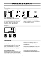
Connectors
6
5
4
Com
3
3
TxD
2
2
Com
1
1
RxD
+V
V
6
A
Com
5
B
mA
4
REL3
REL2
RS-485
SERIAL
OUT
+24V
2W
+mA
!
6
RS-232
2022Setp
6
5
4
3
2
1
3
5
1
1
5
4
4
2
6
2
3
2
1
1
Power
supply
2
+L
3
-N
7 8 9
connectors 3 and 4 must always be linked
together!
Slot A = 2022Setp input card
Slot B = Analog output (or other option card)
Slot C = The second option card
If a pre-fuse is used in 230V power supply
connection, it should be at least T500mA. The
indicator has an internal pre-fuse. The polarity of
the power supply has no matter.
An active milliamp signal is connected to A5+ and
A3-. A two-wire transmitter may be connected to
A6+ and A5-. Voltage signal is brought to
terminals A1+ and A3-. Note that slot A
Jumpers
on off
2000-RS
Term
Fs
RS232
RS485
RS485
(Factory setting) Last unit on bus
on
on
on
off
off
off
Term
Fs
Term
Fs
Term
Fs
Configuration
match those in MekuWin. The settings are
described in chapter Settings / Serial
communications, and the MekuWin program has a
manual of its own.
Using front panel
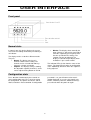
The indicator can be fully configured using the
front panel keys. The configuration settings are
explained in chapter Settings, and using the front
panel is described in chapter User interface.
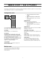
The Slot parameter in Mekuwin is used to select
which “slot” or card is configured. 0=Master
(setpoint), 1=slot A (input), 2=slot B (output),
3=slot C.
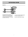
The indicator keeps measuring and updating the
alarms, but the serial output is not available.
The indicator keeps measuring during the
configuration, and the MekuWin monitor function
can be used to see the current readings.
Using configuration software
MekuWin program (free from Nokeval web site) is
used to configure the device using RS-232 or RS485 communication. If connection fails, check the
communications settings using front panel keys to
3