1
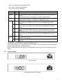
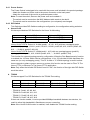
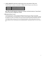
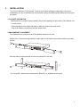
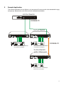
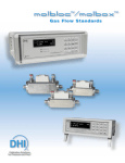
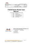
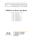
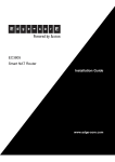
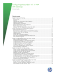
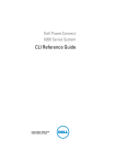
539
USER’S MANUAL
16-Port 10/100Mbps Fast Ethernet Switch
16-Port 10/100Mbps Fast Ethernet Switch with 1 Fiber port
USER'S GUIDE
TABLE OF CONTENTS
1
UNPACKING INFORMATION............................................... 3
2
PRODUCT INTRODUCTION................................................ 4
2.1
Models ............................................................................................. 4
2.2
KEY FEATURES ............................................................................. 4
2.3
The Front Panel............................................................................... 5
2.3.1
Port Speeds ........................................................................... 5
2.3.2
Cabling................................................................................... 5
2.3.3
Status LEDs ........................................................................... 5
2.4 The Rear Panel ............................................................................................
2.4.1
2.4.2
2.5
3
4
Power Socket........................................................................................
DIP-Switch ............................................................................. 7
Broadcast Storm Control ................................................................. 8
INSTALLATION .................................................................... 9
3.1
LOCATE THE SWITCH ................................................................... 9
3.2
RACKMOUNT PLACEMENT .......................................................... 9
HELPFUL SUGGESTIONS ................................................ 10
4.1
Prior to Installation......................................................................... 10
4.2
Half- and Full-Duplex..................................................................... 10
4.3
Auto-Negotiation............................................................................ 10
4.4
MAC Address Table ....................................................................... 10
5
SAMPLE APPLICATION .....................................................11
6
PRODUCT SPECIFICATIONS............................................ 12
2
1
UNPACKING INFORMATION
Thank you for purchasing this Switch. Before continuing, please check the contents of the
product package. This product package should contain the following items:
.One (1) 16-Port Switch
.One (1) Power Cord
.Four (4) Rubber Feet (for desktop placement)
.One (1) Rackmount Kit (optional)
.This User’s Guide
If anything is missing, please contact your place of purchase.
16-Port Switch
Power Cord
Rubber Feet
Rackmount Kit (optional)
User’s Guide
3
2
PRODUCT INTRODUCTION
2.1
Models
This Switch is a multi-speed, versatile network device combining both Copper and Fiber ports
under the same hood.
The number and types of ports for this Switch are listed below.
Models
100BASE-TX / 10BASE-T port
16-Port switch
Sixteen (16)
16-Port switch with 1 Fiber port
Fifteen (15)
100BASE-FX port
N/A
One (1)
Note: The last RJ-45 connector on 16-Ports (with One (1) Fiber port) switch is N/A (not
available).
2.2 KEY FEATURES
.Independent bandwidth for each port.
.10/100Mbps TP ports with Auto-Negotiation supported.
.Bridging capability for 100Mbps and 10Mbps segments.
.Provides Store-and-Forward forwarding scheme.
.Auto MDI/MDIX function supported.
.IEEE 802.3x Flow-Control supported for Full-Duplex operation.
.Back-Pressure Flow-Control supported for Half-Duplex operation.
.4M bits Buffer Memory.
.8K MAC Address Table.
.Supports QoS function on each port, based on 802.1p/802.1q VLAN Tag priority and TCP/IP
Header’s TOS/DS.
.Four (4) Trunk groups supported.
.Aging function supported, the aging time is about 300 sec.
.Broadcast Storm control supported.
.Supports Port-Based Home VLAN - Allow home networks to share a common server or
router.
.Desktop size with rack mounting capability.
4
2.3 The Front Panel
16-Port Switch
16-Port Switch with 1 Fiber port
2.3.1 Port Speeds
10/100Mbps TP ports
Each 10/100Mbps TP port provides an Auto-Negotiation function and an Auto-Crossover
(Auto-MDI/MDIX) function that senses for the attached device's maximum operating speed and
automatically sets the Switch to operate at that speed. Each TP port uses RJ-45 connector that
allows network TP cables to be easily attached or removed. Users only need to connect a
network device into any TP port and the Switch will do the rest.
2.3.2 Cabling
10Mbps – Category 3, 4, or 5 TP cabling can be used for transmitting data at 10Mbps or 20Mbps
bandwidth on 10BASE-T networks.
100Mbps – Only Category 5 TP cabling can be used for transmitting data at 100Mbps or
200Mbps bandwidth on 100BASE-TX networks.
Port Type
10BASE-T
100BASE-TX
100BASE-FX
Cable Type
Category 3, 4 or 5 TP
Category 5 TP
62.5/125μm multimode fiber cable
Connector
RJ-45
RJ-45
SC
Note: Category 5 TP cable should be used whenever installing new TP cabling.
2.3.3
Status LEDs
This Switch comes with a complete range of LEDs. The table below lists each LED’s name, color
and a brief description of its function.
.One (1) for power On/Off.
.One (1) per port for Link/Activity.
5
.One (1) per port for Full-Duplex/Collision.
.Four (4) for TRUNK Groups status.
.Two (2) for Home VLAN status.
Name
Pwr
LINK/ACT
FD/COL
TRUNK A
B
C
D
Home
VLAN
A
B
Color Function
Green Lit: Power "On"
Green Lit: When the port has a valid physical connection (Link) with another
device.
Blinks: When the port is sending or receiving data (Activity).
Amber Lit: When the port is set to Full-Duplex mode.
Blinks: When a collision is detected, in Half-Duplex mode.
Green Lit: TRUNK A Group Enable (Port#1, #2, #9, #10 are a TRUNK Port)
Blink: When the TRUNK Group has a port link Failure with another
device.
Green Lit: TRUNK B Group Enable (Port#3, #4, #11, #12 are a TRUNK Port)
Blinks: When the TRUNK Group has a port link Failure with another
device.
Green Lit: TRUNK C Group Enable (Port #5, #6, #13, #14 are a TRUNK Port)
Blinks: When the TRUNK Group has a port link Failure with another
device.
Green Lit: TRUNK D Group Enable (Port #7, #8, #15, #16 are a TRUNK Port)
Blinks: When the TRUNK Group has a port link Failure with another
device.
Amber Lit: Support 14 VLANs (Port#1-#7, #9-#15) with 2 overlapping ports
(Port#8, #16) topology
Amber Lit: Support 15 VLANs (Port#1-#15) with 1 overlapping port (Port#16)
topology
We provide Four (4) LEDs to indicate the TRUNK status.
The TRUNK LED will be lit on when the trunk is enable, it will blink when any physical port link
failures occur within the enabled trunk port.
If the TRUNK LED blinks during the normal operation, please check the trunk group ports link
status.
2.4
The Rear Panel
16-Port Switch
16-Port Switch with 1 Fiber port
6
2.4.1 Power Socket
The Power Socket is designed to be used with the power cord included in the product package.
.Attach the female end of the cord to the power connector on the back panel.
.Attach the male end of the cord to a grounded power outlet.
Note: To reset the switch, Remove the power cord and re-attach it .
.The switch must be reset when the MAC Address table needs to be rebuilt.
.The switch must be reset when the configurations (on real panel) are changed.
2.4.2 DIP-Switch
This Switch provides DIP-Switches setting to configuration, the configuration setting as below:
a. Home VLAN
We have provided two DIP-Switches for the Home VLAN setting.
SW up
SW down
Left side DIP-Switch
Home VLAN Disable
Home VLAN Enable
Right side DIP-Switch
Home VLAN TYPE A
Home VLAN TYPE B
Home VLAN TYPE A: Select 14 VLANs (port#1-#7, #9-#15) with two overlapping ports
(port#8, #16) topology. (VLAN1: port#1, #8, #16; VLAN2: port#2, #8, #16; VLAN3: port#3, #8,
#16, …; VLAN14: port#15, #8, #16)
Home VLAN TYPE B: Select 15 VLANs(port#1-#15) with one overlapping port (port#16)
topology. (VLAN1: port#1, #16; VLAN2: port#2, #16; …; VLAN15: port#15, #16)
This function for network topology security configuration. When the Port-Based security function
is enabled, the 16-Ports Switch can be configured as 14 (or 15) individual VLANs that share the
same two (or one) overlapping port(s). This 14 VLANs or 15 VLANs topology is useful to allow
home networks to share common servers or routers, this function can be used on Fiber To The
Home (FTTH) or Ethernet To The Home (ETTH) application.
Note: Only when the left side DIP-Switch move to “ON”, the function of the right side DIP-Switch
would be active.
b. TRUNK
We have support Four DIP-Switches for the TRUNK Port setting.
A
B
C
D
SW up
TRUNK A Disable TRUNK B Disable TRUNK C Disable TRUNK D Disable
SW down TRUNK A Enable TRUNK B Enable TRUNK C Enable TRUNK D Enable
.TRUNK A: Port#1, #2, #9, #10
.TRUNK B: Port#3, #4, #11, #12
.TRUNK C: Port#5, #6, #13, #14
.TRUNK D: Port#7, #8, #15, #16
If the trunk function enable, it can be provided 800Mbps bandwidth between two devices, it is
useful to allow high bandwidth in Backbone or server connection.
Note: If the Home VLAN function is enabled, it will disable the TRUNK function setting.
7
c.
100FX (100BASE-FX operation mode setting) (only for the Switch w/ Fiber port)
This DIP-Switch is setting to configuration 100Mbps Half-/Full-Duplex on the Fiber port.
SW up
SW down
Operation mode
100Mbps Half-Duplex
100Mbps Full-Duplex
Note: When the DIP-Switches configuration changes, the Switch had to be “Power Reset”.
Please reboot after configuration change.
2.5 Broadcast Storm Control
The Broadcast Storm Control discards broadcast frames when the number of cumulated
non-unicast frames is over the threshold, in order to prevent Network Traffic congestion bringing
the Network to a halt. In this Switch, each port will drop broadcast packets (Destination MAC ID
is ff ff ff ff ff ff) after receiving continuous 64 broadcast packets. The counter will be reset to 0
every 800ms or when receiving any non-broadcast packets. (Destination MAC ID is not ff ff ff ff ff
ff)
8
3
INSTALLATION
This 16-Port Switch is "Plug-&-Play". They do not require software configuration. Users can
immediately use any of the features of this product simply by attaching the cables and turning on
the power.
3.1 LOCATE THE SWITCH
.Attach the Four (4) rubber feet included in the product package to the bottom of the Switch, one
in each corner.
.Place the Switch on a clean, flat desk or table top close to a power outlet.
.Plug in all network connections and the power cord.
3.2 RACKMOUNT PLACEMENT
This Switch can be mounted in an EIA standard-sized 19-inch rack.
Attach One (1) rackmounting bracket on each side of the Switch’s front panel with the provided
screws.
Use the other provided screws to secure the Switch to the rack.
* An “Long-Ear” rackmount kit (description “Rack-02”) is available as an option.
9
4
HELPFUL SUGGESTIONS
4.1
Prior to Installation
Before installing this Switch and connecting it to network devices, it is important to plan the
network's layout. Things you should consider include:
Dedicated Bandwidth: File servers and other high-traffic hardware improve their performance if
they have their own dedicated 10Mbps or 100Mbps bandwidth.
Full-Duplex: Determine which devices support Full-Duplex connections.
Fast Ethernet: Make sure rules for cable lengths and categories are followed. 100BASE-TX and
100BASE-FX have different rules for cable and distance.
Auto-Negotiation: Devices with different speeds may be easily swapped when the other end of
the cable is fixed to a port with Auto-Negotiation.
Crossover Uplink: This Switch can be Uplinked to another Switch using any of the TP port.
4.2
Half- and Full-Duplex
This Switch supports both Half- and Full-Duplex modes for 10BASE-T and 100BASE-TX.
.In Half-Duplex mode data cannot be transmitted and received at the same time. Attached
devices must finish transmitting data before they can receive data.
.In Full-Duplex mode data can be transmitted and received at the same time.
4.3
Auto-Negotiation
Every 10/100Mbps dual speed port on this Switch has a built-in "Auto-Negotiation" function. This
technology automatically sets the best possible bandwidth as soon as a connection is
established with another network device (usually at Power “On” or Reset). This capability is
achieved via the Switch’s Auto-Negotiation function that automatically detects the modes and
speeds the second (attached) device is capable of.
Evaluating Auto-Negotiation Capability:
If the attached device is:
This Switch Will Automatically Set Its TP Ports to Operate At:
100Mbps
100Mbps Bandwidth (100BASE-TX, Half-Duplex)
no Auto-Negotiation
100Mbps
200Mbps Bandwidth (100BASE-TX, Full-Duplex)
with Auto-Negotiation
10Mbps
10Mbps Bandwidth (10BASE-T, Half-Duplex)
no Auto-Negotiation
10Mbps
20Mbps Bandwidth (10BASE-T, Full-Duplex)
with Auto-Negotiation
Note: If the attached device is set to a fixed Forced Full-Duplex mode, it will not operate as an
Auto-Negotiation device.
4.4
MAC Address Table
Every Ethernet data packet includes both source and destination addresses. This 6-byte ID is
called the MAC (Media Access Control) Address.
The Switch can automatically learn and store MAC addresses. However, the MAC address table
is volatile: it disappears when the Switch is powered “Off” or reset.
Note: When the network needs reconfiguration, we recommend turning off the power first. After
all nodes have been moved, Remove the power cord and re-attach it on the back panel to
rebuild the internal MAC address table.
10
5
Sample Application
The optimal application for this Switch is to interconnect file servers with other bandwidth-hungry
workgroups, departments, and offices all with dedicated bandwidths.
24-Port Switch
100BASE-TX
16-Port Switch
100BASE-FX
Workstation with 10/100Mbps
Fast Ethernet Adapter
Workstation with 10/100Mbps
Fast Ethernet Adapter
16-Port Switch
with 1 Fiber port
Workstation with 10/100Mbps
Fast Ethernet Adapter
11
6
PRODUCT SPECIFICATIONS
Models
Standards
Ports
16-Port Switch
z
IEEE 802.3u: 100BASE-TX
IEEE 802.3: 10BASE-T
z
Sixteen (16) 100BASE-TX/10BASE-T
z
16-Port Switch with 1 Fiber port
z
z
z
z
Media
Support
z
z
100BASE-TX: Category 5 TP
10BASE-T: Category 3, 4 or 5 TP
z
z
z
Bandwidth
z
z
100BASE-TX: 200/100Mbps via
Auto-Negotiation
10BASE-T: 20/10Mbps via
Auto-Negotiation
z
z
z
Forwarding/
Filtering Rate
z
z
IEEE 802.3u: 100BASE-TX /FX
IEEE 802.3: 10BASE-T
Fifteen (15) 100BASE-TX/10BASE-T
One (1) 100BASE -FX
100BASE-TX: Category 5 TP
10BASE-T: Category 3, 4 or 5 TP
100BASE-FX: 62.5/125μm Multi-Mode
Fiber cable
100BASE-TX: 200/100Mbps via
Auto-Negotiation
10BASE-T: 20/10Mbps via
Auto-Negotiation
100BASE-FX: 200/100Mbps via
DIP-Switch
148810 packets/second per port @ 100Mbps, maximum
14881 packets/second per port @ 10Mbps, maximum
z
8.5 µsec @100Mbps, minimum
67 µsec @ 10Mbps, minimum
z
8K Six (6)-byte entries maximum, Self-Learning
z
4M bits
Duplex Modes
z
Auto-Negotiation
Auto-MDIX
z
All TP ports support Auto-MDI/MDIX function
DIP Switches
z
Latency
MAC
Addresses
Buffer
Memory
z
z
z
z
Two (2) for Home VLAN setting
Four (4) for TRUNK setting
z
z
z
LED
Indicators
z
z
z
z
z
Power Supply
Power
Consumption
Environment
Full-Duplex and Half-Duplex via DIPswitch on Fiber port
Auto-Negotiation for TP ports
Two (2) for Home VLAN setting
Four (4) for TRUNK setting
One (1) for 100 Half/Full-Duplex
(100BASE-FX)
One (1) for Power
One (1) per port for Link/ACT
One (1) per port for Full-Duplex or Collision
Two (2) for Home VLAN status
Four (4) for TRUNK Group status
z
Internal full range switching power supply
Input voltage: 100 ~ 240V AC +/-10%, 50/60 Hz
z
9.9W maximum
z
z
Operating Temperature: 0° ~ 45°C (32° ~ 113°F)
Storage Temperature: -20° ~ 70°C (-4° ~ 158°F)
Humidity: 10% ~ 90% Non-Condensing
Certifications
z
FCC Class A, CE Mark and TUV approved
Dimensions
z
z
z
250 x 150 x 43 mm (9.8 x 5.9 x 1.7
inches)
z
250 x 150 x 43 mm (9.8 x 5.9 x 1.7 inches)
12
FCC WARNING
This equipment has been tested and found to comply with the limits for a Class A computing device pursuant to
Part 15 of FCC Rules, which are designed to provide reasonable protection against electromagnetic interference
in a commercial environment.
Changes or modifications to the equipment not expressly approved by the party responsible for compliance could
void the user's authority to operate the equipment.
CE MARK WARNING
This is a Class A product. In a domestic environment this product may cause radio interference in which case the
user may be required to take adequate measures.
13