1
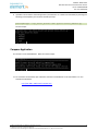
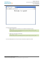
RIoTboard Web Server Master Class
Hardware Kit User Manual
This document contains:
- RIoTboard User Manual v1.0
- XTRINSIC-SENSE Board User Manual
USER MANUAL v1.0
Date: 01/20/2014
Table of Contents
1
2
BOARD OVERVIEW ........................................................................................................................... 7
1.1
PRODUCT INTRODUCTION ............................................................................................................... 7
1.2
FEATURES .................................................................................................................................... 8
HARDWARE DESCRIPTION ............................................................................................................. 11
2.1
PROCESSOR ............................................................................................................................... 11
2.1.1
Core Features ..................................................................................................................... 11
2.1.2
External memory interfaces: .............................................................................................. 12
2.1.3
Interface to external devices .............................................................................................. 13
2.1.4
Advanced Power Management unit................................................................................... 14
2.1.5
Hardware Accelerators ...................................................................................................... 14
2.2
EXPANDED CHIP INTRODUCTION .................................................................................................... 15
2.2.1
MT41K256M16HA-125:E ................................................................................................... 15
2.2.2
MMPF0100NPAEP .............................................................................................................. 15
2.2.3
AR8035............................................................................................................................... 15
2.2.4
FE1.1 .................................................................................................................................. 16
2.2.5
SGTL5000 ........................................................................................................................... 16
2.3
EXPANDED CHIP INTRODUCTION .................................................................................................... 17
2.3.1
Power Input Jack ................................................................................................................ 17
2.3.2
LVDS Interface .................................................................................................................... 18
2.3.3
HDMI Interface................................................................................................................... 19
2.3.4
Microphone Input Jack....................................................................................................... 21
2.3.5
Audio Output Jack .............................................................................................................. 22
2.3.6
SD Card Interface ............................................................................................................... 23
2.3.7
uSD/MMC Card Interface ................................................................................................... 24
2.3.8
CSI Interface ....................................................................................................................... 25
2.3.9
Camera Interface ............................................................................................................... 26
Page | 2
USER MANUAL v1.0
Date: 01/20/2014
3
4
5
2.3.10
JTAG Interface ................................................................................................................ 28
2.3.11
Mini USB Interface ......................................................................................................... 29
2.3.12
Serial Port ...................................................................................................................... 30
2.3.13
Expansion Port Interface ................................................................................................ 31
2.3.14
Mini USB Interface (OpenSDA) ....................................................................................... 33
2.3.15
RGMII LAN Interface ...................................................................................................... 34
2.3.16
USB HUB Interface ......................................................................................................... 35
2.3.17
Boot Configuration Select .............................................................................................. 36
2.3.18
Reset Switch ................................................................................................................... 38
2.3.19
LEDs ............................................................................................................................... 39
GETTING STARTED ......................................................................................................................... 40
3.1
SOFTWARE FEATURES................................................................................................................... 40
3.2
LINUX SYSTEM ............................................................................................................................ 40
3.3
ANDROID SYSTEM ....................................................................................................................... 41
3.4
SETTING UP TERMINAL EMULATION ................................................................................................ 42
DOWNLOADING AND RUNNING THE SYSTEM .............................................................................. 43
4.1
DOWNLOAD AND RUN LINUX OR ANDROID SYSTEM ........................................................................... 43
4.2
DISPLAY MODE CONFIGURATIONS FOR LINUX & ANDROID SYSTEMS ..................................................... 46
MAKING IMAGES ........................................................................................................................... 48
5.1
5.1.1
Getting Tools and Source Code .......................................................................................... 48
5.1.2
Compiling System Images .................................................................................................. 48
5.2
6
MAKING IMAGES FOR LINUX ......................................................................................................... 48
MAKING IMAGES FOR AN ANDROID SYSTEM ..................................................................................... 49
5.2.1
Getting Repo Source Code ................................................................................................. 49
5.2.2
Compiling System Images .................................................................................................. 50
ESD PRECAUTIONS AND PROPER HANDLING PROCEDURES......................................................... 52
Page | 3
USER MANUAL v1.0
Date: 01/20/2014
LIST OF FIGURES
Figure 1-1 Functional Block Diagram ............................................................................................... 7
Figure 1-2 RIoTboard top view ......................................................................................................... 8
Figure 1-3 RIoTboard bottom view .................................................................................................. 9
Figure 2-1 Block Diagram of i.MX 6Solo......................................................................................... 12
Figure 2-2 Power Interface............................................................................................................. 17
Figure 2-3 LVDS Interface............................................................................................................... 18
Figure 2-4 HDMI Interface ............................................................................................................. 19
Figure 2-5 MIC Input ...................................................................................................................... 21
Figure 2-6 Audio Output Jack ......................................................................................................... 22
Figure 2-7 SD Card Interface .......................................................................................................... 23
Figure 2-8 uSD/MMC Card Interface .............................................................................................. 24
Figure 2-9 CSI Interface .................................................................................................................. 25
Figure 2-10 Camera Interface ........................................................................................................ 26
Figure 2-11 JTAG Interface ............................................................................................................. 28
Figure 2-12 Mini USB Interface ...................................................................................................... 29
Figure 2-13 Serial Port ................................................................................................................... 30
Figure 2-14 Expansion Port ............................................................................................................ 31
Figure 2-15 Mini USB (OpenSDA)Interface..................................................................................... 33
Figure 2-16 RGMII LAN Interface ................................................................................................... 34
Figure 2-17 USB Host Interface ...................................................................................................... 35
Figure 2-18 Boot Configuration Select ........................................................................................... 36
Figure 2-19 Reset Switch ................................................................................................................ 38
Figure 2-20 LEDs ............................................................................................................................ 39
Page | 4
USER MANUAL v1.0
Date: 01/20/2014
Figure 3-1 COM Properties ............................................................................................................. 42
Figure 4-1 Boot Configuration Switch ............................................................................................ 43
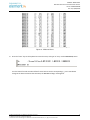
LIST OF TABLES
Table 2-1 Power Interface .............................................................................................................. 17
Table 2-2 LVDS Interface ................................................................................................................ 18
Table 2-3 HDMI Interface ............................................................................................................... 19
Table 2-4 MIC Input Jack ................................................................................................................ 21
Table 2-5 Audio Output Jack .......................................................................................................... 22
Table 2-6 SD Card Interface ........................................................................................................... 23
Table 2-7 uSD/MMC Card Interface ............................................................................................... 24
Table 2-8 CSI Interface ................................................................................................................... 25
Table 2-9 Camera Interface ........................................................................................................... 27
Table 2-10 JTAG Interface .............................................................................................................. 28
Table 2-11 Mini USB Interface ....................................................................................................... 29
Table 2-12 Serial Port ..................................................................................................................... 30
Table 2-13 Expansion Port Interface .............................................................................................. 31
Table 2-14 Mini USB (OpenSDA) Interface ..................................................................................... 33
Table 2-15 RGMII LAN interface..................................................................................................... 34
Table 2-16 USB Host Interface ....................................................................................................... 35
Table 2-17 Boot Configuration Select ............................................................................................ 37
Table 2-18 Reset Switch ................................................................................................................. 38
Table 2-19 LEDs .............................................................................................................................. 39
Table 3-1 OS and Drivers ................................................................................................................ 40
Table 3-2 Images Required by Linux............................................................................................... 40
Page | 5
USER MANUAL v1.0
Date: 01/20/2014
Table 3-3 Storage Partitions for Linux ............................................................................................ 41
Table 3-4 Images Required by Android .......................................................................................... 41
Table 3-5 Storage Partitions for Android........................................................................................ 41
Table 4-1 Boot Switch Configuration – Serial Download................................................................ 43
Table 4-2 Boot Switch Configuration - eMMC ................................................................................ 46
Table 4-3 Boot Switch Configuration – SD ..................................................................................... 46
Table 5-1 Images and Directories .................................................................................................. 51
Page | 6
USER MANUAL v1.0
Date: 01/20/2014
1
1.1
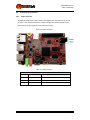
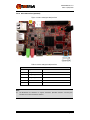
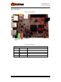
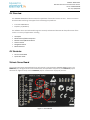
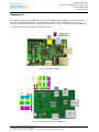
Board Overview
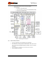
Product Introduction
The RIoTboard is an evaluation platform featuring the powerful i.MX 6Solo, a
multimedia application processor with ARM Cortex-A9 core at 1 GHz from Freescale
Semiconductor. The platform helps evaluate the rich set of peripherals and includes
a 10/100/Gb Ethernet port, HDMI v1.4, LVDS, analog headphone/microphone, uSD
and SD card interface, USB, serial port, JTAG, 2 camera interfaces, GPIO boot
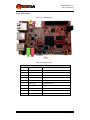
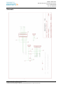
configuration interface, and expansion port, as shown in Figure 1-1.
The RIoTboard can be used in the following applications:
•
•
•
•
•
•
•
•
Netbooks (web tablets)
Nettops (Internet desktop devices)
High-end mobile Internet devices (MID)
High-end PDAs
High-end portable media players (PMP) with HD video capability
Portable navigation devices (PNDs)
Industrial control and Test and measurement (T&M)
Single board computers (SBCs)
Figure 1-1 Functional Block Diagram
Page | 7
USER MANUAL v1.0
Date: 01/20/2014
1.2
Features
The RIoTboard is based on the i.MX 6Solo processor from Freescale Semiconductor
integrating all the functionalities of this multimedia application processor with the
following features:
•
•
•
Mechanical Parameters
o Working Temperature: 0°C - 50°C
o Humidity Range: 20% - 90%
o Dimensions: 120mm x 75mm
o Input Voltage: +5V
Processor
o ARM Cortex A9 MPCore™ Processor at 1 GHz
o High-performing video processing unit which covers SD-level and HDlevel video decoders and SD-level encoders as a multi-standard video
codec engine
o An OpenGL® ES 2.0 3D graphics accelerator with a shader and a 2D
graphics accelerator for superior 3D, 2D, and user interface
acceleration
Memories
o 1GByte of 16-bit wide DDR3 @ 800MHz
o 4GB eMMC
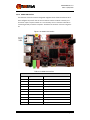
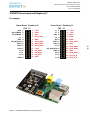
Figure 1-2 RIoTboard top view
Page | 8
USER MANUAL v1.0
Date: 01/20/2014
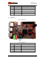
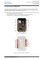
•
Media Interfaces
o Analog headphone/microphone, 3.5mm audio jack
o LVDS interface
o HDMI interface
o Parallel RGB interface(Expansion port)
o Camera interface (Support CCD or CMOS camera)
o MIPI lanes at 1 Gbps
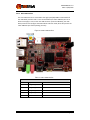
Figure 1-3 RIoTboard bottom view
•
Data Transfer Interfaces
o Debug Ports:
3 pin TTL level
o Serial Ports:
UART3,4,5, 3 line serial port, TTL Logic (Expansion port)
o USB Ports:
1 x USB2.0 OTG, mini USB, high-speed, 480Mbps
4 x USB2.0 HOST, Type A, high-speed, 480Mbps
o uSD card interface
o SD card interface
o 10M/100M/Gb Ethernet Interface (RJ45 jack)
Page | 9
USER MANUAL v1.0
Date: 01/20/2014
o
o
o
o
o
o
•
Others
o
o
o
o
o
o
2 channel I2C interface (Expansion port)
2 channel SPI interface (Expansion port)
3 channel PWM interface (Expansion port)
GPIO (Expansion port)
10-pin JTAG interface
Open SDA
1 Power LED
1 Open SDA LED
2 User-defined LEDs
1 DC Jack
1 Reset button
Boot configuration interface
Page | 10
USER MANUAL v1.0
Date: 01/20/2014
2
Hardware Description
2.1
Processor
The i.MX 6Solo processor represents Freescale Semiconductor’s latest achievement in
integrated multimedia applications processors, which are part of a growing family of
multimedia-focused products that offer high performance processing and are
optimized for lowest power consumption.
The processor features Freescale’s advanced implementation of the single ARM™
Cortex-A9 core, which operates at speeds up to 1 GHz. It includes 2D and 3D graphics
processors, 3D 1080p video processing, and integrated power management. The
processor provides a 16/32-bit DDR3/LVDDR3-800 memory interface and a number of
other interfaces for connecting peripherals, such as WLAN, Bluetooth™, GPS, hard drive,
displays, and camera sensors.
2.1.1
Core Features
The i.MX 6Solo processor is based on the ARM Cortex A9 MPCore™ platform with the
following features:
•
•
•
•
ARM Cortex A9 MPCore™ CPU Processor (with TrustZone)
The core configuration is symmetric, where the core includes:
o 32 KByte L1 Instruction Cache
o 32 KByte L1 Data Cache
o Private Timer and Watchdog
o Cortex-A9 NEON MPE (Media Processing Engine) Co-processor
The ARM Cortex A9 MPCore™ complex includes:
o General Interrupt Controller (GIC) with 128 interrupt support
o Global Timer
o Snoop Control Unit (SCU)
o 512 KB unified I/D L2 cache
o Two Master AXI (64-bit) bus interfaces output of L2 cache
o NEON MPE coprocessor
SIMD Media Processing Architecture
NEON register file with 32x64-bit general-purpose registers
NEON Integer execute pipeline (ALU, Shift, MAC)
NEON dual, single-precision floating point execute pipeline
(FADD, FMUL)
NEON load/store and permute pipeline
The memory system consists of the following components:
o Level 1 Cache--32 KB Instruction, 32 KB Data cache per core
Page | 11
USER MANUAL v1.0
Date: 01/20/2014
o
o
Level 2 Cache--Unified instruction and data (512 KByte)
On-Chip Memory:
Boot ROM, including HAB (96 KB)
Internal multimedia / shared, fast access RAM (OCRAM, 128 KB)
Secure/non-secure RAM (16 KB)
Figure 2-1 Block Diagram of i.MX 6Solo
2.1.2
External memory interfaces:
•
•
•
•
16/32-bit LP-DDR2-800, 16/32-bit DDR3-800 and LV-DDR3-800.
8-bit NAND-Flash, including support for Raw MLC/SLC, 2 KB, 4 KB, and 8 KB
page size, BA-NAND, PBA-NAND, LBA-NAND, OneNAND™ and others. BCH ECC
up to 40 bit.
16/32-bit NOR Flash. All WEIMv2 pin are muxed on other interfaces.
16/32-bit PSRAM, Cellular RAM
Page | 12
USER MANUAL v1.0
Date: 01/20/2014
2.1.3
Interface to external devices
Each i.MX 6Solo processor enables the following interfaces to external devices
(some of them are muxed and not available simultaneously):
•
Displays--Total five interfaces available. Total raw pixel rate of all interfaces is
up to 450 Mpixels/sec, 24 bpp. Up to two interfaces may be active in parallel.
o One Parallel 24-bit display port, up to 225 Mpixes/sec (for example,
WUXGA at 60 Hz or dual HD1080 and WXGA at 60 Hz)
o LVDS serial ports One port up to 165 Mpixels/sec or two ports up to
85 MP/sec (for example, WUXGA at 60 Hz) each
o HDMI 1.4 port
o MIPI/DSI, two lanes at 1 Gbps
o EPDC, Color, and monochrome E-INK, up to 1650x2332 resolution and
5-bit grayscale
Camera sensors:
o Two parallel Camera ports (up to 20 bit and up to 240 MHz peak)
o MIPI CSI-2 serial camera port, supporting from 80 Mbps to 1 Gbps
speed per data lane. The CSI-2 Receiver core can manage one clock
lane and up to two data lanes. Each i.MX 6Solo processor has two
lanes.
Expansion cards:
o Four MMC/SD/SDIO card ports all supporting:
1-bit or 4-bit transfer mode specifications for SD and SDIO
cards up to UHS-I SDR-104 mode (104 MB/s max)
1-bit, 4-bit, or 8-bit transfer mode specifications for MMC cards
up to 52 MHz in both SDR and DDR modes (104 MB/s max)
USB
o One high speed (HS) USB 2.0 OTG (Up to 480 Mbps), with integrated HS
USB PHY
o Three USB 2.0 (480 Mbps) hosts
One HS host with integrated High Speed PHY
Two HS hosts with integrated HS-IC USB (High Speed Inter-Chip
USB) PHY
Expansion PCI Express port (PCIe) v2.0 one lane
o PCI Express (Gen 2.0) dual mode complex, supporting Root complex
operations and Endpoint operations. Uses x1 PHY configuration.
Miscellaneous IPs and interfaces:
o Three I2S/SSI/AC97,up to 1.4 Mbps each
o Enhanced Serial Audio Interface ESAI), up to 1.4 Mbps per channel
o Five UARTs, up to 4.0 Mbps each
Providing RS232 interface
Supporting 9-bit RS485 multidrop mode
:
•
•
•
•
•
Page | 13
USER MANUAL v1.0
Date: 01/20/2014
o
o
o
o
o
o
o
o
o
o
o
o
2.1.4
One of the five UARTs (UART1) supports 8-wire while the other
four support 4-wire. This is due to the SoC IOMUX limitation,
since all UART IPs are identical
Four eCSPI (Enhanced CSI)
Four I2C, supporting 400 kbps
Gigabit Ethernet Controller(IEEE1588 compliant), 10/100/1000 Mbps
Four Pulse Width Modulators (PWM)
System JTAG Controller (SJC)
GPIO with interrupt capabilities
8x8 Key Pad Port (KPP)
Sony Philips Digital Interface (SPDIF), Rx and Tx
Two Controller Area Network (FlexCAN), 1 Mbps each
Two Watchdog timers (WDOG)
Audio MUX (AUDMUX)
MLB (MediaLB) provides interface to MOST Networks (MOST25, MOST50,
MOST150) with the option of DTCP cipher accelerator
Advanced Power Management unit
The i.MX 6Solo processors integrate advanced power management unit and
controllers:
•
•
•
•
•
•
2.1.5
Provide PMU, including LDO supplies, for on-chip resources
Use Temperature Sensor for monitoring the die temperature
Support DVFS techniques for low power modes
Use SW State Retention and Power Gating for ARM and MPE
Support various levels of system power modes
Use flexible clock gating control scheme
Hardware Accelerators
The i.MX 6Solo processor uses dedicated hardware accelerators to meet the targeted
multimedia performance. The use of hardware accelerators is a key factor in obtaining
high performance at low power consumption numbers, while having the CPU core
relatively free for performing other tasks.
The i.MX 6Solo processor incorporates the following hardware accelerators:
•
•
•
•
•
VPU--Video Processing Unit
IPUv3H--Image Processing Unit version 3H
GPU3Dv5--3D Graphics Processing Unit (OpenGL ES 2.0) version 5
GPU2Dv2--2D Graphics Processing Unit (BitBlt)
ASRC--Asynchronous Sample Rate Converter
Page | 14
USER MANUAL v1.0
Date: 01/20/2014
Security functions are enabled and accelerated by the following hardware:
• ARM TrustZone including the TZ architecture (separation of interrupts, memory
mapping, etc.)
• SJC--System JTAG Controller. Protecting JTAG from debug port attacks by
regulating or blocking the access to the system debug features.
• CAAM--Cryptographic Acceleration and Assurance Module, containing
cryptographic and hash engines, 16 KB secure RAM and True and Pseudo
Random Number Generator (NIST certified)
• SNVS--Secure Non-Volatile Storage, including Secure Real Time Clock
• CSU--Central Security Unit. Enhancement for the IC Identification Module (IIM).
Will be configured during boot and by eFUSEs and will determine the security
level operation mode as well as the TZ policy.
• A-HAB Advanced High Assurance Boot--Hv4 with the new embedded
enhancements:SHA-256, 2048-bit RSA key, version control mechanism, warm
boot, CSU, and TZ initialization.
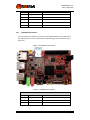
2.2
Expanded Chip Introduction
2.2.1
MT41K256M16HA-125:E
The board has 1GB of SDRAM (2x512MB). Micron’s MT41K256M16 is a 512MB DDR3
Synchronous DRAM, ideally suited for the main memory applications which require
large memory density and high bandwidth.
2.2.2
MMPF0100NPAEP
The PF0100 Power Management Integrated Circuit (PMIC) provides a highly
programmable/ configurable architecture, with fully integrated power devices and
minimal external components. With up to six buck converters, six linear regulators, RTC
supply, and coin-cell charger, the PF0100 can provide power for a complete system,
including applications processors, memory, and system peripherals, in a wide range of
applications. With on-chip One Time Programmable (OTP) memory, the PF0100 is
available in pre-programmed standard versions, or non-programmed to support
custom programming. The PF0100 is defined to power the entire embedded MCU
platform solution similar to i.MX6 based eReader, IPTV, medical monitoring and
home/factory automation.
2.2.3
AR8035
AR8035 is a single port 10/100/1000 Mbps tri-speed Ethernet PHY feaured with low
power and low cost. AR8035 supports MAC.TM RGMII interface and IEEE 802.3az-2010,
Energy Efficient Ethernet (EEE) standard through proprietary SmartEEE technology,
improving energy efficiency in systems using legacy MAC devices without 802.3az
Page | 15
USER MANUAL v1.0
Date: 01/20/2014
support. The RIOT Board can be connected to a network hub directly through a cable. It
also can be directly connected with a computer through a crossover cable which is
provided with the kit.
2.2.4
FE1.1
FE1.1 is a USB 2.0 high-speed 4-port hub solution. It uses USB3320 to provide 4
extended USB interface with support for high-speed (480MHz), full-speed (2MHz) and
low-speed (1.5MHz) mode.
2.2.5
SGTL5000
The SGTL5000 is a low power stereo Codec with Headphone Amp from Freescale, and is
designed to provide a complete audio solution for portable products needing line-in,
mic-in, line-out, headphone-out, and digital I/O. Deriving its architecture from best-inclass Freescale-integrated products currently on the market, the SGTL5000 is able to
achieve ultra low-power with very high performance and functionality, all in one of the
smallest footprints available.
Designed with features such as capless headphone and an integrated PLL to allow clock
reuse within the system, it helps customers achieve a lower overall system cost.
Page | 16
USER MANUAL v1.0
Date: 01/20/2014
2.3
Expanded Chip Introduction
2.3.1
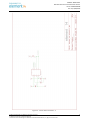
Power Input Jack
A 5V/1A AC-to-DC power supply needs to be plugged into the Power Jack (J1) on the
board. It is not recommended to use a higher voltage since possible damage to the
board may result due to failure of the protection circuitry.
Figure 2-2 Power Interface
Table 2-1 Power Interface
J1
Pin
Signal
Function
1
GND
GND
2
NC
NC
3
+5V
Power supply (+5V) 1A (Type)
Page | 17
USER MANUAL v1.0
Date: 01/20/2014
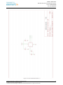
2.3.2
LVDS Interface
Figure 2-3 LVDS Interface
The LVDS Interface supports LVDS8000-97C designed by Embest.
Table 2-2 LVDS Interface
J2
Pin
Signal
Function
1
3V3
+3.3V
2
LVDS_TX2_P
LVDS data2+
3
LVDS_TX2_N
LVDS data2-
4
GND
GND
5
LVDS_TX1_P
LVDS data1+
6
LVDS_TX1_N
LVDS data1-
7
GND
GND
8
LVDS_TX0_P
LVDS data0+
9
LVDS_TX0_N
LVDS data-
10
GND
GND
11
LVDS_CLK_P
LVDS CLK+
12
LVDS_CLK_N
LVDS CLK-
Page | 18
USER MANUAL v1.0
Date: 01/20/2014
2.3.3
13
LCD_PWR_EN
Touch reset signal
14
Touch_Int
Touch interrupt signal
15
I2C_SCL
IIC master serial clock
16
I2C_SDA
IIC master serial data
17
LED_PWR_EN
Backlight enable
18
5V
+5V
19
PWM
Pulse Width Modulation
HDMI Interface
Figure 2-4 HDMI Interface
Table 2-3 HDMI Interface
J3
Pin
Signal
Function
1
HDMI_D2P
HDMI differential pairs data2+
2
GND
GND
3
HDMI_D2M
HDMI differential pairs data2-
4
HDMI_D1P
HDMI differential pairs data1+
5
GND
GND
Page | 19
USER MANUAL v1.0
Date: 01/20/2014
6
HDMI_D1M
HDMI differential pairs data1-
7
HDMI_D0P
HDMI differential pairs data0+
8
GND
GND
9
HDMI_D0M
HDMI differential pairs data0-
10
HDMI_CLKP
HDMI differential pairs clock+
11
GND
GND
12
HDMI_CLKM
HDMI differential pairs clock-
13
NC
NC
14
NC
NC
15
BI2C2_SCL
IIC2 serial clock
16
BI2C2_SDA
IIC2 serial data
17
GND
GND
18
5Vin
5V
19
HDMI_HPD
HDMI detect
20
GNF_DVI
GND
Page | 20
USER MANUAL v1.0
Date: 01/20/2014
2.3.4
Microphone Input Jack
The RIoTboard provides a 3.5mm stereo connector for a microphone input, as shown in
Figure 2-5. A mono microphone will input its signal though the tip of the 3.5mm plug.
Figure 2-5 MIC Input
Table 2-4 MIC Input Jack
J4
Pin
Signal
Function
1
GND_ANALOG
Analog GND
2
MIC_IN_P
MIC input analog GND
3
GND_ANALOG
Analog GND
4
GND_ANALOG
Analog GND
5
MIC_IN_P
MIC input analog GND
Page | 21
USER MANUAL v1.0
Date: 01/20/2014
2.3.5
Audio Output Jack
A headphone with a standard 3.5mm stereo jack can be connected to the Audio Output
jack at the point shown in Figure 2-6.
Figure 2-6 Audio Output Jack
Table 2-5 Audio Output Jack
J5
Pin
Signal
Function
1
GND_ANALOG
Analog GND
2
LINEOUT_L
Left output
3
LINEOUT_R
Right output
4
LINEOUT_R
Right output
5
LINEOUT_L
Left output
Page | 22
USER MANUAL v1.0
Date: 01/20/2014
2.3.6
SD Card Interface
Figure 2-7 SD Card Interface
Table 2-6 SD Card Interface
J6
Pin
Signal
Function
1
SD2_DAT3
Card data 3
2
SD2_CMD
Command signal
3
GND
GND
4
3P3V
3.3V
5
SD2_CLK
Clock
6
VSS
GND
7
SD2_DAT0
Card data 0
8
SD2_DAT1
Card data 1
9
SD2_DAT2
Card data 2
Page | 23
USER MANUAL v1.0
Date: 01/20/2014
2.3.7
10
SD2_CD
Card detect
11
SD2_WP
Card write protected
12
GND
GND
13
GND
GND
14
GND
GND
15
GND
GND
uSD/MMC Card Interface
The micro SD Card Connector (J7) connects a 4-bit parallel data bus to the SD3 port of
the i.MX 6 processor. The micro SD Card is inserted facing up at the location shown in
Figure 2-8.
Figure 2-8 uSD/MMC Card Interface
Table 2-7 uSD/MMC Card Interface
J7
Pin
Signal
Function
1
SD3_DAT2
Card data 2
2
SD3_DAT3
Card data 3
3
CMD
Card command signal
Page | 24
USER MANUAL v1.0
Date: 01/20/2014
2.3.8
4
3P3V
3P3V
5
SD3_CLK
Card clock
6
VSS
GND
7
SD3_DAT0
Card data 0
8
SD3_DAT1
Card data 1
9
SD3_CD
Card detect
10
PGND
GND
CSI Interface
Figure 2-9 CSI Interface
Table 2-8 CSI Interface
J8
Pin
Signal
Function
1
5VIN
5V
2
5VIN
5V
3
GND
GND
4
GND
GND
Page | 25
USER MANUAL v1.0
Date: 01/20/2014
2.3.9
5
P2V8_VGEN6
2.8V
6
CSI_MCLK
CSI clock
7
GND
GND
8
CSI_RST
CSI reset
9
CSI_EN
CSI data enable
10
I2C4_SCL
IIC2 serial clock
11
I2C4_SDA
IIC2 serial data
12
GND
GND
13
CSI_CLK0M
CSI differential pairs clock0-
14
CSI_CLK0P
CSI differential pairs clock0+
15
GND
GND
16
CSI_D0M
CSI differential pairs data0-
17
CSI_D0P
CSI differential pairs data0+
18
GND
GND
19
CSI_D1M
CSI differential pairs data1-
20
CSI_D1P
CSI differential pairs data1+
Camera Interface
Figure 2-10 Camera Interface
Page | 26
USER MANUAL v1.0
Date: 01/20/2014
Table 2-9 Camera Interface
J9
Pin
Signal
Function
1
GND
GND
2
NC
NC
3
NC
NC
4
CSI0_DAT12
CSI0 capture data bit 12
5
CSI0_DAT13
CSI0 capture data bit 13
6
CSI0_DAT14
CSI0 capture data bit 14
7
CSI0_DAT15
CSI0 capture data bit 15
8
CSI0_DAT16
CSI0 capture data bit 16
9
CSI0_DAT17
CSI0 capture data bit 17
10
CSI0_DAT18
CSI0 capture data bit 18
11
CSI0_DAT19
CSI0 capture data bit 19
12
NC
NC
13
NC
NC
14
GND
GND
15
CSI0_PIXCLK
CSI0 pixel clock
16
GND
GND
17
CSI0_HSYNC
CSIO HSYNC
18
NC
NC
19
CSI0_VSYNC
CSIO VSYNC
20
VDD_NVCC
3.3V
21
CAM_MCLK
Camera clock
22
NC
NC
23
GND
GND
24
NC
NC
25
CAM_RST
CSI0 reset
26
CAM_EN
CSI0 data enable
27
I2C4_SDA
I2C2 serial data
28
I2C4_SCL
I2C2 serial clock
29
GND
GND
30
P1V8_SW4
1.8V
Page | 27
USER MANUAL v1.0
Date: 01/20/2014
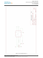
2.3.10 JTAG Interface
Figure 2-11 JTAG Interface
Table 2-10 JTAG Interface
J10
Pin
Signal
Function
1
VDD_NVCC
3.3V
2
JTAG_TMS
Test mode select
3
GND
GND
4
JTAG_TCK
Test clock
5
GND
GND
6
JTAG_TDO
Test data output
7
JTAG_MOD
Test mode
8
JTAG_TDI
Test data input
9
JTAG_nTRST
Test system reset
10
RESET_N
Reset
Page | 28
USER MANUAL v1.0
Date: 01/20/2014
2.3.11 Mini USB Interface
The mini USB connector is connected to the high-speed (HS) USB 2.0 OTG module of
the i.MX 6Solo processor and is cross connected with the lower USB Host port on J3.
When a 5V supply is seen on the mini USB connector (from the USB Host), the i.MX
6Solo processor will configure the OTG module to device mode, which will prevent the
lower USB Host port from operating correctly.
Figure 2-12 Mini USB Interface
Table 2-11 Mini USB Interface
J11
Pin
Signal
Function
1
USB_OTG_VBUS
+5V
2
USB_OTG_DN
USB data-
3
USB_OTG_DP
USB data+
4
USB_OTG_ID
USB ID
5
GND
GND
Page | 29
USER MANUAL v1.0
Date: 01/20/2014
2.3.12 Serial Port
Figure 2-13 Serial Port
Table 2-12 Serial Port
J18
Pin
Signal
Function
1
UART2_TXD
UART2 transmit data
2
UART2_RXD
UART2 receive data
3
GND
GND
Page | 30
USER MANUAL v1.0
Date: 01/20/2014
2.3.13 Expansion Port Interface
Figure 2-14 Expansion Port
Table 2-13 Expansion Port Interface
J13
Pin
Signal
Function
1
VDD_NVCC
3.3V
2
5VIN
5V
3
GND
GND
4
GND
GND
5
GPIO4_16
GPIO
6
CSPI3_CLK
SPI3 clock
7
GPIO4_17
GPIO
8
CSPI3_MOSI
SPI3 master output salve input
9
GPIO4_18
GPIO
10
CSPI3_MISO
SPI3 master input salve output
11
GPIO4_19
GPIO
12
CSPI3_CS0
SPI3 chip select 0
13
CSPI3_CS1
SPI3 chip select 1
Page | 31
USER MANUAL v1.0
Date: 01/20/2014
14
CSPI2_CS1
SPI2 chip select 1
15
GPIO4_31
GPIO
16
CSPI2_MOSI
SPI2 master output salve input
17
GPIO5_05
GPIO
18
CSPI2_MISO
SPI2 master input salve output
19
GPIO5_06
GPIO
20
CSPI2_CS0
SPI2 chip select 0
21
GPIO5_07
GPIO
22
CSPI2_CLK
SPI2 clock
23
GPIO5_08
GPIO
24
UART3_RXD
UART3 receive data
25
GPIO4_26
GPIO
26
UART3_TXD
UART3 transmit data
27
GPIO4_27
GPIO
28
UART4_RXD
UART4 receive data
29
CSPI3_RDY
SPI3 data validation
30
UART4_TXD
UART4 transmit data
31
I2C3_SCL
I2C3 master serial clock
32
UART5_RXD
UART5 receive data
33
I2C3_SDA
I2C3 master serial data
34
UART5_TXD
UART5 transmit data
35
I2C4_SCL
I2C4 master serial clock
36
PWM1
Pulse Width Modulation
37
I2C4_SDA
I2C4 master serial data
38
PWM2
Pulse Width Modulation
39
GND
GND
40
PWM3
Pulse Width Modulation
Page | 32
USER MANUAL v1.0
Date: 01/20/2014
2.3.14 Mini USB Interface (OpenSDA)
Figure 2-15 Mini USB (OpenSDA)Interface
Table 2-14 Mini USB (OpenSDA) Interface
J14
Pin
Signal
Function
1
V5V_SDA
+5V
2
SDA_USB_DN
SDA USB data-
3
SDA_USB_DP
SDA USB data+
4
NC
NC
5
GND
GND
Note:
The RIoTboard has hardware to support Freescale’s OpenSDA interface. Currently this
interface has not been enabled in software
Page | 33
USER MANUAL v1.0
Date: 01/20/2014
2.3.15 RGMII LAN Interface
The Ethernet connector contains integrated magnetic which allows the Ethernet IC to
auto configure the port for the correct connection to either a switch or directly to a
host PC on a peer-to-peer network. It is not necessary to use a crossover cable when
connecting directly to another computer. The Ethernet connector is shown in Figure 216.
Figure 2-16 RGMII LAN Interface
Table 2-15 RGMII LAN interface
J15
Pin
Signal
Function
1
TD1+
TD1+ output
2
TD1-
TD1- output
3
TD2+
TD2+ output
4
TD2-
TD2- output
5
TCT
2.5V power for TD
6
RCT
2.5V power for RD
7
RD1+
RD1+ input
8
RD1-
RD1- input
9
RD2+
RD2+ input
10
RD2-
RD2- input
Page | 34
USER MANUAL v1.0
Date: 01/20/2014
11
GRLA
Green LED link signal
12
GRLC
Power supply for green LED
13
YELC
Yellow LED action signal
14
YELA
Power supply for yellow LED
2.3.16 USB HUB Interface
Figure 2-17 USB Host Interface
Table 2-16 USB Host Interface
HUB1
Pin
Signal
Function
1
USB_PWR3
+5V
2
USB_DM3
USB data-
3
USB_DP3
USB data+
4
GND
GND
5
USB_PWR4
+5V
6
USB_DM4
USB data-
7
USB_DP4
USB data+
8
GND
GND
Page | 35
USER MANUAL v1.0
Date: 01/20/2014
HUB2
Pin
Signal
Function
1
USB_PWR1
+5V
2
USB_DM1
USB data-
3
USB_DP1
USB data+
4
GND
GND
5
USB_PWR2
+5V
6
USB_DM2
USB data-
7
USB_DP2
USB data+
8
GND
GND
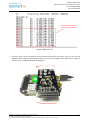
2.3.17 Boot Configuration Select
Figure 2-18 Boot Configuration Select
Page | 36
USER MANUAL v1.0
Date: 01/20/2014
Table 2-17 Boot Configuration Select
SW1
Pin
Signal
Function
1
P3V0_STBY
P3V0_STBY
2
P3V0_STBY
P3V0_STBY
3
VDD_NVCC
VDD_NVCC
4
VDD_NVCC
VDD_NVCC
5
VDD_NVCC
VDD_NVCC
6
VDD_NVCC
VDD_NVCC
7
VDD_NVCC
VDD_NVCC
8
VDD_NVCC
VDD_NVCC
9
EIM_DA11
BT_CFG2_3
10
EIM_DA12
BT_CFG2_4
11
EIM_DA13
BT_CFG2_5
12
EIM_DA14
BT_CFG2_6
13
EIM_DA5
BT_CFG1_5
14
EIM_DA6
BT_CFG1_6
15
BOOT_MODE0
BOOT_MODE0
16
BOOT_MODE1
BOOT_MODE1
Page | 37
USER MANUAL v1.0
Date: 01/20/2014
2.3.18 Reset Switch
Figure 2-19 Reset Switch
Table 2-18 Reset Switch
S1
Pin
Signal
Function
1
GND
GND
2
POR_B
System reset
3
NC
NC
4
NC
NC
Page | 38
USER MANUAL v1.0
Date: 01/20/2014
2.3.19 LEDs
Figure 2-20 LEDs
Table 2-19 LEDs
LED
Reference
Function
D45
User-defined LED
D46
User-defined LED
D47
Power LED
D49
OpenSDA LED
Page | 39
USER MANUAL v1.0
Date: 01/20/2014
3
Getting Started
Before you start to use RIoTboard, please read the following sections to get yourself
familiar with the system images, driver code and tools which might be involved during
development process.
NOTE:
3.1
All images and tools for Android and Linux can be downloaded
from www.element14.com/riotboard
Software Features
The table shown below lists the versions of Linux and Android systems, as well as
the device drivers.
Table 3-1 OS and Drivers
Types
Linux
OS
Ubuntu
Android
Serial
RTC
Net
Display
Device
MMC/SD
Drivers
USB
Audio
Camera
LED
3.2
Notes
Version 3.0.35
Version 11.10
Version 4.3
Series driver
Hardware clock driver
10/100/Gb IEEE1588 Ethernet
Two display ports (LVDS, and HDMI 1.4a)
Two SD 3.0/SDXC card slot & eMMC
5 High speed USB ports (4xHost, 1xOTG)
Analog (headphone & mic) and Digital (HDMI)
Two camera ports (1xParallel, 1x MIPI CSI-2)
User leds driver
Linux System
The following tables list the specific images and eMMC storage patitions required to
build a Linux system.
Table 3-2 Images Required by Linux
Images
u-boot image
kernel image
rootfs image
Paths
u-boot-mx6solo-riot.bin
uImage
oneiric.tgz
Page | 40
USER MANUAL v1.0
Date: 01/20/2014
Table 3-3 Storage Partitions for Linux
Partition
type/index
Name
Start Offset
Size
File
System
N/A
BOOT
Loader
0
1MB
N/A
N/A
Kernel
1M
N/A
Primary 1
Rootfs
10M
9MB
Total Other
u-bootmx6soloriot.bin
uImage
EXT3
oneiric.tgz
Content
Partition type/index: defined in MBR.
Name: only meaningful in Android. You can ignore it when creating these partitions.
Start Offset: shows where partition starts with unit in MB.
3.3
Android System
The following tables list the specific images and eMMC storage patitions required to
build an Android system.
Table 3-4 Images Required by Android
Images
u-boot image
boot image
Android system root image
Recovery root image
Paths
u-boot-mx6solo-riot.bin
boot.img
system.img
recovery.img
Table 3-5 Storage Partitions for Android
Partition type/index
N/A
Name
BOOT
Loader
Start Offset
Size
0
1MB
File System
N/A
boot.img format,
a kernel +
ramdisk
boot.img format,
a kernel +
ramdisk
Primary 1
Boot
8M
8MB
Primary 2
Recovery
Follow Boot
8MB
Logic 4
(Extended 3)
DATA
follow
Recovery
> 1024MB
Logic 5
(Extended 3)
SYSTEM
Follow DATA
512MB
Logic 6 (Extended 3)
CACHE
follow
SYSTEM
512MB
Logic 7(Extended 3)
VENDOR
follow CACHE
8MB
Logic 9
(Extended 3)
Misc
Follow DATA
8M
N/A
Primary 4
MEDIA
Follow Misc
Total - Other
VFAT
EXT4 Mount at
/data
EXT4. Mount as
/system
EXT4. Mount as
/cache
Ext4 Mount at
/device
Content
bootloader
boot.img
recovery.img
Application data
storage for system
application.
Android system files
under /system/ dir
Android cache, for
image store for OTA
For Store MAC address
files.
For recovery store
bootloader message,
reserve.
For internal media
Page | 41
USER MANUAL v1.0
Date: 01/20/2014
Partition type/index
Name
Start Offset
Size
images
File System
Content
partition, in
/mnt/sdcard/ dir.
SYSTEM Partition: used to store Android system image.
DATA Partition: used to store applications’ unpacked data, system configuration
database, etc.
Under normal mode, the root file system is mounted from uramdisk. Under
recovery mode, the root file system is mounted from the RECOVERY partition.
3.4
Setting up Terminal Emulation
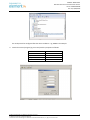
Connect the RIoTboard to a PC with the help of a serial cable. Launch a terminal
emulation program such as HyperTerminal or TeraTerm and configure the COM
parameters as show below.
Figure 3-1 COM Properties
Page | 42
USER MANUAL v1.0
Date: 01/20/2014
4
Downloading and Running the System
Now you can download the existing system to the RIoTboard and run it. The MFG tool
saved under linux\tools\ & android\tools\ will be used to download images.
NOTE:
4.1
All images and tools for Android and Linux can be downloaded
from www.element14.com/riotboard
Download and Run Linux or Android System
)
1
Copy all the system files to a root directory of your hard drive (assume C:\ is
the root directory).
)
2
Use a Mini USB cable to connect USB OTG interface on RIoTboard to the USB
Host on PC, and then open a Terminal window;
)
3
Set the boot switch SW1 on the RIoTboard to Serial Download Mode
according to the configurations as shown in the following table;
Table 4-1 Boot Switch Configuration – Serial Download
Switch
SW1
D1
OFF
D2
ON
D3
ON
D4
ON
D5
OFF
D6
ON
D7
ON
D8
ON
Figure 4-1 Boot Configuration Switch
Page | 43
USER MANUAL v1.0
Date: 01/20/2014
)
4
Modify the MFG tool configuration
Currently the Linux system on the RIoTboard supports only booting from
eMMC, but the Android system supports booting from both eMMC and SD
card. To select the device you want to program to, follow the instruction
below:
Modify the value of “name” in cfg.ini under Android flash image tool
Mfgtools-Rel-4.1.0_130816_MX6DL_UPDATER directory.
)
5
eMMC
--
name = Android-RIOT-eMMC
SD
--
name = Android-RIOT-SD
Prepare the image files
For Linux: Copy the Linux image files oneiric.tgz, u-boot-mx6solo-riot.bin and
uImage
to
the
Linux
flash
image
tool
Mfgtools-Rel4.1.0_130816_MX6DL_UPDATER\
Profiles\MX6DL
Linux
Update\OS
Firmware\files\ to overwrite the files with the same names
For Android: Copy the Android image files: u-boot-mx6solo-riot.bin and
according to the boot mode (SD/eMMC) to copy the boot.img, recovery.img
and system.img under SD/eMMC directory to Android flash image tool
Mfgtools-Rel-4.1.0_130816_MX6DL_UPDATER\
Profiles\MX6DL
Linux
Update\OS Firmware\files\android\, for overwriting the files with the same
names
)
6
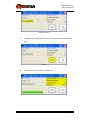
According to the system you want to boot, run the corresponding MFG tool
on your PC and power up the RIoTboard; the software window is shown below;
(the PC will install HID driver automatically if it is the first time connecting to
the RIoTboard)
For Linux system, the MFG tool is located at :
linux\tools\Mfgtools-Rel-4.1.0_130816_MX6DL_UPDATER;
For Android system, the MFG tool is located at :
android\tools\Mfgtools-Rel-4.1.0_130816_MX6DL_UPDATER;
Page | 44
USER MANUAL v1.0
Date: 01/20/2014
MFG tool window
)
7
Click Start in the following window; when download process is done, click Stop to
finish.
Click Start
)
8
When download process is done, click Exit to exit.
Page | 45
USER MANUAL v1.0
Date: 01/20/2014
)
9
Power off the RIoTboard and set the boot switches SW1 on it to eMMC boot
mode according to the configuration as shown In the following table;
Table 4-2 Boot Switch Configuration - eMMC
Switch
SW1
D1
ON
D2
OFF
D3
ON
D4
ON
D5
OFF
D6
ON
D7
ON
D8
ON
D7
OFF
D8
ON
Table 4-3 Boot Switch Configuration – SD
Switch
SW1
D1
ON
D2
OFF
D3
ON
D4
OFF
D5
OFF
D6
ON
After the switch is set, power up the RIoTboard to boot the system.
4.2
Display Mode Configurations for Linux & Android Systems
The system supports multiple display modes. Users can select an appropriate mode by
configuring u-boot parameters.
Please reboot the RIOT Board and press any key on your PC’s keyboard when the system
prompts you with a countdown in seconds as shown below:
U-Boot 2009.08-dirty (Oct 17 2013 - 17:08:06)
CPU: Freescale i.MX6 family TO1.1 at 792 MHz
Thermal sensor with ratio = 201
Temperature: 42 C, calibration data 0x5f55765f
mx6q pll1: 792MHz
mx6q pll2: 528MHz
mx6q pll3: 480MHz
mx6q pll8: 50MHz
ipg clock : 66000000Hz
ipg per clock : 66000000Hz
uart clock : 80000000Hz
cspi clock : 60000000Hz
ahb clock : 132000000Hz
axi clock : 198000000Hz
emi_slow clock: 99000000Hz
ddr clock : 396000000Hz
usdhc1 clock : 198000000Hz
usdhc2 clock : 198000000Hz
usdhc3 clock : 198000000Hz
usdhc4 clock : 198000000Hz
nfc clock : 24000000Hz
Board: i.MX6DL/Solo-SABRESD: unknown-board Board: 0x61011 [POR ]
Boot Device: MMC
I2C: ready
DRAM: 1 GB
MMC: FSL_USDHC: 0,FSL_USDHC: 1,FSL_USDHC: 2,FSL_USDHC: 3
In: serial
Out: serial
Err: serial
Page | 46
USER MANUAL v1.0
Date: 01/20/2014
Net: got MAC address from IIM: 00:00:00:00:00:00
----enet_board_init: phy reset
FEC0 [PRIME]
)
Hit any key to stop autoboot: 0 ( press any key to enter u-boot command mode
MX6Solo RIOT U-Boot >
)
1
Display with 9.7” LVDS Only
Execute the following instructions in u-boot mode to configure for 9.7-inch display
mode;
MX6Solo RIOT U-Boot > setenv bootargs console=ttymxc1,115200
init=/init nosmp video=mxcfb0:dev=ldb,bpp=32 video=mxcfb1:off
fbmem=10M vmalloc=400M androidboot.console=ttymxc1
androidboot.hardware=freescale
MX6Solo RIOT U-Boot > saveenv
)
2
Display with HDMI Only (Default mode)
Execute the following instructions in u-boot mode to configure for HDMI display
mode;
MX6Solo RIOT U-Boot > setenv bootargs console=ttymxc1,115200
init=/init nosmp video=mxcfb0:dev=hdmi,1280x720M@60,bpp=32
video=mxcfb1:off fbmem=10M vmalloc=400M
androidboot.console=ttymxc1 androidboot.hardware=freescale
MX6Solo RIOT U-Boot > saveenv
Page | 47
USER MANUAL v1.0
Date: 01/20/2014
5 Making Images
This Chapter will introduce how to make images by using BSP contained in the ISO. The
BSP is a collection of binary, source code, and support files that can be used to create a
u-boot bootloader, Linux kernel image, and Android file system for i.MX 6Solo RIOT
Board.
Note:
The following instructions are all executed under Ubuntu system.
Each instruction has been put a bullets “” before it to prevent confusion caused by the long
instructions that occupy more than one line in the context.
5.1
Making Images for Linux
Please strictly follow the steps listed below to make images for Linux system.
5.1.1
Getting Tools and Source Code
)
1
)
2
)
3
5.1.2
Execute the following instructions to get cross compiling toolchain;
$ cd ~
$ git clone git://github.com/embest-tech/fsl-linaro-toolchain.git
Execute the following instructions to get u-boot source code;
$ cd ~
$ git clone git://github.com/embest-tech/u-boot-imx.git –b embest_imx_3.0.35_4.0.0
Execute the following instructions to get kernel source code;
$ cd ~
$ git clone git://github.com/embest-tech/linux-imx.git -b embest_imx_3.0.35_4.0.0
Compiling System Images
)
1
Execute the following instructions to compile u-boot image;
$ cd ~ /u-boot-imx
$ export ARCH=arm
$export CROSS_COMPILE=~/fsl-linaro-toolchain/bin/arm-fsl-linux-gnueabi-
$ make distclean
$ make mx6solo_riot_config
Page | 48
USER MANUAL v1.0
Date: 01/20/2014
$ make
$ mv u-boot.bin u-boot-mx6solo-riot.bin
After executing the instructions, a file u-boot-mx6solo-riot.bin can be found in
the current directory ;
)
2
Execute the following instructions to compile kernel image;
$export PATH=~/u-boot-imx/tools:$PATH
$ cd ~/linux-imx
$ export ARCH=arm
$export CROSS_COMPILE=~/ fsl-linaro-toolchain/bin/arm-fsl-linux-gnueabi-
$ make imx6_defconfig
$ make uImage
After executing the instructions, a kernel image named uImage can be found
under arch/arm/boot/.
Note:
The mkimage is used to build the kernel and ramfs images are automatically generated and
saved under tools/ after compiling u-boot.bin. So please make sure uboot is compiled first
before compiling kernel image.
Copy u-boot-mx6solo-riot.bin and uImage files that are generated by compiling to linux flash
image tool Mfgtools-Rel-4.1.0_130816_MX6DL_UPDATER\ Profiles\MX6DL Linux Update\OS
Firmware\files\ to overwrite the files with the same names and then start over the operations
from step 2) in section 4.1 to verify the Linux system built.
5.2
Making Images for an Android System
Please strictly follow the steps listed below to make images for Android system.
5.2.1
Getting Repo Source Code
)
1
Execute he following instructions to get repo tool;
$ mkdir ~/bin
$ curl https://raw.github.com/android/tools_repo/stable/repo > ~/bin/repo
$ chmod a+x ~/bin/repo
$ export PATH=~/bin:$PATH
Page | 49
USER MANUAL v1.0
Date: 01/20/2014
)
2
Execute the following instructions to initialize repo source code;
$ mkdir ~/android-imx6-jb4.3-1.0.0
$ cd ~/android-imx6-jb4.3-1.0.0
$ repo init --repo-url=git://github.com/android/tools_repo.git -u
git://github.com/embest-tech/imx-manifest.git –m embest_android_jb4.3_1.0.0
)
3
Execute the following instructions to synchronize repo source code;
$ cd ~/android-imx6-jb4.3-1.0.0
$ repo sync
5.2.2
Compiling System Images
)
1
You can choose to build Android image for eMMC or SD Boot:
Open the “device/fsl/riot_6solo/BoardConfig.mk” file with Notepad; change
the “BUILD_TARGET_LOCATION” to select the boot device
)
2
:
eMMC Boot
--
BUILD_TARGET_LOCATION ?= emmc
SD Boot
--
BUILD_TARGET_LOCATION ?= sdmmc
Execute the following instructions to compile Android image;
$ cd ~/android-imx6-jb4.3-1.0.0
$ source build/envsetup.sh
$ lunch riot_6solo-user
$ make clean
$ make
After executing the instructions, the generated images can be found under
android-imx6-jb4.3-1.0.0/out/target/product/riot_6solo/;
Table 5-1 shown below lists all the images and directories after compilation is
completed.
Page | 50
USER MANUAL v1.0
Date: 01/20/2014
Table 5-1 Images and Directories
Images/Directories
root/
Notes
root file system, mounted at /
system/
Android system directory, mounted at /system
data/
Android data area. mounted at /data
recovery/
Root filesystem when booting in "recovery" mode, not used directly
A composite image which includes the kernel zImage, ramdisk, and
boot.img
boot parameters
ramdisk.img
Ramdisk image generated from "root/", not directly used
EXT4 image generated from "system/". Can be written to "SYSTEM"
system.img
partition of SD/eMMC card with "dd" command
userdata.img
recovery.img
EXT4 image generated from "data/"
EXT4 image generated from "recovery/". Can be written to
"RECOVERY" partition of SD/eMMC card with "dd" command
u-boot.bin
uboot image with padding
Note:
Android image should be built in user mode;
For more information, please visit http://source.android.com/source/building.html
)
3
Execute the following instructions to compile boot.img;
$ source build/envsetup.sh
$ lunch riot_6solo-user
$ make bootimage
After executing the instructions, a boot.img image can be found under
android-imx6-jb4.3-1.0.0/out/target/product/riot_6solo/.
Note:
Copy the boot.img,
recovery.img, system.img and u-boot.bin (rename this to u-boot-
mx6solo-riot.bin) files created upon compilation, to the Android flash tool folder MfgtoolsRel-4.1.0_130816_MX6DL_UPDATER\
Profiles\MX6DL
Linux
Update\OS
Firmware\files\android to overwrite the files with the same names and repeat the operations
from step 2) in 4.1 to verify the Android system built.
Page | 51
USER MANUAL v1.0
Date: 01/20/2014
6
ESD PRECAUTIONS AND PROPER HANDLING PROCEDURES
This section includes the precautions for mechanical handling and static precautions to
be taken to avoid ESD damage:
Avoid carpets in cool, dry areas. Leave development kits in their anti-static
packaging until ready to be installed.
Dissipate static electricity before handling any system components (development
kits) by touching a grounded metal object, such as the system unit unpainted
metal chassis.
If possible, use antistatic devices, such as wrist straps and floor mats.
Always hold a evaluation board by its edges. Avoid touching the contacts and
components on the board.
Take care when connecting or disconnecting cables. A damaged cable can cause a
short in the electrical circuit.
Prevent damage to the connectors by aligning connector pins before you connect
the cable. Misaligned connector pins can cause damage to system components at
power-on.
When disconnecting a cable, always pull on the cable connector or strain-relief
loop, not on the cable itself.
Page | 52
53
XTRINSIC-SENSE Board
Evaluation Board for Freescale Xtrinsic Sensors
For use with Freescale FRDM-KL25z and Raspbery Pi Host
Platforms
XTRINSIC- SENSE Board
Evaluation board for Freescale Xtrinsic Sensors
Doc ID: XTRINSICRPIUM
Rev. 0.4, 01/09/2014
Table of Contents
KIT OVERVIEW........................................................................................................................................................................... 5
KIT CONTENTS: .......................................................................................................................................................................... 5
Xtrinsic Sense Board .............................................................................................................................................................. 5
MPL3115 ............................................................................................................................................................................................... 6
MAG3110 .............................................................................................................................................................................................. 6
MMA8491Q .......................................................................................................................................................................................... 6
Pin Definition of Connectors ................................................................................................................................................. 7
Board Top View ..................................................................................................................................................................................... 7
Pin Definition......................................................................................................................................................................................... 7
Freescale Freedom FRDM-KL25Z ...................................................................................................................................... 10
XTRINSIC-Sense board and FRDM-KL25Z ........................................................................................................................ 11
Pin mapping ......................................................................................................................................................................................... 11
Raspberry Pi ........................................................................................................................................................................ 12
XTRINSIC-Sense board and Raspberry Pi ........................................................................................................................... 13
Pin mapping ......................................................................................................................................................................................... 13
DRIVERS FOR XTRINSIC SENSE BOARD .................................................................................................................................... 14
Driver for MPL3115A2 ........................................................................................................................................................ 14
Driver Interfaces .................................................................................................................................................................................. 14
Operation Modes ................................................................................................................................................................................. 14
Data Acquisition .................................................................................................................................................................................. 16
Raw Data Structure and Calculations ................................................................................................................................. 16
Alt Raw Data ....................................................................................................................................................................................... 16
Bar raw data ......................................................................................................................................................................................... 17
Temperature raw data........................................................................................................................................................................... 17
Drivers for MAG3110 .......................................................................................................................................................... 17
Driver Interfaces .................................................................................................................................................................................. 17
Raw Data Structure and calculations .................................................................................................................................. 18
X-Axis data .......................................................................................................................................................................................... 18
Y-Axis data .......................................................................................................................................................................................... 19
Z-Axis data .......................................................................................................................................................................................... 19
DEMONSTRATION W/ FRDM-KL25Z ....................................................................................................................................... 20
Setup and Configuration ...................................................................................................................................................... 20
DEMONSTRATION W/ RASPBERRY PI ........................................................................................................................................ 26
Setup and Configuration ...................................................................................................................................................... 26
Sensor Terminal Tests........................................................................................................................................................... 27
Sensor Web Application Tests............................................................................................................................................... 29
Compass Application ........................................................................................................................................................... 30
Temperature Application ...................................................................................................................................................... 32
Running Car Application ..................................................................................................................................................... 33
MAKE YOUR OWN RPI IMAGE TO SUPPORT XTRINSIC-SENSE BOARD CONNECTION ................................... 34
Embest and element14 are trademarks of Premier Farnell plc
© 2014 Premier Farnell plc. All Rights Reserved
Freescale and the Freescale logo are trademarks of Freescale Semiconductor, Inc., Reg. U.S. Pat. & Tm. Off.
2
XTRINSIC- SENSE Board
Evaluation board for Freescale Xtrinsic Sensors
Doc ID: XTRINSICRPIUM
Rev. 0.4, 01/09/2014
SET-UP ..................................................................................................................................................................................... 34
TERMINAL TESTS...................................................................................................................................................................... 34
WEB APPLICATION TESTS ......................................................................................................................................................... 35
HARDWARE .............................................................................................................................................................................. 37
Schematic ............................................................................................................................................................................. 38
PCB Layout .......................................................................................................................................................................... 42
Bill of Materials ................................................................................................................................................................... 43
ESD PRECAUTIONS AND PROPER HANDLING PROCEDURES ................................................................................... 44
LIST OF FIGURES
FIGURE 1 - SENSOR BOARD ............................................................................................................................ 5
FIGURE 2 - SENSOR BOARD TOP VIEW ........................................................................................................... 7
FIGURE 3 - FRDM-KL25Z BOARD .................................................................................................................. 10
FIGURE 4 - PINOUTS OF I/O HEADERS ON FRDM-KL25Z .............................................................................. 10
FIGURE 5 - XTRINSIC-SENSE BOARD W/ FRDM-KL25Z ................................................................................. 11
FIGURE 6 - RASPBERRY PI BOARD ................................................................................................................ 12
FIGURE 7 - PINOUTS OF I/O HEADERS ON RASPBERRY PI ............................................................................ 12
FIGURE 8 - XTRINSIC-SENSE BOARD W/ RASPBERRY PI ............................................................................... 13
FIGURE 12 - MPL3115 DEMO ....................................................................................................................... 23
FIGURE 13 - MAG3110 DEMO ...................................................................................................................... 24
FIGURE 14 - MMA8491Q DEMO .................................................................................................................. 25
FIGURE 15 - SENSOR BOARD SCHEMATIC - 1 ............................................................................................... 38
FIGURE 16 - SENSOR BOARD SCHEMATIC - 2 ............................................................................................... 39
FIGURE 17 - SENSOR BOARD SCHEMATIC - 3 ............................................................................................... 40
FIGURE 18 - SENSOR BOARD SCHEMATIC - 4 ............................................................................................... 41
FIGURE 19 - SENSOR BOARD PCB TOP VIEW................................................................................................ 42
LIST OF TABLES
TABLE 1 - CN1 FRDM-KL25Z DATA INTERFACE CONNECTOR ......................................................................... 8
TABLE 2 - CN2 FRDM-KL25Z POWER SUPPLY CONNECTOR ........................................................................... 8
TABLE 3 - CN3 RPI INTERFACE CONNECTOR .................................................................................................. 9
TABLE 4 - CN4 RPI UART INTERFACE CONNECTOR......................................................................................... 9
TABLE 5 - MPL3115A2 INTERFACE LIST ........................................................................................................ 14
TABLE 6 - MPL3115A2_ACTIVE .................................................................................................................... 14
TABLE 7 - MPL3115A2_STANDBY ................................................................................................................. 14
TABLE 8 - MPL3115A2_INIT_ALT.................................................................................................................. 14
TABLE 9 - MPL3115A2_INIT_BAR ................................................................................................................. 15
TABLE 10 - SYSTEM OUTPUT DATA RATE SELECTION .................................................................................. 15
TABLE 11 - MPL3115A2_SETOSR .................................................................................................................. 15
TABLE 12 - MPL3115A2_SETSTEPTIME ........................................................................................................ 15
TABLE 13 - MPL3115A2_READ_ALT ............................................................................................................. 16
TABLE 14 - MPL3115A2_READ_BAR............................................................................................................. 16
Embest and element14 are trademarks of Premier Farnell plc
© 2014 Premier Farnell plc. All Rights Reserved
Freescale and the Freescale logo are trademarks of Freescale Semiconductor, Inc., Reg. U.S. Pat. & Tm. Off.
3
XTRINSIC- SENSE Board
Evaluation board for Freescale Xtrinsic Sensors
Doc ID: XTRINSICRPIUM
Rev. 0.4, 01/09/2014
TABLE 15 - MPL3115A2_READ_TEMP .......................................................................................................... 16
TABLE 16 - ALT RAW DATA STRUCTURE ....................................................................................................... 16
TABLE 17 - BAR RAW DATA STRUCTURE ...................................................................................................... 17
TABLE 18 - TEMPERATURE RAW DATA STRUCTURE .................................................................................... 17
TABLE 19 - MAG3110 INTERFACE LIST ......................................................................................................... 17
TABLE 20 - MAG3110_INIT ........................................................................................................................... 17
TABLE 21 - MAG3110_DEINIT ...................................................................................................................... 18
TABLE 22 - MAG3110_READRAWDATA_X ................................................................................................... 18
TABLE 23 - MAG3110_READRAWDATA_Y ................................................................................................... 18
TABLE 24 - MAG3110_READRAWDATA_Z.................................................................................................... 18
TABLE 25 - X-AXIS DATA STRUCTURE ........................................................................................................... 18
TABLE 26 - Y-AXIS DATA STRUCTURE ........................................................................................................... 19
TABLE 27 - Z-AXIS DATA STRUCTURE ........................................................................................................... 19
TABLE 28 - XTRINSIC-SENSE BOARD BOM LIST............................................................................................ 43
Embest and element14 are trademarks of Premier Farnell plc
© 2014 Premier Farnell plc. All Rights Reserved
Freescale and the Freescale logo are trademarks of Freescale Semiconductor, Inc., Reg. U.S. Pat. & Tm. Off.
4
XTRINSIC- SENSE Board
Evaluation board for Freescale Xtrinsic Sensors
Doc ID: XTRINSICRPIUM
Rev. 0.4, 01/09/2014
Kit Overview
The XTRINSIC-SENSE board demonstrates the capabilities of Freescale’s Xtrinsic sensors. The Xtrinsic Sensor
board includes interfacing and support for the following host platforms:
•
•
Freescale FRDM-KL25Z
Raspberry Pi (Model B)
The software drivers and code enable engineers to easily evaluate and demonstrate the performance of the
sensors in a variety of applications including:
•
•
•
•
•
•
eCompass
Mobile Phones/Tablet Computers
Remote Control/Wireless Mouse
Game Consoles
Navigation Devices
Medical Devices
Kit Contents:
•
•
Xtrinsic Sense Board
Quick Start Guide
Xtrinsic Sense Board
The sensor board comes equipped with three of Freescale's new-generation XTRINSIC MEMS sensors. The
MPL3115 (U1) is designed for accurate measurement of temperature and pressure, the MAG3110 (U2) for
detection of magnetic fields, and the MMA8491 (U3) for measurement of physical positions.
Figure 1 - Sensor Board
XTRINSIC- SENSE Board
Evaluation board for Freescale Xtrinsic Sensors
Doc ID: XTRINSICRPIUM
Rev. 0.4, 01/09/2014
MPL3115
The MPL3115 is a high-precision sensor used to provide accurate pressure and altitude data. It features an
adjustable sampling rate, ultra-low power consumption and intelligent functions, suitable for applications
such as mobile, medical and security devices. MPL3115 is able to provide digitized output, two separated
wake-up interrupts, minimum/maximum threshold mechanism, and autonomous data acquisition. The self
data processing ability of the MPL3115 reduces the need for communication with MCUs, which reduces
overall system power consumption.
MAG3110
The MAG3110 is a small, low-power, digital 3-axis magnetometer featuring a wide measurement range. It can
measure magnetic fields (the overlapped fields consisting of the geomagnetic field and the fields created by
components on PCB) on each of the 3 axes in the position where it is placed. The MAG3110 features an I2C
serial interface, and is capable of measuring magnetic fields of up to 10 Gauss with an output data rate up to
80Hz. The output data rate can vary depending on the sampling intervals and may be adjusted from 12ms to
several seconds.
MMA8491Q
The MMA8491Q is a low voltage, 3-axis low-g accelerometer housed in a 3 mm by 3 mm QFN package. The
device can accommodate two accelerometer configurations, acting as either an easy to implement 45° Tilt
Sensor or a digital (I2C) output accelerometer. In the 45° Tilt Sensor mode, it offers extremely easy board
implementation by using a single line of output per axis. In the digital output mode, 14-bit ±8g raw data can
be read from the device with high 1 mg/LSB sensitivity. The extreme low power capabilities of the
MMA8491Q reduce the low data rate current consumption to less than 400 nA per Hz.
Embest and element14 are trademarks of Premier Farnell plc
© 2014 Premier Farnell plc. All Rights Reserved
Freescale and the Freescale logo are trademarks of Freescale Semiconductor, Inc., Reg. U.S. Pat. & Tm. Off.
6
XTRINSIC- SENSE Board
Evaluation board for Freescale Xtrinsic Sensors
Doc ID: XTRINSICRPIUM
Rev. 0.4, 01/09/2014
Pin Definition of Connectors
This section will briefly introduce the connectors used on sensor board and the pins of these connectors in
terms of definition, function and application.
Board Top View
CN3
CN1
CN2
CN4
Figure 2 - Sensor Board Top View
Pin Definition
CN1 – Used for interface with FRDM-KL25z host platform
Pin No.
Pin Name
Description
1
EN
MMA8491 Enable Pin
2
ZOUT
3
YOUT
4
XOUT
5
INT_MPL3115
MMA8491 Push-Pull Z-Axis
Tilt Detection Output
MMA8491 Push-Pull Y-Axis
Tilt Detection Output
MMA8491 Push-Pull X-Axis
Tilt Detection Output
MPL3115 Interrupt
6
INT_MAG3110
MAG3110 Interrupt
7
GND
Ground
8
NC
No Connection
9
SDA_SENSOR
I2C Slave Data Line
10
SCL_SENSOR
I2C Slave Clock Line
XTRINSIC- SENSE Board
Evaluation board for Freescale Xtrinsic Sensors
Doc ID: XTRINSICRPIUM
Rev. 0.4, 01/09/2014
Table 1 - CN1 FRDM-KL25z Data Interface Connector
CN2:FRDM-KL25z Power Supply Connector
Pin No.
Pin Name
Description
1
VDD
+3.3V DC Power Supply
2
NC
No Connection
3
GND
Ground
Table 2 - CN2 FRDM-KL25z Power Supply Connector
CN3 – Raspberry Pi Interface
Pin No.
Pin Name
Description
1
VDD
+3.3V DC Power Supply
2
NC
No Connection
3
SDA_SENSOR
I2C Slave Data Line
4
NC
No Connection
5
SCL_SENSOR
I2C Slave Clock Line
6
GND
Ground
7
NC
No Connection
8
TX
RPi UART TXD0
9
GND
Ground
10
RX
RPi UART RXD0
11
INT_MPL3115
MPL3115 Interrupt
12
ZOUT
MMA8491 Push-Pull Z-Axis
Tilt Detection Output
MMA8491 Push-Pull X-Axis
13
XOUT
Tilt Detection Output
14
GND
15
YOUT
Ground
MMA8491 Push-Pull Y-Axis
Tilt Detection Output
16
NC
No Connection
17
VDD
+3.3V DC Power Supply
Embest and element14 are trademarks of Premier Farnell plc
© 2014 Premier Farnell plc. All Rights Reserved
Freescale and the Freescale logo are trademarks of Freescale Semiconductor, Inc., Reg. U.S. Pat. & Tm. Off.
8
XTRINSIC- SENSE Board
Evaluation board for Freescale Xtrinsic Sensors
Doc ID: XTRINSICRPIUM
Rev. 0.4, 01/09/2014
18
INT_MAG3110
MAG3110 Interrupt
19
NC
No Connection
20
GND
Ground
21
NC
No Connection
22
EN
MMA8491 Enable Pin
23
NC
No Connection
24
NC
No Connection
25
GND
Ground
26
NC
No Connection
Table 3 - CN3 RPi Interface Connector
CN4: RPi UART Interface
Pin No.
Pin Name
Description
1
RX
RPi UART RXD0
2
TX
RPi UART TXD0
3
GND
Ground
Table 4 - CN4 RPi UART Interface Connector
Embest and element14 are trademarks of Premier Farnell plc
© 2014 Premier Farnell plc. All Rights Reserved
Freescale and the Freescale logo are trademarks of Freescale Semiconductor, Inc., Reg. U.S. Pat. & Tm. Off.
9
XTRINSIC- SENSE Board
Evaluation board for Freescale Xtrinsic Sensors
Doc ID: XTRINSICRPIUM
Rev. 0.4, 01/09/2014
Freescale Freedom FRDM-KL25Z
The FRDM-KL25Z features a KL25Z128VLK - a KL2 family device boasting a max operating frequency of 48MHz,
128KB of flash, a full-speed USB controller, and loads of analog and digital peripherals. The FRDM-KL25Z has an
easy access to MCU I/O via Arduino ™ R3 compatible I/O connectors.
The board also features a programmable OpenSDA debug interface with multiple applications available including:
• Mass storage device flash programming interface
• P&E Debug interface provides run-control debugging and compatibility with IDE tools
• CMSIS-DAP interface: new ARM standard for embedded debug interface
Figure 3 - FRDM-KL25Z board
Figure 4 - Pinouts of I/O headers on FRDM-KL25Z
Embest and element14 are trademarks of Premier Farnell plc
© 2014 Premier Farnell plc. All Rights Reserved
Freescale and the Freescale logo are trademarks of Freescale Semiconductor, Inc., Reg. U.S. Pat. & Tm. Off.
10
XTRINSIC- SENSE Board
Evaluation board for Freescale Xtrinsic Sensors
Doc ID: XTRINSICRPIUM
Rev. 0.4, 01/09/2014
XTRINSIC-Sense board and FRDM-KL25Z
Pin mapping
Sensor Board FRDM KL25Z
CN1 J2
Sensor Board FRDM KL25Z
CN2 J9
Figure 5 - XTRINSIC-SENSE Board w/ FRDM-KL25Z
Embest and element14 are trademarks of Premier Farnell plc
© 2014 Premier Farnell plc. All Rights Reserved
Freescale and the Freescale logo are trademarks of Freescale Semiconductor, Inc., Reg. U.S. Pat. & Tm. Off.
11
XTRINSIC- SENSE Board
Evaluation board for Freescale Xtrinsic Sensors
Doc ID: XTRINSICRPIUM
Rev. 0.4, 01/09/2014
Raspberry Pi
The Raspberry Pi features a BCM2835 SoC which includes an ARM1176JZF-S 700MHz processor, VideoCore IV
GPU, and 512 MB of RAM (Model B). It also includes two USB ports and a 10/100 Ethernet controller. The
Raspberry Pi has an easy access 26-pin GPIO I/O header (2x13, 0.1” center). Four additional GPIO available on P5.
The board also features primary and secondary I2C channels.
Figure 6 - Raspberry Pi board
Figure 7 - Pinouts of I/O headers on Raspberry Pi
Embest and element14 are trademarks of Premier Farnell plc
© 2014 Premier Farnell plc. All Rights Reserved
Freescale and the Freescale logo are trademarks of Freescale Semiconductor, Inc., Reg. U.S. Pat. & Tm. Off.
12
XTRINSIC- SENSE Board
Evaluation board for Freescale Xtrinsic Sensors
Doc ID: XTRINSICRPIUM
Rev. 0.4, 01/09/2014
XTRINSIC-Sense board and Raspberry Pi
Pin mapping
Sensor Board Raspberry Pi
CN3 P1
+3V3
SDA_SENSOR
SCL_SENSOR
nc
GND
INT_MPL3115
XOUT
YOUT
+3V3
nc
nc
nc
GND
1
3
5
7
9
11
13
15
17
19
21
23
25
1
3
5
7
9
11
13
15
17
19
21
23
25
– +3V3
– SDA1
– SCL1
– GPIO_GCLK
– GND
– GPIO_GEN0
– GPIO_GEN2
– GPIO_GEN3
– +3V3
– SPI_MOSI
– SPI_MISO
– SPI_SCLK
– GND
Figure 8 - XTRINSIC-SENSE Board w/ Raspberry Pi
Sensor Board Raspberry Pi
CN3 P1
nc
nc
GND
TX
RX
ZOUT
GND
nc
INT_MAG3110
GND
EN
nc
nc
2
4
6
8
10
12
14
16
18
20
22
24
26
2
4
6
8
10
12
14
16
18
20
22
24
26
– +5V0
– +5V0
– GND
– TXD0
– RXD0
– GPIO_GEN1
– GND
– GPIO_GEN4
– GPIO_GEN5
– GND
– GPIO_GEN6
– SPI_CE0_N
– SPI_CE1_N
XTRINSIC- SENSE Board
Evaluation board for Freescale Xtrinsic Sensors
Doc ID: XTRINSICRPIUM
Rev. 0.4, 01/09/2014
Drivers for Xtrinsic Sense Board
Driver for MPL3115A2
Driver Interfaces
The MPL3115A2 features three kinds of modes, 8 different sample rates, 16 different acquisition time steps (1
second to 9 hours), and compensated direct reading of pressure (20 bit in Pascal) or altitude (20 bit in meters).
The driver provides the following interfaces for implementing these features.
Table 5 - MPL3115A2 Interface list
1
2
3
4
5
6
7
8
9
Modes of Operation
Over sample
Read raw data
void MPL3115A2_Active (void)
Uint8_t MPL3115A2_Standby (void)
Uint8_t MPL3115A2_Init_Alt (void)
Uint8_t MPL3115A2_Init_Bar (void)
void MPL3115A2_SetOSR (uint8_t)
void MPL3115A2_SetStepTime (uint8_t)
uint32_t MPL3115A2_Read_Alt (void)
uint32_t MPL3115A2_Read_Bar (void)
uint32_t MPL3115A2_Read_Temp (void)
Operation Modes
MPL3115A2 has three operation modes: Standby, Active Altitude, and Active Barometer. These modes can be
implemented using the following interfaces.
Table 6 - MPL3115A2_Active
Name
Prototype
Param
Return Value
Description
MPL3115A2_Active
void MPL3115A2_Active (void)
Void
Void
Put MPL3115A2 into Active Mode
Table 7 - MPL3115A2_Standby
Name
Prototype
Param
Return Value
Description
MPL3115A2_Standby
Uint8_t MPL3115A2_Standby (void)
Void
The value of CTRL_REG1 before modification
Put MPL3115A2 into Standby Mode
Table 8 - MPL3115A2_Init_Alt
Name
Prototype
Param
Return Value
Description
MPL3115A2_Init_Alt
Uint8_t MPL3115A2_Init_Alt (void)
Void
0 – fail, 1 – success
Initialize MPL3115A2 for Alt mode
Embest and element14 are trademarks of Premier Farnell plc
© 2014 Premier Farnell plc. All Rights Reserved
Freescale and the Freescale logo are trademarks of Freescale Semiconductor, Inc., Reg. U.S. Pat. & Tm. Off.
14
XTRINSIC- SENSE Board
Evaluation board for Freescale Xtrinsic Sensors
Doc ID: XTRINSICRPIUM
Rev. 0.4, 01/09/2014
Table 9 - MPL3115A2_Init_Bar
Name
Prototype
Param
Return Value
Description
MPL3115A2_Init_Bar
Uint8_t MPL3115A2_Init_Bar (void)
Void
0 – fail, 1 – success
Initialize MPL3115A2 for Bar mode
Over Sampling
Output Sample Rate can be set as shown in Table 10 - System Output Data Rate Selection. Table 10 and 11
contain the functions used for configuring over-sampling parameters.
Table 10 - System Output Data Rate Selection
OSR
0
1
2
3
4
5
6
7
Oversample Ratio
1
2
4
8
16
32
64
128
Minimum Time Between Data Samples
2.5 ms
5 ms
10 ms
20 ms
40 ms
80 ms
160 ms
320 ms
Table 11 - MPL3115A2_SetOSR
Name
Prototype
Param
Return Value
Description
MPL3115A2_SetOSR
void MPL3115A2_SetOSR (uint8_t osr)
OSR Ratio
Void
Change the OSR Ratio
Table 12 - MPL3115A2_SetStepTime
Name
Prototype
Param
Return Value
Description
MPL3115A2_SetStepTime
void MPL3115A2_SetStepTime (uint8_t step)
Sample Step = 2^step;
Void
Change sample step
Embest and element14 are trademarks of Premier Farnell plc
© 2014 Premier Farnell plc. All Rights Reserved
Freescale and the Freescale logo are trademarks of Freescale Semiconductor, Inc., Reg. U.S. Pat. & Tm. Off.
15
XTRINSIC- SENSE Board
Evaluation board for Freescale Xtrinsic Sensors
Doc ID: XTRINSICRPIUM
Rev. 0.4, 01/09/2014
Data Acquisition
Pressure (20 bit in Pascals), Altitude (20 bit in meters), and Temperature (12 bit in degrees Celsius) can be read
by functions contained in the following tables, and be calculated using the formulas in section 0
Table 13 - MPL3115A2_Read_Alt
Name
Prototype
Param
Return Value
Description
MPL3115A2_Read_Alt
uint32_t MPL3115A2_Read_Alt (void)
Void
The raw data for Altitude:
Read Altitude data from MPL3115A2
Table 14 - MPL3115A2_Read_Bar
Name
Prototype
Param
Return Value
Description
MPL3115A2_Read_Bar
uint32_t MPL3115A2_Read_Bar (void)
Void
The raw data for Barometer
Read Barometer data from MPL3115A2
Table 15 - MPL3115A2_Read_Temp
Name
Prototype
Param
Return Value
Description
MPL3115A2_Read_Temp
uint32_t MPL3115A2_Read_Temp (void)
Void
The raw data for temperature
Read Temperature data from MPL3115A2
Raw Data Structure and Calculations
Alt Raw Data
Table 16 - Alt raw data structure
3
1
Invalid
2
4
2
3
ALT_MSB
1
6
1
5
ALT_CSB
8
7
0
ALT_LSB
Integer part: ALT_MSB x 28 + ALT_CSB
Decimal part: (ALT_LSB / 24) x 0.0625
Embest and element14 are trademarks of Premier Farnell plc
© 2014 Premier Farnell plc. All Rights Reserved
Freescale and the Freescale logo are trademarks of Freescale Semiconductor, Inc., Reg. U.S. Pat. & Tm. Off.
16
XTRINSIC- SENSE Board
Evaluation board for Freescale Xtrinsic Sensors
Doc ID: XTRINSICRPIUM
Rev. 0.4, 01/09/2014
Bar raw data
Table 17 - Bar raw data structure
3
1
Invalid
2
4
2
3
BAR_MSB
1
6
1
5
BAR_CSB
8
7
0
BAR_LSB
Integer part: (BAR_MSB x 216 + BAR_CSB x 28 + BAR_LSB) / 26
Decimal part: BAR_LSB.BIT5 x0.5 + BAR_LSB.BIT4 x 0. 25
Temperature raw data
Table 18 - Temperature raw data structure
3
1
Invalid
2
4
2
3
Invalid
1
6
1
5
T_MSB
8
7
0
T_LSB
Integer part: T_MSB
Decimal part: (T_LSB / 24) x 0.0625
Drivers for MAG3110
Driver Interfaces
MAG3110 is a digital 3-axis magnetometer from which the data can be read using interfaces contained in
Table 19 to Table 24
Table 19 - MAG3110 Interface list
1
2
3
6
7
Initialize
Read raw data
Uint8_t MAG3110_Init(void)
void MAG3110_DeInit(void)
uint32_t MAG3110_ReadRawData_x(void)
uint32_t MAG3110_ReadRawData_y(void)
uint32_t MAG3110_ReadRawData_z(void)
Table 20 - MAG3110_Init
Name
Prototype
Param
Return Value
Description
MAG3110_Init
Uint8_t MAG3110_Init(void)
Void
0 – fail, 1 – success
Initialize MAG3110
Embest and element14 are trademarks of Premier Farnell plc
© 2014 Premier Farnell plc. All Rights Reserved
Freescale and the Freescale logo are trademarks of Freescale Semiconductor, Inc., Reg. U.S. Pat. & Tm. Off.
17
XTRINSIC- SENSE Board
Evaluation board for Freescale Xtrinsic Sensors
Doc ID: XTRINSICRPIUM
Rev. 0.4, 01/09/2014
Table 21 - MAG3110_DeInit
Name
Prototype
Param
Return Value
Description
MAG3110_DeInit
void MAG3110_DeInit(void)
Void
Void
Deinitialize MAG3110
Table 22 - MAG3110_ReadRawData_x
Name
Prototype
Param
Return Value
Description
MAG3110_ReadRawData_x
uint32_t MAG3110_ReadRawData_x(void)
Void
Raw data for x-axis
Read x-axis data from MAG3110
Table 23 - MAG3110_ReadRawData_y
Name
Prototype
Param
Return Value
Description
MAG3110_ReadRawData_y
uint32_t MAG3110_ReadRawData_y(void)
Void
Raw data for y-axis
Read y-axis data from MAG3110
Table 24 - MAG3110_ReadRawData_z
Name
Prototype
Param
Return Value
Description
MAG3110_ReadRawData_z
uint32_t MAG3110_ReadRawData_z(void)
Void
Raw data for z-axis
Read x-axis data from MAG3110
Raw Data Structure and calculations
X-Axis data
X-axis 16-bit output sample data of the magnetic field strength is expressed as signed 2's complement.
Table 25 - X-Axis data structure
3
1
Invalid
2
4
2
3
Invalid
1
6
1
5
X_MSB
Embest and element14 are trademarks of Premier Farnell plc
© 2014 Premier Farnell plc. All Rights Reserved
Freescale and the Freescale logo are trademarks of Freescale Semiconductor, Inc., Reg. U.S. Pat. & Tm. Off.
8
7
0
X_LSB
18
XTRINSIC- SENSE Board
Evaluation board for Freescale Xtrinsic Sensors
Doc ID: XTRINSICRPIUM
Rev. 0.4, 01/09/2014
Scale factor
Data (in µT unit) = Data(Count) x 0.1
Y-Axis data
Y-axis 16-bit output sample data of the magnetic field strength is expressed as signed 2's complement.
Table 26 - Y-Axis data structure
3
1
Invalid
2
4
2
3
Invalid
1
6
1
5
Y_MSB
8
7
0
Y_LSB
Z-Axis data
Z-axis 16-bit output sample data of the magnetic field strength is expressed as signed 2's complement.
Table 27 - Z-Axis data structure
3
1
Invalid
2
4
2
3
Invalid
1
6
1
5
Z_MSB
Embest and element14 are trademarks of Premier Farnell plc
© 2014 Premier Farnell plc. All Rights Reserved
Freescale and the Freescale logo are trademarks of Freescale Semiconductor, Inc., Reg. U.S. Pat. & Tm. Off.
8
7
0
Z_LSB
19
XTRINSIC- SENSE Board
Evaluation board for Freescale Xtrinsic Sensors
Doc ID: XTRINSICRPIUM
Rev. 0.4, 01/09/2014
Demonstration w/ FRDM-KL25Z
After the driver code is loaded onto the Freedom KL25Z, the sensor features can be demonstrated with a
command line interface of HyperTerminal, or another UART tools.
Setup and Configuration
1. Plug in a USB cable from a USB host to the OpenSDA mini-B USB connector of the FRDM-KL25Z. The FRDMKL25Z will be powered by this USB connection. FRDM-KL25Z comes with the mass-storage device (MSD) Flash
Programmer OpenSDA Application preinstalled. It will appear as a removable storage drive with a volume
label of FRDM-KL25Z. (Note: For more details on setup of the FRDM-KL25Z please refer to
http://www.element14.com/community/docs/DOC-49219)
USB connection
2. Open the FRDM-KL25Z drive, and drop the image “sensors_freedom.srec” into it, as seen below.
3. The MSD Flash Programmer also includes a USB virtual serial port which requires an .INF file for proper
installation in Windows. The necessary .INF file is available as part of the P&E OpenSDA USB Drivers and on
the FRDM-KL25Z removable drive.
XTRINSIC- SENSE Board
Evaluation board for Freescale Xtrinsic Sensors
Doc ID: XTRINSICRPIUM
Rev. 0.4, 01/09/2014
The serial port will be configured after the driver installation – eg. COM6 in the example.
4. Launch the terminal program (eg. Tera Term) with the properties as follows:
Baud rate
Data bits
Stop bits
Parity
Flow control
115200
8-bit
1-bit
None
None
Embest and element14 are trademarks of Premier Farnell plc
© 2014 Premier Farnell plc. All Rights Reserved
Freescale and the Freescale logo are trademarks of Freescale Semiconductor, Inc., Reg. U.S. Pat. & Tm. Off.
21
XTRINSIC- SENSE Board
Evaluation board for Freescale Xtrinsic Sensors
Doc ID: XTRINSICRPIUM
Rev. 0.4, 01/09/2014
5. Reset the board by pressing the reset button (SW1), and you can see the information displayed below
6. Type 'S0' into the terminal through the PC keyboard, to try out the MPL3115A2 sensor. The terminal will
begin to display temperature readings. Touch the sensor with your finger and notice that the temperature
readings will start to rise. At the same time, the RGB LED will begin blinking red.
Embest and element14 are trademarks of Premier Farnell plc
© 2014 Premier Farnell plc. All Rights Reserved
Freescale and the Freescale logo are trademarks of Freescale Semiconductor, Inc., Reg. U.S. Pat. & Tm. Off.
22
XTRINSIC- SENSE Board
Evaluation board for Freescale Xtrinsic Sensors
Doc ID: XTRINSICRPIUM
Rev. 0.4, 01/09/2014
Figure 9 - MPL3115 demo
7. Press the "Enter" key on the keyboard to quit the demo and go back to the menu. Type ‘S1’ to try out the
MAG3110 sensor. Shake the board around, and you can see the 3-D magnetic field measurement change. At
the same time, the RGB LED will begin blinking green.
Embest and element14 are trademarks of Premier Farnell plc
© 2014 Premier Farnell plc. All Rights Reserved
Freescale and the Freescale logo are trademarks of Freescale Semiconductor, Inc., Reg. U.S. Pat. & Tm. Off.
23
XTRINSIC- SENSE Board
Evaluation board for Freescale Xtrinsic Sensors
Doc ID: XTRINSICRPIUM
Rev. 0.4, 01/09/2014
Figure 10 - MAG3110 Demo
8. Press the "Enter" key on the keyboard to return the menu, and type ‘S2’ to try out the MMA8491Q sensor
Turn the board from side to side and from front to back to see the corresponding x, y, and z coordinates
change as the board is tilted. At the same time, the RGB LED will begin blinking blue.
Embest and element14 are trademarks of Premier Farnell plc
© 2014 Premier Farnell plc. All Rights Reserved
Freescale and the Freescale logo are trademarks of Freescale Semiconductor, Inc., Reg. U.S. Pat. & Tm. Off.
24
XTRINSIC- SENSE Board
Evaluation board for Freescale Xtrinsic Sensors
Doc ID: XTRINSICRPIUM
Rev. 0.4, 01/09/2014
Figure 11 - MMA8491Q Demo
Embest and element14 are trademarks of Premier Farnell plc
© 2014 Premier Farnell plc. All Rights Reserved
Freescale and the Freescale logo are trademarks of Freescale Semiconductor, Inc., Reg. U.S. Pat. & Tm. Off.
25
XTRINSIC- SENSE Board
Evaluation board for Freescale Xtrinsic Sensors
Doc ID: XTRINSICRPIUM
Rev. 0.4, 01/09/2014
Demonstration w/ Raspberry Pi
The demonstrations detailed below include set-up
set up and programming of the Raspberry Pi specifically for use
with the XTRINSIC-SENSE BOARD.
The demonstrations include terminal level demonstrations and web applications demonstr
demonstrations. Note, the
web application demonstrations require a network connection. These demonstrations are enabled though a
supplied custom image file for Raspberry Pi to support connection to the XTRINSIC-SENSE
XTRINSIC SENSE BOARD.
The final section includes details on how a user can modify the standard default Raspberry Pi image in order
to use the I2C connection to run the same terminal and web application demonstrations.
NOTE: The setup and terminal demonstration tests covered in steps 1 thru 7 (below) are also pr
provided in the
QuickStart Guide. A QuickStart Guide fold-out
fold
accompanies the XTRINSIC-SENSE
SENSE BOARD kit and is also
available on-line here:
Setup and Configuration
1. Connect the XTRINSIC-SENSE
SENSE BOARD to the Raspberry PI board as shown below.
XTRINSIC- SENSE Board
Evaluation board for Freescale Xtrinsic Sensors
Doc ID: XTRINSICRPIUM
Rev. 0.4, 01/09/2014
2. Download the custom operating system image offered and flash it to an SD card (4MB+). The custom
Image for use with XTRINSIC-SENSE BOARD is available here:
http://www.element14.com/mems_sense
3. Power on Raspberry Pi with a USB cable connection (as shown). Provide additional connections for
needed peripherals.
4. Once in Raspberry Pi console mode enter in username (pi) and password (raspberry).
Sensor Terminal Tests
These following tests are run by executing python demo scripts (described here):
•
mag3110.py
Test the Xtrinsic MAG3110 three-Axis, digital magnetometer, console will output the three-axis
magnetometer value. (The mag3110 can be calibrated by first running the mag3110_calibrate.py
script. Calibration data will be stored in mag_calibration.data.)
•
mpl3115a2.py
Test the Pressure/Altitude and Temperature, console will output the Temperature and
Pressure/Altitude.
•
mma8491q.py
Test the Xtrinsic MMA8491Q 3-Axis multifunction digital accelerometer, console will output the 3axis accelerometer data.
5. Test the MAG3110 sensor by entering the following at the Raspberry Pi’s terminal prompt:
pi@raspberrypi:~$ cd ~/rpi_sensor_board/
Embest and element14 are trademarks of Premier Farnell plc
© 2014 Premier Farnell plc. All Rights Reserved
Freescale and the Freescale logo are trademarks of Freescale Semiconductor, Inc., Reg. U.S. Pat. & Tm. Off.
27
XTRINSIC- SENSE Board
Evaluation board for Freescale Xtrinsic Sensors
Doc ID: XTRINSICRPIUM
Rev. 0.4, 01/09/2014
pi@raspberrypi ~/rpi_sensor_board $ sudo python mag3110.py
The expected console output will look similar to the following:
Type “Ctrl+C” to exit test and get back to terminal prompt.
6. Test the MPLA3115A2 sensor by entering the following at the Raspberry Pi’s terminal prompt:
pi@raspberrypi ~/rpi_sensor_board $ sudo python mpl3115a2.py
The expected console output will look similar to the following:
Type “Ctrl+C” to exit test and get back to terminal prompt.
7. Test the MMA8491Q sensor by entering the following at the Raspberry Pi’s terminal prompt:
Embest and element14 are trademarks of Premier Farnell plc
© 2014 Premier Farnell plc. All Rights Reserved
Freescale and the Freescale logo are trademarks of Freescale Semiconductor, Inc., Reg. U.S. Pat. & Tm. Off.
28
XTRINSIC- SENSE Board
Evaluation board for Freescale Xtrinsic Sensors
Doc ID: XTRINSICRPIUM
Rev. 0.4, 01/09/2014
pi@raspberrypi ~/rpi_sensor_board $ sudo python mma8491q.py
The expected console output will look similar to the following:
Type “Ctrl+C” to exit test and get back to terminal prompt.
Sensor Web Application Tests
These following web application tests require the Raspberry Pi to have network connection to the same
network as an available PC’s local area network (LAN).
8. Once the Raspberry Pi is network connected obtain the IP inet address using the ifconfig command:
pi@raspberrypi:~$ ~/rpi_sensor_board $
ifconfig
The expected terminal display will similar to the following:
eth0
Link encap:Ethernet
HWaddr b8:27:eb:95:5c:56
inet addr:192.168.2.138
Bcast:255.255.255.255
UP BROADCAST RUNNING MULTICAST
MTU:1500
Mask:255.255.255.0
Metric:1
RX packets:5644 errors:0 dropped:0 overruns:0 frame:0
TX packets:3620 errors:0 dropped:0 overruns:0 carrier:0
collisions:0 txqueuelen:1000
NOTE: In this example case the Raspberry Pi’s IP address is: 192.168.2.138. We will use this example IP
address in the rest of the demo examples described below. For your testing use the IP address found for
your specific case in place of this IP address.
Embest and element14 are trademarks of Premier Farnell plc
© 2014 Premier Farnell plc. All Rights Reserved
Freescale and the Freescale logo are trademarks of Freescale Semiconductor, Inc., Reg. U.S. Pat. & Tm. Off.
29
XTRINSIC- SENSE Board
Evaluation board for Freescale Xtrinsic Sensors
Doc ID: XTRINSICRPIUM
Rev. 0.4, 01/09/2014
9. Upload the sensor data to the web application (invoked later on a network connected PC) by entering the
following at the Raspberry PI’s terminal command prompt:
pi@raspberrypi ~/rpi_sensor_board $ sudo python3 sensor_website.py
Console output:
Compass Application
10. Choose 1 to test the MAG3110. Note the console output:
11. On a network connected PC, open a browser and enter in web address as instructed above. For this
example that would be:
http://192.168.2.138/sensors/compass.html
Embest and element14 are trademarks of Premier Farnell plc
© 2014 Premier Farnell plc. All Rights Reserved
Freescale and the Freescale logo are trademarks of Freescale Semiconductor, Inc., Reg. U.S. Pat. & Tm. Off.
30
XTRINSIC- SENSE Board
Evaluation board for Freescale Xtrinsic Sensors
Doc ID: XTRINSICRPIUM
Rev. 0.4, 01/09/2014
12. The following should be displayed in the PC’s browser:
Manually rotate the Raspberry Pi board to see corresponding movement on the compass display.
*******************************************************************************************
Tip (optional)
13. If the compass direction does not appear accurate, try calibrating using the following steps:
Enter in the following at the command prompt:
pi@raspberrypi ~/rpi_sensor_board $ sudo python mag3110_calibrate.py
Console output:
14. After exiting the calibration mode, try manually turning the Raspberry Pi board again and note the
compass direction indicated in the PC browser’s display. Check for better accuracy.
Embest and element14 are trademarks of Premier Farnell plc
© 2014 Premier Farnell plc. All Rights Reserved
Freescale and the Freescale logo are trademarks of Freescale Semiconductor, Inc., Reg. U.S. Pat. & Tm. Off.
31
XTRINSIC- SENSE Board
Evaluation board for Freescale Xtrinsic Sensors
Doc ID: XTRINSICRPIUM
Rev. 0.4, 01/09/2014
Temperature Application
15. At the Raspberry Pi’s console output choose 2 to test the MPL3115. The console output should
display the following output:
16. Re-direct the network connected PC’s browser to the web address indicated above. For this example
that would be:
http://192.168.2.138/sensors/temper.html
17. The following should be displayed in the PC’s browser. The temperature is displayed digitally in
degrees C. For example, 25.144° C. Touching or blowing on the MPL3115 (refer to Figure 1) should
cause the temperature displayed to change.
Embest and element14 are trademarks of Premier Farnell plc
© 2014 Premier Farnell plc. All Rights Reserved
Freescale and the Freescale logo are trademarks of Freescale Semiconductor, Inc., Reg. U.S. Pat. & Tm. Off.
32
XTRINSIC- SENSE Board
Evaluation board for Freescale Xtrinsic Sensors
Doc ID: XTRINSICRPIUM
Rev. 0.4, 01/09/2014
Running Car Application
18. At the Raspberry Pi’s console output choose 3 to test the MMA8491. The console output should display
the following output:
19. Re-direct the network connected PC’s browser to the web address indicated above. For this example that
would be:
http://192.168.2.138/sensors/gsensorr.html
20. The following should be displayed in the PC’s browser. Move and tilt the Raspberry Pi board to affect
position of the car displayed on the screen.
21. Enter a choice of 0 or Ctrl-C to exit the testing.
This completes the terminal and web application demonstration tests for the XTRINSIC-SENSE BOARD
with Raspberry Pi.
Embest and element14 are trademarks of Premier Farnell plc
© 2014 Premier Farnell plc. All Rights Reserved
Freescale and the Freescale logo are trademarks of Freescale Semiconductor, Inc., Reg. U.S. Pat. & Tm. Off.
33
XTRINSIC- SENSE Board
Evaluation board for Freescale Xtrinsic Sensors
Doc ID: XTRINSICRPIUM
Rev. 0.4, 01/09/2014
Make your own RPi image to support XTRINSIC-SENSE BOARD connection
The following sections provide instructions for editing and constructing a Raspberry Pi Flash image starting with
an official RPi image file. The instructions include details on how to manually update an official RPi image to
support the same terminal and web applications demonstrations detailed in steps 5 thru 21 above.
This section assumes user knowledge on accessing an official RPi image and programming it to Flash. This detail is
NOT covered in this document.
Set-up
22. Follow step 1, 3 and 4 in the previous section to set-up, connect, and power the Raspberry Pi with
XTRINSIC-SENSE BOARD.
Terminal tests
The XTRINSIC-SENSE BOARD communicates with the Raspberry Pi using the I2C interface. The I2C interface
driver is included in later Raspbian distributions but is not enabled by default. You can always enable the I2C
driver, or you can load it by hand when required. To always enable the I2C driver:
23. After logging into RPi, edit /etc/modprobe.d/raspi-blacklist.conf
by typing:
$ sudo nano /etc/modprobe.d/raspi-blacklist.conf
24. Insert a hash(#) at the start of the line blacklist i2c-bcm2708, it should be read:
# blacklist i2c-bcm2708
Alternatively, to load the I2C driver by hand (will not be loaded on reboot):
Ctrl-X to save
25. Type in a terminal:
$ sudo modprobe i2c-bcm2708
26. Next, you need to install the sensor drivers. Download the driver and python test scripts from:
git clone http://git.oschina.net/embest/rpi_sensor_board.git
27. When the downloading finished, reboot your Raspberry Pi:
$ sudo reboot
28. Then you can test the sensor from terminal. Refer to steps 5 thru 7 above to run terminal demonstration
tests.
Embest and element14 are trademarks of Premier Farnell plc
© 2014 Premier Farnell plc. All Rights Reserved
Freescale and the Freescale logo are trademarks of Freescale Semiconductor, Inc., Reg. U.S. Pat. & Tm. Off.
34
XTRINSIC- SENSE Board
Evaluation board for Freescale Xtrinsic Sensors
Doc ID: XTRINSICRPIUM
Rev. 0.4, 01/09/2014
Web application tests
29. Install the web server:
• Install nginx web server, by typing:
sudo apt-get install nginx
•
Start the nginx web server, typing:
sudo /etc/init.d/nginx start
The defualt server root is: /usr/share/nginx/www
30. Install the php package:
• Install php, by typing:
sudo apt-get update
sudo apt-get install php5-fpm
•
Edit the config file of nginx
sudo nano /etc/nginx/sites-available/default
•
Find the line start with # listen 80, delete the hash(#) , it should be read:
listen 80; ## listen for ipv4.
•
Find the line start with index, add index.php, then it should be read:
index index.php index.html index.htm
•
Find the definition of php, only delete the hashs(#) ahead of the following lines, it should be read:
location ~ \.php$ {
fastcgi_pass unix:/var/run/php5-fpm.sock;
fastcgi_index index.php;
include fastcgi_params;
}
Do not touch the other definitions.
31. Now, reload the config of nginx server:
•
sudo /etc/init.d/nginx reload
32. Test if the web server is up by browser. Should see something like the following screen:
Embest and element14 are trademarks of Premier Farnell plc
© 2014 Premier Farnell plc. All Rights Reserved
Freescale and the Freescale logo are trademarks of Freescale Semiconductor, Inc., Reg. U.S. Pat. & Tm. Off.
35
XTRINSIC- SENSE Board
Evaluation board for Freescale Xtrinsic Sensors
Doc ID: XTRINSICRPIUM
Rev. 0.4, 01/09/2014
33. Deploying the Web Application
• Direct use symbolic links (created via ln-s) to complete the deployment, typing:
sudo ln -s
/home/pi/rpi_sensor_board/Rpi_Xtrinsic_Sensors/rpi_sensors_web/
/usr/share/nginx/www/sensors
•
Make proper access rights to the web app:
sudo chmod 0777 –R
/home/pi/rpi_sensor_board/Rpi_Xtrinsic_Sensors/rpi_sensors_web/
34. Test the Web applications in the same manners as described in steps 8 thru 21 above.
Embest and element14 are trademarks of Premier Farnell plc
© 2014 Premier Farnell plc. All Rights Reserved
Freescale and the Freescale logo are trademarks of Freescale Semiconductor, Inc., Reg. U.S. Pat. & Tm. Off.
36
XTRINSIC- SENSE Board
Evaluation board for Freescale Xtrinsic Sensors
Doc ID: XTRINSICRPIUM
Rev. 0.4, 01/09/2014
Hardware
This document includes the hardware design files for the XTRINSIC-SENSE BOARD on the following pages of this
document.
Details on the supported host platforms can be found as noted below,
•
For the Freescale FRDM-KL25Z board, please refer to:
http://www.element14.com/community/docs/DOC-46626
•
For the Raspberry Pi board please refer to:
http://www.element14.com/community/docs/DOC-42993/l/raspberry-pi-single-board-computer
Embest and element14 are trademarks of Premier Farnell plc
© 2014 Premier Farnell plc. All Rights Reserved
Freescale and the Freescale logo are trademarks of Freescale Semiconductor, Inc., Reg. U.S. Pat. & Tm. Off.
37
XTRINSIC- SENSE Board
Evaluation board for Freescale Xtrinsic Sensors
Doc ID: XTRINSICRPIUM
Rev. 0.4, 01/09/2014
Schematic
Figure 12 - Sensor Board Schematic - 1
Embest and element14 are trademarks of Premier Farnell plc
© 2014 Premier Farnell plc. All Rights Reserved
Freescale and the Freescale logo are trademarks of Freescale Semiconductor, Inc., Reg. U.S. Pat. & Tm. Off.
38
XTRINSIC- SENSE Board
Evaluation board for Freescale Xtrinsic Sensors
Doc ID: XTRINSICRPIUM
Rev. 0.4, 01/09/2014
Figure 13 - Sensor Board Schematic - 2
Embest and element14 are trademarks of Premier Farnell plc
© 2014 Premier Farnell plc. All Rights Reserved
Freescale and the Freescale logo are trademarks of Freescale Semiconductor, Inc., Reg. U.S. Pat. & Tm. Off.
39
XTRINSIC- SENSE Board
Evaluation board for Freescale Xtrinsic Sensors
Doc ID: XTRINSICRPIUM
Rev. 0.4, 01/09/2014
Figure 14 - Sensor Board Schematic - 3
Embest and element14 are trademarks of Premier Farnell plc
© 2014 Premier Farnell plc. All Rights Reserved
Freescale and the Freescale logo are trademarks of Freescale Semiconductor, Inc., Reg. U.S. Pat. & Tm. Off.
40
XTRINSIC- SENSE Board
Evaluation board for Freescale Xtrinsic Sensors
Doc ID: XTRINSICRPIUM
Rev. 0.4, 01/09/2014
Figure 15 - Sensor Board Schematic - 4
Embest and element14 are trademarks of Premier Farnell plc
© 2014 Premier Farnell plc. All Rights Reserved
Freescale and the Freescale logo are trademarks of Freescale Semiconductor, Inc., Reg. U.S. Pat. & Tm. Off.
41
XTRINSIC- SENSE Board
Evaluation board for Freescale Xtrinsic Sensors
Doc ID: XTRINSICRPIUM
Rev. 0.4, 01/09/2014
PCB Layout
Figure 16 - Sensor Board PCB TOP View
Embest and element14 are trademarks of Premier Farnell plc
© 2014 Premier Farnell plc. All Rights Reserved
Freescale and the Freescale logo are trademarks of Freescale Semiconductor, Inc., Reg. U.S. Pat. & Tm. Off.
42
XTRINSIC- SENSE Board
Evaluation board for Freescale Xtrinsic Sensors
Doc ID: XTRINSICRPIUM
Rev. 0.4, 01/09/2014
Bill of Materials
Reference
U1
U2
U3
C1
C2~ C11
R1, R2, R3
R4
CN1
CN2, CN4
CN3
Description
Manufacturer
Part No.
PRESSURE SENSOR, 20-110KPA
FREESCALE
MPL3115A2
MAGNETOMETER, 3AXIS, I2C, 80HZ
FREESCALE
MAG3110FCR1
ACCELEROMETER - SENSOR, QFN-16
FREESCALE
MMA8491Q
MLCC, 0603, 6.3V, 10UF
KEMET
C0603C106M9PACTU
TAIYO YUDEN
JMK107BJ106MA-T
AVX
QM036D106MAT
MLCC, 0603, 16V, 0.1UF
AVX
CM105X7R104K16AT
KEMET
C0603C104J4RACTU
MULTICOMP
B0603R104KCT
RESISTOR, 0603, 4.7K, 1%
MULTICOMP
MCHP03W8F4701T5E
VISHAY
CRCW06034K70FKEA
YAGEO
RC0603FR-074K7L
RESISTOR, 0603, 10K, 1%
MULTICOMP
MCHP03W8F1002T5E
VISHAY
CRCW060310K0FKEA
YAGEO
RC0603FR-0710KL
HEADER, 2.54MM, VERTICAL THT, 10WAY
MOLEX
90120-0770
SAMTEC
HTS-110-G-A
HEADER, 2.54MM, VERTICAL THT, 3WAY
TE
825433-3
SAMTEC
HTS-103-G-A
HEADER, 2.54MM, 2x13
Farnell
Newark
Priority
2009084
61T7697
Preferred
2080492
83T2982
Preferred
2291592
47W865
Preferred
1288201
1463375
1867960
86K0597
30K5476
20T0206
Preferred
Alternate
Alternate
1216538
1650834
9406140
01M7218 Preferred
64K2836 Alternate
37K9922 Alternate
1576293
1469807
1117265
01N6891
52K8494
98K7410
Preferred
Alternate
Alternate
1576297
1469748
1117235
01N6844
52K8063
68R0049
Preferred
Alternate
Alternate
9733353
1929555
25M5816 Preferred
83T9016 Alternate
3417657
1926586
99K0795
83T8997
Preferred
Alternate
JT254-D180-850-213-001
Table 28 - XTRINSIC-SENSE Board BOM list
Embest and element14 are trademarks of Premier Farnell plc
© 2014 Premier Farnell plc. All Rights Reserved
Freescale and the Freescale logo are trademarks of Freescale Semiconductor, Inc., Reg. U.S. Pat. & Tm. Off.
43
XTRINSIC- SENSE Board
Evaluation board for Freescale Xtrinsic Sensors
Doc ID: XTRINSICRPIUM
Rev. 0.4, 01/09/2014
ESD PRECAUTIONS AND PROPER HANDLING PROCEDURES
This section includes the precautions for mechanical handling and static precautions to be taken to avoid ESD
damage:
Avoid carpets in cool, dry areas. Leave development kits in their anti-static packaging until ready to be
installed.
Dissipate static electricity before handling any system components (development kits) by touching a
grounded metal object, such as the system unit unpainted metal chassis.
If possible, use antistatic devices, such as wrist straps and floor mats.
Always hold a evaluation board by its edges. Avoid touching the contacts and components on the board.
Take care when connecting or disconnecting cables. A damaged cable can cause a short in the electrical
circuit.
Prevent damage to the connectors by aligning connector pins before you connect the cable. Misaligned
connector pins can cause damage to system components at power-on.
When disconnecting a cable, always pull on the cable connector or strain-relief loop, not on the cable
itself.
Embest and element14 are trademarks of Premier Farnell plc
© 2014 Premier Farnell plc. All Rights Reserved
Freescale and the Freescale logo are trademarks of Freescale Semiconductor, Inc., Reg. U.S. Pat. & Tm. Off.
44