Download Contents - Datatek Applications
Transcript
StarKeeper II NMS Core System Guide 255-114-763 Issue 1 Release 10.0 Copyright © 1998 Lucent Technologies All Rights Reserved Printed in USA CommKit, Datakit and StarKeeper are registered trademarks of Lucent Technologies. HP, HP-UX, HP VUE, DeskJet, LaserJet, and PaintJet are registered trademarks of Hewlett-Packard Systems Division. Hydralube Blue is a registered trademark of ARNCO Equipment Co. INFORMIX is a registered trademark of Informix Software, Inc. INFORMIX-4GL and INFORMIX-SQL are registered trademarks of Relational Database Systems, Inc. MS-DOS is a registered trademark of Microsoft Corporation. Polywater is a registered trademark of American Polywater Corporation Postscript is a registered trademark of Adobe, Inc. UNIX is a registered trademark in the United States and other countries licensed exclusively through X/Open Company, Ltd. The information in this document is subject to change without notice. Lucent Technologies assumes no responsibility for any errors that may appear in this document. This document was produced by Customer Training and Information Products (CTIP). Contents Preface ■ What’s New in This Document for Release 10.0 ■ Purpose of the Document xxxix ■ Organization xxxix ■ Document Conventions xli ■ Supported Products xli ■ Related Documentation xlii ■ 1 xxxvii xxxviii StarKeeper® II NMS Documents xlii BNS-2000, BNS-2000 VCS, and Data Networking Products Documents xlii Hewlett-Packard Documents xlii INFORMIX Documents xliii 4GL Documents SQL Documents SE Documents xliii xliii xliii UNIX® System Documents xliii Additional Copies xliv Training Using the StarKeeper II NMS Core System xliv 1-1 ■ Year 2000 Compliance 1-1 ■ The StarKeeper II NMS Administrator 1-2 ■ Qualifications 1-2 Typical OS/StarKeeper II NMS Administrator’s Responsibilities 1-3 For New StarKeeper II NMS Users 1-4 Establish and Administer Connections 1-4 Configure the Database 1-4 Define Thresholds and Filters for Alarms 1-4 Obtain and Interpret Reports 1-5 Diagnose Network Problems 1-5 Maintain StarKeeper II NMS 1-5 StarKeeper II NMS Core System Guide R10.0, Issue 1 iii Contents ■ The HP Visual User Environment Logging In 1-6 No Windows Option Printing 1-6 1-6 Capturing Images Printing Files 1-7 1-7 Accessing Your Directory 1-8 Logging Off 1-8 Special HP VUE Capabilities 1-8 Style Manager Workspaces Keyboard Shortcuts 1-8 1-9 1-9 ■ Commands 1-10 ■ Network Commands 1-10 ■ Sample Network 1-12 ■ Addressing 1-13 ■ iv 1-6 Four-level Mnemonic Addressing 1-13 X.121 Addressing 1-13 Network Addressing 1-14 Illustrating the Network Addressing Scheme 1-15 Further Examples 1-16 Wild Cards 1-17 Anchors 1-18 Node Name Expansion 1-18 Backup/Recovery Hardware Options 1-19 Regular Tape Drive (R Option) 1-19 Fast Tape Drive (F Option) 1-20 2-GB External Hard Disk (D Option) 1-20 StarKeeper II NMS Core System Guide R10.0, Issue 1 Contents 2 Using Core System Commands ■ Commands 2-1 Keyboard Idiosyncrasies 2-3 Command Format 2-3 Command Conventions 2-3 Types of Menus 2-4 Ring Menu Vertical Choice Menu General Menu Characteristics 2-4 2-5 2-5 The Menu Hierarchy 2-7 Issuing Commands Using Vertical Choice Menus 2-9 Issuing Commands at the Ring Menus Entering Data on Database Records Issuing Commands from the Command Line One-line Commands Prompted Entry Commands Issuing Node Commands Pass-through of Node Commands Session Maintenance Commands SMDS Measurements Command Issuing a Series of Network Commands to a Node Editing Command Lines ■ 2-1 Getting Help On-line Help While at a System Prompt For Full-Screen Help on a Command For Full-Screen Help on an Alarm or Message For Help on Node Commands On-line Help for Menus and Records For Choice Menus For Ring Menus For Records 2-10 2-11 2-12 2-12 2-13 2-13 2-14 2-15 2-15 2-15 2-16 2-17 2-17 2-17 2-19 2-19 2-19 2-19 2-20 2-20 ■ System Responses 2-20 ■ Alarm Messages 2-21 StarKeeper II NMS Core System Guide R10.0, Issue 1 v Contents 3 System Administration ■ ■ ■ vi Establishing Physical Connections 3-1 3-2 Host Connections (Console, Billing, MRC, Administration, and Performance) 3-3 Connecting a Master StarKeeper II NMS HP to a Remote StarKeeper II NMS 3-4 StarKeeper II NMS Connectivity 3-5 Choosing Connection Classes for a Core StarKeeper II NMS 3-6 Choosing Connection Classes for Graphics and Co-resident Systems 3-7 Choosing Connection Classes for StarKeeper II NMS 3-8 Connections to the MRC 3-8 Connection Classes and System Synchronization 3-9 Administration Procedures for Host Connections 3-10 Console Connection Administration - Host Connection 3-10 Performance and Administration Connection Administration- Host Connection 3-10 Billing Connection Administration - Host Connection 3-11 Multiple Nodes Within the Same Exchange 3-11 ■ Using the Sysadm Menu 3-13 ■ Starting Up StarKeeper II NMS (STARTSK) 3-15 ■ Shutting Down StarKeeper II NMS (SHUTSK) 3-15 ■ Billing Management (BILLMGMT) 3-16 ■ Alarm Management (ALRMMGMT) 3-18 ■ Database Utilities (DBUTILS) 3-19 ■ Performance Measurements Management (PERFMGMT) 3-19 ■ StarKeeper II to StarKeeper II Connections (SKIICONN) 3-23 StarKeeper II NMS Core System Guide R10.0, Issue 1 Contents ■ ■ Node Software Management 3-26 Prerequisites 3-27 Summary of Node Software Management Commands 3-28 Loading Node Software to the StarKeeper II NMS Host 3-28 Downloading Node Software to a Node 3-30 Scheduling Node Software Downloads 3-33 Changing Scheduled Downloads Deleting Scheduled Downloads Scheduled Download Reports 3-36 3-37 3-38 Activating New Node Software 3-39 Displaying Download Status and Records 3-40 Report of Available Node Software and Disk Space Usage 3-42 Upgrading the Node Configuration Database 3-42 Node Database Management 3-43 Prerequisites 3-44 Summary of Upload/Download Commands 3-45 Upload Management 3-45 Uploading a Node's Database 3-47 Uploading a File from a Node to StarKeeper II NMS 3-48 Downloading a Node's Database 3-49 Downloading a File from StarKeeper II NMS to a Node 3-50 Getting Upload/Download Status Reports 3-50 The STATUD Report The REPUD Report 3-51 3-51 Error Messages 3-52 Scheduling Database Uploads 3-53 Canceling a Database Upload 3-54 Example Database Upload Scenario 3-54 StarKeeper II NMS Core System Guide R10.0, Issue 1 vii Contents ■ Security 3-57 Console Password 3-57 Command Partitioning 3-57 Command Partitioning Administrative Commands Command Partitioning User Commands Creating Partitioned Users and Configuring Their Printers Reports for the Partitioned User ■ Automating Routine Tasks (the sequence Command) The Patterns File Regular Expressions Environment Variables 3-63 3-64 3-64 3-65 3-65 First sequence Command Example 3-66 Select Node Command Identify Prompts Identify Unique Prompt Strings Creating a Patterns File Testing the Patterns File Executing the Sequence Command 3-66 3-66 3-66 3-67 3-67 3-67 Second sequence Command Example 3-68 Using the sequence Command from the OS Shell 3-68 3-69 3-69 3-70 Patterns File Shell Program Running the Shell Program Program Output Other Applications 3-70 3-71 3-71 3-72 3-73 Using the Programmer's Interface 3-73 Procedure for Using the Programmer's Interface 3-73 Programmer's Interface Application Example 3-74 Determining the Program Function and Message Type Determining Message Fields Selecting Fields Writing the Program Executing the pi Script viii 3-60 3-61 sequence Command Procedure Duplicate Prompts Error Handling Looping ■ 3-58 3-60 3-74 3-75 3-75 3-75 3-76 StarKeeper II NMS Core System Guide R10.0, Issue 1 Contents Sample Program Capturing Alarms for Trunk Administration 4 Database Management ■ Database Tables 3-76 3-76 4-1 4-2 Configuration Tables 4-2 Alarm Tables 4-2 Performance Tables 4-3 Billing Tables 4-3 Backing Up and Restoring Database Tables 4-3 ■ Initializing the Database 4-3 ■ Building the Network Configuration Database 4-4 StarKeeper II NMS Database Configuration Methods 4-4 StarKeeper II NMS Database Configuration Commands 4-6 Synchronization of Node Data 4-7 Prompted Entry Method One-line Command Method Delayed Loading of Node Databases Synchronizing Network Elements and StarKeeper II NMS Databases Synchronizing Databases (One-line Command) Scheduled Synchronizing of Node Databases Automated (Nightly) Synchronizing of Node Databases 4-8 4-10 4-11 4-11 4-13 4-14 4-14 Synchronization of StarKeeper II NMS Machines 4-14 Synchronizing Node/Connection Data 4-15 Moving Nodes Between Core Systems 4-16 Using Configuration Forms 4-18 The System/Node and Connections Form The Trunk Form The Concentrator Form Adding Configuration Records Changing Data in the Configuration Records Deleting Configuration Records Verifying Data in Configuration Records StarKeeper II NMS Core System Guide R10.0, Issue 1 4-21 4-26 4-27 4-28 4-29 4-32 4-34 ix Contents ■ Using the One-line Entry Method 4-37 Backing up (and Restoring) the Configuration Database 4-38 Configuring Bridges 4-38 Changing Concentrator Links 4-40 Building the Billing Day/Year Tables Database The Billing Day Table 4-41 The Concept of Billing Year Table 4-43 How to Build a Billing Day/Year Table Database 4-47 The DAYS Form The BDT Form The BYT Form The BYT-TO-NODE Form ■ 4-51 Setting Up the Billing Day/Year Tables Database 4-53 Converting Your Database 4-67 Local Database Conversion Remote Database Conversion 4-68 4-69 Alarms 4-73 5-1 5-1 Receiving Alarms at Your Screen 5-5 Clearing the Alarms 5-6 Manual Clearing of Node and StarKeeper Alarms Manual Clearing of Remote NMS Alarms Automatic Clearing of Alarms Getting a History of Alarms x 4-67 Database Conversion Procedures Monitoring the Network ■ 4-49 4-49 4-50 4-51 Sample Billing Data Configuration Using Conversion Log Files 5 4-40 5-7 5-7 5-8 5-9 Getting a Status Report of Alarms 5-11 Viewing Alarms in the Network Display Mode 5-13 Network Display Internal Commands Entering System Commands While in the Network Display Program Using Color Terminals 5-15 5-16 5-17 StarKeeper II NMS Core System Guide R10.0, Issue 1 Contents Alarm Conditioning Using the Alarm Conditioning Ring Menus Defining Alarm Filters Redefining Alarm Severities Defining Alarm Thresholds Redefining Alarm Text Redefining Text Using Field Identifiers Changing Alarm Conditioning Records Deleting Alarm Conditioning Records Verifying Alarm Conditioning Records Master Alarm Collection Exporting Alarms Importing Alarms Alarm Conditioning for MAC Configurations ■ Graphical Displays Network Monitor ■ ■ 6 Log Files 5-21 5-22 5-26 5-28 5-31 5-34 5-35 5-37 5-39 5-41 5-41 5-41 5-42 5-44 5-44 5-44 Reading Console Log Files 5-45 Reading Event Log Files 5-46 Reading Message Log Files 5-47 Reading Session Maintenance Log Files 5-49 Reading Administration Log Files 5-52 Tracing Calls Reports ■ 5-18 Performance Reports 5-54 6-1 6-2 Performance Reporter 6-5 Getting Performance Reports 6-5 Performance Report Entries Description 6-6 Example of Report Prompting/Entry Sequences 6-10 Field Descriptions for Performance Report Column Headings 6-10 Getting FRM and FRM-M2 Performance Reports Using sched_report 6-20 StarKeeper II NMS Core System Guide R10.0, Issue 1 xi Contents Bisynchronous Device Usage Report Report Interpretation Bisynchronous Module Performance Report 6-21 6-22 Report Interpretation 6-22 Concentrator Usage Report 6-24 Report Interpretation 6-24 CPMML Module Performance Report Report Interpretation CPMML Port Performance Report Report Interpretation DKAP Channel Performance Report Report Interpretation DKAP Module Performance Report Report Interpretation 6-25 6-25 6-27 6-27 6-28 6-28 6-29 6-29 FRM and FRM-M2 Performance Reports 6-30 FRM Module Performance Report 6-31 Report Interpretation FRM Facility Performance Report Report Interpretation FRM Port Performance Report Report Interpretation FRM DLCI Utilization Report Report Interpretation FRM DLCI Congestion Report Report Interpretation FRM-M2 Module Performance Report Report Interpretation FRM-M2 Port Performance Report Report Interpretation FRM-M2 Virtual Port Performance Report Report Interpretation FRM-M2 DLCI Utilization Report Report Interpretation FRM-M2 DLCI Congestion Report xii 6-21 6-31 6-32 6-32 6-33 6-33 6-35 6-35 6-36 6-36 6-37 6-37 6-38 6-38 6-39 6-39 6-41 6-41 6-42 StarKeeper II NMS Core System Guide R10.0, Issue 1 Contents Report Interpretation Host Access Report Report Interpretation Multiplexer Module Usage Report Report Interpretation Multiplexer Port Usage Report (Daily) 6-42 6-43 6-44 6-45 6-45 6-46 Report Interpretation 6-46 Network Availability Report 6-48 Report Interpretation 6-49 Node Usage Report Report Interpretation SAMML Module Performance Report Report Interpretation SAMML Port Performance Report Report Interpretation SDLC8 Module Performance Report Report Interpretation SDLC8 Port Performance Report Report Interpretation Trunk Group Availability Report Report Interpretation Trunk Usage (DDS/64) Report Interpretation Trunk Usage Report (non-DDS) Report Interpretation TSM8 Module Performance Report Report Interpretation TSM8 Port Performance Report Report Interpretation X.25 Module Performance Report Report Interpretation X.25 PDN Usage Report Report Interpretation X.25 Usage Report StarKeeper II NMS Core System Guide R10.0, Issue 1 6-50 6-50 6-51 6-51 6-52 6-53 6-54 6-54 6-56 6-56 6-58 6-58 6-59 6-59 6-60 6-60 6-62 6-62 6-64 6-64 6-66 6-66 6-67 6-67 6-68 xiii Contents Report Interpretation X.75 Module Performance Report Report Interpretation X.75 Port Performance Report ■ 6-72 Report Interpretation 6-72 Billing Reports 6-73 Getting Billing Reports 6-74 Billing Report Entries Description 6-76 Administered Call Setup Report 6-79 Call Hold Detail Report Report Interpretation Call Summary Report Report Interpretation Error Report 6-79 6-80 6-80 6-81 6-81 6-82 6-82 6-83 Report Interpretation PDN/X.25 Host Call Activity Report xiv 6-70 X.75 Port Utilization Report Report Interpretation ■ 6-69 6-70 Call Activity Report ■ 6-69 Report Interpretation Report Interpretation ■ 6-68 6-83 6-84 Report Interpretation 6-84 X.75 Call Activity Report 6-85 Report Interpretation 6-85 Performance and Billing Data Archiving 6-86 Retrieving Archived Data for Reports 6-86 Removing Restored Data for Reports 6-87 Alarm Reports 6-88 Getting Alarm Reports 6-88 Alarm Summary Report 6-89 Field Descriptions Report Interpretation 6-90 6-90 Producing Custom Reports 6-91 Before You Begin 6-91 Producing Default Reports 6-91 StarKeeper II NMS Core System Guide R10.0, Issue 1 Contents Alarm Status Table Report 6-93 Creating An Original Report 6-96 Example Original Report 6-97 Connection Status Report Connection Status Specification File Running the conn_stat Report Connection Status Report Output Creating Your Own Reports 7 Maintenance ■ Periodic Checks 7-1 7-1 7-2 Clearing Alarms 7-2 Database Maintenance 7-3 Conserving Disk Space The Disk Monitor Disk Monitor Messages Disk Cleaner Manual Monitoring of Disk Space Directories that Grow Backup and Recovery of Your StarKeeper II NMS Data Files Data Transfer Rates ■ 6-98 6-99 6-99 6-99 Checking Event Log Files Monitoring the Growth of Database Tables Cleaning up Database Tables Cleanup Diagnostics Regaining Disk Space (The RSPACE Utility) ■ 6-98 7-3 7-3 7-5 7-6 7-10 7-10 7-11 7-12 7-12 7-12 7-13 7-13 Calculation Examples 7-13 Data File Backup Procedures 7-16 Data File Restore Procedures 7-18 Backup and Recovery of Your StarKeeper II NMS System In Case of Emergency Recovery File(s) Corrupted or Removed by Accident Disk or System Failure StarKeeper II NMS Core System Guide R10.0, Issue 1 7-20 7-20 7-20 7-20 xv Contents Backing Up Your System Recommended Backup Strategy Backup Levels Graph Files Full Backups versus Incremental Backups Before Starting fbackup or make_recovery Monthly Root Disk Backup Using make_recovery Using fbackup to Back Up Your System Scheduling Automated Backups Restoring Your Data Before Starting frecover or cpio Booting Up and Recovering From the Root Disk Backup Tape Restoring Individual Files Using frecover Recovering Selected Files to a New Location Using frecover Restoring All Files Using frecover Installing HP-UX 10.20 On a New Disk Overview of an HP-UX Installation Obtain and Organize Everything You Need Installing HP-UX 10.20 Second Disk Configurations StarKeeper II NMS Core or Co-resident System Restoration ■ 7-31 7-32 7-35 7-35 7-35 7-35 7-36 7-36 7-37 7-38 7-40 Installation Problems 7-42 Connection Problems 7-42 Troubleshooting 7-44 7-44 7-45 7-45 Checking the Active Processes 7-45 Database Corruption 7-46 Checking Directory and File Structure Reinitializing the Database Examining Message Queues Automatic Monitoring of Message Queues Manual Monitoring of Message Queues Message Queue Overflow xvi 7-31 7-42 Recovering from a System Crash ■ 7-21 7-22 7-24 7-26 7-26 7-26 7-27 7-28 Corrective Maintenance StarKeeper II NMS to StarKeeper II NMS Connections Host Interface Connections ■ 7-21 Other Problems 7-46 7-47 7-48 7-49 7-49 7-52 7-53 StarKeeper II NMS Core System Guide R10.0, Issue 1 Contents A Installing StarKeeper II NMS A-1 ■ Overview A-1 ■ Staged Systems A-1 ■ Upgrade Software Packages A-1 ■ StarKeeper II NMS Installation Process A-2 ■ Where Do You Go From Here? A-3 B Configuring an Additional Disk B-1 C Reconfiguring HP-UX System Parameters C-1 D Connecting a Printer D-1 Printer Connections D-1 ■ Printer Configuration Recommendations D-2 Printer Hardware Installation D-2 Printer Administration D-3 Default Printer D-7 Removing the Remote Host Verifying the Printer Connection ■ Troubleshooting Guidelines StarKeeper II NMS Core System Guide R10.0, Issue 1 D-8 D-10 D-11 xvii Contents E Host and HP Administration E-1 System Administration Tasks E-1 ■ Setting the Root Password E-1 Modifying the System IP Address and/or Hostname E-1 Modifying the IP Address Modifying the System Hostname ■ Establishing a Host Interface Connection Routing the Fiber Optic Cable from CommKit to the CPM-HS Module Fiber Optic Cable Conduit Installation Installation Tools and Hardware Connecting the Optical Fiber Cable to the Host Machine E-6 E-7 Commands Summary StarKeeper II NMS Commands Help Commands StarKeeper II NMS Menu Interface (SKsh) Partitioned User Administration Partitioned User Commands Node Commands Node Administration MRC Commands Utility Commands xviii E-4 E-5 E-6 Administering the Network Node Check Communication Path Verifying HP Host Interface Hardware and Software ■ E-4 E-6 Problems Establishing a Host Interface Connection ■ E-3 Installing the CPM-HS Module in the Node Administering the CPM-HS in the Node Database Entering the Group Name Defining the DK Server Address Defining the Service Address for the Listener Configuring the CPM-HS F E-2 E-2 E-7 E-7 E-8 E-8 E-8 E-9 E-9 E-9 F-1 F-1 F-2 F-3 F-3 F-3 F-4 F-4 F-5 F-6 StarKeeper II NMS Core System Guide R10.0, Issue 1 Contents G Re-initializing the Database G-1 H Node and StarKeeper II NMS Messages H-1 ■ Node Messages Message Types H-2 Message Severity H-2 *C Critical ** Major * Minor Informational ■ J H-3 H-3 H-3 H-4 Node Message Format H-4 Report <Type> <msgid> H-4 Node Report Message Fields H-5 StarKeeper II NMS Messages Common StarKeeper II NMS Message Fields I H-1 Upload/Download Error Messages H-7 H-7 I-1 ■ StarKeeper II NMS Upload/Download Error Messages I-1 ■ Node Upload/Download Error Messages I-5 SCP Error Codes StarKeeper II NMS Core System Guide R10.0, Issue 1 J-1 xix Contents K Special Considerations for Customers with Large Frame Relay Performance Databases ■ Performance Data Collection K-1 ■ Performance Data Post-processing Features K-1 Thresholding K-2 Summarization K-2 Data Deletion K-2 Post-Processing Guidelines K-2 Trade-offs Between Collecting and Post-Processing FRM-M2 Performance Data ■ Tools to Manage Data Growth K-3 K-4 The Configurator Tool K-4 MEASMGMT K-4 RETNMGMT K-4 Summarization Management K-5 Threshold Administration K-5 Off-loading Data K-5 Mirror Core System Independent Informix Database Import to Excel on a PC Off-loading Scenarios Network File System SELECT Statement Examples Shell Script Examples GL Glossary IN Index xx K-1 K-6 K-6 K-6 K-6 K-7 K-7 K-9 GL-1 IN-1 StarKeeper II NMS Core System Guide R10.0, Issue 1 Figures 1 Using the StarKeeper II NMS Core System Figure 1-1. A Sample Network (called national) 1-12 Figure 1-2. Illustrating the Network Addressing Scheme 1-15 2 Using Core System Commands Figure 2-1. The Menu Hierarchy 3 System Administration Figure 3-1. HP Host Connection to Network Node 3-3 Figure 3-2. Master StarKeeper II NMS to Remote StarKeeper II NMS Host Connection 3-4 2-8 Figure 3-3. Example of an Alias Exchange 3-12 Figure 3-4. The StarKeeper II NMS Upload/Download Feature 3-43 4 Database Management Figure 4-1. The INFORMIX Database Management System 4-1 Figure 4-2. A Conceptual View of skload and cfg_sync 4-8 Figure 4-3. The Billing Day Tables 4-45 Figure 4-4. The Billing Year Tables 4-46 5 Monitoring the Network Figure 5-1. Distribution and Retrieval of Alarms Figure 5-2. Relationship of Alarm Conditioning to the Alarm Database 5-18 Figure 5-3. Illustrating a Traced Call 5-55 StarKeeper II NMS Core System Guide R10.0, Issue 1 5-2 xxi Figures xxii StarKeeper II NMS Core System Guide R10.0, Issue 1 Tables 2 Using Core System Commands Table 2-1. Special Keys for Use with Ring Menus 2-10 Table 2-2. Special Keys for Use with Database Records 2-11 Table 2-3. Editing Key Functions 2-16 3 System Administration Table 3-1. StarKeeper II NMS Connection Classes Table 3-2. Description and Reference for SYSADM Choices 3-14 Table 3-3. Command Partitioning Commands (Administrative) 3-58 Table 3-4. Command Partitioning Commands (Partitioned User) 3-60 Table 3-5. Partitioned User Report Commands 3-62 Table 3-6. Key Fields for the Programmer's Interface 3-75 4 Database Management Table 4-1. StarKeeper II NMS Configuration Methods 4-5 Table 4-2. Summary of StarKeeper II NMS Configuration Commands 4-6 Table 4-3. skload Command Options 4-10 Table 4-4. cfg_sync Command Options 4-13 Table 4-5. Summary of Configuration Operations 4-36 5 Monitoring the Network Table 5-1. Alarm Severities 5-3 Table 5-2. Summary of StarKeeper II NMS Alarm Commands 5-4 Table 5-3. alarmhistory Command Options 5-9 Table 5-4. alarmstatus Command Options 5-12 Table 5-5. netdisp Command Options 5-14 Table 5-6. Network Display (netdisp) Internal Commands 5-15 StarKeeper II NMS Core System Guide R10.0, Issue 1 3-5 xxiii Tables 6 Reports Table 6-1. Performance Reports 6-2 Table 6-2. Performance Data Reports for BNS-2000 and BNS-2000 VCS Nodes 6-4 7 Maintenance Table 7-1. Data Retention and Cleanup Parameters 7-4 Table 7-2. Cleanup Diagnostic Files 7-5 Table 7-3. skbackup Command Options 7-17 Table 7-4. skrestore Command Options 7-19 Table 7-6. Connection Classes and Tracefiles 7-43 Table 7-7. Hex Code and Decimal Code to Process Name Correlation 7-50 J SCP Error Codes Table J-1. SCP Error Codes in Event Logs xxiv J-1 StarKeeper II NMS Core System Guide R10.0, Issue 1 Procedures 1 Using the StarKeeper II NMS Core System Procedure 1-1. Procedure 1-2. Using the Capture Screen Utility Using the Printers Sub-Panel 3 System Administration Procedure 3-1. Procedure 3-2. HP Host Connection Master Starkeeper II NMS to Remote Starkeeper II NMS -Host Connection Console Connection Administration - Host Connection Performance and Administration Connection Administration Performance Connection Administration FRM-M2 Measurement Collection Billing Connection Administration - Host Connection Working with Multiple Nodes within the same Exchange How to Start (or Restart) StarKeeper II NMS How to Shut Down StarKeeper II NMS How to Use the Billing Management Utility How to Use the Alarm Management Utility How to Use the Performance Measurements Management Utility Administering the Machine ID and Server/Listener Address Loading the Node Software Downloading the Node Software Scheduling a Download Changing a Scheduled Download Deleting a Scheduled Download Obtaining a Scheduled Download Report How to Run Upload Management How to Upload a Node’s Database How to Upload a Node’s File How to Download a Node’s Database How to Download a StarKeeper II NMS File How to Get Upload/Download Reports on a Specified Node How to Schedule an Upload of a Node(s) Database Procedure 3-3. Procedure 3-4. Procedure 3-5. Procedure 3-6. Procedure 3-7. Procedure 3-8. Procedure 3-9. Procedure 3-10. Procedure 3-11. Procedure 3-12. Procedure 3-13. Procedure 3-14. Procedure 3-15. Procedure 3-16. Procedure 3-17. Procedure 3-18. Procedure 3-19. Procedure 3-20. Procedure 3-21. Procedure 3-22. Procedure 3-23. Procedure 3-24. Procedure 3-25. Procedure 3-26. StarKeeper II NMS Core System Guide R10.0, Issue 1 1-7 1-7 3-3 3-4 3-10 3-11 3-11 3-11 3-12 3-15 3-15 3-16 3-18 3-20 3-24 3-29 3-30 3-33 3-36 3-37 3-38 3-45 3-47 3-48 3-49 3-50 3-51 3-53 xxv Procedures Procedure 3-27. Procedure 3-28. Procedure 3-29. Procedure 3-30. Procedure 3-31. Procedure 3-32. How to Cancel a Scheduled Upload of a Node(s) Database Database Upload Example How to Create a Partitioned User How to Assign Reports and Printers to a Partitioned User Sequence Command Procedure Creating a Programmer’s Application 4 Database Management Procedure 4-1. Procedure 4-2. Procedure 4-3. Procedure 4-4. Procedure 4-5. Procedure 4-6. Procedure 4-7. Procedure 4-8. Procedure 4-9. Procedure 4-10. Procedure 4-11. How to Load Configuration Data from a Network Node How to Synchronize a Database with a Network Node How to Enter cf Commands Using the Form Entry Method How to Add (Enter) Configuration Records How to Change Data in Configuration Records How to Delete Configuration Records How to Verify Data in a Configuration Record How to Change Concentrator Links How to Enter and Use the cfbdt Command Local Database Conversion Remote Database Conversion 5 Monitoring the Network Procedure 5-1. Procedure 5-2. Procedure 5-3. Procedure 5-4. Procedure 5-5. Procedure 5-6. Procedure 5-7. Procedure 5-8. Procedure 5-9. Procedure 5-10. Procedure 5-11. How to Enter the Network Display Mode How to Access the Chosen Alarm Conditioning Table (Record) How to Define the Filters for an Alarm How to Redefine the Severity of an Alarm How to Define (Redefine) the Threshold of an Alarm How to Redefine the Text of an Alarm How to Change an Alarm Conditioning Record How to Delete an Alarm Conditioning Record How to Verify an Alarm Conditioning Record How to Access Console Log Files How to Access Event Log Files xxvi 3-54 3-54 3-61 3-62 3-65 3-73 4-8 4-12 4-19 4-28 4-30 4-32 4-34 4-40 4-48 4-68 4-69 5-13 5-21 5-24 5-26 5-29 5-32 5-35 5-37 5-39 5-45 5-46 StarKeeper II NMS Core System Guide R10.0, Issue 1 Procedures Procedure 5-12. Procedure 5-13. Procedure 5-14. How to Access Message Log Files How to Access Session Maintenance Log Files How to Access Administration Log Files 6 Reports Procedure 6-1. Procedure 6-2. Procedure 6-3. Procedure 6-4. Procedure 6-5. Procedure 6-6. Procedure 6-7. Procedure 6-8. Procedure 6-9. How to Get Reports (General Procedure) How to Get Performance Reports How to Get Billing Reports How to Restore Archived Data for Reports How to Remove Restored Data How to Get Alarm Reports General Procedure for Producing a Default Report Producing an Alarm Status Table Report General Procedure for Creating An Original Report 7 Maintenance Procedure 7-1. Procedure 7-2. Procedure 7-3. Procedure 7-4. Procedure 7-5. Procedure 7-6. Procedure 7-7. Procedure 7-8. Procedure 7-9. How to Regain Disk Space How to Backup StarKeeper II NMS Data Files How to Restore StarKeeper II NMS Data Files Performing a Root Disk Backup Configuring a Standard Whole Disk Configuring a Standard LVM Disk Restoring a StarKeeper II NMS Core or Co-resident System How to Debug a Host Interface Connection Problem How to Delete and Reinitialize a Database Table StarKeeper II NMS Core System Guide R10.0, Issue 1 5-47 5-49 5-52 6-2 6-5 6-74 6-86 6-87 6-88 6-92 6-93 6-96 7-7 7-16 7-18 7-27 7-38 7-40 7-40 7-44 7-47 xxvii Procedures B Configuring an Additional Disk Procedure B-1. Procedure B-2. Procedure B-3. Configuring an External 2-GB Disk for StarKeeper II NMS Database Backup Backing Up the SK_DBBK Disk Using cpio Configuring the Fast Tape Drive C Reconfiguring HP-UX System Parameters Procedure C-1. Reconfiguring Tunable HP-UX System Parameters for Core or Co-resident Systems Reconfiguring Tunable HP-UX System Parameters for Graphics Systems Procedure C-2. D Connecting a Printer Procedure D-1. Procedure D-2. Procedure D-3. Procedure D-4. Procedure D-5. Procedure D-6. Procedure D-7. Procedure D-8. Procedure D-9. Procedure D-10. Procedure D-11. Removing Printers Administered via lpadmin Command Installing an HP DeskJet 870C or LaserJet 6P Printer Configuring a Local Printer Configuring Remote Access via the LAN SharedPrint Known Problem Printing Banner Pages Verifying and/or Changing the Default Printer Print the Whole Page, not Just in the Corner Removing the Remote Host Sending Test Output to the Printer Troubleshooting the Printer xxviii B-2 B-3 B-4 C-2 C-2 D-1 D-2 D-3 D-5 D-6 D-6 D-7 D-7 D-8 D-10 D-11 StarKeeper II NMS Core System Guide R10.0, Issue 1 Procedures E Host and HP Administration Procedure E-1. Procedure E-2. Procedure E-3. Procedure E-4. Procedure E-5. Procedure E-6. Procedure E-7. Set the Root Password Modifying the IP Address Modifying the System Hostname Connecting the Cable to CommKit Installing and Connecting the CPM-HS Module Starting the Server Verifying Host Interface Data Transfer G Re-initializing the Database Procedure G-1. Re-initializing the Database after StarKeeper II NMS Installation StarKeeper II NMS Core System Guide R10.0, Issue 1 E-1 E-2 E-2 E-6 E-6 E-10 E-12 G-1 xxix Procedures xxx StarKeeper II NMS Core System Guide R10.0, Issue 1 Screens 2 Using Core System Commands Screen 2-1. Screen 2-2. Screen 2-3. Screen 2-4. Screen 2-5. StarKeeper II NMS Main (Begin) Menu Sample Ring Menu Sample One-line Command with Arguments Command Specification, Prompted Mode Example of Full-Screen Help 3 System Administration Screen 3-1. Screen 3-2. Screen 3-3. Screen 3-4. Screen 3-5. Screen 3-6. Screen 3-7. Screen 3-8. Screen 3-9. Screen 3-10. Screen 3-11. Screen 3-12. Screen 3-13. Screen 3-14. Sysadm Menu Sample Billing Control File Parameters Perf Menu Define Performance Measurements Ring Menu Performance Measurement Record The Verify Ring Menu The Change Ring Menu SKsh NDSWMGMT Menu UPDNLD Menu Typical STATUD Report Typical REPUD Report Scheduling Database Upload Operations Example STATUD Report Example REPUD Report 4 Database Management Screen 4-1. Screen 4-2. Screen 4-3. Screen 4-4. Screen 4-5. Screen 4-6. Screen 4-7. The Network Elements Ring Menu The Operations Ring Menu System/Node and Connections Form Service Address Data Display Connection Class Details Form Connection Class Details Form for Dial Backup The Trunk Form StarKeeper II NMS Core System Guide R10.0, Issue 1 2-9 2-10 2-12 2-13 2-18 3-14 3-16 3-20 3-20 3-21 3-21 3-22 3-28 3-45 3-51 3-52 3-53 3-56 3-56 4-19 4-19 4-21 4-22 4-23 4-25 4-26 xxxi Screens Screen 4-8. Screen 4-9. Screen 4-10. Screen 4-11. Screen 4-12. Screen 4-13. Screen 4-14. Screen 4-15. Screen 4-16. Screen 4-17. Screen 4-18. Screen 4-19. Screen 4-20. Screen 4-21. Screen 4-22. Screen 4-23. Screen 4-24. Screen 4-25. Screen 4-26. Screen 4-27. Screen 4-28. Screen 4-29. Screen 4-30. Screen 4-31. Screen 4-32. Screen 4-33. Screen 4-34. Screen 4-35. Screen 4-36. Screen 4-37. Screen 4-38. Screen 4-39. Screen 4-40. Screen 4-41. Screen 4-42. Screen 4-43. Screen 4-44. xxxii The Concentrator Form The Change Ring Menu The Delete Ring Menu The Verify Ring Menu Sample Bridge Setup Form for 2 Bridge Modules The BDTMGMT Ring Menu The Operations Ring Menu The DAYS Ring Menu The BDT Ring Menu The BYT Ring Menu The BYT-TO-NODE Ring Menu DAYS Form for Weekdays DAYS Form for Saturdays DAYS Form for Sundays BDT Form for Weekdays, for AreaA BDT Form for Weekdays, for AreaB BDT Form for Saturdays, for AreaA BDT Form for Saturdays, for AreaB BDT Form for Sundays, for AreaA BDT Form for Sundays, for AreaB BYT Form for AreaA, 1996, Weekdays BYT Form for AreaB, 1996, Weekdays BYT Form for AreaA, 1996, Saturdays BYT Form for AreaB, 1996, Saturdays BYT From for AreaA, 1996, Sundays and Holidays BYT From for AreaB, 1996, Sundays and Holiday BYT Form for AreaA, December 25, 1996 BYT Form for AreaB, December 25, 1996 BYT Form for AreaA, November 25, 1996 BYT Form for AreaB, November 25, 1996 BYT Form for AreaA, November 26, 1996 BYT Form for AreaB, November 26, 1996 BYT Form for AreaA, 1996, Weekdays BYT Form for AreaB, 1996, Weekdays BYT Form for AreaA, 1997 Saturdays BYT Form for AreaB, 1997, Saturdays BYT From for AreaA, 1997, Sundays and Holidays 4-27 4-30 4-33 4-35 4-39 4-48 4-48 4-49 4-49 4-50 4-51 4-53 4-53 4-53 4-54 4-55 4-56 4-57 4-58 4-59 4-59 4-60 4-60 4-60 4-60 4-61 4-61 4-61 4-61 4-62 4-62 4-62 4-62 4-63 4-63 4-63 4-63 StarKeeper II NMS Core System Guide R10.0, Issue 1 Screens Screen 4-45. Screen 4-46. Screen 4-47. Screen 4-48. Screen 4-49. Screen 4-50. Screen 4-51. Screen 4-52. Screen 4-53. Screen 4-54. Screen 4-55. Screen 4-56. Screen 4-57. BYT From for AreaB, 1997, Sundays and Holidays BYT Form for AreaA, December 25, 1997 BYT Form for AreaB, December 25, 1997 BYT Form for AreaA, November 24, 1997 BYT Form for AreaB, November 24, 1997 BYT Form for AreaA, November 25, 1997 BYT Form for AreaB, November 25, 1997 BYT Form for AreaA, May 30, 1996 BYT Form for AreaA, May 30, 1996 BYT-TO-NODE Form nodea, 1996 BYT-TO-NODE Form nodea, 1997 BYT-TO-NODE Form nodeb, 1996 BYT-TO-NODE Form nodeb, 1997 5 Monitoring the Network Screen 5-1. Screen 5-2. Screen 5-3. Screen 5-4. Screen 5-5. Screen 5-6. Screen 5-7. Screen 5-8. Screen 5-9. Screen 5-10. Screen 5-11. Screen 5-12. Screen 5-13. Screen 5-14. Screen 5-15. Screen 5-16. Screen 5-17. Screen 5-18. Screen 5-19. Typical Alarm Screen Display Help Screen for Alarm 8005 Sample alhist Response Sample alstat Response Example Netdisp Alarm Messages Alarm Conditioning Ring Menu Display Help Information Operations Ring Menu and Record Define Alarm Filter Operation Ring Menu and Record Add Filter Record Redefine Severity of Alarms Operation Ring Menu and Report Add Alarm Severity Record Define Threshold of Alarms Operation Ring Menu and Record Add Threshold Record Redefine Text of Alarms Operation Ring Menu and Record Add Text Redefinition Record Sample Add Text Redefinition Record The Change Ring Menu The Verify Ring Menu The Verify Ring Menu StarKeeper II NMS Core System Guide R10.0, Issue 1 4-64 4-64 4-64 4-64 4-65 4-65 4-65 4-65 4-66 4-66 4-66 4-66 4-66 5-5 5-6 5-11 5-13 5-14 5-21 5-21 5-24 5-25 5-26 5-27 5-29 5-30 5-32 5-32 5-35 5-36 5-38 5-40 xxxiii Screens Screen 5-20. Screen 5-21. Screen 5-22. Screen 5-23. Screen 5-24. Screen 5-25. Screen 5-26. Screen 5-27. Screen 5-28. Screen 5-29. Screen 5-30. Screen 5-31. Screen 5-32. Screen 5-33. Screen 5-34. Screen 5-35. Listing of Files in a Console Log Directory Sample CONSLOG File Listing of Files in an Event Log Directory Sample EVENTLOG File Listing of Subdirectories in a Message Log Directory Listing of Files in a Message Log Directory Sample MSLOF File Listing of Subdirectories in a Session Maintenance Log Directory Listing of Files in a Session Maintenance Log Directory Sample SMLOG File (with smstat messages) Sample SMLOG File with smverify messages Listing of Subdirectories in an Administration Log Directory Listing of Files in an Administration Log Directory Sample ADMIN File An Example of tracec Output Display An Example tracec Output Display with Session Maintenance 6 Reports Screen 6-1. Screen 6-2. Screen 6-3. Screen 6-4. Screen 6-5. Screen 6-6. Screen 6-7. Screen 6-8. Screen 6-9. Screen 6-10. Screen 6-11. Screen 6-12. Screen 6-13. Screen 6-14. Screen 6-15. Screen 6-16. Prompting Sequence for Trunk Group Availability Report Sample Bisynchronous Device Usage Report Sample Bisynchronous Module Performance Report Sample Concentrator Usage Report Sample Daily CPMML Module Performance Report Sample CPMML Port Performance Report (Module Address) Sample DKAP Channel Performance Report (Channel Address) Sample Daily DKAP Module Performance Report Sample FRM Module Performance Report Sample FRM Facility Performance Report Sample FRM Port Performance Report Sample FRM DLCI Utilization Report Sample FRM DLCI Congestion Report Sample FRM-M2 Module Performance Report Sample FRM-M2 Port Performance Report Sample FRM-M2 Virtual Port Performance Report xxxiv 5-45 5-45 5-46 5-46 5-47 5-47 5-48 5-49 5-49 5-50 5-51 5-52 5-52 5-53 5-54 5-55 6-10 6-21 6-22 6-24 6-25 6-27 6-28 6-29 6-31 6-32 6-33 6-35 6-36 6-37 6-38 6-39 StarKeeper II NMS Core System Guide R10.0, Issue 1 Screens Screen 6-17. Screen 6-18. Screen 6-19. Screen 6-20. Screen 6-21. Screen 6-22. Screen 6-23. Screen 6-24. Screen 6-25. Screen 6-26. Screen 6-27. Screen 6-28. Screen 6-29. Screen 6-30. Screen 6-31. Screen 6-32. Screen 6-33. Screen 6-34. Screen 6-35. Screen 6-36. Screen 6-37. Screen 6-38. Screen 6-39. Screen 6-40. Screen 6-41. Screen 6-42. Screen 6-43. Screen 6-44. Screen 6-45. Screen 6-46. Screen 6-47. Screen 6-48. Screen 6-49. Screen 6-50. Sample FRM-M2 DLCI Utilization Report Sample FRM-M2 DLCI Congestion Report Sample Host Access Report (Monthly) Sample SAM Multiplexer Module Usage Report Sample Daily SAM Multiplexer Port Usage Report Sample Node Availability Report Sample Trunk Availability Report Sample Node Usage Report (Daily) Sample Daily SAMML Module Performance Report Sample SAMML Port Performance Report (Module Address) Sample SAMML Port Performance Report (Report Interval) Sample Daily SDLC8 Module Performance Report Sample SDLC8 Port Performance Report (Port Address) Sample Trunk Group Availability Report Sample Trunk Usage Report Sample Trunk Usage Report Sample Daily TSM8 Module Performance Report Sample TSM8 Port Performance Report (Module Address) Sample X.25 Module Performance Report Sample X.25 PDN Usage Report Sample X.25 Usage Report Sample X.75 Module Performance Report Sample X.75 Port Performance Report Sample X.75 Port Utilization Report Sample Billing Report Queries Sample Administered Call Setup Report Sample Call Activity Report Sample Call Hold Detail Report Sample Call Summary Report Sample Billing Error Sample PDN/X.25 Host Call Activity Report Sample X.75 Call Activity Prompting Sequence for the Alarm Summary Report Sample Alarm Summary Report StarKeeper II NMS Core System Guide R10.0, Issue 1 6-41 6-42 6-43 6-45 6-46 6-48 6-48 6-50 6-51 6-52 6-52 6-54 6-56 6-58 6-59 6-60 6-62 6-64 6-66 6-67 6-68 6-69 6-70 6-72 6-75 6-79 6-80 6-81 6-82 6-83 6-84 6-85 6-89 6-89 xxxv Screens 7 Maintenance Screen 7-1. Screen 7-2. Screen 7-3. Screen 7-4. Screen 7-5. Screen 7-6. Screen 7-7. Screen 7-8. Screen 7-9. Screen 7-10. Screen 7-11. DBUTILS Menu RSPACE Message RSPACE Utility Menu RSPACE Disk Space Message RSPACE Confirmation Message Low Disk Space Alarm Screen Recommended Backup Schedule Sample Response to connections Command DBUTILS Menu Database Status Display (INITDB) Sample Display for the ipcs command xxxvi 7-7 7-8 7-8 7-8 7-9 7-12 7-23 7-43 7-47 7-48 7-50 StarKeeper II NMS Core System Guide R10.0, Issue 1 Preface StarKeeper® II NMS manages, controls, and diagnoses the complete line of BNS-2000 and BNS-2000 VCS (formerly Datakit® II Virtual Circuit Switch (VCS)) nodes as well as concentrators, servers, bridges, routers, gateways, and other network elements. StarKeeper II NMS collects alarm information, billing data, and performance measurements from the network and generates reports on request. Two-way communication between StarKeeper II NMS and the network allows one centrally located administrator to manage equipment at many locations. StarKeeper II NMS architecture consists of one or more Core Systems optionally connected to one or more Graphics Systems running various graphics applications. The Core Systems maintain network connectivity and databases, and perform basic network management functions. The StarKeeper II NMS SNMP Proxy Agent is an optional Core System application. This application is provided with a Core System, but its installation is optional. The StarKeeper II NMS Graphic System is an 8-user system. It provides configuration management and analysis, enhanced alarms and diagnostics capabilities, and graphical displays of performance and traffic information. The following graphics applications are included with a Graphics System: ■ StarKeeper II NMS Graphics System Platform, including — Bulletin Board — Cut-Through — Workstation Administration ■ StarKeeper II NMS Network Builder ■ StarKeeper II NMS Network Monitor ■ StarKeeper II NMS Performance Reporter StarKeeper II NMS Core System Guide R10.0, Issue 1 xxxvii Preface Local Area Network Netstations can also be connected to the host machine, allowing multiple users to access the Graphics System software. For small networks, the Graphics System software can reside on the same host machine as the Core System. This configuration is referred to as the Co-resident System. For large networks, multiple Core Systems can divide the load either geographically or functionally. What’s New in This Document for Release 10.0 0 This document is reissued because of changes and additions made since Release 8.0 of StarKeeper II NMS. The following list details these changes: ■ Support for BNS-2000 Release 5.0 ■ Support for BNS-2000 VCS Release 6.0 ■ Changes in software packaging — The StarKeeper II NMS Core System Support for SMDS software is automatically installed with the StarKeeper II NMS Core System software package. — The StarKeeper II NMS SNMP Proxy Agent for SMDS and StarKeeper II NMS SNMP Proxy Agent for Frame Relay software packages are combined into one, called the StarKeeper II NMS SNMP Proxy Agent. — The StarKeeper II NMS SNMP Proxy Agent software is optionally installed with the StarKeeper II NMS Core System software package. The StarKeeper II NMS Core System software package includes the license required to install the StarKeeper II NMS SNMP Proxy Agent software. — The StarKeeper II NMS Network Builder Support for Frame Relay and StarKeeper II NMS Network Builder Support for SMDS software packages are included as part of the StarKeeper II NMS Network Builder software package. — The StarKeeper II NMS Graphics System software package comes with an eight-user license. The single-user version of this software package is no longer available. ■ xxxviii Year 2000 Compliance: StarKeeper II NMS R10.0 provides Year 2000 Compliance through the support of four-digit years in most Date fields; twodigit years are also supported in an unambiguous way. (See Chapter 1 for more details.) StarKeeper II NMS Core System Guide R10.0, Issue 1 Preface Purpose of the Document 0 This guide provides complete, step-by-step instructions for performing the tasks of a network administrator on a StarKeeper II NMS Core machine. This guide gives instructions on how to set up the database, handle alarms, administer the system on a daily basis, generate and interpret reports, and maintain StarKeeper II NMS. Refer to the StarKeeper II NMS Graphics System Guide for coverage of the Graphics System-based packages. This guide also provides an overview of the format and syntax of StarKeeper II NMS commands and alarm messages. Refer to the Getting Started with StarKeeper II NMS R10.0 guide that is shipped with your order to facilitate initial installation and start-up procedures. Organization 0 This guide is divided into the following chapters. Chapter 1 presents preparatory material for using the StarKeeper II NMS, including a discussion of the StarKeeper II NMS administrator's qualifications and responsibilities, a general discussion of the StarKeeper II NMS commands, a sample network, and an explanation of the network addressing scheme. Chapter 2 includes an overview of the format and syntax of StarKeeper II NMS commands and alarm messages, and describes addressing, network addresses, wild cards, anchors, and node name expansion. Chapter 3 provides a tutorial on the functions performed at the System Administration Menu plus administration of uploads and downloads of node databases, security, the assigning of commands to certain users (command partitioning), automating routine tasks, and use of the Programmer's Interface. Chapter 4 briefly introduces the INFORMIX® database and provides complete instructions on how to build and make changes to the network configuration database tables. This chapter also provides instructions on converting an existing StarKeeper II NMS database when installing a new system. Chapter 5 provides complete instructions for monitoring external alarms (from the network) and internal alarms (from StarKeeper II NMS). This chapter also includes complete instructions on how to manipulate the way the alarms are displayed (alarm conditioning) and how to browse through log files that contain network messages. StarKeeper II NMS Core System Guide R10.0, Issue 1 xxxix Preface Chapter 6 provides a description of the performance, billing, and alarm reports, with complete instructions on how to retrieve and interpret the reports. This chapter also includes instructions for producing custom reports. Chapter 7 describes how to maintain StarKeeper II NMS, and provides procedures to recover from system problems, to prevent problems from occurring, and to backup the system. Appendix A includes an overview of the installation task. Appendix B describes how to configure a second disk on an HP. Appendix C provides procedures for reconfiguring HP-UX® system parameters. Appendix D provides procedures to configure a printer and troubleshooting guidelines. Appendix E furnishes hardware assembly instructions for the host machine (for software package systems only), and procedures for establishing a host connection to the hub node. Appendix F provides a summary of all commands—in a tabular form—by type of command, and provides a summary of all configuration commands for quick reference. Appendix G provides instructions for reinitializing the StarKeeper II NMS database. Appendix H lists node and StarKeeper II NMS messages (for use with the programmers interface feature described in Chapter 3). Appendix I lists error messages associated with the node upload/download feature (each error message has a description and a recommended course of corrective action). Appendix J describes the SCP Error Codes that can appear in the Event Log. Appendix K furnishes the special considerations for customers who have large frame relay performance database. xl StarKeeper II NMS Core System Guide R10.0, Issue 1 Preface Document Conventions 0 Certain conventions are used in this document to help make it more usable. ■ Some screen displays are boxed: This is a screen display ■ Messages that appear on the screen (for example, system responses, alarms, prompts, and so forth) are printed as follows: device for printer_name: io_port ■ User input instructions appear in bold italic font: Type /usr/bin. ■ Command names are shown in bold font: help. ■ Directory and file names are shown in italic font: $CNMS_DBS/ahp/alarm_log. ■ Variable information, either entered from the keyboard or displayed on the screen, is enclosed in angle brackets: <name>. ■ Keys that you press are shown in a box: Enter . If two keys are shown, press them together. For example, Ctrl q means to press (and hold) the Ctrl key and then enter a q; once both keys are depressed, you release them both. ■ Procedural steps are marked by consecutive step numbers. ■ Unless otherwise specified, references to other chapters that appear in bold refer to chapters in this guide: Chapter 1. Supported Products 0 For a complete listing of supported products, see the StarKeeper II NMS Planning Guide. NOTE: Beginning with StarKeeper II NMS Release 7.0, support for a number of systems has been dropped including ISN, old nodes, and so forth. When prompts for unsupported equipment appear on the screen, disregard these prompts. If used, the results will be undefined. StarKeeper II NMS Core System Guide R10.0, Issue 1 xli Preface 0 Related Documentation In conjunction with this guide, you may need to refer to the following documents: StarKeeper® II NMS Documents ■ StarKeeper® II NMS Planning Guide ■ StarKeeper® II NMS Graphics System Guide ■ StarKeeper® II NMS SNMP Proxy Agent Guide BNS-2000, BNS-2000 VCS, and Data Networking Products Documents Refer to the Publications brochure for information on BNS-2000, BNS-2000 VCS, and Data Networking Products documentation. Hewlett-Packard Documents xlii ■ Hewlett-Packard DeskJet 560C Printer User's Guide ■ Hewlett-Packard DeskJet Cxi/870 Cse User's Guide ■ Hewlett-Packard LaserJet IIP Printer User's Manual ■ Hewlett-Packard LaserJet IIIP Printer User's Manual ■ Hewlett-Packard LaserJet 4 and 4M Printer User's Manual ■ Hewlett-Packard LaserJet 6P/6MP Printer User's Manual ■ Hewlett-Packard PaintJet Color Graphics Printer User's Guide ■ HP Visual User Environment 3.0 Quick Start ■ HP-UX References Manuals, Volumes 1 through 3 ■ Installing HP-UX 10.20 and Updating from HP-UX 10.0x to 10.20 ■ Upgrading from HP-UX 9.x to 10.0 ■ Using Your HP Workstation StarKeeper II NMS Core System Guide R10.0, Issue 1 Preface INFORMIX Documents 4GL Documents ■ 4GL User Guide ■ 4GL Reference Manual (Volumes 1, 2) ■ 4GL Supplement ■ 4GL by Example ■ Guide to SQL: Tutorial ■ Guide to SQL: Reference SQL Documents ■ SQL User Guide ■ SQL Reference Manual ■ Quick Reference Guide ■ SQL Quick Syntax Guide ■ SQL Supplement ■ Guide to SQL: Tutorial ■ Guide to SQL: Reference SE Documents ■ DB-Access User Manual ■ Error Messages ■ SE Administrator's Guide ■ SQL Quick Syntax Guide ■ Guide to SQL: Tutorial ■ Guide to SQL: Reference UNIX® System Documents ■ UNIX® User Reference Manual StarKeeper II NMS Core System Guide R10.0, Issue 1 xliii Preface Additional Copies If you need to order additional copies of documentation ■ contact your Lucent Technologies account representative ■ call the Customer Information Center at 1-888-LUCENT8, or ■ write to the Customer Information Center, Commercial Sales, P.O. Box 19901, Indianapolis, IN 46219-1344 Training To get information about training courses and schedules ■ In the U.S.A., call the Customer Information Center at 1-888-LUCENT8, Option 2. ■ In Europe, contact the Customer Assistance Contact in your country ■ In other global locations, contact an International Enrollment Coordinator at +1-407-767-2798. Customers may also obtain training information by accessing the World Wide Web at: www.lucent.product-training.com/catalog xliv StarKeeper II NMS Core System Guide R10.0, Issue 1 1 Using the StarKeeper II NMS Core System StarKeeper II Network Management System (NMS) is a system of programs that manages a network of BNS-2000 or BNS-2000 VCS packet-switching nodes. The system is comprised of "C" language, UNIX or HP-UX shell, and INFORMIX 4GL, ESQL/C, and ACE programs. Using StarKeeper II NMS, an administrator can monitor the operation of the network, issue commands to maintain the network, collect data, and generate performance, billing, and alarm reports. StarKeeper II NMS runs on a supported host computer under the host’s operating system (OS) and uses INFORMIX for its database management. Lucent Technologies offers training courses to teach all the necessary skills for effective management of your network using StarKeeper II NMS. Refer to the Preface for training information. ☞ IMPORTANT: Support for a number of systems—including BNS-1000, ISN, and other previously supported nodes—has been discontinued. Prompts for unsupported node equipment might appear on the console screen and in screen captures that appear in this document. They are to be disregarded. If they are used, the results will be undefined. In addition, text references to BNS-2000 VCS refer to Datakit II VCS, unless Datakit II VCS is specifically mentioned in instances of interworking. Screen captures that refer to Datakit II VCS refer to BNS-2000 VCS and/or Datakit II VCS, depending on the product that reflects that particular software release. Year 2000 Compliance 0 StarKeeper II NMS R10.0 supports use of four-digit years in most user-specified date fields. Two-digit years are also supported, with the following assumptions: ■ If a two-digit year, XX, is entered that is between 00 and 70 (inclusive), the four-digit year 20XX will be used ■ If a two-digit year, YY, is entered that is greater than 70, the four-digit year 19YY will be used StarKeeper II NMS Core System Guide R10.0, Issue 1 1-1 Using the StarKeeper II NMS Core System Billing (call accounting) dates will be correct only when data is received from a Year-2000 Compliant node (BNS-2000 R4 and BNS-2000 VCS/Datakit II VCS R6 and later). StarKeeper II NMS relies on the dates provided when the node delivers call accounting data; non-compliant nodes will not send accurate dates starting in the year 2000. Some report headings will continue to use two-digit years in the Date field. These will represent the appropriate year and should not be ambiguous to you. The StarKeeper II NMS Administrator 0 The StarKeeper II NMS administrator is the person responsible for the operation and effective usage of StarKeeper II NMS. Administrator qualifications and responsibilities are described below. Qualifications A StarKeeper II NMS administrator should have enough knowledge of the operating system (OS) and the host computer to understand the relationship between StarKeeper II NMS and the host system. The administrator must set up and maintain StarKeeper II NMS and be able to diagnose OS-related problems without calling an OS administrator (unless the problems are complex or subtle). To be effective, a StarKeeper II NMS administrator should have knowledge of an OS editor (preferably vi) and shell programming. The administrator also needs a basic knowledge of data communications, BNS-2000 or BNS-2000 VCS, the OS, INFORMIX database management system, StarKeeper II NMS, and administration practices for the host computer. Additional knowledge is required for administrators who want to take advantage of some of the powerful options of StarKeeper II NMS. Examples are writing shell scripts or programs in the C Programming Language for the StarKeeper Programmer’s Interface (pi command) or writing customized reports based on the INFORMIX database. Refer to the section titled Producing Custom Reports in Chapter 6 for instructions. 1-2 StarKeeper II NMS Core System Guide R10.0, Issue 1 Using the StarKeeper II NMS Core System Typical OS/StarKeeper II NMS Administrator’s Responsibilities The administrator is responsible for setting up OS administrative procedures for the StarKeeper II NMS host computer, for maintaining and updating these procedures, and for ensuring that they are followed by StarKeeper II NMS users. The administrator is responsible for analyzing system performance (both StarKeeper II NMS and the host computer), investigating trends and abnormalities in how the network is functioning, planning for growth, and installing new StarKeeper II NMS Releases. The administrator oversees the entire StarKeeper II NMS system, including OS administration. The following list represents some of the typical responsibilities of a StarKeeper II NMS administrator. It is not a definitive list, but it does illustrate the overall level of experience required: 1. Shut down and reboot the system. 2. Do daily, weekly, and monthly file system saves. 3. Recover from system crashes. 4. Monitor system performance. This includes monitoring the placement of file systems to create strategies for better performance and the monitoring of the OS parameters to ensure they are set properly. 5. Configure the network by building and maintaining the network database. 6. Set up procedures for new login requests and system security, especially for dial-ins. 7. Maintain communication interfaces to the StarKeeper II NMS hosts, including security. 8. Monitor the size of database files to ensure that they do not exceed normal size limitations. StarKeeper II NMS Core System Guide R10.0, Issue 1 1-3 Using the StarKeeper II NMS Core System For New StarKeeper II NMS Users 0 If you are using StarKeeper II NMS for the first time, this list will help you find the appropriate tasks in the documentation as you begin to operate and administer StarKeeper II NMS. a. Establish and administer connections. b. Configure the database. c. Define thresholds and filters for alarms. d. Obtain and interpret reports. e. Diagnose and correct network problems. f. Maintain StarKeeper II NMS system on the host computer. Each task is discussed below with pointers to the appropriate StarKeeper II NMS documentation. Establish and Administer Connections Once StarKeeper II NMS is installed and operational, you can establish the physical connections from the host machine to the network hub node. At each node you must administer the database information for each connection class that you intend to use. Refer to Chapter 3 for complete instructions. Configure the Database After the StarKeeper II NMS connections are set, you can configure the database. Refer to Chapter 4 for procedures required to build the configuration database. Database configuration is made easier with the optional Network Builder application. This is a forms-driven interface that populates network element databases at the node and at the StarKeeper II NMS database in one operation. The application also performs analysis and "what if?" scenarios to help optimize your network. Define Thresholds and Filters for Alarms You can choose to receive all alarms from your connected products, or you can select certain alarms (filtering) or set the conditions for receiving alarms. For example, you may opt to see an alarm only after it has occurred three times in a specified time interval (thresholding). Another common activity is changing the severity of an alarm. Refer to Chapter 5 for procedures required to configure the alarms database. 1-4 StarKeeper II NMS Core System Guide R10.0, Issue 1 Using the StarKeeper II NMS Core System Configuration and isolation of alarms is easy and robust using the optional Network Monitor application. Visual displays show the status of the network and allow you to do diagnostics. Obtain and Interpret Reports As the StarKeeper II NMS administrator, you will periodically want to generate reports that show the health of your network. There are several types of reports available: performance, billing, and alarm. Chapter 6 describes the standard reports available. Run help for complete coverage of the report command entry. You can also develop your own customized reports with StarKeeper II NMS. Refer to the section titled Producing Custom Reports in Chapter 6 for complete instructions. Using the optional Performance Reporter application, you can obtain reports that are visual presentations of numerical statistics, to aid in the interpretation of the gathered data. Performance reports for newer modules added since StarKeeper II NMS Release 3.0 are only available on Performance Reporter. Diagnose Network Problems You can use the reports and alarms of StarKeeper II NMS to diagnose network problems. The optional smdsmeas command, in particular, produces on-demand reports for AI modules and SMDS trunks. Refer to Chapter 5, Chapter 6, and the BNS-2000 Data Networking Products documentation for additional information. You may also find the individual maintenance guides for the products in your network helpful. For example, if you are receiving alarms from a node, you may want to refer to the applicable messages reference for more information about the particular message, and the applicable maintenance guide for diagnostic procedures to correct the problem. Maintain StarKeeper II NMS Chapter 7 provides information to help diagnose StarKeeper II NMS problems as well as preventive maintenance procedures to prevent problems from occurring. StarKeeper II NMS Core System Guide R10.0, Issue 1 1-5 Using the StarKeeper II NMS Core System The HP Visual User Environment 0 The StarKeeper II NMS Core System facilities are accessed via the HP Visual User Environment (HP VUE). This section provides a brief description of how you can access Core System commands and other facilities of HP VUE. For more information on how to use the Core System workstation, see the HP document titled Using Your HP Workstation that came with your system. In addition, extensive on-line help is available in support of HP VUE. To access the HP VUE Help Manager, choose the “?” icon on the front panel. Logging In When you enter your login and password on the HP login screen, the HP VUE front panel appears on the screen (see the figure below), and an hpterm window is automatically invoked in Workspace One. If you are on the system console, a second window is invoked at login titled console. This window receives all the system messages destined for the system console. All interaction with the Core System is accomplished using the OS command-line interface of the hpterm windows. In addition to the windows invoked at login, you can request additional hpterm windows by choosing the terminal icon on the front panel, just below the Help Manager control and to the left of the array of six workspace buttons. No Windows Option Some procedures or process requests may indicate a need to login using the No Windows option (for example, during installation). This is accomplished by choosing No Windows on the Options menu of the login window. ☞ IMPORTANT: You must terminate your current session before loggin in with a different option setting. (See the section Logging Off.) Printing Assuming that you have administered your printers as described in Appendix D, printing from Core System applications is handled by the application software. Print requests made for any application will be directed to the appropriate printer automatically. 1-6 StarKeeper II NMS Core System Guide R10.0, Issue 1 Using the StarKeeper II NMS Core System Printing of other items is accomplished using drag-and-drop of files onto printer icons accessed via the printers subpanel, located just to the left of the Workspace controls on the front panel. Capturing Images To capture screen images for later printing, use the following procedure: Procedure 1-1. Using the Capture Screen Utility 1. Open the General Toolbox from the Toolbox subpanel accessed via the Toolbox icon on the HP VUE front panel (just to the left of the Trash Can). 2. Open the Utilities folder (double-click on its icon). 3. Start the XwdCapture application (double-click on its icon). 4. Enter the output filename and click OK . NOTE: The filename you type must end with .xwd. 5. If you requested a window capture, click the mouse anywhere within the window you want to capture. The screen will be saved. Printing Files To print any file, including captured screen images, use the following procedure: Procedure 1-2. Using the Printers Sub-Panel 1. Locate the desired file via the File Manager. See the next section, Accessing Your Directory, for details. 2. To access all the printers configured for this workstation, open the Printers sub-panel by choosing the Printers control on the HP VUE front panel. You do not need to open the sub-panel if there is only one printer configured, or if you want to send the file to the default printer (the one at the top of the sub-panel). 3. Drag the file located in step 1 and drop it onto the desired printer icon. If there is only one printer or you want to use the default printer, you may simply drop the file onto the Printers control on the front panel. To determine printing status, click on a printer icon to bring up the SharedPrint/UX®-Manager. Refer to your HP VUE documentation for more information on printing. StarKeeper II NMS Core System Guide R10.0, Issue 1 1-7 Using the StarKeeper II NMS Core System Accessing Your Directory Click on the File Manager control (the file cabinet icon) on the front panel to access a window containing a graphical representation of your home directory. You can use this window to traverse your subdirectories and manipulate files and folders. Files saved by Core System applications will usually be found somewhere within your own directory structure. Logging Off To log off the system, use the Exit control located at the lower right of the front panel. You will be asked to confirm your request. NOTE: Any windows or applications left up at log-off time may be retained, depending upon the settings you choose via the Startup control on the Style Manager sub-panel. Special HP VUE Capabilities Although the intent of this section is not to provide a comprehensive presentation of HP VUE capabilities, some of these will be highlighted below due to their extensive use in this product or because they provide enhanced functionality worthy of special mention. Style Manager The Style Manager is a set of utilities that controls the way your system looks and operates. The Style Manager control is located just to the left of the Help Manager icon. Clicking on this icon displays a sub-panel providing access to these utilities (see the figure below). All settings are maintained on a per-user basis, so you can feel free to customize your workspace as desired. 1-8 StarKeeper II NMS Core System Guide R10.0, Issue 1 Using the StarKeeper II NMS Core System Workspaces The array of six buttons in the middle of the front panel controls which workspace you want to use at any given time. Each workspace can be considered as an independent work area that you may move between at any time without affecting the contents of any of the workspaces. Workspaces may be named using the control located just below the Style Manager icon. Windows can populate one or more workspaces by using the appropriate item on the window menu (accessed via the — icon in the upper left corner of every window). Keyboard Shortcuts All interaction with HP VUE can be accomplished via the keyboard, without use of the mouse. For example, menus and menu items can be accessed by using the mnemonic identified as the underlined character in the menu or item name. Holding ALT while pressing the desired mnemonic displays the associated menu; you can then use the menu item mnemonic (without ALT ) to execute the associated command. Also, within forms Tab will traverse the controls on the form; arrow keys will traverse buttons within a control; Space will set a button. Hitting ESC while holding ALT will bring keyboard focus to the front panel. You can then use the arrow keys to traverse the front panel controls; Return will open a sub-panel and Space will emulate a mouse click on the highlighted control or icon. There are many other keyboard equivalents that you may find useful. Refer to the HP documentation for full details on keyboard equivalents. StarKeeper II NMS Core System Guide R10.0, Issue 1 1-9 Using the StarKeeper II NMS Core System Commands 0 The StarKeeper II NMS administrator logs onto the system using the cnmsadm login; this produces the SK: prompt. Other logins produce a $ prompt. Most of the commands discussed in this guide are available to the cnmsadm login from the SK: prompt (some require you to change to the root directory and become the superuser); other logins have access only to those commands granted to the user (see the Command Partitioning section in Chapter 3). The StarKeeper II NMS administrator/user has access to commands to control and manage network functions. The commands at your disposal include the commands that are part of StarKeeper II NMS, as well as the commands developed for your node and OS commands. StarKeeper II NMS commands can be issued in a variety of ways: one-line, prompted-entry, and menu-selected. Refer to Chapter 2 for a complete discussion of how to issue these commands. You must be familiar with this topic to perform the procedures and instructions of a StarKeeper II NMS administrator/user. Chapter 2 also discusses how to get on-line help for all StarKeeper II NMS commands. Appendix F provides a brief description of each StarKeeper II NMS command, listed in alphabetical order. Network Commands 0 The StarKeeper II NMS administrator can send network commands to any monitored node from the StarKeeper II NMS via the pass-through feature. Network commands are defined as the regular node commands; the pass-through feature provides the capability to send and execute the network commands. The pass-through feature is exercised by using a -n <nodename> option to the regular node command. For a detailed discussion, refer to the section titled Pass-through of Network Commands in Chapter 2. The subsequent StarKeeper II NMS setnode command, once entered, allows all commands to be directed to the specified node until an exit command is entered. Also refer to Issuing Network Commands section in Chapter 2. In addition, the console command provides less restrictive access to the console port than passthrough for more extensive diagnostic capabilities. Refer to the discussion of the console command in the Connections to the MRC section in Chapter 3. There are two StarKeeper II NMS commands to support the node’s Session Maintenance feature: smverify and smstat. For complete coverage of the Session Maintenance feature, refer to the node manuals. 1-10 StarKeeper II NMS Core System Guide R10.0, Issue 1 Using the StarKeeper II NMS Core System In addition, the StarKeeper II NMS smdsmeas command accesses node AI and trunk data for SMDS measurement reports. For complete coverage of the SMDS feature, refer to the node manuals. For a list of node commands and their valid abbreviations, refer to Appendix F. NOTE: When using the Hewlett-Packard C1429A PC-101 Enhanced Vectra ESC Keyboard, you must use Shift in place of Delete wherever it says to use Delete in this document. If you are using this keyboard and running Del the HP VUE, you must use Shift in place of Delete . StarKeeper II NMS Core System Guide R10.0, Issue 1 1-11 Using the StarKeeper II NMS Core System 0 Sample Network The following figure shows a sample network that provides a reference for examples used in this guide. It is not intended to be a guide to designing or naming networks and their elements. The network shown is fictitious and any similarity to an existing network is coincidental. The sample network is named national. The equipment is located in two areas; one called west and one called east. Each area has two exchanges. The west area has an exchange called garden and another called 957; while the east area has an exchange called band and another called forest. System services, such as host computers, have service addresses that usually reflect the exchange designation; like tuba and drum in the band exchange. Network nodes also are named and their naming often has a pattern but is not necessarily linked to the exchange name. StarKeeper Host StarKeeper Host star1 star2 drum beans west silver garden tuba east band 957 forest node1 lettuce node2 gold SAM platinum CONC broccoli rm128 PDN oak Figure 1-1. 1-12 A Sample Network (called national) StarKeeper II NMS Core System Guide R10.0, Issue 1 Using the StarKeeper II NMS Core System 0 Addressing Addressing in data communications is similar to addressing for postal mailings. Any destination to which you send a message has an address and any originator that sends a message has an address. While each destination has an address, there can be any number of routing paths to deliver a message. Also, the routing standards may be different for your local environment than they are externally. Within the network, StarKeeper II NMS recognizes a four-level, alphanumeric, addressing scheme. Some node destinations may also have X.121 addressing, which is a numeric addressing scheme usually associated with X.25 data services. Elements in the network, but not within the physical confines of the node, are further identified (addressed) with a network address called netaddr. These addressing methods are discussed in the following subsections. Four-level Mnemonic Addressing The network administrator has assigned addresses to every callable destination (for example, a host). The address for each destination (and origin) may contain up to four parts. The addressing scheme is as follows: network/area/exchange/local_name The "/" (slash) character separates the parts of an address. Each part can consist of up to eight alphanumeric characters, such as: national/east/band/tuba X.121 Addressing X.121 is the international numbering scheme for Public Data Networks (PDNs) that allows a terminal connected to one PDN to address a destination located on another PDN. Asynchronous endpoints that have access to, or will be accessed by, endpoints on a 5ESS® Switch, an X.25 host, or an X.25 PDN must have X.121 numeric addresses. The address for each destination (and origin) has four parts. The addressing scheme is as follows: DNIC/SR/SA/EPN Where ■ DNIC - Data Network Identification Code (4 digits) ■ SR - Service Region (3 digits) ■ SA - Service Area (3 digits) ■ EPN - End-point Number (4 digits) For example: 1111/444/333/2222 StarKeeper II NMS Core System Guide R10.0, Issue 1 1-13 Using the StarKeeper II NMS Core System Network Addressing A network address (also called netaddr) is a representation used to locate a specified network element. It applies to all node types supported by StarKeeper II NMS. A network address answers the question, "Where did an alarm come from?" The network address specifies an element in the network using node, module, and module component identifiers. When an element to be addressed is not within the physical confines of the node, the network address uses the path of connectivity to locate it. Nodes send address information embedded in alarms and they receive address information in commands from StarKeeper II NMS. A network address is different from routing information. There may be many paths traceable to an element in the network, but that element has only one network address. An analogy would be an address of a building; while there are many ways to get to the building, it has only one address. The addressing scheme uses the following convention: node_name:component1/component2/component3 Where ■ node_name represents the node name. When BNS-2000 or BNS-2000 VCS nodes are involved, the node name can contain slashes. An example would be: area1/exchange1/node1:component1/component2/component3 1-14 ■ colons are used to separate the node identification from the components. Therefore, the node is always shown to the left of the colon, and the network components to the right. ■ slashes (/) to the left of the colon are part of the node addressing scheme to identify the node; slashes to the right of the colon separate addressable components connected to the node. Typically, a “/” appears where components are connected to each other by cables or fiber trunks. ■ component1 specifies the path of the network element in the node node_name. An example of component1 is a module such as TY12. component2 is usually a concentrator or a multiplexer. component3 would be used for something such as a BSC3270 control unit (see the example below). A component is in the x.y.z form, where x is the slot number where the module is inserted. y is typically a physical component of the module. An example would be a port. z is typically a logical component of the module or port. An example would be a channel or a Frame Relay Data Link Control Identifier (DLCI). StarKeeper II NMS Core System Guide R10.0, Issue 1 Using the StarKeeper II NMS Core System Not all modules have logical or even physical components. In that case, the full identification for the address within the given component is x. Since x provides sufficient identification, y and z are not necessary. When a module has physical, but no logical components (for example, a TY12 module), the address is x.y. However, when a module has logical components on a single physical port, it cannot omit y and use x.z only. The component y should be represented, even when it is not needed, by the default value of 1. Hence, the address would be x.1.z, not x.z. The network address representation of the M1 Frame Relay module includes both physical (port) and logical (DLCI) components. The slot, port, and DLCI are stored in component1 as x.y.z. The network address representation of the M2 Frame Relay module includes a multilevel logical component (DLCI on a virtual port). In this type of network address, the slot and port are stored in component1 as x.y, and the virtual port and DLCI are stored in component2 as 0.y.z, where 0 is a place holder (indicating a multilevel logical component), y represents the virtual port, and z represents the DLCI. Illustrating the Network Addressing Scheme An example of a network address for a control unit connected to a node through a concentrator is shown below. Notice that the network address can best be deciphered by reading it from right to left. mynode:5/4.1/2.4 (nodename:module_in_node/concentrator_slot.slot_port/control_unit.terminal) This is the address of a terminal connected via port 4, control unit 2, that is connected to port 1, module 4 of a concentrator that is linked to an interface module in slot 5 of mynode. The following figure illustrates the relationship between the node and elements in this example. module 5 mynode Figure 1-2. module 4 port 1 concentrator port 4 control unit 2 Illustrating the Network Addressing Scheme StarKeeper II NMS Core System Guide R10.0, Issue 1 1-15 Using the StarKeeper II NMS Core System Further Examples 1. 2. Examples of network addressing for an asynchronous module, such as a TY12 in a node are shown below: platinum:5 is the address of the module in slot 5 of the platinum node. platinum:5.4 is the address of port 4 on the module in slot 5 of the platinum node. platinum:5/4.3 is the address of port 3 on the module in slot 4 of the concentrator that is linked to the interface module in slot 5 of the platinum node. An example of network addressing for a synchronous module (such as BSC3270) is shown below: platinum:5.4/2.1 3. is the address of terminal 1 on control unit 2 on port 4 on the module in slot 5 of the platinum node. An example of addressing for a SAMML module is shown below: platinum:5.4/1.3 4. is the address of port 3 on board 1 of a SAM that is connected to link port 4 of a SAMML in slot 5 of the platinum node. An example of addressing for an M1 Frame Relay module is shown below: platinum:5.2.16 5. 1-16 is the address of DLCI 16 of port 2 on the module in slot 5 of the platinum node. Examples of addressing for an M2 Frame Relay module are shown below: platinum:6.1 is the address of port 1on the module on the module in slot 6 of the platinum node. platinum:6.1/0.20 is the address of virtual port 20 on port 1 on the module in slot 6 of the platinum node. platinum:6.1/0.20.35 is the address of DLCI 35 of virtual port 20 on port 1 on the module in slot 6 of the platinum node. StarKeeper II NMS Core System Guide R10.0, Issue 1 Using the StarKeeper II NMS Core System Wild Cards You can use the database’s ability to do pattern matching with special characters called wild cards or character substitution. The following wild card characters can be used to simplify network addressing used in the alarm system. Note that the characters used with wild carding must be enclosed in double quotation marks if entered on the command line. "*" "?" matches zero or more characters. Suppose there are six nodes named: yours, yournode1, yournode2, yournode3, yourdkn1, and yourdkn2. "your*” matches all six nodes. “yours*" only matches the node named yours. "yournode*" matches yournode1, yournode2, and yournode3. matches any single character "[...]" matches any enclosed character, including character ranges as in [a-z]. For example, yournode[1-3] matches yournode1, yournode2, and yournode3. A caret (^) as the first character in the brackets, matches any character not listed. For example, [^y]* will not match yours or any other node starting with y. " \" escapes or protects the special character that follows it. For example, \$ is used to match a literal Dollar sign. For example: alhist -l c,ma "east/band/*" The example above specifies an alarm history report for critical and major alarms with a netaddr that begins with east/band. StarKeeper II NMS Core System Guide R10.0, Issue 1 1-17 Using the StarKeeper II NMS Core System Anchors The alarm system further simplifies the search for alarms with wild cards by permitting an anchor to be added to the right of the network address. Anchors use the characters ":" and "/" to limit the search string. Use an anchor when you want to prevent the address from meaning and all the addressable components beyond this point in the path. Without an anchor, the expression yournode1 is the address of all components reached via yournode1. However, yournode1: limits the address to the node yournode1 without the node’s elements. In another example, yournode:5 reaches all the components whose address begins with yournode:5 while yournode:5/ reaches only the module in slot 5 of yournode and not beyond. This concept is illustrated in the following two examples. alhist -l cr,ma east/band/yournode:5 alhist -l cr,ma east/band/yournode:5/ Anchors become even more versatile when they are used jointly with wild cards. For instance, yournode* is the address of all elements reached via the nodes whose names start with yournode. Therefore, yournode* addresses all the elements connected to the nodes yournode1, yournode2 and yournode3 and so on. However, yournode*: limits the address to the nodes without their elements. In our example, this means the nodes yournode1, yournode2, and yournode3, without their elements. Limiting the addressing to node level permits you to address alarms occurring at node level, such as cabinet and shelf-related alarms. Node Name Expansion Some of the commands in this document such as alarmhistory, alarmstatus, and clear use a feature called node name expansion. This means that a portion of an address can be entered instead of the entire four level address as long as that portion is unique to the network. For example, if the address of a node is national/ east/garden/gold a user would just be required to enter gold, as long as another network/area/exchange does not have a node named gold. 1-18 StarKeeper II NMS Core System Guide R10.0, Issue 1 Using the StarKeeper II NMS Core System Backup/Recovery Hardware Options 0 Beginning with R8.0, StarKeeper II NMS can be configured on a 2-GB disk. This lets you collect and store much more data than in previous releases. Three different hardware options are available with the skbackup/skrestore commands: regular tape drive (R), fast tape drive (F), and disk-to-disk (D). Data back-up is an essential element of network management operations, therefore, you should be aware of the implications of the increased data capacity on your backup strategies. The major implication is on the time it takes to do the backup, which depends on the amount of data to be backed-up and the speed of the devices used for backup. Unless you are using the -e option, the -n option, or the -c and -f options together, StarKeeper II NMS must be shut down during backup operations. (See Chapter 7 for additional information about these options.) During shut down, StarKeeper II NMS does not collect data from the nodes it is monitoring; that is, no alarms, or billing or performance data are collected. With the new hardware options for skbackup, control of this downtime is available NOTE: The skbackup command enables you to back up the configuration database while StarKeeper II NMS is up and running. However, skbackup should not be run with the -c and -f (force) options when updates to the configuration database are being applied via cfg_sync, the cf commands, or Network Builder application configuration forms. Data usage varies, so you must determine what kind of backup interval your configuration requires. If you are planning to acquire a new StarKeeper II NMS Core System, you must estimate the backup interval for the new system as well. The paragraphs below discuss methods which can help you assess which backup approach is best for your situation. The choice of data transfer rate is dependent on hardware. If you do not need a higher speed option, you can continue to use skbackup as in the past. Regular Tape Drive (R Option) The standard operating environment for a StarKeeper II NMS Core System has a regular tape drive rated by HP at a typical transfer rate of approximately 660 MB/hour under steady-state conditions. This means, for example, to back up 1-GB of data, your StarKeeper II NMS would be shut down for about an 1-1/2 hours. If the entire 2-GB /usr2 disk is filled, it would take between 2-1/2 and 3 hours. StarKeeper II NMS Core System Guide R10.0, Issue 1 1-19 Using the StarKeeper II NMS Core System Fast Tape Drive (F Option) The fast tape drive option offers a significant increase in the speed of data transfer. This option uses a tape drive that operates at a rated speed of 2.45 GB/hour. This new tape drive is an 8.0-GB 4mm DDS-2 format tape drive (HP product number C2983A). If you are using a C200 system, it is equipped with an internal 12-24 GB 4mm DDS-3 format tape drive, so an additional tape drive is not needed. 2-GB External Hard Disk (D Option) The disk-to-disk (D) option uses a 2-GB external hard disk; if you choose to acquire and configure this external hard disk, you can first execute the backup to the hard disk from your StarKeeper II NMS Core System database and then transfer the data from the external hard disk to removable media. The second transfer step does not involve any StarKeeper II NMS downtime, you can use either the standard tape drive or the higher speed tape drive. The transfer rate for disk-to-disk copying is approximately twice as fast as the fast tape option. 1-20 StarKeeper II NMS Core System Guide R10.0, Issue 1 2 Using Core System Commands This chapter provides an overview of how to use StarKeeper II NMS commands. In addition, it discusses StarKeeper II NMS menus and how to issue commands using these menus. It explains how to get help, and briefly touches on alarm messages and addressing. 0 Commands StarKeeper II NMS commands allow the System Administrator to monitor network operation, maintain the network, collect data, and generate performance, billing, and alarm reports. Commands are the vehicles by which the Administrator manages the network. The StarKeeper II NMS Administrator/user can access commands to control and manage network functions. The commands at your disposal include the commands that are part of StarKeeper II NMS, as well as the commands developed for your node and Operating System (OS) commands. A command overview is presented in Appendix F for quick reference. For a detailed description of each command, refer to the list of sources outlined in the table below: Command Set Applicable Source StarKeeper II NMS Commands On-Line Help (help [-r] <command>) BNS-2000 Commands DNP Commands Reference BNS-2000 VCS Commands DNP Commands Reference UNIX System Commands UNIX User Reference Manual HP-UX Commands HP-UX Reference, Volumes 1 through 3 StarKeeper II NMS Core System Guide R10.0, Issue 1 2-1 Using Core System Commands In addition to existing commands, you can write your own customized commands using OS shell scripts, which are files created using an editor (ed, vi). These files consist of commands normally entered on the command line. You must be familiar with OS shell programming to write scripts. When creating customized commands, do not give them the same name as an OS, StarKeeper II NMS, or network command. To verify if a command name already exists, use the OS type command on the command line: type <commandname> Enter The system informs you if a command by that name already exists. StarKeeper II NMS commands are issued using vertical choice menus, ring menus, prompted-line, or one-line methods, as discussed later in this chapter. Some commands can only be issued one way while others are accessible by more than one way. NOTE: Some terminals use a Return key instead of the Enter key to execute an entry. Use whichever key is appropriate to the workstation. Most commands produce system responses. System responses are messages returned to the terminal to provide the user with information requested by the command, or a prompting sequence, or reporting an error in user input. System responses can be from one line of text to many pages. If the command you enter produces a system response with more lines of text than can fit on the screen, “pipe” the command output to the OS pg command and page through the system response, one page at a time, by pressing Enter . For example, enter connections | pg to view the output of the connections command one page at a time. The StarKeeper II NMS Administrator logs onto the system using the cnmsadm login; this produces the SK: prompt. Most of the commands discussed in this guide are available to the cnmsadm login from the SK: prompt (some require you to change to the root directory and become the superuser); other logins have access only to those commands granted to the user. 2-2 StarKeeper II NMS Core System Guide R10.0, Issue 1 Using Core System Commands Keyboard Idiosyncrasies In some situations, the Delete or Del key will not interrupt an application. If your keyboard has a Delete key or a Del key, you can press Shift Delete or Shift Del to interrupt an application. Regardless of the situation or the keyboard you are using, you will always be able to interrupt an application by pressing Shift Esc . Command Format The following shows the format of a typical StarKeeper II NMS one-line command. Explanations of the format variations follow. command_name [-l] <netaddr> -n <node_name> [-s <system_type>] Where: ■ Items enclosed within brackets such as [-l] are optional fields. ■ Items within greater/less-than symbols, such as <netaddr> are mandatory fields in which you enter a variable. ■ Fields such as -n <node_name> are mandatory fields that require an argument. For example, -n node1 ■ Fields such as [-s <system_type>] are optional fields that require a variable. For example, -s dkii ■ For prompted entry commands, default values are indicated by a plus sign (+) before the value that is the default. For example, REPORT OUTPUT [printer, screen: +(screen)]: Command Conventions The following conventions apply when entering StarKeeper II NMS commands: 1. Some commands can be abbreviated by the first letter of the command, followed by the minimal set of letters necessary to distinguish it from another command. For example, for the cfverify command you can enter cfv. StarKeeper II NMS Core System Guide R10.0, Issue 1 2-3 Using Core System Commands 2. When arguments are used with commands, for example, -n <node_name>, the following are true: ■ The space between the option and the value may be omitted. Either one of the following formats are acceptable: For example, -n node1 or -nnode1 NOTE: When using cf commands, the space between the option and the value is required. ■ A "-" within the option indicates a range of values. The following illustrates a time interval from 10:15 am to 2:30 pm. For example, 10:15-14:30 ■ A "," indicates a series of values. The following illustrates how critical, major, and minor alarms are entered on a command line. For example, c,ma,mi A space cannot follow a comma in a series of values. 3. Some commands have one-line and prompted modes of entry. Some commands such as alarm_ui, cf and SKsh have a menu-driven forms type of entry complete with help screens and help windows for ease of use. Types of Menus The following sections discuss menu types and characteristics. Ring Menu A ring menu is a horizontal display of choices the screen, with an associated text line below the choices that describes each choice. To make a selection, either enter the first letter of any choice or move the highlight bar from choice to choice. This is done by pressing Space , Backspace , or directional keys (that is, arrows, Ctrl j, or Ctrl k). Once the highlight bar is positioned on the desired choice, press Enter to activate the selection. To exit from a ring menu, press Delete . This causes the previous ring menu to be displayed. If the first ring menu is displayed, press Delete to display the Confirmation Ring Menu. This is illustrated in the following screen. CONFIRM EXIT: Yes No Choosing yes causes an exit from the application. Choosing no displays the previous ring menu. 2-4 StarKeeper II NMS Core System Guide R10.0, Issue 1 Using Core System Commands Vertical Choice Menu A choice menu is a window area where a list of choice menu items is presented on multiple lines. If a field has a choice menu, the menu is invoked by pressing Ctrl v. A highlight bar is positioned on the current choice. A choice menu can list up to 10 items at one time. When there are more than 10 items in a choice menu, you see the message -More- in reverse video on the last line of the list, indicating that there are more choices available. Pressing any key moves down through the list while pressing Ctrl k or ↑ moves backwards through the list. When the highlight bar is on the last choice of the window, pressing any key causes the entire list to scroll up one line. If this was the last choice item of the list, the list is displayed again and the highlight bar is placed on the first choice item of the list. Similarly, if the highlight bar is at the top of the window and ↑ is pressed, the entire list is scrolled down one line. If the highlight bar is positioned on the first choice item, an error message indicating this is displayed. To select a choice item, press Ctrl t when the highlight bar is under the item you desire. This selects the item, clears the choice menu window, and displays the form again. The selected choice item is then entered into the current field on the form. When you press Delete , you exit from the choice menu without selecting an item. General Menu Characteristics ■ Reverse Video. All fields are displayed in reverse video without delimiters around them. When a menu choice (see previous sections on ring menus and vertical choice menus) is in reverse video, it is the current choice. The reverse video area is then referred to as the highlight bar. ■ Status Message. A status message indicates the status of an operation. For example, when a node is added to the database, the message Node has been added is displayed. If a trunk or a concentrator was added, the word Node would be replaced by Trunk or Concentrator respectively. A status message is displayed in reverse video on line 24 of the screen accompanied by the sound of a bell. ■ Error Message. An error message indicates either an invalid entry, an illegal action, or a system failure. The error message is displayed in reverse video on line 24 of the screen and is accompanied by the sound of a bell. If you aborted the form or there was a system failure, the cursor exits the form and returns to the most recent menu. However, if there was an illegal action or a validity check failed, the cursor remains in the form. ■ Dynamic Field Labels. Some fields do not have labels at the time the form is first displayed. These labels are variable and are dependent on the contents of other fields. Based on the contents of the labeled fields, the appropriate dynamic label is generated and displayed. If a dynamic label is not displayed, the cursor does not enter its corresponding field. However, when certain specific fields are entered, it is determined which dynamic labels appear. The field corresponding to a dynamic label is called a dynamic field. StarKeeper II NMS Core System Guide R10.0, Issue 1 2-5 Using Core System Commands ■ Exit Key. When Delete is pressed while in a form, the operation is aborted. An operation is one of the following: add, change, delete or verify. If Delete is pressed while the cursor is on a ring menu, the previous ring menu is displayed. If this was the first ring menu of the application, the application is exited after the intention to exit is confirmed. Pressing Ctrl z anywhere in the application causes an exit from the application, except in the connection class window and in the connection class section of the node form. NOTE: Refer to the section Keyboard Idiosyncrasies earlier in this chapter for more information on the Delete key. ■ 2-6 Validation. When you press Ctrl g, at the conclusion of data entry, full screen or record validation is performed. When an error condition is found, a message is displayed and the cursor placed in the offending field. This form of validation permits you to enter invalid data in a field during the screen fill-up phase. However, after all the data is entered, you are notified of any errors. StarKeeper II NMS Core System Guide R10.0, Issue 1 Using Core System Commands The Menu Hierarchy Many, but not all, StarKeeper II NMS commands are available through the StarKeeper II NMS menu system. To use the menu system you start at the Main Menu (Level 1), which you access by entering SKsh at the SK: prompt. (For this reason, the menu system is often referred to as the SKsh menu system.) The Main Menu (also know as the Begin Menu) gives you access to five major areas of the StarKeeper II NMS. (Instructions for making choices and entering commands from menus are covered later in this chapter.) The five choices on the Main Menu are: SYSADM System Management (calls a vertical choice menu) ALRMADM Alarm Conditioning (calls a ring menu) CFCOMMAN Network Configuration (calls a ring menu) UPDNLD Node Upload and Download (calls a vertical choice menu) BDTMGMT Billing Day/Year Table Management (calls a ring menu) NDSWMGMT Node Software Management (calls a vertical choice menu) After making your choice, the next menu is invoked. If the next menu is a Level 2 menu, you choose the command to enter, which puts you into an interactive mode in which the system will ask you for information to execute the command properly; or, you invoke a Level 3 menu where you choose the command to enter. If the next menu is a ring menu, you choose a category and an operation before being put into the interactive mode. This relationship of menus is called the menu hierarchy, and is illustrated in Figure 2-1. On vertical choice menus, if you press Enter without making a selection, line 23 of the display will ask if you want to return to the previous menu (level). Press Enter again if you want to return, or press any other key if you want to remain in the menu to make a selection. To exit ring menus and return to the previous level, press Delete , or press Ctrl z to return to the Main Menu. StarKeeper II NMS Core System Guide R10.0, Issue 1 2-7 Using Core System Commands Level 1 Level 2 Level 3 or interactive mode SYSADM Menu PORTMGMT BILLMGMT ALRMMGMT DBUTILS PERFMGMT STARTSK SHUTSK SKIICONN SK: Enter SKsh Main Menu SYSADM ALRMADM CFCOMMAN UPDNLD BDTMGMT NDSWMGMT First Ring Menu ALARMS filter, severity threshold redefine_text First Ring Menu ELEMENT: system/node, trunk, Concentrator root password, prompts, screen prompts, specify charges, retention periods prompts, specify retention period Level 3 menu; init, RSPACE, start, stop Level 3 menu, CLKMGMT or MEASMGMT starts up StarKeeper II NMS shuts down StarKeeper II NMS Level 3 menu, specify connection parameters Second Ring Menu OPERATION: add, change, delete, verify Supply data Second Ring Menu OPERATION: add, change, delete, verify Supply data UPDNLD Menu SET UP DISPLAY UPLOAD DOWNLOAD STATUD REPUD CRON First Ring Menu ELEMENT: days, bdt, byt byt-to-node specify parameters no input, displays ul/dl environment specify parameters specify parameters no input, produces report specify parameters for report schedule db upload Second Ring Menu OPERATION: add, change, delete, verify Supply data NDSWMGMT Menu LOAD DOWNLOAD VALIDATE STATUS REPORT SCHEDULE Figure 2-1. 2-8 load node software to this host download node software to a node validate downloaded node release display download status and records report available node software and disk space usage on the host schedule node software downloads The Menu Hierarchy StarKeeper II NMS Core System Guide R10.0, Issue 1 Using Core System Commands Issuing Commands Using Vertical Choice Menus To access the Main Menu, enter SKsh at the SK: prompt and the menu shown in Screen 2-1 appears. StarKeeper (R) II Network Management System - Selection Menu -------------------------------------------------------------------| Select | Description Menu: Begin Level: 1 | |-----------|------------------------------------------------------| | | ***** Welcome to the StarKeeper II NMS Menu System **| | | -----------------------------------------------------| | SYSADM | StarKeeper II NMS Management Utilities Menu | | ALRMADM | Alarm Conditioning Utilities Menu | | CFCOMMAN | Configuration Commands | | UPDNLD | Node Upload and Download | | BDTMGMT | Billing Day/Year Table Management | | NDSWMGMT | Node Software Management | -------------------------------------------------------------------Enter a selection (or ?selection for help) and press RETURN Screen 2-1. StarKeeper II NMS Main (Begin) Menu To choose a menu selection, you must give enough information to establish and move a highlight bar to your menu choice. ("Highlight bar" is the reverse video technique that some terminals offer for the underbar.) You could type the entire name; for example, you could enter alrmadm at the Main Menu to choose ALRMADM. However, StarKeeper II NMS menus recognize a minimum entry for positioning the highlight bar. As soon as you type the a in alrmadm the highlight bar appears on the ALRMADM selection. If there is more than one choice on a menu having the same first letter, the highlight bar goes to the first choice with the common letter when you enter it. For example, on the SYSADM Menu, three choices start with the letter "s": STARTSK, SHUTSK, and SKIICONN. When you type an s, the highlight bar goes to the first word starting with s, which is STARTSK. If you want to move the cursor from STARTSK to SHUTSK, type in the second letter in the word, which is h. As you can see, the menu system uses the minimum amount of keystrokes to move the cursor and identify your choice for entry. Remember, the entry does not take effect until you press Enter . When you first enter a vertical choice menu, there is no highlight bar; if you press Enter without specifying a choice, the menu system will ask if you would like to return to the previous menu. The default choice is yes for all choice entry menus. Press Enter again for yes, or press n for no. StarKeeper II NMS Core System Guide R10.0, Issue 1 2-9 Using Core System Commands Issuing Commands at the Ring Menus Where appropriate, categories of objects and the operations that are to be done on them are chosen at ring menus. Choices are made by moving the highlight bar to the item you want and pressing Enter . Use the spacebar to move the highlight bar to the right, use Backspace to move the highlight bar to the left, or enter the first letter of the choice you want to make. A sample ring menu is shown in Screen 2-2. NETWORK ELEMENTS: System/Node Trunk ** one-line message appears here ** Screen 2-2. Concentrator Help Sample Ring Menu Use the special keys listed in Table 2-1 to move around ring menus, make or change choices, enter choices, and exit the menu. Table 2-1. Special Keys for Use with Ring Menus Key Operation Ctrl-j Ctrl-l Down Arrow Right Arrow Spacebar Next menu choice Backspace Ctrl-h Ctrl-k Left Arrow Up Arrow Previous menu choice Ctrl-o Request help Ctrl-t Select help type (application or key) Ctrl-z Exit the application from any point Delete Exit current activity (and return to previous ring menu) Enter Make choice at highlight bar NOTE: Refer to the section Keyboard Idiosyncrasies earlier in this chapter for more information on the Delete key. 2-10 StarKeeper II NMS Core System Guide R10.0, Issue 1 Using Core System Commands Entering Data on Database Records When you enter a record, the cursor appears at the first field in which entry is required. If you make an error, use Backspace and re-enter. When you are finished with the field, press Enter to advance to the next field. If you want to quit the session before finishing and not have the database receive the data, press Delete . When you are finished entering data, press Ctrl g to add the data to the database or to start the search and verify process. Use the special keys shown in Table 2-2 to move around database records, make or change choices, enter choices, and exit the menu. Table 2-2. Special Keys for Use with Database Records Key Operation Ctrl-l Spacebar One space to the right within a field Right Arrow One space to the right within a field, then to next field when at the extreme right position of a field Backspace Ctrl-h One space to the left within a field Left Arrow One space to the left within a field, then to previous field when at the extreme left position of a field Ctrl-j Down Arrow Return Next field Ctrl-k Up Arrow Previous field Ctrl-o Request help Ctrl-t Select help type (application or key), Call up Connection Class details form (configuration records) Delete Exit current activity (and return to previous ring menu) Ctrl-z Exit the application from any point Ctrl-g Initiate search for data, Activate addition/changes, Move to Connection Class form (configuration records) NOTE: Refer to the section Keyboard Idiosyncrasies earlier in this chapter for more information on the Delete key. StarKeeper II NMS Core System Guide R10.0, Issue 1 2-11 Using Core System Commands Issuing Commands from the Command Line Where available, the one-line and prompted-entry methods of entering commands are often preferred by experienced administrators/operators. Using either method bypasses all menus, as the entire command, complete with all necessary information, is entered at the shell prompt and executed by pressing Enter . One-line Commands In using the one-line command entry method, all command information is entered at once, typically with no further interaction needed to execute the command. One-line commands include an action verb, like enter, change, delete; an object of the action, like node or trunk; and any arguments (options) that may be required; for example: cfverify trunk -T all skrestore -l If you are at the SK: prompt (the cnmsadm login), you have access to all StarKeeper II NMS commands, although some commands also require that you log in as root. If you are at a login other than cnmsadm you have access to those commands that the Administrator permitted (through use of the Permit command). See the Command Partitioning section in Chapter 3 for a complete discussion. You can then enter a standard command (or, in some instances, an acceptable abbreviation) at the keyboard. The command is echoed to the screen. An example is shown in Screen 2-3. SK: cfenter node -n west/garden/gold -s DKII -r 3.0 -cm h -cd goldb -cs a Screen 2-3. -cp 0 Sample One-line Command with Arguments When you enter commands, keep in mind the following rules and suggestions: 2-12 ■ Be careful with uppercase and lowercase letters. The system distinguishes between uppercase and lowercase letters; they are not interchangeable. Enter command lines exactly as shown in the supporting documentation. ■ Use abbreviations to speed your tasks. For some commands, the system accepts a unique truncation for the command. It accepts, for example, cfe, cfen, cfent, or cfente for cfenter. ■ Separate elements of a command entry with spaces. For example, enter<spacebar>group. (The system ignores extra spaces.) ■ Press Enter command. after typing each command. An Enter executes the StarKeeper II NMS Core System Guide R10.0, Issue 1 Using Core System Commands Prompted Entry Commands For some commands (like report) the system requires more information, so it supplies a secondary prompt or series of secondary prompts requesting that you set values for the command's parameters. You must then enter these values, responding to each parameter prompt before going on to the next prompt. Screen 2-4 gives an example of secondary prompts and an Administrator's entries. The secondary prompts vary according to the command and how you responded to previous secondary prompts. Most secondary prompts include [ ] (brackets) that contain your possible responses, a range of possible responses, or the format your response must take. Some possible responses are system defaults; these appear in parentheses preceded by a plus sign. SK: report REPORT TYPE [ alarm, billing, performance ]: p NODE TYPE [ BNS-1000, BNS-2000, Datakit, DKII, ISN, network ]: dkii REPORT NAME [ bisync, concentrator, cpmml, dkap, host, node, sam, samml, sdlc8, trkgrp, trunk, tsm8, x25, x75: +(bisync) ]: Screen 2-4. Command Specification, Prompted Mode When you specify command parameters, keep in mind the following: ■ Select defaults by pressing ■ Use the special editing keys on the keyboard. See Editing Command Lines, including Table 2-3. Enter . Issuing Node Commands The StarKeeper II NMS Administrator can send operational node commands to any monitored node from the StarKeeper II NMS console. The pass-through feature provides the capability to send and execute the commands. Also, the subsequent StarKeeper II NMS setnode command, once entered, allows all commands to be directed to the specified node until an exit command is entered. StarKeeper II NMS Core System Guide R10.0, Issue 1 2-13 Using Core System Commands Pass-through of Node Commands Pass-through commands access a monitored node and the commands are executed just as though the Administrator had direct access to the node. They are executed by specifying the node name (-n option) on the command line with the regular command or by specifying the node via setnode. To terminate a passthrough command before it completes, press Delete . For example, if you were the node Administrator and your node console was connected directly to a node called platinum, and you wanted to verify the module in slot 25, you would enter the node command verify module 25 on the command line (at the node prompt). You can accomplish the same from the StarKeeper II NMS console by entering the following: verify -n national/west/957/platinum module 25 The default timeout interval for pass-through commands is 120 seconds. Some pass-through commands may take longer to execute and will get timed out. When this happens, the following message is displayed: SCP has detected an error in communication with doorway. Could not send the disconnect requests. Change the timeout interval. To change it, use the -l option on the command line to select 400 seconds or use the -L option to specify (in seconds) your own timeout interval (up to 600 seconds). The following example shows a passthrough command with a timeout interval specified as 600 seconds: dkbackup -L 600 -n silver tape 0 NOTE: MRC commands cannot be issued using the pass-through feature; use the console command (see Chapter 3). The following two special StarKeeper II NMS commands are also node passthrough commands: dkhelp displays the node versions of help for commands accessed through StarKeeper II NMS dkset allows the StarKeeper Administrator to access the node's set command A special case of the diagnose command for FRM is available for StarKeeper II NMS. The nping command (based on StarKeeper sequence command) formulates a dialog with the node to perform the nping option of the node’s diagnose command. Run help for a brief description of this command. Output from pass-through commands are stored in the $CONSLOG. 2-14 StarKeeper II NMS Core System Guide R10.0, Issue 1 Using Core System Commands Session Maintenance Commands The node Session Maintenance feature is supported by two StarKeeper II NMS commands that communicate with the node: smverify displays the Session Maintenance reroute data for a node associated with a particular neighbor node or all the neighbor nodes. smstat displays the status for Session Maintenance operations with all current reroutes in which a specified node is participating. The format for the smverify and smstat commands is shown in the examples below. The -n option specifies the node name for both commands. The -a option is required for the smverify command to specify the neighbor node name: smverify -n silver -a gold smstat -n silver Displays for smverify and smstat are also stored in Log Files (the $SMLOG). SMDS Measurements Command The smdsmeas (also called smeas) command displays measurements information for T3 trunks, AI and GAR modules. The output from the command is stored in the directory $ADMINLOG. Refer to the BNS-2000 or Data Networking Products documents for more information on this command. The tmeas command is used to display measurement data for high speed trunk modules. Issuing a Series of Network Commands to a Node If you are going to issue a series of commands to a network node, you can use the setnode command to specify the node that is to receive all subsequent network commands until you enter an exit command or press Ctrl d. Use setnode <nodename> to direct all further commands to the specified node. For example, if you enter setnode national/west/garden/gold, the gold node returns its prompt and all further commands are sent to national/west/garden/ gold. setnode also supports X.121 four-level addressing. Refer to the X.121 Addressing section in Chapter 1 for a description. StarKeeper II NMS Core System Guide R10.0, Issue 1 2-15 Using Core System Commands Editing Command Lines As shown in the table below, special keys on your keyboard can be used during command entry. These keys work in any entry mode. Table 2-3. Editing Key Functions Editing Key Function 2-16 Erase a character Backspace Delete an entry, abort a command, exit a command mode, or quit a long report. Refer to the section Keyboard Idiosyncrasies earlier in this chapter for more information on the Delete key. Delete Execute a command; in prompted entry mode, enter a line Return To break a long character string across more than one line use the backslash to ignore a line end; it also removes special significance of any editing character it precedes \ Words typed between quotation marks are to be treated as one string of characters "" A comma is placed after each item in a sequence; for example, 1,3,8,9 , A hyphen shows a range; for example, 1-9 - StarKeeper II NMS Core System Guide R10.0, Issue 1 Using Core System Commands Getting Help 0 Help is available right at your fingertips. You can get help at your system prompt by entering help commands. Help is also built into menus to assist in making selections, and is available from your phone by calling your appropriate support organization. On-line Help While at a System Prompt The on-line help facility can provide you with a full-screen detailed explanation of all StarKeeper II NMS commands, alarms, and messages. On-line help is available for the following: ■ alarms and error messages ■ available commands ■ node commands ■ StarKeeper II NMS Core System commands ■ Partitioned User commands To get help, enter the help command at the system prompt. To print out all the command files enter the following command: help -p cmds_ref For Full-Screen Help on a Command As an example, if you want full-screen help on the help command, enter help help. SK: help help StarKeeper II NMS Core System Guide R10.0, Issue 1 2-17 Using Core System Commands The system displays the following full-screen message (Screen 2-5): --help-The help command is used to provide user information on a particular StarKeeper II NMS or node command, alarm, or message. The options are as follows: help help [command_name] help -r [command_name] help -R [command_name] help [alarm/message_ID] displays a list of the available commands displays complete information for a specific command displays system responses for a specific command displays complete information and corresponding system responses for a specific command displays information about the specified alarm or message Additionally, a -p option can be added to the above commands to print out the help information on a printer. A printer name will be prompted. When the -p option is used with the keyword ‘cmds_ref’, instead of a specific command name, help information for all the StarKeeper II NMS network administration commands will be printed out on the printer specified. -FORMAT------------------------------------------------------------------------help [-p] [-r command_name] | -R command_name | command_name | alarm/message_ID |cmds_ref] -VARIABLE FIELDS----------------------------------------------------------------p: Prints the information on a printer instead. -r: Displays a listing and explanation of the system responses associated with a command. -R: Displays complete information associated with a command including a listing and explanation of system responses. cmds_ref: Prints out help information for all the StarKeeper II NMS network administration commands. [command_name]: The name of the command for which information is to be displayed. [alarm/message_ID]: An alphanumeric string identifying the alarm or message id for which information is to be displayed. -EXAMPLES----------------------------------------------------------------------help help alstat help -p cfg_sync help -r cf help -R sni_sync help -p -R sni_sync help 1001 help -p 30039 Screen 2-5. Example of Full-Screen Help NOTE: If the help message is more than the full screen, there is a colon at the bottom of the screen next to your cursor. When you are ready to read more, just press Enter . If you have read enough and do not want to continue, press q (quit). 2-18 StarKeeper II NMS Core System Guide R10.0, Issue 1 Using Core System Commands For Full-Screen Help on an Alarm or Message As an example, if you want full screen help on alarm 1023, enter the following at the SK: prompt: SK: help 1023 The system responds with a full-page display, such as the following: --ALARM INFORMATION--ID------ALARM/MESSAGE--------------------------------------------------------1023 REPORT ALARM: More than 1 active controller Rec act: Disable all but one of them and reboot that one -EXPLANATION------------------------------------------------------------------Both Control Computers with which this node is equipped are currently enabled. Only one Control Computer should be enabled at any one time; the other is a standby. -RECOMMENDED ACTION-----------------------------------------------------------Set the MODE switch on the standby Control Computer to Disab and check to make sure that the active Control Computer mode switch is set to Enabl. Enter "initialize controller" to reboot the Control Computer. The Node Reference provides additional Control Computer switchover information. For Help on Node Commands Use dkhelp to get help on node commands. Enter help dkhelp for instructions on using this command. The format is: dkhelp -n <nodename> <commandname> <object> On-line Help for Menus and Records On-line help is available for choice menus, ring menus, and database forms, as described in the following subsections. For Choice Menus Line 23 on choice menus instructs you to enter?<selection> for help on a possible menu selection. For example, if you are at the Main Menu and you want information on the CFCOMMAN selection, you would enter?c. The c in this instance is enough to identify the CFCOMMAN entry. The screen then displays a full page (or more) of help information. Press Enter to page through the help and return to the menu, or press Delete at any time to return to the menu. StarKeeper II NMS Core System Guide R10.0, Issue 1 2-19 Using Core System Commands For Ring Menus The second line of a ring menu is a help message that describes the current choice as shown by the highlight bar. Also, a choice on each ring menu is Help. If you use the space bar to move to Help and press Enter , a help window appears in the upper right-hand corner of the screen specifying Application help and Key help. Press Enter to toggle between the two choices; when the highlight bar is on the type of help you want, press Ctrl t to get a full screen of help. Press Enter to page through the help and return to the ring menu. You also can call the help window by pressing Ctrl o at any time the ring menu sits atop the record that was called to the screen. If Ctrl o does not work, you must exit the record to obtain the desired help information. For Records On some forms, there is not enough room to display the full set of valid entries on the help line. A message appears on line 23 of the record stating: To display a choice menu, type Ctrl-v. Follow those instructions if you want help. If pressing Ctrl v does not work, you must exit the record to obtain the desired help information. System Responses 0 System responses are messages returned to the terminal to provide the user with information regarding a particular situation. These messages are either of an informational nature, or are in response to an error in user input. A list of SYSTEM RESPONSES for a command can be obtained by executing the help command with the -r or -R options on the command line. 2-20 StarKeeper II NMS Core System Guide R10.0, Issue 1 Using Core System Commands 0 Alarm Messages Alarm messages are messages sent to the user's terminal by the system in response to a user turning on alarms via the alarms command or the netdisp command. Detailed information about alarms is presented in Chapter 5. To obtain more information regarding an alarm message, use the help command in the following manner: SK: help <message_number> NOTE: If the user requests a help file with a message number that contains a B suffix (for example, 1001B) and it does not exist, the user will be shown the contents of the help file without the B suffix (for example, 1001) if the file exists. The information pertains to the alarm number with a B suffix as well as the number without it. The following is an example of the output that is displayed for a typical help command: SK: help 1053 --ALARM INFORMATION--ID------ALARM/MESSAGE---------------------------------------------------------1053 REPORT ALARM: Phase Lock Synchronization error CAB=<cab> SLOT=<slot> -EXPLANATION-------------------------------------------------------------------The receiver on the TRKHS or T1 Trunk module is having difficulty synchronizing itself with the transmitter on the other side of the trunk line. When synchronization is lost, the module continually tries to reset itself (phase lock loop). If the node was configured with "AUTOMATICALLY REMOVE TRUNK WITH ERRORS?" set to `yes', then when the requested number of error packets has been reached, this alarm will be followed by REPORT STATUS: config: remove module <slot> CAB <cab> is a decimal number that identifies the cabinet number involved. <cab> ranges from 0 to the number of cabinets in the configuration minus 1. Cabinet 0 always contains the SWITCH module. SLOT <slot> is a decimal number that identifies the shelf slot occupied by the affected module. -RECOMMENDED ACTION------------------------------------------------------------1. Check the SYNCHRO PROBLEM field of the 'dstat' command to see how many status packets have indicated a synchronization problem. 2. Check the connection between the fiber and the local TRKHS module's paddle board, or the T1 connector cable and the local T1 module's paddle board. 3. Try replacing the local trunk module, the remote trunk module and the fiber or the T1 connector cable, each in succession, until the problem is resolved. For detailed information about alarms, see Chapter 5. StarKeeper II NMS Core System Guide R10.0, Issue 1 2-21 Using Core System Commands 2-22 StarKeeper II NMS Core System Guide R10.0, Issue 1 System Administration 3 The system administrator has duties to perform at all times; some are done at installation, some during the on-going operation of the StarKeeper II NMS, and some during maintenance procedures. Also, some tasks are done only once and others are done on a continuing basis. The first system administration duty, after installation is complete, is to establish and administer connections from StarKeeper II NMS to each node in your network. Network nodes can be connected to StarKeeper II NMS via a host connection. Connections can be of eight different classes: console, billing, performance, administration, Maintenance Redundancy & Control (MRC), dial backup, alarms, and StarKeeper II NMS. These connections are summarized in Table 3-1. NOTE: BNS-2000 and BNS-2000 VCS systems function with Maintenance and Redundancy Control (MRC). CCM and ECPU systems perform this function with different modules. CCM systems function with an MRC. ECPU systems function with an MRCM. Both modules and the function they perform are collectively referred to as the MRC or MRC function. Administration procedures vary for each class. The following sections describe the administration procedures required for host connections, which includes collecting billing data from multiple nodes in the same exchange, and setting the active alarm variable for nodes having an Alarm Activator Unit. Once the connections are established, many of the system administration duties are performed using the SYSADM menu of SKsh; these tasks are listed below. Refer to the section titled Using the Sysadm Menu later in this chapter for instructions on using this menu. ■ starting up StarKeeper II NMS ■ shutting down StarKeeper II NMS ■ port management ■ database utilities StarKeeper II NMS Core System Guide R10.0, Issue 1 3-1 System Administration ■ billing management ■ alarm management ■ performance measurements management ■ StarKeeper II NMS connections Additional system administration tasks fill out this chapter: ■ node software management ■ node database management ■ security ■ command partitioning ■ automating routine tasks ■ using the programmer's interface Establishing Physical Connections 0 This section explains how to set up a host connection to a node for the purpose of monitoring the node via the connection classes available from StarKeeper II NMS. These connection classes are explained in the next section of this guide. StarKeeper II NMS can manage various networks and collect different types of data. The result is that proper StarKeeper II NMS hardware installation and cabling varies with the situation. This chapter assists you in selecting the right cables and guides you through the steps required to connect StarKeeper II NMS to a network node. NOTE: It is extremely important that you obtain the connections worksheets that were completed during the planning phase of network configuration. You will need to reference the connections worksheets for specific information as you complete the instructions in the procedures that follow. These worksheets are provided in the StarKeeper II NMS Planning Guide. Connection information is given in the following sections. 3-2 StarKeeper II NMS Core System Guide R10.0, Issue 1 System Administration Host Connections (Console, Billing, MRC, Administration, and Performance) The following discusses procedures for host connections for BNS-2000 and BNS-2000 VCS nodes. One D8AG cable for each console and MRC connection on each node is needed (see Figure 3-1). Procedure 3-1. HP Host Connection 1. Connect the remote nodes to the hub node via a trunk line. 2. For each console connection on each node, connect a D8AG cable from Port B to a TY module port on the node side. 3. Indicate the TY module and port number on the connections worksheet. 4. For each MRC connection on each node, connect a D8AG cable from Port M of the maintenance board to a TY module port on the node side. 5. Indicate the TY port and module number on the connections worksheet. 6. No additional cabling is necessary for billing, administration, or performance connections. HP StarKeeper II NMS Port M TY Module Port B TY Module D8AG D8AG CPM-HS Module Fiber Trunk Module Trunks Node D8AG D8AG Trunk Port B TY Module Trunk Module Node Node Figure 3-1. Port B TY Module Trunk Module HP Host Connection to Network Node StarKeeper II NMS Core System Guide R10.0, Issue 1 3-3 System Administration Connecting a Master StarKeeper II NMS HP to a Remote StarKeeper II NMS The following sections contain procedures for master/remote StarKeeper II NMS host connections. Fiber cables are needed (see Figure 3-2). Procedure 3-2. Master Starkeeper II NMS to Remote Starkeeper II NMS Host Connection 1. For a host connection between a master StarKeeper II NMS and remote StarKeeper II NMS, connect a fiber optic cable from the multiplexed host interface on the master HP computer to the CPM-HS board on the node. 2. Connect a fiber optic cable from the multiplexed host interface on the remote computer to the CPM-HS board on the node. StarKeeper II NMS (Remote) Fiber HP StarKeeper II NMS (Master) Multiplexed Host Interface CPM-HS CPM-HS CPM-HS StarKeeper II NMS (Remote) Fiber Node Fiber Multiplexed Host Interface Figure 3-2. 3-4 Master StarKeeper II NMS to Remote StarKeeper II NMS - Host Connection StarKeeper II NMS Core System Guide R10.0, Issue 1 System Administration 0 StarKeeper II NMS Connectivity StarKeeper II NMS has eight possible types of connections, called Connection Classes (see Table 3-1). Each connection is logical and is configured using the methods described in Chapter 4; refer to the Connection Classes description of the System/Node and Connections Form. Table 3-1. StarKeeper II NMS Connection Classes Type Description console Usage of this connection type depends on the entity that is connected to StarKeeper II NMS. The nodes use this connection more extensively than do other entities for gathering alarms. To collect alarms, the connection status must be set to active. For all system types other than BNS-2000 and BNS-2000 VCS, this connection cannot be made active. billing There is one connection to StarKeeper II NMS for each node that reports billing data. See the Billing Management section of this chapter for instructions on entering required billing parameters. performance Collects performance measurement data from the nodes. See the Performance Measurements Management section of this chapter for instructions on entering the required data. administration (1) Permits the transfer of data from the node to the StarKeeper II NMS database, using Network Builder, skload, and cfg_sync commands. (2) Accommodates the smverify and smstat commands to monitor the Session Maintenance feature available on the nodes. (3) Provides "on demand" measurements for certain modules when requested by the smdsmeas command. (4) Permits the transfer of the Billing Day Tables from StarKeeper II NMS to Datakit II VCS R4.0 (or later) nodes and the clock synchronization of these nodes through the ncsbdt process. The administration connection must be from the same StarKeeper II NMS Core System as the console connection. MRC Connects to the M port of the node’s MRC. See the MRC Connections section in this chapter. dial backup Supports node connections with modems, as a backup to a standard console connection. alarms Collects alarms from system elements other than the nodes. StarKeeper II NMS Permits the transfer of configuration information between StarKeeper II NMS machines. Table 3-1 briefly describes the connection types that are available with your StarKeeper II NMS. Use the descriptions in this table to help you determine which connections you need to configure to manage your network. These connections may be configured on your Core StarKeeper II NMS via the cf commands after you have decided which StarKeeper II NMS features and graphics application packages you will be using. StarKeeper II NMS Core System Guide R10.0, Issue 1 3-5 System Administration The following sections will help you determine which connection classes you will need to support your situation. For a list of all the connections that should be set up for each node, see the Connections Worksheet (provided in the StarKeeper II NMS Planning Guide) used during the planning phase of your network installation. For more information about the nodes in your network, see the applicable node manuals. Choosing Connection Classes for a Core StarKeeper II NMS This section will help you determine which connections you will need to support your Core StarKeeper II NMS. ■ Node connections - The Console connection must be configured on Core StarKeeper II NMS to connect to the node in order to receive alarms. Also, StarKeeper II NMS uses the Console connection for the pass-through feature. An Administration connection must also be configured from the same Core StarKeeper II NMS having the Console connection to the node to transfer configuration data between StarKeeper II NMS and the node. The Administration connection in Starkeeper II NMS is used for many different purposes: (a) transferring configuration data to and from the nodes; (b) smstat and smverify commands for Session Maintenance feature; (c) smdsmeas (also known as smeas) command for the SMDS measurements feature, (d) the tmeas command for the trunk measurement feature; and (e) node clock synchronization and transferring of Billing Day Tables data to Datakit II VCS R4.0 (or later) nodes through the ncsbdt process. This connection must be configured on a Starkeeper II NMS core machine in order to synchronize the clock of Datakit II VCS nodes and to be able to send Billing Day Tables data to these nodes. If Starkeeper II NMS is monitoring BNS-2000 VCS, it is mandatory to configure the Administration connection in order to synchronize the clocks of these nodes. StarKeeper II NMS provides an MRC connection to the MRC. The MRC connection is used as a backup connection to the B port when the usual Console connection to the B port cannot be established. For this reason, the Console and MRC connections can not be active at the same time since they can not be used to access the same B port. ■ Dial Backup connections - The Dial Backup connection is used to establish connectivity, using a modem, to nodes when the standard console connections are not functioning properly. ☞ IMPORTANT This connection is for emergency purposes only; do not run database load and synchronization commands over this connection. 3-6 StarKeeper II NMS Core System Guide R10.0, Issue 1 System Administration ■ Billing connections - The Billing connection in StarKeeper II NMS is used to collect the call accounting data from the nodes. This data is stored in the StarKeeper II NMS database and is used for the billing reports provided in StarKeeper II NMS. The Billing connection must be configured if you plan to run any billing reports from StarKeeper II NMS. ■ Other Element Management Systems connections - Core StarKeeper II NMS also uses the Console connection to cut-through to other element management systems it supports. StarKeeper II NMS offers a separate Alarms connection, which must be configured for collecting alarms from these other element management systems. Choosing Connection Classes for Graphics and Co-resident Systems This section will help you determine which connections you will need to support the Graphics System applications offered with StarKeeper II NMS. The StarKeeper II NMS Graphics System applications can reside on a Coresident System or on a Graphics System. A Graphics System must be connected to one or more Core or Co-resident Systems. The following describes the connections needed between the Core System or Co-resident System and the node for each of the Graphics System applications. ■ Network Monitor - Network Monitor uses the alarm data collected by StarKeeper- II NMS via the Console connection for nodes and the Alarms connection for other element management systems. The node and StarKeeper II NMS database must also be in synchronization; this is done over the Administration connection. ■ Network Builder - Network Builder uses the Administration connection for configuration data transfer between StarKeeper II NMS and the node. ■ Performance Reporter - Performance Reporter uses the performance measurements data collected by StarKeeper II NMS via the Performance connection. The node and StarKeeper II NMS database must also be in synchronization; this is done over the Administration connection. StarKeeper II NMS Core System Guide R10.0, Issue 1 3-7 System Administration Choosing Connection Classes for StarKeeper II NMS This section will help you determine which connections you will need to support the distributed architecture used with multiple StarKeeper II NMSs. StarKeeper II NMS offers a distributed architecture that allows you to split your connections either functionally or geographically. One of these functional splits allows you to have your Performance connection to a node on a different Core System than its corresponding Administrative/ Console connections. When these types of connections to a particular node span more than one Core machine, these machines must be able to communicate with one another. For this reason, you must administer a StarKeeper II NMS connection between the two Core machines. This connection class can be configured using the cf command and should only be configured from one Core machine. This connection is necessary to run the sk_sync command, which updates the Core System monitoring the Performance connections with configuration data needed to run performance reports. Connections to the MRC An optional Maintenance and Redundancy Control (MRC) function provides a multiport interface for maintenance access to the Control Computer of the node. The MRC has three communications ports: A, B, and M. The A and B ports correspond to the A and B ports on the CPU module, to which they are connected. The M (for Maintenance) port provides a third independent port for remote maintenance access to the active or standby Control Computer. StarKeeper II NMS typically does not use the A port of a Control Computer; it is left available for use by a local console. StarKeeper II NMS provides access to the B and M ports using the console command, and provides access to port B using a console connection and the pass-through command (see the Issuing Network Commands section of Chapter 2). ☞ IMPORTANT: There is a distinction between gaining access to a node through the console command and gaining access to a node through pass-through. The console command provides greater flexibility in the type of node commands that can be used at the expense of reduced functionality from StarKeeper II NMS. The following list identifies the major differences between a console session and pass-through: 3-8 ■ A console session interaction is not logged; pass-through sessions are logged in $CONSLOG. ■ A console session prevents StarKeeper II NMS from collecting alarms from the connected node. StarKeeper II NMS Core System Guide R10.0, Issue 1 System Administration ■ A console session establishes exclusive access to the connected port, which means only one console session can exist on a communication port at a time. The -k option for the console command is used to terminate an existing console session so that a port can be accessed; be careful when using this option since it kills the outstanding console session. ■ The console command can only be run as the user cnmsadm; passthrough can be run by any StarKeeper II NMS user. ■ A console session is terminated by entering a ~. (tilde dot). When the console command is invoked, you have the option of selecting a port connection by using the -p option. This option takes a single argument, either c or m. The c indicates the B port is to be used, m indicates the M port is to be used. The only way to gain direct access to the M port is through the console command. Pass-through is not supported for the M port due to the type and format of commands and messages associated with the M port. However, the M port can be used to provide access to the B port for use by pass-through. This is done by making the DKII-MAINT connection active (this is not the console command, this connection is made active by using the cf commands). Messages from the console command can be viewed in the Event Log. Refer to Chapter 7 for a discussion of the Event Log. If you lose a connection to the MRC you will receive a message stating: 10039 REPORT CNMSMSG monitor: Process <procname> for node <name> died due to loss of line. To determine if the loss of line was the M port or the B port, enter the connections command and observe which connection is reported as Disconn. For a discussion of the connections command, refer to the Connection Problems section in Chapter 7. Connection Classes and System Synchronization Once you have configured your connections, administration becomes more routine. In order to keep your Core StarKeeper II NMS informed of changes in your network, various synchronization commands must be run at the appropriate times to update the StarKeeper II NMS database with accurate network information. These commands, sk_sync, cfg_sync and conn_sync, are discussed in detail in Chapter 4. StarKeeper II NMS Core System Guide R10.0, Issue 1 3-9 System Administration Administration Procedures for Host Connections 0 The following sections provide host connection procedures for console, performance and administration, and billing connections. Console Connection Administration Host Connection At the console of each node from which you intend to establish a console connection, complete the following steps. Procedure 3-3. Console Connection Administration - Host Connection 1. To create a unique node name, type enter node/change node at the prompt. Configure Port B as both a console and a printer. At the PORT B USED FOR prompt, enter both. 2. To create a console service address, type enter group and enter address at the console of each node in your network. Port B will be made part of a receiving group to receive calls. At the DIRECTION prompt, enter receive. At the GROUP prompt, enter the name of the group just created using the enter group command. 3. Be sure to record the service address on the worksheet provided in the StarKeeper II NMS Planning Guide. 4. Configure the node's TY module that connects to Port B via the D8AG cable. Configure the module as a console using the enter ty/change ty command. When the enter ty command prompts you for SERVICE TYPE, enter console. At the GROUP prompt, enter the group name just created using the enter group command. 5. Activate the TY port using the restore ty command. 6. The CPM-HS must now be configured using the enter group and enter cpm commands. To configure the CPM-HS, complete the steps in the following procedure. Performance and Administration Connection Administration- Host Connection For each performance and administration connection indicated on the worksheet provided in the StarKeeper II NMS Planning Guide, enter a service address on the corresponding network node (Procedure 3-4). These service addresses must belong to the group ?skimiep. Once you have finished entering each service address, record the dial string for use when configuring System/Node connection in Chapter 4. 3-10 StarKeeper II NMS Core System Guide R10.0, Issue 1 System Administration Procedure 3-4. 1. Performance and Administration Connection Administration You must enter two addresses: one for performance and one for administration. At the CC0> prompt, type enter address and press 2. . Return The address should belong to the group ?skimiep. If FRM-M2 performance measurements are to be collected from this node, an additional service address (belonging to the group ?nmsiep) must be entered (Procedure 3-5). This address must also be entered as the NM Server Dialstring on the Network Builder node form (refer to Node Parameters in Chapter 8 of the StarKeeper II NMS Graphics System Guide). Procedure 3-5. Performance Connection Administration FRM-M2 Measurement Collection 1. At the CC0> prompt, type enter address and press 2. The address should belong to the group ?nmsiep. . Return Billing Connection Administration Host Connection At the console of each node from which you intend to collect billing data, create the service address billing by completing the steps in the following procedure. Procedure 3-6. Billing Connection Administration - Host Connection 1. Enter the service address by typing enter address and pressing Return . 2. At the TYPE prompt, enter mnemonic and press 3. Enter the mnemonic address as billing and press 4. At the RESTORE NAME TO SERVICE? prompt enter yes and press Return . 5. Be sure to record the full dial string in the appropriate box on the worksheet. Return Return . . Multiple Nodes Within the Same Exchange If you have multiple nodes within the same area and exchange and want to collect billing data from more than one node, you must use the alias feature. Since the service address for collecting billing data is billing, the other names in the exchange must be unique. Use of the alias feature eliminates confusion when working with multiple nodes. StarKeeper II NMS Core System Guide R10.0, Issue 1 3-11 System Administration The other nodes within an exchange must know about the aliases. To accomplish this, use the enter address command on the node and follow the prompts. Figure 3-3 is an example of an exchange where the alias feature is necessary to make all the billing service addresses unique. NODE D gD TRUNK NODE A NODE B gA TRUNK gB TRUNK NODE C StarKeeper II NMS Figure 3-3. Example of an Alias Exchange Procedure 3-7. 1. Working with Multiple Nodes within the same Exchange Assume that an exchange called "sloop" has four nodes named node A, node B, node C, and node D as shown in Figure 3-3. Also assume the following: — the host computer connects to node C — node A and node B each trunk to node C — node D trunks to node B 3-12 2. Next, let gAtrunk be the trunk group for the connection between node A and node C, and let gBtrunk be the trunk group between node B and node C. Finally, let gDtrunk be the trunk group between node B and node D. 3. Use the enter address command to establish the alias (?lcl) for node A. StarKeeper II NMS Core System Guide R10.0, Issue 1 System Administration 4. Similarly, you must establish an alias for the "sloop" exchange at node B, node C, and node D. At this point each node has an alias, but for the alias feature to succeed, the other nodes in the exchange must know all the other aliases. 5. Next, use the enter address command with al_nodeB and gBtrunk to tell node C of the alias exchange for node B. 6. Next, use the enter address with al_nodeD and gBtrunk at node C to tell node C of the alias exchange for node D. The trunk group name is the first trunk on the path from node C to node D. 7. Next, use the enter address command with ADDRESS of al_nodeD and the GROUP of gDtrunk at node B. The following rules sum up the alias feature: ■ If you have x nodes in an exchange that will all be collecting billing data, then at the console of each x node, use the enter address command to establish a unique alias for the exchange. ■ If the path from StarKeeper II NMS to node 1 uses node 2, then node 2 must have information about the alias for node 1. The enter address command must be entered at node 2 to inform node 2 about the alias for node 1. The trunk group used is the first trunk on the path from node 2 to node 1. Refer to the node’s reference documentation for more information. Using the Sysadm Menu 0 The following sections discuss the system administrative tasks performed from the SYSADM Menu, which you access by entering SKsh at the SK: prompt and choosing SYSADM at the Main Menu. Refer to Chapter 2 for a discussion of the menu hierarchy. ☞ IMPORTANT: To execute the SKsh command, set Environment variable rows to greater than or equal to 24, and the Columns to greater than or equal to 80. If “Columns” is set to a smaller size, the SKsh command will not execute, but instead will exit with an error message indicating the problem. StarKeeper II NMS Core System Guide R10.0, Issue 1 3-13 System Administration The Sysadm Menu is illustrated in Screen 3-1 and the choices are briefly described in Table 3-2. StarKeeper (R) II Network Management System - Selection Menu ----------------------------------------------------------------Select | Description Menu: Sysadm. Level: 2 ----------------------------------------------------------------PORTMGMT | Port Management BILLMGMT | Bill Management ALRMMGMT | Alarm Management DBUTILS | Initialize or Regain space from Database and Tables PERFMGMT | Performance Measurements Management STARTSK | Startup StarKeeper II NMS SHUTSK | Shutdown StarKeeper II NMS SKIICONN | Modify StarKeeper II NMS connection parameters ----------------------------------------------------------------Enter a selection (or ?selection for help) and press RETURN Screen 3-1. Table 3-2. Choice Sysadm Menu Description and Reference for SYSADM Choices Description Reference PORTMGMT Specifies how the host computer tty ports are connected to the network. BILLMGMT Specifies the parameters needed for the billing period: the number of days billing records should remain in the database and cost factors for calls. Billing Management in this chapter. ALRMMGMT Specifies how many days critical and major alarms are kept in the active alarm table before a cleanup deletes them. Alarm Management in this chapter. DBUTILS Reinitializes an existing database and regains space from the database tables. Database Maintenance in Chapter 7 PERFMGMT Specifies the node measurements to be polled, facilitates node clock synchronization, and sets database retention time. Performance Measurements Management in this chapter. STARTSK Starts the StarKeeper II NMS software. Starting Up StarKeeper II NMS in this chapter. SHUTSK Shuts down the StarKeeper II NMS software (but leaves the Operating System running). Shutting Down StarKeeper II NMS in this chapter. SKIICONN Specifies the connection parameters for StarKeeper II NMS to StarKeeper II NMS connections. A unique local machine ID, service address, and listener address is established for StarKeeper II NMS. StarKeeper II to StarKeeper II Connections in this chapter. 3-14 - StarKeeper II NMS Core System Guide R10.0, Issue 1 System Administration Each SYSADM selection is explained in the sections that follow. The sections are presented in the same order as they appear on the Sysadm Menu, except STARTSK and SHUTSK are discussed first because these operations are performed as part of the other SYSADM procedures. Starting Up StarKeeper II NMS (STARTSK) 0 You have to restart StarKeeper II NMS, after a shutdown, to restart the processes. Startup, after Shutdown, allows the StarKeeper II NMS software to recognize the new configuration. To start up (or restart) the StarKeeper II NMS processes, follow the steps of Procedure 3-8. Procedure 3-8. How to Start (or Restart) StarKeeper II NMS 1. At the SK: prompt, enter SKsh to call the Main Menu. 2. From the Main Menu, choose SYSADM by entering s. You will enter the Sysadm Menu. 3. From the Sysadm Menu, choose STARTSK by entering st. Even when StarKeeper II NMS is shut down, you can still access the menu system. Shutting Down StarKeeper II NMS (SHUTSK) 0 There are times when StarKeeper II NMS has to be shut down (and then restarted). Some examples are when initializing the database, or when troubleshooting hardware or software. To shut down the StarKeeper II NMS processes follow the steps of Procedure 3-9. Procedure 3-9. How to Shut Down StarKeeper II NMS 1. At the SK: prompt, enter SKsh to call the Main Menu. 2. From the Main Menu, choose SYSADM by entering s. You will enter the Sysadm Menu. 3. From the Sysadm Menu, choose SHUTSK by entering sh. StarKeeper II NMS can be brought down alone or with the operating system (OS). Always shut down the StarKeeper II NMS before shutting down the OS. Wait at least 70 seconds between a shutdown and a startup; complete this procedure, wait 70 seconds, and then complete Procedure 3-8. StarKeeper II NMS Core System Guide R10.0, Issue 1 3-15 System Administration Billing Management (BILLMGMT) 0 Billing Management is the process of setting billing data retention parameters and billing charge factors to users of the network. Data collected from billing records can be used as a network management aid, even if charges are not applicable. You can view the current billing parameters by entering billing -v at the SK: prompt. The screen below shows a sample presentation. Message Units is a generic term for packets or segments. --Billing Control File Parameters-SWITCHED DATA RETENTION PERIOD: 3 days PERIODIC DATA RETENTION PERIOD: 4 days DURATION CHARGE PER HOUR: $4.50 CHARGE PER MESSAGE UNIT: 0.0025 cents Screen 3-2. Sample Billing Control File Parameters NOTE: All monetary amounts shown in this guide are only for illustration purposes. They are not, in any way, meant to be representative charges. Procedure 3-10. How to Use the Billing Management Utility 1. To access the Billing Management utility, enter SKsh at the SK: prompt, choose SYSADM at the Main Menu, and then choose BILLMGMT from the Sysadm Menu (Screen 3-1). Or, you can enter billing at the SK: prompt and skip to Step 5. 2. You are prompted for the pathname of the SK base directory. Enter the default. 3. You are prompted for the StarKeeper II NMS release number. Enter the release of your StarKeeper II NMS software by choosing the default. 4. The following appears on the screen: Enter the following billing parameter If a default appears in the question, type <RETURN> for the default 5. You are prompted, line by line, to specify the billing parameters. The prompting is reproduced in the following screen and each prompt is discussed after the screen presentation. BILLING DATA (SWITCHED CALLS) RETENTION PERIOD [no of days: +(3)]: BILLING DATA (PERIODIC) RETENTION PERIOD [no of days: +(4)]: DURATION CHARGE PER HOUR [dd.cc : +(3.25)]: CHARGE (CENTS) PER MESSAGE UNIT [c.xxxx : +(3.0250)]: 3-16 StarKeeper II NMS Core System Guide R10.0, Issue 1 System Administration BILLING DATA (SWITCHED CALLS) RETENTION PERIOD Specify how many days the billing data for switched calls is to remain in the database. The default value, as supplied with an initial installation, is 3 days. BILLING DATA (PERIODIC) RETENTION PERIOD Specify how many days the billing data for direct calls is to remain in the database. Default value, as supplied with an initial installation, is 4 days. DURATION CHARGE PER HOUR Specify the charge per hour for a network connection in a dollar and cents format. For example, 3.25 is a $3.25 charge per hour for a network connection. (See note below.) CHARGE (CENTS) PER MESSAGE UNIT Specify the charge per message unit in a cents and fraction of cents format. For example, 3.025 is a 3.025 cents charge per message unit. NOTE: There are no set monetary default values (the default at initial installation is $0.00). The default values that you will see are those values from the last change. Therefore, if you change the monetary amount, that new charge becomes the default value. An example is shown in the previous screen. Message Units is a generic term for packets or segments. 6. When you make your last entry, the newly specified billing data takes effect and you are returned to the Sysadm Menu. If there are monetary values specified for both the "duration charge" and "cents per message unit," they will both be applied. StarKeeper II NMS Core System Guide R10.0, Issue 1 3-17 System Administration Alarm Management (ALRMMGMT) 0 Alarm Management is the process of specifying how many days critical and major alarms are to be kept in the active alarm database before they are deleted. NOTE: All informational alarms are cleared as they are received. Minor and informational alarms are deleted from the database daily during nightly cleanup. Critical and major alarms are retained for a specified number of days before being deleted, as set by the Alarm Management function (Procedure 3-11). Procedure 3-11. How to Use the Alarm Management Utility 1. To access the Alarm Management utility, enter SKsh at the SK: prompt, choose SYSADM at the Main Menu, and then choose ALRMMGMT from the Sysadm Menu (Screen 3-1). 2. You are prompted for the pathname of the SK base directory. Choose the default. 3. You are prompted for the StarKeeper II NMS release number. Enter the release of your StarKeeper II NMS software by choosing the default. 4. You are prompted for the active alarm retention period (in days). The prompting is reproduced in the following screen, and described after the screen. ACTIVE ALARM RETENTION PERIOD [no. of days: + (1)]: ACTIVE ALARM RETENTION PERIOD Specify how many days critical and major alarms are to be kept in the active alarm database. The default is one day. Specifying -1 (minus one) means the alarms will not be cleared during alarm cleanup. Specifying 0 means all alarms received before nightly cleanup on the day it occurs, will be deleted. Link Down alarms (message ID's beginning with "LD_") are retained until the condition is cleared, regardless of the retention period you choose. 5. 3-18 When you make your last entry, the newly specified alarm retention period takes effect and you are returned to the Sysadm Menu. StarKeeper II NMS Core System Guide R10.0, Issue 1 System Administration Database Utilities (DBUTILS) 0 The Level 2 Sysadm Menu gives you access (the DBUTILS choice) to database utilities that assist in tasks done during installation and maintenance of StarKeeper II NMS. These tasks are to initialize the database and to recover disk space. The utilities are selected from the Level 3 DBUTILS Menu. You can also reinitialize the database as described in Appendix G. Instructions on regaining space in database tables are also given in Chapter 7. Since changes to a database must be made while StarKeeper II NMS is shut down, and they do not take effect until StarKeeper II NMS is restarted, the DBUTILS Menu also has selections for shutting down and restarting StarKeeper II NMS. Performance Measurements Management (PERFMGMT) 0 NOTE: Ctrl z will exit the performance measurements application. Performance Measurements Management has three objectives: to specify the measurements to be generated at the node, to turn on/off the automatic synchronization of clocks, and to specify retention periods for the performance measurements database. Measurements generated at the node are polled by StarKeeper II NMS. By default, all measurements are off. If you want to poll measurements, you must use MEASMGMT to schedule them. Follow the Steps in Procedure 3-12 for Performance Measurements Management. StarKeeper II NMS Core System Guide R10.0, Issue 1 3-19 System Administration Procedure 3-12. How to Use the Performance Measurements Management Utility NOTE: To access the Performance Measurements Management utility, enter SKsh at the SK: prompt, choose SYSADM at the Main Menu, and then select PERFMGMT from the Sysadm Menu (Screen 3-1). 1. You are presented with a Level 3 submenu (see Screen 3-3). StarKeeper (R) II Network Management System - Selection Menu ----------------------------------------------------------------Select | Description Menu: Sysadm. Level: 3 ----------------------------------------------------------------CLKMGMT | Synchronize node clocks MEASMGMT | Specify node measurements to poll RETNMGMT | Specify the performance reports retention date ----------------------------------------------------------------Enter a selection (or ?selection for help) and press RETURN Screen 3-3. 2. Perf Menu Select CLKMGMT if you want to turn on/off the node clock synchronization. CLKMGMT displays (and can change) who is controlling the node clocks. For earlier node releases, the clocks can be controlled by StarKeeper II NMS or locally by each node. The default is StarKeeper II NMS. For BNS2000 (R2.0 and later) and Datakit II VCS (R4.0 and later), StarKeeper II NMS controls clock management. NOTE: If StarKeeper II NMS is monitoring the performance connection to the nodes, it will reset the time on the nodes to the correct value if the time drifts by more than 5 minutes. The system displays a message telling you if the NMS is currently controlling the node clocks, and asks if you want to change it. 3. Choose y or n accordingly. You are returned to the Perf Menu (Screen 3-3). 4. Select MEASMGMT if you want to change or verify the current node measurements. This option brings up a ring menu as shown in Screen 3-4. (See Chapter 2 for a full discussion.) Observe the help messages on the top and bottom lines of the forms as you search for records and verify data; the help messages will assist you each step of the way. Help is also available at the menu level by pressing h or at any level by pressing Ctrl o. DEFINE PERFORMANCE MEASUREMENTS: Change Verify Help **one-line help message appears here ** Screen 3-4. 3-20 Define Performance Measurements Ring Menu StarKeeper II NMS Core System Guide R10.0, Issue 1 System Administration NOTE: Not all module types are valid for all releases. If you enable performance collection for a module that is not supported by the node you are configuring, you will not receive an error, but no measurements will be collected for that module for that node. The ring menu sits on top of a performance measurement record screen (see the following screen). Node address Measurement connection ai bisync concentrator Connection cpmml dkap Screen 3-5. 5. frm frm-m2 gar lpm node bp detail sam samml sdlc8 shelf M1 trunk tsm8 tsmt1 x25 x25.p x75 Performance Measurement Record To verify the current performance node measurements, choose press Ctrl . The message on the bottom of the screen prompts you to input search criteria to identify the records to be verified (the node address for performance measurements). Complete Step a or b. a. Enter the address of the node that you want to verify for performance measurements and press Ctrl g. b. To call all records for verification, press any search criteria. Ctrl g without specifying 6. The process retrieves all records that correspond to the search criteria and displays the performance measurements form for the first record. 7. At the top of the form will be the Verify Ring Menu (Screen 3-6). VERIFY: Next Screen 3-6. 8. Previous Jump First Last Help The Verify Ring Menu Choose the record you want to verify, as explained below: ■ Next ...if you want to call the next record to the screen. ■ Previous ...if you want to return to the previously-displayed record. ■ Jump ...if you want to go directly to a numbered record. ■ First ...if you want to return to the first record. ■ Last ...if you want to call the last record to the screen. ■ Help ...if you want screen help on the application or the use of special keys. StarKeeper II NMS Core System Guide R10.0, Issue 1 3-21 System Administration 9. The retrieved records display whether the performance measurements are generated on the node (Y or N) for the selected measurement. This is illustrated in the following example. Node address Measurement connection sknodea inactive ai Y frm Y samml Y x25 bisync Y frm-m2 Y sdlc8 Y x25p concentrator Y gar Y shelf M1 Y x75 Connection Y lpm Y trunk Y cpmml Y node by detail Y tsm8 Y dkap N sam Y tsmt1 Y ________________________________________________________ Records 6 of 9 Y Y Y 10. When you finish verifying the node measurements, press Delete to return to the Define Performance Measurements Ring Menu. There you can choose to Change node measurements or exit to the Perf Menu (Screen 3-3) by pressing Delete . 11. To Change the node performance measurements, choose Change. The program prompts you to input the node address for the performance measurements you want to change. Enter the node address and press Ctrl g to initiate the search for the selected record. To call all records, just press Ctrl g without specifying anything. 12. The process retrieves all records that correspond to the search criteria and displays the performance measurements form for the first record. 13. The Change Ring Menu will appear at the top of the form (Screen 3-7). CHANGE: Change_this_record Next Previous Jump First Last Help Screen 3-7. The Change Ring Menu 14. Call the record you want to change to the screen (as described in Step 9); then select Change_this_record. 15. Press Enter to skip from field to field until you get to the field you want to change. For node measurements you do not want to generate, change the Y to N. For measurements you do want to generate, change the N to Y. NOTE: The default (as installed) selection is N. It is inefficient to poll (polling is done every hour) for measurements that do not apply to the node. This selection is used to change that condition. Only specify those entities that you want to poll. 16. 3-22 Activate the changes by pressing Ctrl g. StarKeeper II NMS Core System Guide R10.0, Issue 1 System Administration 17. When the change is entered into the database, you are returned to the Change Ring Menu. There you can choose to change the performance measurements for another node or press Delete to begin the exit out of the menu system. 18. Select RETNMGMT if you want to modify the performance retention parameters. This interface simply prompts you for the length of time you wish to retain the data, the ranges of 1-7 days for daily tables (initial default = 2), 1-3 weeks for weekly tables (initial default = 3), and 1-3 months for monthly tables (initial default = 3). If you change any of the default values, the value you change it to becomes the new default value. StarKeeper II NMS to StarKeeper II NMS Connections (SKIICONN) 0 Each StarKeeper II NMS Core and Graphics System must be assigned a unique machine ID and must have knowledge of its local service address, such as west/garden/star1, and knowledge of the listener address. These parameters are initially administered during installation, but can be changed through SKIICONN. The procedure to change the current machine ID is accomplished with the SKIICONN selection of the Sysadm Menu (Screen 3-1). Once set, this information usually does not change; however, if you do want to change any of these parameters, complete the instructions in the following procedure. The machine ID must be an integer between 1 and 100, inclusive, and must be unique among other StarKeeper II NMS machines within the StarKeeper II NMS network. The assignment of the local machine ID must be made with consideration of the machine IDs that are assigned to the other StarKeeper II NMS machines that comprise the network. This parameter may be changed only when StarKeeper II NMS is not running, or by running the installation procedures again. The listener address is the address that the listener process on the local machine responds to when a remote StarKeeper II NMS attempts to establish a connection to the local machine. The listener address must be fully qualified (that is, the complete mnemonic address) and entered as a service address in the node that provides network connectivity for the local machine. A listener address can contain up to four levels, with each level containing up to eight characters or digits. By convention, the lowest level of the listener address is the uname of the local machine in all capital letters. You must have root permissions to modify the listener address. StarKeeper II NMS Core System Guide R10.0, Issue 1 3-23 System Administration Procedure 3-13. Administering the Machine ID and Server/Listener Address Return 1. Log in as cnmsadm and press 2. Enter SKsh from the StarKeeper II NMS prompt and press bring up the StarKeeper II NMS Main Menu. 3. Enter s and press Return to choose SYSADM from the Main Menu. You are now in the Sysadm Menu. 4. From the Sysadm Menu, enter sh and press SHUTSK. 5. When StarKeeper II NMS has been brought down, press return to the Sysadm menu. 6. Choose SKIICONN from the Sysadm Menu. The following screen appears. . Return to Return to choose Return to StarKeeper(R) II NMS Connections -- Main Menu 1) Display connection parameters for <machine name> 2) Modify machine ID 3) Modify service address 4) Modify listener address 5) Help 6) Exit Please enter selection [ 1-6 +(1) ]: 7. Enter 2 to modify the machine ID. It is important that this ID be unique with respect to all StarKeeper II NMS machines in your network. The machine ID should be recorded on the worksheet provided with the StarKeeper II NMS Planning Guide. The following screen appears. Please enter new machine ID for <machine name>, which must be unique with respect to all the machines in your StarKeeper II NMS network (or enter ‘return’ for main menu): 8. Enter the machine ID and press 9. Enter 3 and press screen appears. Return Return . . to modify the service address. The following Please enter new service address, which must be fully qualified and unique with respect to all the machines in your StarKeeper II NMS network (or enter ‘return’ for main menu): 10. 3-24 Enter the service address and press Return The address should also be recorded on the worksheet provided with the StarKeeper II NMS Planning Guide. StarKeeper II NMS Core System Guide R10.0, Issue 1 System Administration 11. Enter 4 and press screen appears. Return to modify the listener address. The following You must be root to modify the listener address. Please enter root password. Password: 12. Enter the root password and press Return The following screen appears. Please enter new listener address for <machine name>, which must be fully qualified and unique with respect to all the machines in your StarKeeper II NMS network. By convention, the lowest level of a listener address is the local machine's uname in all capital letters <MACHINE NAME>. Enter new listener address, or ‘+’ for default of <service address> or enter `return' for main menu: 13. Enter the listener address and press 14. You can check the values you entered by entering 1 at the StarKeeper® II NMS Connections Main Menu. 15. If everything is correct, enter 6 to exit from the StarKeeper® II NMS Connections Main Menu. 16. From the Sysadm Menu, choose STARTSK by entering s and pressing Return . Return . StarKeeper II NMS will be started shortly. StarKeeper II NMS Core System Guide R10.0, Issue 1 3-25 System Administration Node Software Management 0 Node software management is a new approach to performing node software upgrades. With this approach, the Network Administrator is not required to be physically present at the node site when upgrading node software. A node software download and upgrade can be performed through the network at a centralized site on a StarKeeper II NMS. The Node Software Download and Upgrade feature supports the downloading of node release software or patches for controller or module software. The downloaded software is a file system or "image" to upgrade a node. In most cases the node "image" and "patches" are handled as one and are collectively referred to as the node software. When it is necessary to distinguish between the two, the former will be termed the node release and the latter referred to as the patch. The Node Software Download and Upgrade feature in Datakit II VCS Release 5.0 (or later) and BNS-2000 Release 3.0 (or later) supports the following: ■ Loading node software to a StarKeeper II NMS host ■ Downloading node software to a node ■ Activating the new node software ■ Performing a database upgrade on the current node configuration data, if necessary You will have the choice to use existing node software upgrade procedures provided in the related node user documentation (executed locally on the node console) or to use the Node Software Download and Upgrade feature available through StarKeeper II NMS. A user interface is provided by StarKeeper II NMS to handle the loading and downloading of node software and the related functions such as status and reports. This user interface is available through SKsh. Other processes, such as activating the new node software and upgrading the node configuration database require human intervention and have to be carried out either on the node console or through the console command provided by StarKeeper II NMS. 3-26 StarKeeper II NMS Core System Guide R10.0, Issue 1 System Administration Prerequisites ■ You must have a 1GB file system dedicated to the node software download and upgrade feature. This will minimize the disk usage impact on existing StarKeeper II NMS operations. ■ The StarKeeper II NMS installation process will automatically create a user login ndswadm for the Node Software Download and Upgrade feature. During installation, you will be prompted to enter a password for this login. ■ You are required to login as ndswadm in order to use certain Node Software Management commands. If you are not logged in as ndswadm the process will prompt you for the ndswadm password. ■ When creating the ndswadm login, the StarKeeper II NMS installation process also creates an environmental variable called $SWDL_BASE in the .profile of ndswadm. $SWDL_BASE is the base directory for all software download activities. By default, $SWDL_BASE is created to point to /swdl, which is the recommended mount point for the 1GB file system dedicated to the Node Software Download and Upgrade feature. Refer to Appendix B for details on creating a file system. ■ By default, the tape device name on the StarKeeper II NMS machine is /dev/rmt/0m. If you use a tape drive that is configured with a different device name, an environmental variable $TAPE_DEVICE should be set up and exported (in the .profile of ndswadm) before using the Node Software Download and Upgrade feature. ■ Before using the Node Software Download feature, a local service address must be configured and assigned to the group ?nmsiep on the node receiving the download. This dialstring should be in service and reachable from the node where the StarKeeper II NMS host is connected. The multilevel addressing scheme is a node standard, with which network users should be familiar. If you consider this addressing scheme cumbersome or cannot clearly identify the node receiving the download, an alternative is to use the "speedcall" feature available on the node. For example, instead of using usa/nj/oak/oakiep to address the nmsiep endpoint on the node oak you can administer a speedcall oakiep on the node where StarKeeper II NMS is connected. StarKeeper II NMS Core System Guide R10.0, Issue 1 3-27 System Administration Summary of Node Software Management Commands The Node Software Management commands are only accessible using the SKsh menu system. To access these commands, enter SKsh at the SK: prompt, and choose NDSWMGMT at the Main Menu. The following screen is a reproduction of the NDSWMGMT Menu. StarKeeper (R) II Network Management System - Selection Menu Select Description LOAD Menu: Ndswmgmt Level: 2 Load node software to this host DOWNLOAD Download node software to a node VALIDATE Validate downloaded node release STATUS Display download status and records REPORT Report available node software and disk space usage on this host SCHEDULE Schedule node software downloads Enter a selection (or ?selection for help) and press RETURN Screen 3-8. SKsh NDSWMGMT Menu The NDSWMGMT options are described in the following paragraphs. Loading Node Software to the StarKeeper II NMS Host Loading node software to the StarKeeper II NMS host refers to the process that creates a copy of node software on the StarKeeper II NMS host so that the software can be downloaded to nodes in the network. Node software is distributed on a DDS tape that is readable by StarKeeper II NMS. The DDS tape is made with a directory structure that identifies the node software to be distributed so that you do not need to know where on the StarKeeper II NMS host the node software should be stored. 3-28 StarKeeper II NMS Core System Guide R10.0, Issue 1 System Administration Procedure 3-14. 1. Loading the Node Software At the SK: prompt enter SKsh, choose NDSWMGMT at the Main Menu and then choose LOAD from the NDSWMGMT Menu. If the process determines that there is not enough file space on the file system where the node software is to be stored (that is, less than 60MB), the following message is displayed: WARNING! Available disk space is running low: <actual free space> KB. Please clean up <$SWDL_BASE>. Disk usage by node software loaded on the StarKeeper II NMS host will not grow beyond 1GB. This process will not load any node software if the disk usage of $SWDL_BASE or its mounted filesystem (as reported by the bdf command) is greater than 999950 KB. When this occurs, the following is displayed and the process exits. LOAD TERMINATED! Disk usage has exceeded 999950 KB. Cannot proceed with the LOAD process. Please clean up <$SWDL_BASE> to recover free disk space before proceeding with LOAD. When the process is ready to load the node software, the following message is displayed: Please ensure the correct tape is inserted in the DDS tape drive. When the tape drive is ready, press RETURN to start or 'q' to quit: 2. Press Return . If the tape is not inserted or the tape drive is not ready, the following message is displayed: <tape device name>: cannot open Failure in reading tape. Please ensure the correct tape is inserted in the DDS tape drive. When the tape drive is ready, press RETURN to start or 'q' to quit: 3. When ready, press minutes to complete. Return and the loading will begin. This will take a few StarKeeper II NMS Core System Guide R10.0, Issue 1 3-29 System Administration When loading is complete, a list of the node software loaded is displayed on the screen. A record is stored in the log file in the following format: Thu Jan 1 16:00:39 EDT 1998: LOAD node software from <source> to <target> started. <node software file name(s)> <no. of blocks> Thu Jan 1 16:01:29 EDT 1998: LOAD node software completed. In the screen above, source is $TAPE_DEVICE and target is $SWDL_BASE. 4. Press 5. If desired, proceed to Downloading Node Software to a Node. Return to return to the NDSWMGMT menu. Downloading Node Software to a Node Downloading node software to a node refers to the process that delivers a copy of node software that has been loaded to a StarKeeper II NMS host to a node in the network. The download is handled on a per-node basis and can be run as a background process. You can also schedule downloads to occur at a later time (see the Scheduling Node Software Download section). If the download fails because the node is busy or out of service, the process will retry two more times. The first retry will take place one minute after the initial failure, and the second retry will be two minutes after the first retry. After a node release is downloaded to a node, the node release must be validated before it is used to boot up the node. The release must be validated to ensure data was not corrupted during the file transfer. This validation must be done as a separate step under the NDSWMGMT menu. Procedure 3-15. 1. Downloading the Node Software At the SK: prompt enter SKsh, choose NDSWMGMT at the Main Menu and then choose DOWNLOAD from the NDSWMGMT Menu. You will be prompted for an nmsiep dialstring, as described in the prerequisites section. 3-30 2. Enter the nmsiep dialstring for the desired node. 3. If a problem arises during dialstring validation an error message is displayed. Contact your System Administrator if you cannot rectify the error situation, and provide any error codes included in the message. StarKeeper II NMS Core System Guide R10.0, Issue 1 System Administration If the nmsiep dialstring validation is successful, the following is displayed: Retrieving node information ... The node is running <node type> Release <rel number>, Build <bld number> Please enter the file name or directory name to be downloaded: 4. Enter the file or directory name. The file/directory name can be found from the tape label or from instructions that come with the tape. It is in the form of r.x.x.xx or p.x.x.yy. It can also be identified by selecting "NDSWMGMT - REPORT" through SKsh. If the file name entered is in the form of r.x.x.xx, where x ranges from 0-9, the node software to be downloaded is an image of a node release. For example, r.5.1.34 represents an image of release 5.1, build 34. If the file name or directory name entered is in the form of p.x.x.yy, the software to be downloaded is considered to be a patch for controller or module software. The x.x represents the release number of the patch and yy represents the patch ID. For example, p.5.1.frm4 represents a patch to release 5.1, whose patch ID is frm4. After a valid file/directory name is accepted, the prompting sequence for download is complete. The following message is displayed: Download is being processed in the background. Select "NDSWMGMT - STATUS" through SKsh to check the status. Press RETURN to return to the Ndswmgmt menu: 5. Depending on the load on the network and the size of the release, a download may take anywhere from 30 to 60 minutes to complete. You can monitor the status using the STATUS option on the NDSWMGMT Menu. See the Displaying Download Status and Records section. 6. After a software release has been downloaded, begin the validation process by choosing VALIDATE from the NDSWMGMT Menu. NOTE: You will not be permitted to activate the downloaded software until after it has been validated. Patch downloads do NOT need to be validated. 7. You are prompted for an nmsiep dialstring. Enter the dialstring for the desired node. StarKeeper II NMS Core System Guide R10.0, Issue 1 3-31 System Administration The following is displayed: Retrieving the most recent download record for this address ... <time>: Download <node type> Release <rel number>, Build <bld number> to <dialstring> Retrieving downloaded node software information ... The downloaded node release is <node type> Release <rel number>, Build <bld number> Is this the node release you want to validate [(y)es, (n)o: (+y)]: 8. Check the information displayed and respond with y or n as appropriate. If you respond with a y, the validation begins and the following is displayed: Validating the downloaded node release, please do not interrupt. Starting time: 10:30 This may take up to 5 minutes, please wait ... If the validation is successful, the following is displayed: <node type> release <rel number>, build <bld number> download to <dialstring> has been validated. You can proceed to install the node release. Press RETURN to return to the NDSWMGMT menu: If the validation failed, the following is displayed: <node type> release <rel number>, build <bld number> download to <dialstring> failed the validation. Please restart the download process. Press RETURN to return to the NDSWMGMT menu: In both cases, the first two lines of the message will also be logged into the log file, with a timestamp added to the beginning to make a 3-line entry as a record for this validation. 9. 10. 3-32 Press Return to return to the NDSWMGMT Menu. Activate the new node software. See the Activating New Node Software section. StarKeeper II NMS Core System Guide R10.0, Issue 1 System Administration Scheduling Node Software Downloads As an alternate to executing a download immediately, you can schedule a Node Software Download to start at a time that is more convenient or results in less impact on StarKeeper II NMS and node operations. The following procedure details the steps for doing a Node Software Download. Procedure 3-16. 1. Scheduling a Download At the SK: prompt enter SKsh, choose NDSWMGMT at the Main Menu and then choose SCHEDULE from the NDSWMGMT Menu. The following Schedule Menu is displayed: SCHEDULE MENU 1. Schedule node software downloads 2. Report scheduled downloads 3. Change scheduled downloads 4. Delete scheduled downloads q. Quit this menu Please enter your selection: 2. Choose 1 from the Schedule Menu. You will then be prompted for the same information required for an immediate download. 3. Enter a valid nmsiep address and the file or directory name to be downloaded, which was described in Procedure 3-15, Steps 2 through 4. You are prompted for the download start time: Current system time is: Thu Jan 1 13:19 EDT 1998 [ 01/01, 13:19 ] Please enter the date and time the download should start [ MM/DD, HH:MM ]: 4. Enter download start time. The date and time the download should start is in the form of month[1-12]/ day[1-31], hour[0-23]:minute[0-59]. StarKeeper II NMS Core System Guide R10.0, Issue 1 3-33 System Administration NOTE: SCHEDULE does not require a year to be entered as part of a schedule. If the date and time entered is later than the current system date and time, the schedule will be the date and time of the current year. If the month entered is the current system month, and the day or time entered is before the current system day or time, the user will be warned that this schedule is for the next year. For example, on January 1, 1998 at 7:30 a.m. the user schedules a download for 01/02, 03:00, this download will take place at 3 a.m., January 2, 1998; if the schedule is 01/03, 03:00, the download will not take place until 3 a.m., January 3, 1998. If the schedule is 01/04, 02:00, you will be prompted to confirm the 2 a.m., January 4, 1998 schedule or re-enter the date and time. Once the schedule is validated, the following message is displayed: Download scheduled. Do you want to schedule another download [(y)es, (n)o: (+y)]? 5. Responding with y will return you to Step 3 of this procedure; responding with n will result in the display of the download schedule: The new schedule in effect: 1. Thu Jan 2 09:02:00 1998 Download /usr2/swdl/DK/r5.1/p.5.1.2 to oakiep 2. Thu Jan 2 09:02:01 1998 Download Datakit II VCS Release 5.1, Build 27 to oreoiep Press RETURN to return to the SCHEDULE MENU: Depending on the load on your network and the size of the release, a scheduled download may take anywhere from 30 to about 60 minutes to complete. 6. You can determine if the download is complete by using the STATUS option of the NDSWMGMT Menu. See the Displaying Download Status and Records section. 7. After a scheduled download of a software release is complete, begin the validation process by choosing VALIDATE from the NDSWMGMT Menu. NOTE: You will not be permitted to activate the downloaded software until after it has been validated. Patch downloads do NOT need to be validated. 8. 3-34 You will be prompted for an nmsiep dialstring. Enter the dialstring for the desired node. StarKeeper II NMS Core System Guide R10.0, Issue 1 System Administration The following is displayed: Retrieving the most recent download record for this address ... <time>: Download <node type> Release <rel number>, Build <bld number> to <dialstring> Retrieving downloaded node software information ... The downloaded node release is <node type> Release <rel number>, Build <bld number> Is this the node release you want to validate [(y)es, (n)o: (+y)]: 9. Check the information displayed and respond with y or n as appropriate. If you respond with a y, the validation begins and the following is displayed: Validating the downloaded node release, please do not interrupt. Starting time: 10:30 This may take up to 5 minutes, please wait ... If the validation is successful, the following is displayed: <node type> release <rel number>, build <bld number> download to <dialstring> has been validated. You can proceed to install the node release. Press RETURN to return to the NDSWMGMT menu: If the validation fails, the following is displayed: <node type> release <rel number>, build <bld number> download to <dialstring> failed the validation. Please restart the download process. Press RETURN to return to the NDSWMGMT menu: In both cases, the first two lines of the message will also be logged into the log file, with a timestamp added to the beginning to make a 3-line entry as a record for this validation. 10. Press 11. Activate the new node software. See the Activating New Node Software section. Return to return to the NDSWMGMT Menu. StarKeeper II NMS Core System Guide R10.0, Issue 1 3-35 System Administration Changing Scheduled Downloads The only changes to a scheduled download that are supported are to the date and time of the download. If you wish to change the download itself (for example, new dialstring, source, destination, and so forth) a new download should be scheduled. Delete the old one and schedule a new one. Procedure 3-17. Changing a Scheduled Download 1. At the SK: prompt enter SKsh, choose NDSWMGMT at the Main Menu and then choose SCHEDULE from the NDSWMGMT Menu. 2. Choose 3 from the Schedule Menu. A list of scheduled downloads is displayed: 1. Thu Jan 1 00:02:00 1998 Download /usr2/swdl/DK/r5.1/p.5.1.2 to oakiep 2. Thu Jan 1 02:02:01 1998 Download Datakit II VCS Release 5.1, Build 27 to oreoiep Please select the schedule you want to change [1-2, (q)uit]: 3. Enter the number of the desired schedule. The date and time of the download is displayed and you are prompted for a new date and time. Current system time is: Thu Jan 1 15:36 EDT 1996 [ 01/01, 15:36 ] Please enter the date and time the download should start [ MM/DD, HH:MM ]: 4. Enter the new date and time. The complete new schedule is displayed: The new schedule in effect: < new schedule> Please select the schedule you want to change [<range>, (q)uit]: 5. 3-36 Select another item from the list or enter q to quit. StarKeeper II NMS Core System Guide R10.0, Issue 1 System Administration Deleting Scheduled Downloads The following procedure details the steps for deleting a scheduled download. Procedure 3-18. Deleting a Scheduled Download 1. At the SK: prompt enter SKsh, choose NDSWMGMT at the Main Menu and then choose SCHEDULE from the NDSWMGMT Menu. 2. Choose 4 from the Schedule Menu. A list of scheduled downloads is displayed: 1. Thu Jan 1 00:02:00 1998 Download /usr2/swdl/DK/r5.1/p.5.1.2 to oakiep 2. Thu Jan 1 02:02:01 1998 Download Datakit II VCS Release 5.1, Build 27 to oreoiep Please select the schedule you want to delete [1-2, (a)ll, (q)uit]: 3. Enter the number of the desired schedule. Either a message indicating that all scheduled downloads were deleted is displayed, or a complete new schedule is displayed: The new schedule in effect: < new schedule> Please select the schedule you want to delete [<range>, (q)uit]: StarKeeper II NMS Core System Guide R10.0, Issue 1 3-37 System Administration Scheduled Download Reports The following procedure details the steps for obtaining a scheduled download report. Procedure 3-19. Obtaining a Scheduled Download Report 1. At the SK: prompt enter SKsh, choose NDSWMGMT at the Main Menu and then choose SCHEDULE from the NDSWMGMT Menu. 2. Choose 2 from the Schedule Menu. A report of scheduled downloads is displayed: Scheduled Download Report: 1. Thu Jan 1 09:02:00 1998 Download /usr2/swdl/DK/r5.1/p.5.1.2 to oakiep 2. Thu Jan 1 09:02:01 1998 Download Datakit II VCS Release 5.1, Build 27 to oreoiep 3. Fri Jan 2 09:00:00 1998 /usr/spool/cron/atjobs/776091600.a (may not be download related) Press RETURN to return to the SCHEDULE MENU: NOTE: Line 3 of the report shows a scheduled task that may not be node software download related. This entry is possible if the user has scheduled some other task through a different schedule user interface. To check if this is a valid scheduled task, you need to examine the contents of the file listed. The file should be a script file that is to be executed at the time displayed. If this is indeed a valid scheduled task and not related to the node software download, no further actions are needed. If it is a scheduled node software download, then the download schedule may have been corrupted, which makes it unrecognizable to the process that reports scheduled downloads. If this happens, it is recommended to delete this schedule by deleting and rescheduling the download. 3-38 StarKeeper II NMS Core System Guide R10.0, Issue 1 System Administration Activating New Node Software Once the software download for a release has been done, it must be activated. Activating a new release is done by connecting to the node and executing a series of steps. Refer to the node documentation for details on activating your node software. In order to upgrade to the new release software, you have to connect to the controller console. There is a command called console which is run on the StarKeeper II NMS host and connects to the B port of the controller. Additionally, the console command can be used to connect to the M port of the controller if it has MRC. It is necessary to connect to the MRC if you have dual controllers because automatic recovery must be disabled during the upgrade process. Activating the new node software refers to the process that brings the newly downloaded node software into service. Depending on the nature of the node software downloaded, the process differs. If the downloaded node software is a patch that may include one or more files, the process involves moving the downloaded files to the appropriate working directory, and, depending on the nature of the files, there may be a need to disrupt services of a module (for example, FRM), to reboot the node (for example, a call process or other special processes), or to simply overwrite an existing file (for example, OA&M and other on-demand processes.) Instructions specific to each patch download and upgrade will be provided with the software distribution media. If the downloaded node software is a node release, the process involves a node reboot to bring up the new release. The command install release is provided by the node to perform this process. If it is necessary, a node configuration database upgrade, will be performed by the user. After the node configuration database is upgraded successfully, another node reboot is necessary to bring up the node with the new release, along with the upgraded node configuration database. The two reboots can be performed by using the console command to the node's port B from StarKeeper II NMS. When the node is rebooted on the new release, all the module software that has changed will be downloaded to each module that is in service. This will temporarily take down all existing calls. After the node is rebooted successfully, you can continue with install registration and other administrative procedures to bring the node to the fully functional mode. After the reboot these steps can also be performed on the node console or through StarKeeper II NMS's console command to the node's port B. StarKeeper II NMS Core System Guide R10.0, Issue 1 3-39 System Administration Displaying Download Status and Records The STATUS item on the NDSWMGMT Menu is used to report the status of inprogress downloads. The report will first summarize the number of in-progress downloads. Following the summary are entries, separated by a line of "====", of in-progress downloads. Each entry contains at least two lines. The first line reports the timestamp when the download started. The second line contains a brief description of the download that includes the source directory name or release identification, and the dialstring of the node's nmsiep endpoint. If a download fails at the first or the second attempt, the status information will contain, in addition to the two lines described above, the time the failure took place, the error message generated by push, and the error code. Additionally, after the status is displayed, you will be presented with the opportunity to see all the records in the log file. A successful download record contains at least four lines of information. The first two lines are the same as the status report described earlier. The third line is the actual download command which is enclosed in parenthesis and is provided mainly for troubleshooting purposes. The fourth line is the timestamp when the download completed. For an unsuccessful download, the record contains at least six lines of information that differs from the successful one from the fourth line down. If the push command fails with its own error message, it will be included in the fourth line. The fifth line is the timestamp when the download failed. The sixth line is the error code returned by the push command, along with a simple explanation. Note that information in the third line, and the sixth line in case there is an error in download, is provided for support organization's troubleshooting use for cases that messages generated by push are not sufficient to pin-point the problems. The DOWNLOAD process is implemented to retry twice after the first download attempt fails. The record for a failed download, or a successful download after the first or the second attempt fails, contains information about each retry. After STATUS is selected, the following is displayed if there are no downloads in progress: There are no downloads in progress. 3-40 StarKeeper II NMS Core System Guide R10.0, Issue 1 System Administration If there are downloads in progress: 2 downloads in progress ... Thu Jan 1 15:15:00 EDT 1998: download started Download Datakit II VCS Release 5.0, Build 53 to nj/blab/oreo/swdliep ==== Thu Jan 1 15:20:00 EDT 1998: download started Download /usr2/swdl/DK/r5.0/p.5.0.02 to oak/nmsiep, Can't connect to oak/nmsiep.pupu: Server not answering Thu Jan 1 15:20:05 EDT 1998: ERROR !!! Error code: 75 (temp failure; user is invited to retry) Thu Jan 1 15:21:06 EDT 1998: download restarted Can't connect to oak/nmsiep.pupu: Server not answering Thu Jan 1 15:21:07 EDT 1998: ERROR !!! Error code: 75 (temp failure; user is invited to retry) Thu Jan 1 15:22:00 EDT 1998: download restarted ==== After the status, is presented, the following is displayed: Do you want to see records in the log file [(y)es, (n)o: (+y)]? If the response is "n", the process exits. If the response is "y", all records in the software download log file are displayed. For example: Thu Jan 1 13:11:46 EDT 1998: download started. Download Datakit II VCS Release 5.0, Build 53 to nj/blab/oreo/swdliep (push nj/blab/oreo/swdliep /usr2/swdl/tmp/24997/stage /dev) Thu Jan 1 13:41:56 EDT 1998: download completed. ==== Thu Jan 1 13:15:12 EDT 1998: download started. Download /usr2/swdl/DK/r5.0/p.5.0.33 to oak/nmsiep (push oak/nmsiep /usr2/swdl/DK/r5.0/p.5.0.33 /fsaux) Thu Jan 1 13:16:22 EDT 1998: download completed. ==== Thu Jan 1 13:19:46 EDT 1998: download started. Download Datakit II VCS Release 5.0 Build 53 to nj/blab/chip/swdliep (push nj/blab/chip/swdliep /usr2/swdl/tmp/24997/stage /dev) Can't connect to nj/blab/chip/swdliep.pupu: Server not answering Thu Jan 1 13:19:47 EDT 1998: ERROR !!! Error code: 75 (temp failure; user is invited to retry) Thu Jan 1 13:20:47 EDT 1998: download restarted Can't connect to nj/blab/chip/swdliep.pupu: Server not answering Thu Jan 1 13:20:48 EDT 1998: ERROR !!! Error code: 75 (temp failure; user is invited to retry) Thu Jan 1 13:22:49 EDT 1998: download restarted. Thu Jan 1 13:55:46 EDT 1998: download completed. ==== If $PAGER is not defined in the user's environment, pg is configured to display the last screen, hence the latest records of the logfile first. StarKeeper II NMS Core System Guide R10.0, Issue 1 3-41 System Administration Refer to the HP-UX manuals for more information on using the pg command. The STATUS process will report all the downloads, which includes those scheduled downloads, as discussed in Scheduling Node Software Downloads, that happen to take place at the time the process is collecting download status. Report of Available Node Software and Disk Space Usage The REPORT item on the NDSWMGMT Menu is used to report node software that has been loaded to the StarKeeper II NMS host and is available for download. In addition, it reports disk space usage. Node Software Available to Download: drwxr-xr-x drwxr-xr-x drwxr-xr-x drwxr-xr-x 2 2 2 2 ndswadm ndswadm ndswadm ndswadm 10 10 10 10 1024 1024 1024 1024 Jan Jan Jan Jan 1 1 1 1 11:29 11:29 11:22 11:20 /swdl/DK/r5.0/p.5.0.frm4/ /swdl/DK/r5.0/r.5.0.68/ /swdl/DK/r6.0/p.6.0.4/ /swdl/DK/r6.0/r.6.0.49/ Disk Usage Report: Filesystem /dev/dsk/c201d5s0 kbytes 1007351 used 105986 avail capacity Mounted on 800629 12% /swdl Press RETURN to return to the Ndswmgmt menu: If you are using REPORT to get the file/directory name information for DOWNLOAD, use the last part, which is contained in the last pair of slashes (/), of the listing in the Node Software Available to Download section of the report. If the free disk space is less than 60 MB, the following warning is displayed: WARNING! Available disk space is running low: <available disk space> Please clean up the file system. Upgrading the Node Configuration Database Upgrading the node configuration database refers to the process that converts the current node configuration database to the new format that is recognized by the new release. Upgrading to a new release entails both a software change and a database change. The current dbupgrd utility available on the node requires the node be rebooted to the stand alone mode. While in the stand-alone shell, existing calls and modules remain active, but new services are unavailable. You will need to use the node console or StarKeeper II NMS's console command to reboot the node to the stand-alone mode and to initiate the dbupgrd utility. Refer to the node documentation for details. 3-42 StarKeeper II NMS Core System Guide R10.0, Issue 1 System Administration 0 Node Database Management The StarKeeper II NMS upload/download feature allows you to transfer data between the nodes and the StarKeeper II NMS host computer, for backup purposes only. Databases and files can be uploaded from the control computer in a network node to the StarKeeper II NMS host; and they can be downloaded from the StarKeeper II NMS host to a network node. You can request reports to see if the most recent transfer (or previous transfers) was successful. NOTE: The terms upload and download can best be visualized by picturing the StarKeeper II NMS host above the network's nodes (see Figure 3-4). Regardless of the illustration, upload is always from the node to StarKeeper II NMS, and download is always from StarKeeper II NMS to the node. StarKeeper II NMS Host upload download node node node network Figure 3-4. The StarKeeper II NMS Upload/Download Feature By uploading a node's database for storage on the StarKeeper II NMS disk, you can have an off-network backup copy of this important data, a valuable resource if there is loss or corruption of the database at the node. Also, to ensure that the latest changes to the database of each node managed by the StarKeeper II NMS are stored in this backup area, you can schedule regular, automatic database uploads. The other transfers (upload and download of files, and download of a database) are rare occurrences, so there is no reason to schedule them. StarKeeper II NMS Core System Guide R10.0, Issue 1 3-43 System Administration A database upload takes several minutes to complete; file uploads take less time. Keep this in mind before asking for status reports (as described in the Getting Status Reports section). In the meantime, you can run other tasks since the database upload runs as a background process. Refer to your OS documentation if you are not familiar with the definition of a background process. You must wait until any upload or download command has completed its run before specifying another upload or download operation. Before the upload/download utility can be used, certain information identifying the StarKeeper II NMS host to all the nodes must be entered. This is called upload management (Procedure 3-20). Also, you have to do some prerequisite tasks before executing the upload/download commands as described in the following section. Prerequisites To run the upload/download commands successfully, you must run skload or cfg_sync (see Chapter 4, the section titled Automated Entry and Synchronization) to populate or synchronize the node configuration information, particularly the node name, in the StarKeeper II NMS database. To verify that this has been successfully completed, enter: cfv node -N <nodename> and verify that the fields for local name, local network, local area, and local exchange are populated as they appear in the node database. Nodes subjected to upload/download must complete a call to the service address of the node's multiplexed host interface board on the StarKeeper II NMS host (since the node calls back the host to do the database file transfer). This means that the dkserver process must be running on the StarKeeper II NMS host, and the status of the CPM board on the node connected to the StarKeeper II NMS must show ACTIVE and SERVING. To verify this on the node, run the node display connections command for the CPM board connected to the StarKeeper II NMS host and verify that the status is active and serving (using the pass-through feature from StarKeeper II NMS). Also, on the StarKeeper II NMS host, enter ps -ef and determine if the dkserver process is running. In addition, you can check the file /var/opt/dk/log/dksrvlog to determine if the state of the dkserver process. For more details on the verification of the interface, see the section titled Verify Operation of the Host Interface Hardware and Software in the node's Host Interface Installation and Administration Guide for the applicable host machine. If you are using originating group security on the StarKeeper II NMS host and/or the trunks that connect the nodes monitored by the StarKeeper II NMS network, you must add the pattern: ?dwnld to their existing security string, if it is not already defined in the node. If the ?dwnld pattern is not added, the upload/ download process will fail because it cannot make a call from the node to the StarKeeper II NMS host. (Refer to the Node Reference for details of the enter address command.) 3-44 StarKeeper II NMS Core System Guide R10.0, Issue 1 System Administration Summary of Upload/Download Commands The upload/download commands are only accessible using the SKsh menu system. To access upload/download commands, enter SKsh at the SK: prompt, and choose UPDNLD at the Main Menu to call the UPDNLD Menu, which has the commands as menu selections. A reproduction of the UPDNLD Menu appears in Screen 3-9. StarKeeper (R) II Network Management System - Selection Menu ----------------------------------------------------------------Select | Description Menu: Updnld. Level: 2 ----------------------------------------------------------------SETUP | Set up or change upload and download environment DISPLAY | Display upload and download environment UPLOAD | Upload a file or databse from a node DOWNLOAD | Download a file or database to a node STATUD | Status of most recent upload or download REPUD | Reports on uploaded files and databases CRON | Schedule node database uploads ----------------------------------------------------------------Enter a selection (or ?selection for help) and press RETURN Screen 3-9. UPDNLD Menu All the upload/download operations are described in the following paragraphs. Upload Management Upload management allows you to enter information necessary for the operation of the upload/download feature. Therefore, this operation (Procedure 3-20) must be run before any uploading or downloading is attempted. Do not enter shell meta characters (such as slashes or asterisks) or wild cards in response to any of the prompts. Procedure 3-20. 1. How to Run Upload Management At the SK: prompt enter SKsh choose UPDNLD at the Main Menu, and then choose SETUP from the UPDNLD Menu. (If upload/downloads were run previously, choose DISPLAY for a presentation of the entries used for the previous upload/download; they became the default values for the SETUP operation.) NOTE: When setting up base directories for uploaded or restored files, the directory must either exist, or be created in a directory that is writable by the group "sk". StarKeeper II NMS Core System Guide R10.0, Issue 1 3-45 System Administration 2. You are prompted for the following parameters. If SETUP was run previously, each prompt will contain defaults which can be selected by using the Enter . ■ The base directory for the uploaded files. Enter the full pathname of the base directory where the node database(s), or selected file(s), will reside. ■ The directory for restoring files from tape. Enter the full pathname of the default base directory where uploaded databases, or selected files, can be restored by the StarKeeper II NMS backup and restore utilities. StarKeeper II NMS has skbackup and skrestore commands to expedite these operations; the -n option specifies the node name of the uploaded database. Procedures for backing up and restoring the uploaded node database (and other software) are provided in Chapter 7, the sections titled Backing Up Your System and Restoring Your Data. NOTE: The upload/download feature will not do anything with this default restore directory. It is up to the StarKeeper II NMS administrator to rerun SETUP and change the active restore directory if upload/download is to act on a new directory. ■ 3. 3-46 The service address of the StarKeeper II NMS host. Enter the service address by which all nodes will know the StarKeeper II NMS host. The system gives a two-line prompt for the root password. Enter the root password. If SETUP has been run in the past, it will output the names of any previous base directories for uploaded files. StarKeeper II NMS Core System Guide R10.0, Issue 1 System Administration Uploading a Node's Database Uploading a node's database makes a copy of the requested node's database (or the databases of all nodes, if specified) and stores it under the specified base directory of the StarKeeper II NMS. This provides a backup copy of the database that could then be downloaded to the node if there is a database failure at the node. We recommend you do an upload database whenever a change is made to a node's database. Procedure 3-21. How to Upload a Node’s Database 1. At the SK: prompt enter SKsh, choose UPDNLD at the Main Menu, and then choose UPLOAD from the UPDNLD Menu (Screen 3-9). 2. You are prompted for the following parameters: ■ Node Name. Enter the name for the node that is to upload its database, or enter all if all nodes are to upload their database. ■ Type of upload. Specify database (or d or choose the default.) After all parameters are input, the upload process responds with the following: Command running in background. Check status with "STATUD" from SKsh. NOTE: The STATUD command allows you to query the status of the most recent upload or download, and is described later in the Getting Status Reports section. StarKeeper II NMS Core System Guide R10.0, Issue 1 3-47 System Administration Uploading a File from a Node to StarKeeper II NMS Choosing to upload a node's file makes a copy of the requested node's file and stores it in the specified directory of the StarKeeper II NMS. This provides a backup copy of the file that could then be downloaded to the node if desired. Procedure 3-22. How to Upload a Node’s File 1. At the SK: prompt enter SKsh, choose UPDNLD at the Main Menu, and then choose UPLOAD from the UPDNLD Menu (Screen 3-9). 2. You are prompted for the following parameters: ■ Node Name. Enter the name of the node that is to upload a file, or enter all if all nodes are to upload a file having the same name. ■ Type of upload. Specify file (or f) ■ File name. Enter the complete pathname of the node file that you wish to upload. After all parameters are input, the upload process responds with the following: Command running in background. Check status with "STATUD" from SKsh. NOTE: The STATUD command allows you to query the status of the most recent upload or download, and is described later in the Getting Status Reports section. 3-48 StarKeeper II NMS Core System Guide R10.0, Issue 1 System Administration Downloading a Node's Database Downloading a node's database takes a saved copy of the specified node's database and installs it on the specified node. The operation is used in emergency conditions to restore a corrupted database. An optional warm reboot of the node then initializes the restored database. Procedure 3-23. How to Download a Node’s Database 1. At the SK: prompt enter SKsh, choose UPDNLD at the Main Menu, and then choose DOWNLOAD from the UPDNLD Menu (Screen 3-9). 2. You are prompted for the following parameters: ■ Node Name. Enter the name for the node that is to receive the download of the database or enter all if all nodes are to receive the database. ■ Type of download. Specify database (or d) or choose the default. ■ Reboot query. A query on whether to reboot the node after a successful download. (A reboot is required to make the database active.) See the following note. NOTE: You may want to download but not reboot; for instance, you may want to do a Release conversion of the database on the node but not make it active until you do some other task on the node. Once you and the node are ready, do a warm reboot. See the node manuals for details. After all parameters are input, the download process responds with the following: Command running in background. Check status with "STATUD" from SKsh. StarKeeper II NMS Core System Guide R10.0, Issue 1 3-49 System Administration Downloading a File from StarKeeper II NMS to a Node Downloading a file takes a saved copy of the specified file and installs it on the specified node. Procedure 3-24. How to Download a StarKeeper II NMS File 1. At the SK: prompt enter SKsh, choose UPDNLD at the Main Menu, and then choose DOWNLOAD from the UPDNLD Menu (Screen 3-9). 2. You are prompted for the following parameters: ■ Node Name. Enter the name for the node that is to receive the downloaded file. Enter all if all nodes are to receive the file. ■ Type of download. Specify file (or f). ■ SK file name. Give the complete path of the StarKeeper II NMS file that is to be downloaded. ■ Target file name. Give the complete path where the file is to go to (on the node). The number of characters in the complete path for the StarKeeper II NMS file name plus the path of the target file name added together should not exceed 65 characters. If it does, copy the StarKeeper II NMS file to another directory; (for example, /tmp) so that the new pathname (/tmp/filename) together with the target file pathname will not exceed 65 characters. After all parameters are input, the download process responds with the following: Command running in background. Check status with "STATUD" from SKsh. Getting Upload/Download Status Reports You have access to the various upload/download status files by choosing STATUD and REPUD from the UPDNLD Menu (Screen 3-9). STATUD produces a report on the most recent execution of the upload or download command. The report specifies what nodes were involved and whether the transfer was successful. REPUD produces an historical report on upload and download transfers to a specified node. If the last transfer was successful, it is the only transfer you will see; however, if the last transfer was unsuccessful, all unsuccessful transfers are shown. 3-50 StarKeeper II NMS Core System Guide R10.0, Issue 1 System Administration The STATUD Report To retrieve information about the most recent execution of UPLOAD or DOWNLOAD, enter SKsh at the SK: prompt and choose UPDNLD from the Main Menu, then choose STATUD from the UPDNLD Menu (Screen 3-9). A typical response is shown in the following screen, where the status of an upload from two nodes (the "all" option to the UPLOAD choice) was attempted. The report shows one node successfully completed the upload and the other did not. STATUS FOR UPLOAD DATABASE ------------------------------------------------------NODE: west/garden/gold DATE/TIME 01/01/98 20:01:05 STATUS SUCCEEDED ------------------------------------------------------NODE: national/east/forest/model DATE/TIME 01/01/98 20:08:17 STATUS FAILED-node does not know the SK service address Screen 3-10. Typical STATUD Report NOTE: If you choose STATUD while the upload or download is still running, you will receive a message to that effect. The REPUD Report To retrieve historical information about the upload and download status for specified nodes, choose REPUD from the UPDNLD Menu (Screen 3-9). Choosing REPUD only reports on transfers to/from the selected node. See the following procedure. When a transfer is unsuccessful, it appends to the report; when the transfer is successful, it deletes all previous entries. Procedure 3-25. How to Get Upload/Download Reports on a Specified Node 1. Enter SKsh at the SK: prompt, choose UPDNLD at the Main Menu, and then choose REPUD from the UPDNLD Menu (Screen 3-9). 2. You are prompted for the following parameters: ■ Node Name. Enter the name to identify the node that you want to access for a report (or enter all). ■ Upload or download. Specify whether you want a report on the node's uploads or downloads. ■ Object type. Specify whether you want a report for databases or individual files. StarKeeper II NMS Core System Guide R10.0, Issue 1 3-51 System Administration A typical response is shown in the following screen, where the status of two database uploads from the node "silver" are reported. The results show one upload was successfully completed and the other was not. STATUS FOR UPLOAD DATABASE ------------------------------------------------------NODE: west/garden/silver DATE/TIME 01/01/98 09:01:05 STATUS SUCCEEDED ------------------------------------------------------NODE: west/garden/silver DATE/TIME 01/01/98 20:02:17 STATUS FAILED-node does not know the SK service address Screen 3-11. Typical REPUD Report If the last operation (that is, upload database) was successful, only that success is shown. If the last operation was unsuccessful, then all unsuccessful attempts are shown. Every successful attempt for a particular operation on a particular node erases all previous successful and unsuccessful attempts. If an attempt fails, nothing is erased. Error Messages Error messages that the upload/download process can recognize go to the user's screen. Other error messages, which occur when the process is running in the background, go to the status files; they are accessed through the STATUD and REPUD choices on the UPDNLD Menu (Screen 3-9). The error messages associated with the upload/download process, and an analysis of each message, are provided in Appendix I. 3-52 StarKeeper II NMS Core System Guide R10.0, Issue 1 System Administration Scheduling Database Uploads You can schedule the upload of node databases for execution on a regular basis. NOTE: Upload and download of single files are for node software transfers; as such, they are exceptional events that you will not schedule. Database download also is an exceptional event, used only to replace lost data or to execute a software upgrade, and so it too is not scheduled. Procedure 3-26. How to Schedule an Upload of a Node(s) Database 1. Enter SKsh at the SK: prompt, choose UPDNLD at the Main Menu, and then choose CRON from the UPDNLD Menu (Screen 3-9). 2. Follow the prompts for the pathname to the SK base directory and the StarKeeper II NMS release number. The screen will show a list of operations (Screen 3-12). Operation 1 is defined as "upload node database." Enter 1. Enter the Operation you want to perform: 1 upload node database 2 cancel upload of node database 3 make crons 4 verify crons Screen 3-12. 3. Scheduling Database Upload Operations You are prompted for the following parameters: ■ Node Name or "all". Enter the complete pathname for the node. To upload the configuration database from all nodes, enter all. ■ Hour of day. Enter the hour of the day (0-23) for the scheduled upload. ■ Minute of hour. Enter the minute (0-59) of the specified hour for the scheduled upload. ■ Day of month. Enter the day of the month (1-31) for the scheduled upload. Enter all for every day. ■ Month of year. Enter the month of the year (1-12) for the scheduled upload. Enter all for every month. ■ Day of week. Enter the day of the week (0-6, where 0=Sunday) for the scheduled upload. Enter all for every day. 4. After completing the scheduling information you are returned to the Operations screen (Screen 3-12). 5. Choose make crons, operation 3. StarKeeper II NMS Core System Guide R10.0, Issue 1 3-53 System Administration NOTE: "Cron" is an abbreviated form of chronological. The term is related to the OS cron command that allows for scheduled command execution. Refer to the cron(1) and crontab(1) entries in the OS manuals for complete coverage. Canceling a Database Upload If you just want to remove (cancel) the automatic, scheduled upload, complete the following procedure. If you want to change the schedule for database uploads, you must cancel them first (Procedure 3-27) and then reschedule (Procedure 3-28). Procedure 3-27. How to Cancel a Scheduled Upload of a Node(s) Database 1. Enter SKsh at the SK: prompt, choose UPDNLD at the Main Menu, and then choose CRON from the UPDNLD Menu (Screen 3-9). 2. Follow the prompts for the pathname to the SK base directory and the StarKeeper II NMS release number. The screen will show a list of operations (see Screen 3-12). Choose operation 2, cancel upload of node database. 3. You are prompted for the following parameters: Node Name or "all". Enter the complete pathname for the node or enter all to remove scheduled database uploads that were scheduled using the "all" option. If a cron entry exists for the given node, it is deleted and you are instructed to run make crons (operation 3) once again. NOTE: You need to know the password for root to make or verify crons. Example Database Upload Scenario For illustration purposes, we will go through a sample database upload using the facilities of the StarKeeper II NMS Upload and Download Utility. Procedure 3-28. 3-54 Database Upload Example 1. Ensure all steps in the Prerequisites section were accomplished. 2. Log into the StarKeeper II NMS host as cnmsadm. 3. Using OS commands, at the host prompt, make a base directory to receive the uploaded database(s), for example, /usr2/cnmsadm/dkdbs. StarKeeper II NMS Core System Guide R10.0, Issue 1 System Administration 4. Make a default base directory for restoring files, such as /usr2/cnmsadm/ dkdbs.rest. 5. From the StarKeeper II NMS shell, use the cfenter command or the SKsh menu system to specify the correct node names (full pathnames) and the node software Release number. Verify the entries with the cfverify command. Refer to Chapter 4. For our example, we have two nodes; one is west/garden/gold and the other is west/garden/silver. The StarKeeper II NMS for this example is west/garden/star1. To run the upload/download commands successfully, you must run skload or cfg_sync (see Chapter 4, the section titled Automated Entry and Synchronization) to populate or synchronize the node configuration information, particularly the node name, in the StarKeeper II NMS database. 6. Run upload management (Steps 6a through 6d). This operation is only done once; later uploads and downloads may skip this step. a. At the SK: prompt enter SKsh, choose UPDNLD at the Main Menu and choose SETUP at the UPDNLD menu (see Screen 3-9). b. At the prompts, provide the directory data for the uploaded files, for example: base directory for files: /usr2/cnsmadm/dkdbs default directory for restoring files: /usr2/cnmsadm/dkdbs.rest service address for SK host: west/garden/star1 7. c. Enter the root password. d. Choose DISPLAY from the UPDNLD menu to verify the parameters entered in Step c. Run the UPLOAD database command. a. Choose UPLOAD at the UPDNLD Menu (Screen 3-8). b. At the prompts, provide the addressing data for the specified databases, such as: node name: all type of upload: d 8. You will receive the following message after making the last entry: Command running in background. Check status with "STATUD" from SKsh. 9. After running other tasks for a minute or so, check the success of the database upload, by choosing STATUD from the UPDNLD Menu. StarKeeper II NMS Core System Guide R10.0, Issue 1 3-55 System Administration 10. A report similar to the one in the next screen appears: STATUS FOR UPLOAD DATABASE ------------------------------------------------------NODE: west/garden/gold DATE/TIME 01/01/98 20:01:05 STATUS SUCCEEDED ------------------------------------------------------NODE: west/garden/silver DATE/TIME 01/01/98 20:02:17 STATUS FAILED-node does not know the SK service address Screen 3-13. Example STATUD Report 11. Analyzing the report, the database upload from the node gold was successful, but the one from the node silver failed because the node did not know the StarKeeper II NMS service address. Make sure the proper service addresses are entered into the nodes so that they can reach the StarKeeper II NMS host. 12. For some more data you can run a report on the node silver by using the REPUD choice from the UPDNLD Menu. a. Choose REPUD from the UPDNLD Menu. b. At the prompts, provide the data for the specified node, for example, node name: silver upload or download: upload Object type: database 13. A report from the specified node appears, such as in the following screen. STATUS FOR UPLOAD DATABASE ------------------------------------------------------NODE: west/garden/silver DATE/TIME 01/01/98 09:08:19 STATUS SUCCEEDED ------------------------------------------------------NODE: west/garden/silver DATE/TIME 01/01/98 20:02:17 STATUS FAILED-node does not know the SK service address Screen 3-14. 14. 3-56 Example REPUD Report Analyzing the report, you can see a confirmation that the database upload from the node silver failed; however, a month previously (in January) a database upload from the same node was successful. The error message: FAILED - node does not know the SK service address perhaps indicates the node silver no longer has the StarKeeper II NMS service address in the database. The StarKeeper II NMS service address must be reentered into the node database; use the node enter address command. StarKeeper II NMS Core System Guide R10.0, Issue 1 System Administration 0 Security The subject of security is, primarily, an OS issue. It includes password security, writing secure programs, file and directory permissions, methods of data encryption, security auditing, and network security. Refer to documentation on the OS. The next subsection discusses setting and changing the Console Security Password for the nodes. Also, StarKeeper II NMS allows you to limit the commands that users can access. See the subsection, Command Partitioning, for complete instructions on partitioning commands for users. Console Password The network administrator establishes a security password for the console connection and the alarms connection (if used) on all nodes; the same password also must be entered into the StarKeeper II NMS database using cf commands (the enter operation for a System/Node). To change the console password, follow these steps: 1. Make the console connection inactive using the cf commands (cfchange). 2. Change the password at the node using the change node command. 3. Change the password in the StarKeeper II NMS database using the cf commands (cfchange). 4. Make the console connection active for that node using the cf commands (cfchange). Command Partitioning The Command Partitioning feature gives the administrator the ability to allow (and deny) other users (or customers) access to certain StarKeeper II NMS and node commands. Each customer is known as a Partitioned User. When Partitioned Users log onto the system they can access only those commands that you assigned to them. NOTE: Partitioned users are created to run under the restricted shell, which is not supported under HP-VUE. It is therefore not possible for partitioned users to login through HP-VUE. If a partitioned user is to login on a console with a HP-VUE login screen in display, he or she must first click on the Options button to select the "no windows" option. After that option is confirmed, the user will see a regular UNIX login prompt replacing the HP-VUE login screen. The user can then login to perform the authorized tasks. This also implies that partitioned StarKeeper II NMS Core System Guide R10.0, Issue 1 3-57 System Administration users will not be able to use all the HP-VUE related graphics capabilities on the console. Partitioned users can still login through "cut-through" or through a non-graphics terminal. The Command Partitioning feature is designed to be a convenient tool for the network administrator to grant limited access to other users on the system. However, it is important to note that it is neither designed nor intended to be a secure tool. For example, special checks are not implemented to prevent the users from circumventing the imposed restrictions. The commands you allow (and those you deny) are as you deem appropriate for the users and the network. The usual procedure is to deny a Partitioned User the commands that allow them to change the database or other sensitive areas of StarKeeper II NMS. This includes the SKsh, pi, skbackup, skrestore, skload, cfg_sync, cfscript, cfgload, sk_sync, conn_sync, and cf commands (except for cfverify). NOTE: A Partitioned User cannot be a Graphics System user, and therefore, cannot access any system application. Command Partitioning Administrative Commands To create a Partitioned User, you must use a set of commands known as Administrative Command Partitioning Commands; they are listed in Table 3-3. Enter the commands at the prompt and you will be prompted for the root password for the first command. Refer to Table 3-3 for a list of the commands that require root access and those that do not. The Command Partitioning Commands are listed in the following sections. Observe the use of capital and lowercase letters in the command names. Run the on-line help for complete coverage. Table 3-3. Command Partitioning Commands (Administrative) The following six commands require that you enter the root password. Command 3-58 Description DefineUser Creates a Partitioned User login. This command is the first one used in the Command Partitioning process. Once defined, the user has a login, but no access to any commands yet. Permit Specifies the StarKeeper II NMS and network node commands that the user is allowed to use. The command function prompts you first for the user login, and then for the commands you will allow the user to use. StarKeeper II NMS Core System Guide R10.0, Issue 1 System Administration Command Description Deny Removes a StarKeeper II NMS or network node command that was previously assigned to a Partitioned User. The Deny command undoes what the Permit command previously did. (If you never granted a user explicit permission for a particular command, you do not have to Deny it to them—they simply do not have it.) Custreports Allows a Partitioned User access to a subset of performance measurements and billing reports; they are listed below. Also see the Reports for the Partitioned User section. 1. billing: activity, admin_call, call_hold, summary, x25, x25p, x75 2. performance: bisync, concentrator, cpmml, dkap, frm, frm-m2, host, node, sam, samml, sdlc8, trkgrp, trunk, tsm8, x25, x75 PrntOpt Allows the Partitioned User to print performance and billing reports either directly to a local printer or sent to the user's site and saved online. See the Reports for the Partitioned User section. RemoveUser Removes a Partitioned User's login previously created by the DefineUser command. The following three commands do not require the root password. They are available from the shell for any user. Command Description User Lists all Partitioned User logins created by the DefineUser command. Printall Lists all available StarKeeper II NMS and network node commands that can be assigned to the Partitioned User. Print Lists all StarKeeper II NMS and network commands assigned to a Partitioned User. If the Partitioned User’s reports were saved on-line, the administrator and Partitioned User should monitor the disk space on the StarKeeper II NMS host. Reports tend to be large. If they are not cleaned up occasionally, disk space on the StarKeeper II NMS host will diminish considerably. The Partitioned User may use the command called pr.remove to delete old reports. StarKeeper II NMS Core System Guide R10.0, Issue 1 3-59 System Administration Command Partitioning User Commands The following table lists the Command Partitioning user commands that may be assigned to the user through the Permit command in addition to the regular StarKeeper II NMS and node commands. The network administrator will not always be available to handle customer problems or requests. The command partitioning commands, shown in the table below, are designed to shift some responsibility to the end user. They can be assigned to the end user through the Permit command. Table 3-4. Command Partitioning Commands (Partitioned User) Command Description Motd Changing the message of the day (Motd) on a node is simple and need not be the sole responsibility of the administrator. Through this command, customers can alter the daily message to suit their own needs without taking any more of the administrator's time. Diagvdm Diagnoses Integrated Voice/Data Multiplexers. In this way, if the administrator must be called in, the end user will already have valuable diagnostic data from which to proceed, thereby saving more of the Administrator's time. Rmres Removes and restores a TY module and channel. Print Lists all StarKeeper II NMS and network commands assigned to a Partitioned User. Run help for a description of these commands. Creating Partitioned Users and Configuring Their Printers The Partitioned User is identified with the DefineUser command and the commands at their disposal are assigned using the Permit command. Refer to Procedure 3-29 for instructions on creating a login account for the typical Partitioned User. If a user is allowed to generate reports, PrntOpt must be used to assign either the default line printer configuration, or the "remote" configuration. With the default line printer configuration (option 1), the user will route generated reports directly to a screen or the local line printer. With the "remote" configuration (option 2), users will have their generated reports stored directly on line. These can be retrieved at any time. If a user is allowed to generate reports, and the reports are restricted, the Custreports command will assign all restricted billing and performance reports to the Partitioned User. 3-60 StarKeeper II NMS Core System Guide R10.0, Issue 1 System Administration Refer to Procedure 3-30 for instructions on assigning reports and printers to a Partitioned User. Procedure 3-29. How to Create a Partitioned User 1. Enter DefineUser at the prompt. 2. You are prompted for the user's login name. Enter it. 3. You are prompted for the base directory for the user's login name. Enter it. For example, if you enter /usr2 at this prompt, the Partitioned User's home directory will be /usr2/<login>. 4. You are prompted for the user's password. Enter it. You will be prompted to reenter the password. Enter it again. 5. You are prompted for the user's numeric identifier. Enter the identifier using a number between 100 and 50000. 6. Enter Permit. 7. Follow the prompts and specify the StarKeeper II NMS and/or node commands you wish to assign to the Partitioned User. Refer to Procedure 3-30 to assign report accessibility for a Partitioned User. 8. When you are finished, press Enter without specifying a command. ■ If you want the identity of the Partitioned Users, enter User and follow the prompts. ■ To remove a Partitioned User from the system, enter RemoveUser and follow the prompts. ■ To remove a certain command from a Partitioned User's list of assigned commands, enter Deny and follow the prompts. Reports for the Partitioned User The administrator can allow the Partitioned User to access reports. If you want the User to have access to all the reports, then use the Permit command to grant the Partitioned User access to the report command. However, if you want the Partitioned User to be able to access only a certain set of restricted reports, you must use the Custreports command (see Procedure 3-30 for instructions). The administrator also must assign to the Partitioned User the method of printing out reports. There are two ways that a Partitioned User can print out reports: directly to a local screen or printer or have the reports saved on-line (to be viewed later on the terminal screen or sent to a printer). Nonrestricted reports can be sent directly to a screen or printer that is local to the StarKeeper II NMS host. Restricted reports can be sent to the screen or a local printer, or they can be saved on-line. If the reports are saved on-line, the Partitioned User can print them out on the terminal screen or on a line printer at a later time. StarKeeper II NMS Core System Guide R10.0, Issue 1 3-61 System Administration Use the PrntOpt command to choose a printout method for the Partitioned User. The PrntOpt command will query you for the printout option. Option 1 is for the direct printout and Option 2 directs the report to the user's terminal. When an on-line report is generated, the report is labeled as “r.<sequential number>.” The numbers grow in sequential order as each report is processed. These reports are stored in the Partitioned User's $HOME/.report directory. To manipulate these reports, the Partitioned User has access to three commands: pr.report, pr.list, and pr.remove. Refer to Table 3-5 for a brief description of the commands. These commands are automatically assigned to the Partitioned User once the administrator executes PrntOpt and assigns option 2 to the Partitioned User. Table 3-5. Partitioned User Report Commands Command Description pr.list Lists the report number and the first few lines of each available report found in the Partitioned User's $HOME/.report directory. pr.report [-d] <report_number> Prints the selected report on the user's terminal. pr.remove <report_number> Removes a specified report from the Partitioned User's .report directory. The -d argument is optional. It means "store the report on the disk." If you do not specify -d, the report is presented on the screen but it is not saved on-line. Procedure 3-30. 1. Enter PrntOpt. 2. You are prompted for the Partitioned User's login name; enter it. If the Partitioned User has access to all reports complete Step a; however, if the Partitioned User has access only to selected reports (as assigned by the Custreports command) complete Step b. 3. 3-62 How to Assign Reports and Printers to a Partitioned User a. For all reports (nonrestricted): you will be queried for the type of printer configuration. You can only enter a 1 which sends generated reports to the screen or local printer. b. For selected reports (restricted): you will be queried for the type of printer configuration. Choose 1 to send generated reports to the screen or local printer; or choose 2 for on-line storage of the reports. Choose if the Partitioned User will have access to all reports (complete Step 4) or selected reports (complete Step 5). StarKeeper II NMS Core System Guide R10.0, Issue 1 System Administration 4. 5. If the Partitioned User is to have access to all reports: a. Enter Permit. b. You are prompted for the Partitioned User's login name; enter it. c. You are prompted for the allowed command; enter report. d. To exit entry mode, press command. without specifying the allowed Enter If the Partitioned User is to have access to selected reports: a. Enter Custreports. b. You are prompted for the Partitioned User's login name; enter it. c. The system confirms that the specified user has access to customized reports. Automating Routine Tasks (the sequence Command) 0 Many network commands (for example, those in the BNS-2000 or BNS-2000 VCS command set) are only available in prompted-entry mode. Normally, this is not a problem; however, it can become tedious when you have many repetitive entries to make using one command. An example would be when an enter ty command would have to be done 12 times (for 12 ports) on one module. However, to automate responses to repetitive, prompted-entry commands StarKeeper II NMS provides a command called sequence. Using the sequence command, you write predefined scripts (patterns files) that automatically answer queries coming from the node. (For example, FRM’s nping command uses the StarKeeper II NMS sequence command to run diagnostics.) To use the sequence command, precede a node command with the sequence command, a node name, and a patterns file name. The specified command fields, or prompts, are filled in automatically with the data you place in the patterns file. In order to create a patterns file–the file that contains the command routines you need–you must identify the following: ■ the prompts for the node command you are using. ■ a unique substring of characters for each prompt in the node command. This information can be located in the node documentation for your network, or by entering the node command and viewing its prompts on your screen. Before you begin, you will need to know the syntax for the sequence command, and how to create a patterns file. Run help for a detailed description of the sequence command. Refer to the following paragraph for instructions on creating a patterns file. StarKeeper II NMS Core System Guide R10.0, Issue 1 3-63 System Administration NOTE: Some node commands can be fully defined as one-line commands; and therefore, do not involve answering prompts. Use the pass-through feature to identify the node. The Patterns File A patterns file consists of up to 500 lines. Each line contains three entries separated by TAB characters (>): string (>) instruction (>) iteration where: string is a unique substring for the prompt. The first entry in the patterns file would be a substring that is unique to the first prompt of the command. Selecting a unique pattern is explained further in the sequence example in the next section. instruction is the instruction that you want as input at that prompt. It is what you would enter after the prompt if you were manually executing the node command. iteration is the number of times you want the pattern to perform the same instruction. The default is 1 and requires no entry in the iteration position. If another number is in that position, the command will step though the particular instruction that number of times. NOTE: There are three reserved words with special meanings in a patterns file: ABORT If the pattern in column 2 of the patterns file is ABORT, the sequence command terminates its conversation with the node. CR_RETURN CR_RETURN is used for node prompts to choose the node command default option for that prompt. This reserved word may be used in the second column of the patterns file. You can also use a plus sign (+) to select the default option. DELETE DELETE is used for node command prompts to issue a Delete character to the node to display the next prompt. Regular Expressions The Operating System's (OS) shell regular expressions can be used for the instructions in the patterns file; however, you must precede them with backslashes. The regular expression characters are: [] * . ^ + {} () 3-64 StarKeeper II NMS Core System Guide R10.0, Issue 1 System Administration Environment Variables In many cases you will want your patterns files to be flexible enough to be used for more than one specific task. You can do this by using environment variables in the patterns file. To make an environment variable, precede it with a $ in the patterns file, as shown below: string $ADDRESS iteration In addition, precede the sequence command with a variable declaration on the command line, for example, ADDRESS=20 sequence -f <pattern_file> -v -n <node_name> <node_command> NOTE: The "underscore" character ( _ ), cannot be used in environment variable names that appear in the patterns file. For example, the following entry in a patterns file is incorrect: NAME $NAME_STRING 1 The correct entry of environment variable usage is NAME $NAMESTRING 1 sequence Command Procedure The Steps for correctly using the sequence command are in Procedure 3-31. Following this procedure are two examples. The first uses a simple node command to teach the basics of the sequence command and is presented in paragraphs with sub-headings that key you to the Steps in Procedure 3-31. The second example is more complex and teaches some of the intricacies of the command. Procedure 3-31. Sequence Command Procedure 1. Select the node command you want to execute. 2. Identify all the prompts that appear when the command is executed. You may wish to execute the command, or consult the node documentation. 3. For each prompt, identify a unique substring of characters for each prompt in the command. Write these down, as they will be needed when you create the patterns file. 4. Create a patterns file using either of the OS text editors, ed or vi. 5. Test the patterns file by executing the sequence command with the selected node command and patterns file. StarKeeper II NMS Core System Guide R10.0, Issue 1 3-65 System Administration When executing a sequence and you see the following message: SCP has detected an error in communication with doorway. Could not send the disconnect requests. This message is displayed if the sequence command is not responding to the node queries correctly, or the timeout interval is too short. Check the command file against the execution output to ensure every node query response is correct. Usually, the sequence command responds incorrectly to the node query right before this message is displayed. Modify the command file with appropriate responses to the node queries. If the timeout interval is too short, use the -l or -L option to increase the timeout interval. First sequence Command Example The following example shows the use of the sequence command with the node command dstat. (Automating the dstat node command would be used to interrogate the node to determine the status of a module; the module would be specified in $MOD.) System responses will vary slightly depending on the node and release you are using. The same procedure can be used for any node command. Select Node Command Select the node command you wish to automate using the sequence command. As stated, the node command used in this example is the dstat command. Identify Prompts Identify all the prompts issued by the node command. You can reference the command in the node documentation, or enter it at the terminal as follows: <node_command_name> The node display for the dstat command is as follows: CC0> dstat OBJECTS [ai, ..., x75]: MODULE ADDRESS: DETAIL [low, high: (+low)]: Identify Unique Prompt Strings The sequence command will try to match user-defined strings with the data received from the node. In the above example, the strings OBJ, MOD, and DET would uniquely identify each line. 3-66 StarKeeper II NMS Core System Guide R10.0, Issue 1 System Administration Creating a Patterns File The patterns file for the command is a text file that contains a line for each prompt. Each line contains the string, instruction, and iteration data, separated by tabs. The strings were identified in the previous step. The names of the applicable pattern file is dispstat.patt. The sequence pattern file for the dstat (dispstat.patt) command is shown below. OBJ MOD DET mod $MOD low The above tells the sequence command to look for a prompt that has the string OBJ and respond with the string mod. The second line will respond with the current value of $MOD. Tab characters separate the two columns. Testing the Patterns File To test the patterns file (dispstat.patt file), you must set MOD to a value, export it, and enter the sequence command, as shown below: MOD=5 export MOD; sequence -nmynode -fdispstat.patt -v dstat The -v (for verbose) option will display the prompting session as it happens. NOTE: Always provide as many options on the command line as possible. In the above example, if you know you want to do a dstat mod, remove the OBJ mod line from the patterns file dispstat.patt, assure MOD is set to a specified value, and add mod to the command line; for example, enter. sequence -nmynode -fdispstat.patt -v dstat mod Executing the Sequence Command To execute the sequence command for the dstat node command, assure MOD is set to a specified value and enter: sequence -f <filename> -v -n <nodename> dstat where: <filename> is the file name of the sequence pattern file for the dstat command. <nodename> is any node name designated. StarKeeper II NMS Core System Guide R10.0, Issue 1 3-67 System Administration An example command output for the dstat command is as follows. CC0> dstat OBJECTS [ai, ..., x.75]: module MODULE ADDRESS: 5 DETAIL [low, high: (+low)]: h Second sequence Command Example The dstat discussion was an example of a simple prompting sequence. The following examples illustrate more complicated prompting sequences, and illustrate error handling and looping techniques. Duplicate Prompts Consider the node prompts for the enter group command: CC0> enter group GROUP [up to 8 chars]: newgrp TYPE [local, trunk: +(local)]: DIRECTION [originate, receive, 2way]: 2 DEVICE OR HOST [up to 8 chars]: host123 PASSWORD [up to 8 chars, none: +(none)]: ROUND ROBIN SERVICE [per_port, per_module, none: +(none)]: GROUP [up to 8 chars]: Note that GROUP is repeated. There is nothing unique about these lines. Therefore, if the patterns file had a line such as GROUP $GROUP it would cause the system to hang since the node would be waiting for a response to the second GROUP prompt. Note that the sequence command, unless told otherwise, will use a prompt response only once. In the above example, it would be desirable to exit the sequence command when the second GROUP prompt is received. The mechanism to use here is the ABORT response as shown in the following patterns file for the above enter group command. Also note the use of the plus sign (+), which selects the default option presented in the node prompts. 3-68 GROUP TYPE DIRECT DEVICE PASS ROUND $GROUP local 2way device1 + + GROUP ABORT StarKeeper II NMS Core System Guide R10.0, Issue 1 System Administration The above ABORT response is a controlled exit from the sequence command. Error Handling So far we have been assuming that the node does not produce any error messages. In the above example if the group name in $GROUP was newgrp and newgrp was already defined, the node would respond with GROUP [up to 8 chars]: newgrp INPUT ERROR: Group Already Exisits: newgrp GROUP [up to 8 chars]: The node is now waiting for a second entry of the group name. In the above example, the GROUP ABORT will be used. Therefore, the sequence command would have exited the same way for both normal and abnormal conditions. It would be preferred in this case to exit with an error indication. (The error message from the node would only be seen if the -v option is set.) The way to generate an error return from the sequence command is via the ABORT instruction as follows: GROUP ERROR TYPE DIRECT DEVICE PASS ROUND GROUP $GROUP ABORT local 2way device1 + + ABORT Looping The above example shows how a duplicate prompt (GROUP) can be used to terminate the sequence command (via the ABORT). There are cases, however, when it is desirable to respond to duplicate prompts with the same or different data. The above patterns file can be modified to enter two groups into GROUP1 and GROUP2. In both cases, however, the remaining data will be the same for both groups since the iteration is specified as 2 for the prompts. The patterns file is as follows: GROUP GROUP ERROR TYPE DIRECT DEVICE PASS ROUND GROUP $GROUP1 $GROUP2 ABORT local 2way device1 + + ABORT 2 2 2 2 2 StarKeeper II NMS Core System Guide R10.0, Issue 1 3-69 System Administration Using the sequence Command from the OS Shell You can use the StarKeeper II NMS sequence command from a shell program to further automate interaction with the node. The basic procedure is the same, except that you must create a shell program to define variable names, or prompt you for them, and execute the sequence command. This section provides an example of using the sequence command from a shell program. Once again, the enter group command is used to enter group names in the NODE1 database. This time however, the group name field of the prompts is made variable by defining it as a shell variable in the code. Variables defined in the shell program must have a $ before them in the patterns file. This example defines the NODE name in the shell program. Using shell variables makes it easier to reuse the patterns file so it can be used again to enter groups into the database. For example, this program can be changed to define groups on another node by changing the line that says: NODE=NODE1 and the line that says: GROUPS="group1 group2 group3" to the desired node and group names. NOTE: The shell variables used with the sequence script must be exported in the shell. Patterns File The patterns file used in this example is called grp.patt:. Refer to the prompting sequence for the enter group command just discussed in the heading titled Duplicate Prompts. 3-70 GROUP $GROUP ERROR ABORT TYPE local DIRECT 2way DEVICE device1 PASS + ROUND + GROUP ABORT StarKeeper II NMS Core System Guide R10.0, Issue 1 System Administration Shell Program The name of the shell program in this example is group.sh: # Group variables export GROUP GROUPS # Name of the node to enter the groups on NODE=silver # The group names GROUPS=”group1 group2 group3” for GROUP in ‘echo $GROUPS’ do echo “0**************************************” echo “>>>>> Entering group $GROUP...” sequence -f grp.patt -v -n $NODE enter group echo “***************************************0 sleep 4 done Running the Shell Program The shell program must be in an executable file. You can run it by typing its name following the shell prompt: group.sh StarKeeper II NMS Core System Guide R10.0, Issue 1 3-71 System Administration Program Output The shell program invoked the sequence command with the -v (verbose) option. The option displays all the output from the command as it is executed at the node: SK: group.sh ********************************************* >>>>> Entering group group1... > enter group GROUP [up to 8 chars]: group1 TYPE [local, trunk: +(local)]: local DIRECTION [originate, receive, 2way]: 2way DEVICE OR HOST [up to 8 chars]: device1 PASSWORD [up to 8 chars, none: +(none)]: + ROUND ROBIN SERVICE [per_port, per_module, none: +(none)]: + Creating New Host: device1 GROUP [up to 8 chars]: ABORT ********************************************* ********************************************* >>>>> Entering group group2... > enter group GROUP [up to 8 chars]: group2 TYPE [local, trunk: +(local)]: local DIRECTION [originate, receive, 2way]: 2way DEVICE OR HOST [up to 8 chars]: device1 PASSWORD [up to 8 chars, none: +(none)]: + ROUND ROBIN SERVICE [per_port, per_module, none: +(none)]: + GROUP [up to 8 chars]: ABORT ******************************************** ******************************************** >>>>> Entering group group3... > enter group GROUP [up to 8 chars]: group3 TYPE [local, trunk: +(local)]: local DIRECTION [originate, receive, 2way]: 2way DEVICE OR HOST [up to 8 chars]: device1 PASSWORD [up to 8 chars, none: +(none)]: + ROUND ROBIN SERVICE [per_port, per_module, none: +(none)]: + GROUP [up to 8 chars]: ABORT ******************************************** SK: 3-72 StarKeeper II NMS Core System Guide R10.0, Issue 1 System Administration Other Applications The example in the previous sections show how you can use sequence with the enter group node command. Any node command can be used from the shell program that calls the sequence command, and any of the prompts can be made variable in the patterns file. Another node command that can be used from the shell program and calls the sequence command is the nping command. This command executes the diagnose node command with the diagnostic test option nping. The nping command sends a ping on any Frame Relay PVC in the network to measure network round trip delay. Run help for a full description of this command. Using the Programmer's Interface 0 The Programmer's Interface provides a command, pi, to create programs that act on alarm messages.This section describes how application programs in the OS shell or C language can be activated when StarKeeper II NMS receives messages you specify using the Programmer's Interface capability. These programs can display or manipulate the fields contained in a message and perform a wide variety of functions. A detailed example illustrates the procedure for using the Programmer's Interface. In addition, useful programs with explanations are provided. Appendix H describes the fields contained in node and StarKeeper II NMS messages. These fields contain information that can be manipulated by Programmer Interface programs. Procedure for Using the Programmer's Interface The following procedure outlines the steps involved in creating applications that can be executed automatically when StarKeeper II NMS receives incoming messages. Procedure 3-32. Creating a Programmer’s Application 1. Identify the function of your program. Be specific. Make a list of objectives on paper, and/or a flow chart. 2. Select the type of message that will trigger your program's execution. For example, if you suspect a problem with a node, you may want to track Report Failure alarms from that node. 3. Determine the numeric code (msgid) that uniquely identifies the alarm message. See the node's Messages Reference for details. Save the msgid of the message as you will need the number when the Programmer's Interface is run. StarKeeper II NMS Core System Guide R10.0, Issue 1 3-73 System Administration 4. The message format, which shows the fields contained in the alarm message, is in Appendix H. The fields may be accessed by your program or can be manipulated. 5. Determine what fields you need from the message you located in Step 4 of this procedure. 6. Write a program in the OS shell or C language to perform the function you selected in Step 1 of this procedure. NOTE: In a shell program, to echo any message field using $variable, your program must have double quotes around the variable. For example, to echo the MSGCATEGORY field, include a line of the form: echo "$MSGCATEGORY" 7. Run the Programmer's Interface with the final working program using the pi command. The message application procedure is illustrated in the following example. Programmer's Interface Application Example This example follows the steps outlined in Procedure 3-32 to execute a shell program when any alarm occurs on the node located in Philadelphia called PHILA1. The program writes one-line message summaries to a file named pilog in the administrator's $HOME directory. The administrator can monitor the file's contents, or simply count the number of alarms using the OS wc -l utility. The program may be run for any length of time needed to determine the nature and severity of node failure problems. The resulting file should be deleted when it is no longer needed so that it does not become too large and possibly create problems on your system. Determining the Program Function and Message Type The function of the program is to log all alarms from the node called PHILA1, to a text file in the administrator's $HOME directory. The program should run each time StarKeeper II NMS receives a Report Failure alarm from PHILA1 node located in Philadelphia. 3-74 StarKeeper II NMS Core System Guide R10.0, Issue 1 System Administration Determining Message Fields Appendix H lists message fields and definitions for each category of node and StarKeeper II NMS alarm and status messages. Find the category of alarm or status message you want to monitor. The following example illustrates the format used throughout Appendix H to document message categories and their associated fields. Table 3-6. Key Fields for the Programmer's Interface Field Name Description MESSAGE Contains the text of the REPORT FAILURE message. MSGCATEGORY The alarm severity levels are *C (critical alarm), ** (major alarm), and * (minor alarm). An AUTO A (automatic response) is issued if the message is not an alarm. CAB Provides the cabinet number of the entity causing the failure. LINK If an alarm originated on a module in a concentrator the LINK field is issued. It specifies the slot number of the trunk module that links the node and the concentrator. SLOT1 This is the slot number of the entity causing the failure. PORT1 This is the port number that has failed. MESSAGE ID This is the message ID number. NODE_ID The number assigned by StarKeeper II NMS of the node that is the source of the message. Selecting Fields In this example, the NODE_ID, MESSAGE ID, and MESSAGE fields of the alarms are appended to the log file created by the program. In addition, the program includes the system date in the file entry, and a blank line to separate the messages. Writing the Program The shell program is written and saved in a file called PHfail.sh: This file must be set to have executable permissions via the chmod command. # Log message in the log file echo “$NODE_ID Alarm $MSGID generated.” >> $HOME/pilog echo “$MESSAGE”>> $HOME/pilog echo “Received at `date`” >> $HOME/pilog echo “” >> $HOME/pilog StarKeeper II NMS Core System Guide R10.0, Issue 1 3-75 System Administration Executing the pi Script The pi command used to initiate the program request is as follows: pi -nPHILA1 -r PHfail.sh. Sample Program The shell program that follows is provided for your convenience. You can modify it for your own network or create your own. In addition, the following program can be used as a template for messages and fields you select. Capturing Alarms for Trunk Administration The program listed below is useful for tracking trunk failures. The text of trunk failure messages is routed to the trunk administrator, whose login is trkadmin. The following program sends mail to the user named trkadmin on trunk failures on any of the nodes that StarKeeper II NMS monitors. It also writes to the user's terminal if the user is logged on. The program should be entered into a file named Trk_fail and the file should be made executable. # This program will send mail to the user trkadm and write to # the user's terminal if (s)he is logged on to the system. TRKADM=trkadmin # Inform user named trkadmin on trunk failures TMPFILE=/tmp/$TRKADM.$$ # Temporary file # Try to determine whether the user is logged on to the system who | fgrep $TRKADM > $TMPFILE if [ -s $TMPFILE ] then DEVF=/dev/`sed -n 1p $TMPFILE | awk '{ print $2 }'` else DEVF=/dev/null fi DATE=`date` # Formulate the message cat <<! > $TMPFILE ******TRUNK FAILURE in SLOT $SLOT1 on NODE $NODE_ID****** Trunk failure message received by StarKeeper II NMS at $DATE Message id.: $MSGID Message category: "$MSGCATEGORY" Error code: "$ERR_CODE" Message text: $MESSAGE ! echo "" > $DEVF # Send the bell character to the user's screen cat $TMPFILE > $DEVF # Write the message to the user's screen mail $TRKADM < $TMPFILE # Send the mail rm $TMPFILE # Remove the temp. file 3-76 StarKeeper II NMS Core System Guide R10.0, Issue 1 System Administration The pi command used to initiate the program request is as follows: pi -nPHILA1 -r PHfail.sh. The pi command option -r initiates the Programmer's Interface request. Alternatively, this option could specify a shell command like cat or echo. That is, instead of executing the Trk_fail shell program to write to the user's terminal and send mail, the cat command writes the message directly to the user's terminal as long as the user is logged in. The -n ".* option on the command line means match all nodes. This option means that the selected message coming in from any node causes the execution of the program. The -m option (not shown) and message identifier 8328 is located by referring to the node's reference manuals. StarKeeper II NMS Core System Guide R10.0, Issue 1 3-77 System Administration 3-78 StarKeeper II NMS Core System Guide R10.0, Issue 1 4 Database Management The StarKeeper II Network Management System (NMS) uses INFORMIX as its database management system. INFORMIX provides an administrator with considerable flexibility in accessing information stored within the StarKeeper II NMS databases. All StarKeeper II NMS data on network configuration, alarms, performance measurements, and billing are contained in tables within INFORMIX databases; therefore, all the data collected by the StarKeeper II NMS are available to the network administrator. Some of the data can be accessed in report form using the StarKeeper II NMS report command. Other data items can be accessed by other StarKeeper II NMS commands, such as cf, cfbdt, or alarm_ui (or options of SKsh). The administrator can also customize the database tables or output reports using the interfaces to INFORMIX, as described in detail in the section titled Producing Custom Reports in Chapter 6. The following figure shows a block diagram of the INFORMIX relational database management system. The DBMS has five interfaces to the Data Manager that access the database tables. SQL Perform ACE Menu 4GL INFORMIX Data Manager Database Figure 4-1. The INFORMIX Database Management System StarKeeper II NMS Core System Guide R10.0, Issue 1 4-1 Database Management 0 Database Tables The administrator enters data into database tables that are used to control the overall network. StarKeeper II NMS provides the means to populate databases and keep them current during real-time network operations. The database tables reside as files in the following directories: $CNMS_DBS/cfg for configuration data $CNMS_DBS/ahp for alarm data $CNMS_DBS/per for performance data $CNMS_DBS/per2 for performance data $CNMS_DBS/bill for billing data Due to the large number of performance tables, they are kept in two separate directories: per and per2. The format (database schema) of each table is described in the section titled Producing Custom Reports of Chapter 6 and the database tables are briefly discussed in the following sections. Configuration Tables The configuration tables define the network to the StarKeeper II NMS. The tables contain the configuration information on equipment entities (such as nodes, other NMSs, trunks, and concentrators) and logical resources (such as group name and service address) in the network. The Billing Day/Year Tables are also stored in this portion of the database. The adding, changing, deleting, and verifying of configuration tables is covered later in this chapter, in the section titled Building the Network Configuration Database. Alarm Tables Alarm tables record network alarm information. Network alarm information includes the occurrence, location, status, and severity of each alarm in the StarKeeper II NMS network. The adding, changing, deleting, and verifying of alarm conditioning parameters is covered in Chapter 5, in the section titled Alarms. 4-2 StarKeeper II NMS Core System Guide R10.0, Issue 1 Database Management Performance Tables Performance tables store various types of performance measurements data. The performance tables reside in two subdirectories. Refer to Chapter 6 for full coverage of the performance reports. Billing Tables Billing tables store the billing data generated by network elements. Refer to Chapter 6 for full coverage of the billing reports. Backing Up and Restoring Database Tables The administrator should back up the database tables after installation and after making changes to the data. This backup copy will reside on a tape that you keep in a safe place so that you can restore the tables if they get corrupted. Procedures for backing up and restoring the database (in whole or separately) are provided in Chapter 7, in the section titled Backup and Recovery of Your StarKeeper II NMS System Data Files. NOTE: If ICI configuration data is maintained, backing up the database is critical and should be done after ICI data is updated. Backups are necessary because StarKeeper II NMS contains the master copy of the ICI configuration data and the information cannot be retrieved from the node's database like other configuration data. Initializing the Database 0 Before the database can be built, it must be initialized. This task is done during installation and should not be repeated, unless necessary (for example, if the database is corrupted.) Also, on a node without any database, you must recreate enough of the database so that StarKeeper II NMS can establish a connection to the node. Reinitializing the database, using the INITDB choice on the dbutils menu, erases all collected data. See Chapter 7 for instructions. StarKeeper II NMS Core System Guide R10.0, Issue 1 4-3 Database Management Building the Network Configuration Database 0 Network configuration is the arrangement of equipment and services in a dataswitching network. With StarKeeper II NMS you can add network elements into the database, delete elements, change data, and view (verify) existing network element data. The following subsections discuss how to complete these tasks and how to configure and update the database tables. You must be logged in as cnmsadm to run configuration commands. StarKeeper II NMS Database Configuration Methods Whenever equipment or services are added, changed, or deleted, the data must become part of the corresponding database tables. The major entry is when StarKeeper II NMS is first installed. Also, there may be times when you make changes to existing network element connections and perhaps add or delete a node or other equipment; we recommend you verify and backup configuration data before making changes. The available methods for configuring and updating the StarKeeper II NMS database are introduced in the following table. 4-4 StarKeeper II NMS Core System Guide R10.0, Issue 1 Database Management Table 4-1. StarKeeper II NMS Configuration Methods Method automated Description Using the skload command, you can retrieve database configuration data of a network node and automatically enter the data in your StarKeeper II NMS database. Complete instructions are in the subsection titled Automated Entry and Synchronization of Node Data, in this chapter. At certain times you must run the sk_sync command to synchronize configuration database tables between StarKeeper II NMS and the performance connection that have the other StarKeeper II NMSs active console connections. Complete instructions are in the subsection titled Synchronization of StarKeeper II NMS Machines, in this chapter. forms Using the SKsh menu system, choose CFCOMMAN at the Main Menu and enter, change, delete, or verify network data in the StarKeeper II NMS database by populating the fields of forms (records) on your screen, one at a time. Forms entry is for system elements and nodes (including connection information), trunks, and concentrators. See the subsection titled Using Configuration Forms, in this chapter. one-line Using cfenter, cfchange, cfdelete, and cfverify commands (with required options) at the SK prompt, you can enter, change, delete, or verify network data in the database using one line of data entry for each record. One-line entry is for nodes (and other network elements), trunks, and concentrators. An example is shown in the subsection titled Using the One-Line Entry Method. Run help for full coverage of the entries for cfenter, cfchange, cfdelete, and cfverify. DK Admin Bridge modules are configured at the applicable network nodes by the network administrator, using data that you supply. To help gather that data, StarKeeper II NMS provides a bridge_aid command. Refer to the paragraph titled Configuring Bridges later in this chapter. Network Builder The Network Builder application is included with the Graphics System. It can be used to enter data, in one operation, into the node or StarKeeper II NMS database via a graphics form’s interface. Refer to the StarKeeper II NMS Graphics System Guide or call your account representative for details. ! CAUTION: The methods of accessing the database discussed in Table 4-1 are the only approved methods. Do not use INFORMIX-SQL® commands to modify the StarKeeper II NMS database. There are internal interdependencies among various fields in the tables that cannot be reflected when a field is changed with INFORMIX-SQL. You will corrupt the database and may not be able to salvage the data if you modify the database using INFORMIX-SQL commands. You can use INFORMIX-SQL to retrieve and view stored data at any time. ! CAUTION: Do not run form or one-line cf commands while an skload or cfg_sync command is running on the same node. StarKeeper II NMS Core System Guide R10.0, Issue 1 4-5 Database Management NOTE: When entering data in a database, do not use special characters to name network elements or NMS addresses. Only use alphanumeric characters; that is, uppercase letters, lowercase letters, and digits. It is important to keep StarKeeper II NMS database in synchronization with the database at each node. To help ensure that this is the case, we recommend you put cfg_sync in a cron to run the command each night during off hours. StarKeeper II NMS Database Configuration Commands Table 4-2 briefly describes the StarKeeper II NMS database load and synchronization commands. Some of the commands must be run after you have added or updated the configurations of any StarKeeper II NMS connections or network elements. These commands ensure that StarKeeper II NMS knows about your network changes and keeps the StarKeeper II NMS database synchronized with the node database. Run help for a detailed description of each command. Table 4-2. Command Summary of StarKeeper II NMS Configuration Commands Description cfenter cfchange cfdelete cfverify One-line commands to enter, change, delete, or verify systems, nodes, trunks, concentrators, and so forth, in the StarKeeper II NMS database. One-line commands are for experienced operators. SKsh cf Command A menu procedure that displays forms on the screen for entering, changing, deleting or verifying systems, nodes, trunks, and concentrators in the StarKeeper II NMS database. This method is more user-friendly than the one-line cf commands. Help is available for each entry. skload Retrieves configuration data from a node for entry into the StarKeeper II NMS database. Options allow you to load the data or save it for later loading, using cfgload. Use skload for the initial loading of a node's configuration data to the StarKeeper II NMS database. cfg_sync Use cfg_sync for periodic synchronizing of the StarKeeper II NMS configuration database; this is best accomplished by putting the command in a cron. cfgload Loads node configuration data into the StarKeeper II NMS database when the load now option (-l) was not used with the skload or cfg_sync commands. Configuration data includes node, trunk, concentrator, module, group, session maintenance, and service address data. Use cfgload only after skload or cfg_sync is run. sk_sync Synchronizes a subset of the StarKeeper II NMS configuration data between StarKeeper II NMS machines. This command is used when the performance connection for a node is on a different StarKeeper II NMS than the administration/ console connections. You must run sk_sync whenever a change is made to one of the following database tables: trunk_info, conc, node_mod, mux, or group_name. 4-6 StarKeeper II NMS Core System Guide R10.0, Issue 1 Database Management Table 4-2. Summary of StarKeeper II NMS Configuration Commands —Continued Command Description conn_sync Queries the databases of the local machine and all connected Core Systems for connection data and synchronizes the local machine's internal connection table with this data. The conn_sync command must be run on the local machine and any connected machines whenever a connection is entered, changed or moved. Keeping this information accurate will assure proper communication between Core/ Co-resident Systems and the Graphics Systems. sni_sync Loads SNI comment and group member data into the StarKeeper II NMS database. Use this command when moving a node having configured SNIs from one Core System to another. For more information, see the section on Configuring an SNI in the Configuration chapter of the StarKeeper II NMS Graphics System Guide. ici_dl Downloads a network's ICI configuration data to all BNS-2000 nodes in an ICI network. ici_dl can only be run on a StarKeeper II NMS Core machine that has been designated as the Primary Core. For more information, see the BNS-2000 SMDS Guide and the sections on Configuring an ICI Carrier, Configuring ICI Address Prefixes and Configuring an ICI Group Address in the Configuration chapter of the StarKeeper II NMS Graphics System Guide. cfbdt A configuration command that displays forms on the screen for entering, changing, deleting, or verifying a set of four tables (day, bdt, byt, bytnode) to configure Billing Day/Year Tables in the StarKeeper II NMS database. Help is available for each entry. SKsh BDTMGMT A menu procedure that displays forms on the screen for entering, changing, deleting, or verifying a set of four tables (day, bdt, byt, bytnode) to configure Billing Day/Year Tables in the StarKeeper II NMS database. Help is available for each entry. Synchronization of Node Data Node configuration data can be retrieved from network nodes and optionally loaded into the configuration database, using the StarKeeper II NMS skload command. Also, data differences between nodes and the StarKeeper II NMS can be collected and used to update the StarKeeper II NMS database, using the cfg_sync command. The following subsections carry complete instructions. Use the skload command to populate the initial tables for the StarKeeper II NMS database following an installation, upgrade, or conversion of StarKeeper II NMS. The skload command should also be used when adding a node to an existing, monitored network as shown in Procedure 4-1. Use cfg_sync to perform updates to the StarKeeper II NMS database tables whenever a change is made to the database at the node. The operation of the two commands is similar. See Figure 4-2 for a conceptual view. StarKeeper II NMS Core System Guide R10.0, Issue 1 4-7 Database Management NOTE: As a prerequisite to running skload, you must first enter the node configuration information and be actively monitoring the console and administration connections. In addition, all trunk and concentrator (name, type, and backplane slot) data must be configured into the StarKeeper II NMS database. Refer to Procedure 4-4; use Screen 4-7 for trunks, and Screen 4-8 for concentrators. skload/cfg_sync SKII NMS y SK Tables node db -l option database node n <node_id data.out> use cfgload Figure 4-2. A Conceptual View of skload and cfg_sync Prompted Entry Method To retrieve the configuration data from a network node and load it into the StarKeeper II NMS configuration database, follow the steps in Procedure 4-1, or use the one-line method explained in the following subsection. Refer to the skload entry in the help command for complete coverage including a listing of the possible system responses and error messages. ! CAUTION: Do not run skload/cfg_sync while you are using Network Builder to configure data. Procedure 4-1. How to Load Configuration Data from a Network Node 1. At the SK prompt, enter skload. 2. You are prompted for the NODE and instructed to enter a commaseparated list of node names (without spaces between the names) or a single node name or all. Enter the node name(s). 4-8 StarKeeper II NMS Core System Guide R10.0, Issue 1 Database Management 3. You are asked if you want to load the database when the data is collected. Enter y or n accordingly. If you choose n, the command still gathers the configuration data and you can load the database at a later time. Refer to the subsection titled Delayed Loading of Node Databases for complete instructions. 4. You are asked if the program should run in the background. We recommend you enter y so that the program runs in the background, allowing you to do other tasks as skload runs. Enter y or n accordingly. 5. You are asked if the program should run in verbose mode. We recommend you enter y so that the program sends messages on intermediate steps describing the progress of the command. If you choose n, you will not be informed of the intermediate steps. Enter y or n accordingly. 6. You are asked for a name of the file that is to receive the error and verbose messages. Enter a file name. It cannot have a name of skload.out or <node_id> data.out and should not have the same name as an existing file name (to avoid overwriting files). 7. The command starts its function. It has a lot to do and it takes a while to complete. To check on the progress of the skload command (assuming you have chosen to run the command in the background) check the verbose and error messages in the output file (the name that was chosen in Step 6) by using the OS cat command. Enter cat <outputfilename>. 8. After the command completes, check the messages in the output file (specified in Step 6) for trunks or concentrators that must be entered manually (using one-line cf commands or forms). The names of the trunks and concentrators must be supplied by the StarKeeper II NMS administrator. StarKeeper II NMS Core System Guide R10.0, Issue 1 4-9 Database Management One-line Command Method To run skload as a one-line command, use the following format. skload -n <nodename> -l <y/n> [-v] [-b] [-f <outputfilename>] An abbreviated list of arguments and options for skload are described below, followed by an example entry. The command takes a while to complete; for instructions on checking the progress of the command, refer to Step 7 in Procedure 4-1. Run help for complete coverage of the skload command entry. Table 4-3. skload Command Options Option Description -n <nodename> A comma-separated list of node names you are accessing, or all. Do not use spaces between the node names and commas. If SMDS customers run skload with the all option, information associated with an inactive node may be deleted. To avoid this problem, SMDS customers should not run skload -n all right after an upgrade; rather, they should run it on a node by node basis or several nodes at a time. -l <y/n> A required entry to specify if you want to load the data in the database or merely access it and save it for later loading. If you choose n, you can load the database at a later time. Refer to the subsection titled Delayed Loading of Node Databases for complete instructions. [-v] An optional entry to specify if you want to use the verbose mode to inform you of intermediate actions or not. We recommend you use this option. [-b] An optional entry to specify that you want the command to run in the background; otherwise the command runs in the foreground. We recommend you use this option. [-f <outputfile>] An optional entry to specify the name of the file that is to collect error and verbose messages. It is always a good idea to collect messages, especially if you specify the -b option. Do not use skload.out or <node_id data.out> as the output file name. An example one-line entry is: skload -n silver,gold -l y -v -f loading In the above example, the skload command is getting database configuration data from nodes named silver and gold, and loading the data into the StarKeeper II NMS database; verbose mode is specified, so messages reporting intermediate steps will be displayed on the screen (because the background -b option is not specified) and collected in an output file named loading. If StarKeeper II NMS is monitoring the node console connection and if an alarm relay unit (ARU) is configured on the node, the console connections will automatically disconnect and reconnect when the administrator uses the skload command to load data on the node. 4-10 StarKeeper II NMS Core System Guide R10.0, Issue 1 Database Management Delayed Loading of Node Databases If you chose no for the -l option to skload, you have chosen to load the data at a time that is more convenient. When you are ready, load databases from BNS2000 or BNS-2000 VCS nodes using the cfgload command. Enter cfgload and use the -v option if you want to receive verbose messages. Run help for more details on the cfgload command. Once skload has been run for each node, it is important to keep the StarKeeper II NMS database in synchronization with the node database. To help ensure that this is the case, we recommend you put cfg_sync in a cron to run the command each night during off hours. Synchronizing Network Elements and StarKeeper II NMS Databases Node configuration data can be retrieved from the network and compared to the tables in the StarKeeper II NMS databases using the cfg_sync command. Differences (additions and deletions) can be optionally loaded (now or later) into the configuration database. The operation of cfg_sync is similar to skload; see Figure 4-2 for a conceptual view. The cfg_sync command synchronizes data in the StarKeeper II NMS database with the database on the nodes that StarKeeper II NMS monitors. It is very important to run this command whenever changes to the node database have been made to node, trunk, service address, module, or group information at the node console or on StarKeeper II NMS via cut-through to the node. The applications packages rely on the Core StarKeeper II NMS being up-to-date. To synchronize the database from a node, follow the steps in Procedure 4-2, or use the one-line method explained in the following subsection. If you run cfg_sync (either prompted-entry or one-line) in the background, the command continues to run even if you log off. If StarKeeper II NMS is monitoring the node’s console connection and if an alarm relay unit (ARU) is configured on the node, the console connections will automatically disconnect and reconnect when the administrator uses the cfg_sync command to load data on the node. The cfg_sync command populates certain table information based on ICI information. When cfg_sync is executed on a non-primary core machine that is configured in a multicore ICI environment, the core should be connected to the primary core and the primary core should be up and running. StarKeeper II NMS Core System Guide R10.0, Issue 1 4-11 Database Management Procedure 4-2. How to Synchronize a Database with a Network Node 1. At the SK: prompt, enter cfg_sync. 2. You are prompted for a list of nodes from which you will retrieve data. This data will be used to synchronize the StarKeeper II NMS database for these nodes. Enter a comma-separated list of node names (without spaces between the names), or a single name, or all. 3. You are asked if you want to do the database synchronization changes automatically after collecting the data. Enter y or n. If you choose n, you can synchronize the database later using the cfgload command (whichever command is applicable for your node type). Refer to the section titled Delayed Synchronizing of Node Databases, which follows. 4. You are asked if the program should run in the background. We recommend you enter y if you specified all in Step 2 so you can do other tasks while cfg_sync runs. Otherwise, enter n so that the program runs in the foreground, and you can view the progress of the command. Enter y or n. You are asked if the program should run in verbose mode. We recommend you enter y so that the program displays information on intermediate steps describing the progress of the command. If you choose n, you will not be informed of the intermediate steps. Enter y or n. 5. You are asked for a name of the file that is to receive the error and verbose messages. Enter a file name, or just press Enter if you do not want one. We recommend you do choose a file name; however, it cannot have a name of sync.add or sync.del or <node_id data.out> and should not have the same name as an existing file name (to avoid overwriting files). 6. 4-12 To check on the progress of cfg_sync, if you decided to run it in the background, use the OS tail -f command on the files as described in Step 7 of Procedure 4-1. StarKeeper II NMS Core System Guide R10.0, Issue 1 Database Management Synchronizing Databases (One-line Command) To run cfg_sync as a one-line command, use the following format. cfg_sync -n <nodename> -l <y/n> [-v] [-b] [-f <outputfile>] An abbreviated list of arguments and options are described below, followed by an example entry. The -l and -n options are mandatory. Run help for complete coverage of the cfg_sync command entry. Table 4-4. cfg_sync Command Options Option Description -n <nodename> A comma-separated list of node names you are accessing, or all. Do not use spaces between the node names and commas. If SMDS customers run cfg_sync with the all option, information associated with an inactive node may be deleted. To avoid this problem, SMDS customers should not run cfg_sync -n all right after an upgrade; rather, they should run it on a node by node basis or several nodes at a time. -l <y/n> A required entry to specify if you want to synchronize the data with the collected database automatically or not. If you choose n, you can synchronize the database later using cfgload. Refer to the subsection titled Delayed Synchronizing of Node Databases for complete instructions. [-v] An optional entry to specify if you want to use the verbose mode to inform you of intermediate actions or not. We recommend you choose this option. [-b] An optional entry to specify that you want the command to run in the background; otherwise the command runs in the foreground. We recommend you choose this option. [-f <outputfile>] An optional entry to specify the name of the file that is to collect error and verbose messages. It is always a good idea to collect messages, especially if you specify the -b option. Do not use sync.add or sync.del or <node_id data.out> as the file name. An example one-line entry is: cfg_sync -n silver,gold -l y -f synchro In the above example, cfg_sync gets database configuration data from local nodes named silver and gold and automatically loads the collected data into the StarKeeper II NMS database. Messages will be displayed on the screen because the background (-b) option is not specified and collected in an output file named synchro. StarKeeper II NMS Core System Guide R10.0, Issue 1 4-13 Database Management Scheduled Synchronizing of Node Databases If you chose no for the -l option to cfg_sync, you have chosen to synchronize the data at a more convenient time. When you are ready, synchronize databases from the nodes, using the cfgload command. Enter cfgload and use the -v option if you want to receive verbose messages. Run help for more details on the cfgload command. Automated (Nightly) Synchronizing of Node Databases It is important to keep the StarKeeper II NMS database in synchronization with the database at each node. To help ensure that this is the case, we recommend you put cfg_sync in a cron to run the command each night during off hours. (Refer to the cron entry in the OS System Administrator Reference Manual for instructions on how to manually set up the crons). The cfg_sync entry belongs to the cnmsadm cron file; shown below is a sample line that would run the cfg_sync command every day at 4:00 a.m. 0 4 * * * CNMS_ROOT= /usr2/SK/r10.0 /usr2/SK/r10.0/bin/daemon/Cnmsenv cfg_sync -n <nodename> -b -l y -v -f /tmp/cfg_sync.$$ Synchronization of StarKeeper II NMS Machines For networks using the distributed processing feature of multiple StarKeeper II NMS Core Systems, it is important to keep configuration data synchronized between Core System machines. This synchronization is necessary when the network is partitioned functionally and the node performance and administration/ console connections are not monitored by the same StarKeeper II NMS. The sk_sync command is used to synchronize part of the StarKeeper II NMS INFORMIX database between two Core Systems. You will want to sync this database information so you can run performance reports that need access to configuration information. Synchronization can be performed each night by using the OS cron utility, or on-demand using the StarKeeper II NMS sk_sync command. Before running sk_sync, confirm that the administration/console connections have been entered on the remote StarKeeper II NMS with a StarKeeper II NMS name of the remote machine, and the skload command has been run on the remote machine. Note that only configuration data for the nodes with performance connections will be transferred to the local StarKeeper II NMS. Prior to running sk_sync, the two Core Systems must first be connected together via a StarKeeper II NMS connection. Run sk_sync on the machine that has the active performance connection any time you modify trunk or concentrator configuration information. In addition, you should run sk_sync whenever you run cfg_sync to update group names and module slot information. 4-14 StarKeeper II NMS Core System Guide R10.0, Issue 1 Database Management If errors are encountered when running the sk_sync command, the system displays the error messages and continues with the synchronization. You then have the option of updating the table where an error was encountered by using the sk_sync command with the -t option to specify the table name. If the -t option is not specified, all configuration tables listed below will be synchronized. Another option is -v to receive verbose messages regarding the progress of the command. The format for sk_sync is: sk_sync [-t <tablename>] [-v]. The following tables are updated (synchronized) using sk_sync. The listing shows the table name and the configuration operation that causes changes to each table. If you run any of these cf commands, you must run sk_sync to synchronize configuration data. (Run help for detailed coverage of the options to one-line cf commands.) trunk_info conc cf commands on the trunk form cf commands on the concentrator form Synchronizing Node/Connection Data Whenever node connection data is changed, the data must be synchronized between the network-wide node connection data and the configuration databases. The Graphics System applications communicate with each other by accessing local network wide node connection data. This information is based on the configuration databases of connected StarKeeper II NMSs. Therefore, to maintain consistency between the local network wide node connection data and configuration databases, you must run the conn_sync command. The conn_sync command queries the databases of the local machine and all connected Core Systems for connection information and synchronizes the local machine's internal connection table with this data. This command must be run on the local machine and any connected machines any time a connection is entered, changed, or moved. It is important that conn_sync is run on all Core Systems and inter-connected Graphics Systems whenever there is a change to connection information data, since this command only synchronizes the connection data on the machine where the command was invoked. This is necessary in order to create a consistent view of the StarKeeper II NMS/node network on all StarKeeper II NMS Core, Co-resident and Graphics Systems. The conn_sync command must also be run in a similar fashion when new nodes or StarKeeper II NMS machines are added via cf or Network Builder and when upgrading a node release. Keeping this information accurate will assure proper communication between all of your StarKeeper II NMS host machines. You must be logged on as cnmsadm to run conn_sync. ! CAUTION: Failure to synchronize the data will result in a failure of communications between the Core Systems and the Graphics Systems. StarKeeper II NMS Core System Guide R10.0, Issue 1 4-15 Database Management After adding or changing any node connection data, run the conn_sync command by entering conn_sync. System messages will keep you informed of the progress of the command. Run the help command for complete coverage of the conn_sync command including a list of system responses. As an example scenario, there are two Core StarKeeper II NMSs, star1 and star2, connected to each other via the network. A StarKeeper II NMS workstation, ws1, also is connected to both of the Core StarKeeper II NMSs, star1 and star2. Star1 has the Console and Administration connections to a node, node1, configured. If ownership of the Console and Administration connections to node1 is moved from star1 to star2, then the conn_sync command must be run on star1, star2, and ws1. This synchronizes the connection data residing on each of the three machines and allows applications on these machines to take the proper path when accessing the Console or Administration connections to node1. Moving Nodes Between Core Systems This section describes how to move StarKeeper II NMS connections to a node from one StarKeeper II NMS Core System to another. We assume all connections to the node (for example, console, billing, and or iep connections) are currently on the same Core System. In this example, the primary Core System is named "core1", and the new Core System to which the connections will be moved is named "core2". 1. 2. 4-16 Configure the node and its connections on the new Core System "core2" (if not yet configured). If the connections are already configured go to step 2. a. If using Network Builder, load the existing connection information for that node on StarKeeper II NMS "core1". This can be done by selecting Configure/NMS Connections/Load. Then choose Configure NMS Connections - New, and change the StarKeeper II NMS name to "core2". Select the option "Current Data" and then click OK . This will bring up the node and its connection information for the new Core System. Modify the connection information so that the status of each is inactive and the StarKeeper II NMS name is "core1". Submit the update for immediate execution. b. For users without Network Builder, use the cfenter command on "core2" to enter the node and its connections; set the status of each connection as "inactive" with the StarKeeper II NMS name to that of the active Core System, "core1". Inactivate the node connections on "core1". StarKeeper II NMS Core System Guide R10.0, Issue 1 Database Management 3. a. If using Network Builder, load the nodes connection information for "core1", and change the status of each connection to "inactive". Change the StarKeeper II NMS name for each connection to point to the new Core System "core2". b. For users without Network Builder, use the cfchange command on "core1" to inactivate the connections for the node, and change the StarKeeper II NMS name for each connection to "core2". If you plan to never again have "core1" connected to the node, use the cfdelete command to delete the node. Activate the node connections on "core2". a. If using Network Builder, load the node connection information for "core2", and change the status of each connection to "active". Change the StarKeeper II NMS name for each connection to "core2". b. For those users without Network Builder, use the cfchange command on "core2" to activate the connections for the node, and change the StarKeeper II NMS name for each connection to "core2". 4. Use the connections command on "core2" to verify that all connections are active, and then run skload to acquire node data. 5. If necessary, enter any trunk and/or concentrator information on "core2" as instructed by the output of skload. This can be accomplished by executing the cfenter command on "core2". 6. Synchronize the connection information. 7. a. Run conn_sync on both "core1" and "core2". b. On any Graphics Systems connected to either "core1" or "core2", run the Synchronize command via the Workstation Administration/SKII Connections Administration menu. This can also be done via the conn_sync command. If this node is an SMDS node, you will need to synchronize the StarKeeper II NMS-only SNI data between "core1" and "core2". Do this by running the command sni_sync on "core2" as follows. sni_sync -n “all” -c core1 There must be a StarKeeper II NMS connection established between the two Core Systems. This can be administered by using cfenter on "core2" with the dialstring associated with to "core1". 8. Synchronizing Performance Reporter. On each Graphics System running Performance Reporter, you will need to synchronize the configuration information by running the Update Administer Configuration Data process found under the button. 9. Synchronizing Network Monitor. StarKeeper II NMS Core System Guide R10.0, Issue 1 4-17 Database Management On each workstation connected to "core2", you will need to stop the Network Monitor process and restart it. Bring up the map editor and edit all references to the moved node to show the network address as "core2". These will be the StarKeeper II NMS name associated with the actual node, trunk and concentrators. Generate new shelf maps for this node. After that you can bring up the Network Status Display. You will also need to edit any references to that node in the scratch pad or User Defined Notices. Using Configuration Forms You can enter configuration data using the forms interface, which provides an easy-to-use interface to the database. Different forms are used for different pieces of equipment: node (or system), trunk, and concentrator. However, once chosen, the form does not change for the specified operation (add, delete, change, or verify). NOTE: The first time you use configuration commands, you will undoubtedly need to use the form entry method as supported in detail in the Procedures provided in this section. After awhile, you can skip the details of the Procedures and use the form entry method as summarized in Table 4-5, Summary of Configuration Operations. (The table can be used as a "crib sheet.") Later, as you become proficient with configuration operations, you may wish to use the one-line method to enter the commands. To bring the proper form to your screen, you must make the proper choices at the Main Menu and subsequent Configuration Ring Menus. If necessary, refer to the on-line for instructions on making choices and issuing commands while at these menus. The same section also has instructions on how to retrieve data and enter data in fields on database forms (records). The fields are described as required, optional, or display: required fields are mandatory; if data is not provided you will not be permitted to enter the record. Optional entries allow you to enter useful information. Display fields show information based on previous field entries (no input is requested). Chapter 2, Figure 2-1, The Menu Hierarchy, will help you navigate the menu system. ! CAUTION: Do not run any cf commands while an skload or cfg_sync command is running on the same node. 4-18 StarKeeper II NMS Core System Guide R10.0, Issue 1 Database Management NOTE: As a brief review: while at ring menus, use the space bar to move the highlight bar to the right and use the BACKSPACE to move the bar to the left; or, use the arrow keys appropriately; or choose the first letter of any choice. When the highlight bar is where you want it, press Enter . Also, remember you can use wild cards (the * symbol) to retrieve records for changing, deleting, and verifying database records. Procedure 4-3 presents the first steps for all configuration operations (add, change, delete, and verify) using the form entry method. After completing Procedure 4-3, continue with the appropriate configuration procedure as instructed. Procedure 4-3. How to Enter cf Commands Using the Form Entry Method 1. From the SK: prompt, enter cf (or enter SKsh and choose CFCOMMAN from the main menu). 2. The Network Elements ring menu appears, which looks like this: NETWORK ELEMENTS: System/Node Trunk Concentrator ** one line description message appears here ** Screen 4-1. Help The Network Elements Ring Menu 3. Choose System/Node, Trunk, Concentrator or Help. 4. The Operations ring menu (see below) appears and sits on top of the chosen form. (This example shows the Node choice.) See Screen 4-3 for a node and connections form, Screen 4-7 for a trunk form, and Screen 4-8 for a concentrator form. CONFIGURE A SYSTEM/NODE: Add Change Delete ** one line description message appears here ** Screen 4-2. 5. Verify Help The Operations Ring Menu Choose Add, Change, Delete, or Verify (or Help). When one of the four operational choices is made, the program displays a form to input data (the enter operation) or identify records to be changed, deleted, or verified. Follow the instructions that appear on the message line and the one-line help message that appears underneath the form. StarKeeper II NMS Core System Guide R10.0, Issue 1 4-19 Database Management There are three types of configuration records accessible from the SKsh menu system (System/node, trunk, and concentrator), and four operations that can be done on any type of record (add, change, delete, and verify). To add a record, you specify the type of record and then fill in the requested data in the fields of a new form. The data is added to the database when you press Ctrl g. To change, delete, or verify a record, you enter search criteria in any or all of the fields to identify a collection of records that you will be able to look at (verify), or look at and choose the one or ones that you want to change or delete. When entering the component address (shown later in this section), you may use wild cards; if you do, the component address cannot exceed 30 characters. Start the search for the specified record by pressing Ctrl g and perform the desired operation (change, delete, or verify) after the records are retrieved from the database. For change or delete, you can only operate on a single record at a time. Since your search criteria may have retrieved more than one record matching the search criteria, you will have to find the record that you want to change or delete by navigating through the set of records. ! CAUTION: Before attempting to change the name of a System/node, concentrator, or trunk make sure all alarms for the entity being changed have been cleared. The tables below refer you to the proper form (Screen #) and Procedure for your chosen operation. For example, if you choose to Change a Trunk, the tables specify Screen 4-7 and Procedure 4-5. Procedures apply to all elements. Entry Form Element Screen Configuration Operation Operation Procedure System/Node 4-3 Add 4-4 Trunk 4-7 Change 4-5 Concentrator 4-8 Delete 4-6 Verify 4-7 NOTE: The node name is used in several areas of StarKeeper II NMS processing. If the node name is changed, it must also be changed for the appropriate trunks, using the cf Trunk form. The node name must also be changed for the appropriate concentrators, using the cf Concentrator form. Finally, the node name must be changed in the network address for alarms in the Network Monitor application maps, using the map editor. 4-20 StarKeeper II NMS Core System Guide R10.0, Issue 1 Database Management The System/Node and Connections Form If you chose to add, change, delete, or verify a System, or Node, the following form appears. System/Node name [ ] (See note below) Type [ ] MRCM? [ ] Release [ ] Redundant CC? [ ] Small window? [ ] Redundant switch? [ ] Enhanced switch? [ ] ] Time zone [ Location [ ] Comment [ ] --------------------------------------------------------------CONNECTION Console [ ][ ] CLASSES: Administration [ ][ ] Alarms [ ][ ] Screen 4-3. Billing [ ][ ] MRCM Maintenance [ ][ StarKeeper II NMS [ ][ ] Performance [ ][ ] Dial Backup [ ][ ] System/Node and Connections Form 0 SYSTEM/NODE DATA ■ System/Node name - The identification of the system or node. For example: national/west/garden/silver. StarKeeper II NMS recognizes four-level addressing; be sure there are no additional slashes (/) in the network, area, exchange, or node name. Each level cannot exceed 8 characters, except the node name, which may require up to 18 characters for certain systems. ■ Type - The type of system or node. Enter ■ Release - The software release number of the node: For example, 3.0. ■ MRCM? - Does the node have an MRC?: (y or n). ■ Redundant CC? - Does the node have a redundant control computer?: (y or n). ■ Small window? - (y or n). This field relates to the number of packets that a port sends across the backplane before it returns an acknowledgment. This option should be set to y for nodes in which TY modules are to communicate with AIM modules. If this option is set to y, TYs will transmit 64 envelopes at a time, if set to n, TYs will transmit 256 envelopes at a time; the size may overload AIM buffers and cause loss of data during transmission. ■ Redundant switch? - Does the node have a redundant switch module?: (y or n). ■ Enhanced switch? - Does the node have an enhanced switch module?: (y or n). ■ Location - The location of the equipment (an optional entry), such as: 202 Lincoln Dr. StarKeeper II NMS Core System Guide R10.0, Issue 1 Ctrl v for a list of valid types. 4-21 Database Management ■ Time zone - Enter the time zone that the system/node is in: For example, EST5EDT means the node is in the Eastern Standard Time zone, which is 5 hours before Greenwich mean time, and Eastern Daylight Time (optional entry) will be used when appropriate. For a list of time zone formats, press Ctrl v when you are in this field. ■ Comment - A comment (optional entry) that may be helpful for later operations (add, change, delete, verify), such as: running SK II. The space between "System/Node Name" and "Type" on the form is reserved for service address data that is displayed for change, delete, and verify operations if skload or cfg_sync were previously run. It is not present during the initial add operation. The service address data is presented in Mnemonic four-level format and in X.121 format, as shown in the following screen. Local node name: [ ] MNEMONIC ADDRESS: Network [ ] X.121/NUMERIC ADDRESS: DNIC [ ] Area [ ] SR [ ] Exchange [ ] SA [ ] Screen 4-4. Service Address Data Display CONNECTION CLASSES 0 This portion of the form identifies the type of connections used for the system/ node. Adding, changing, or verifying data in this portion displays a detailed form for each class of connection. (Deleting records removes the entire node and connection class entries; use the "Change" operation to delete connection class data.) Note that two fields exist for each type of Connection Class (see bottom part of Screen 4-3). The first field states whether or not (y or n) data has been entered for this type. The second field is where the cursor resides when you navigate to this portion of the form. Some connection classes are not applicable according to the entry in the Type field for the system/node. When this is the case, the field is marked with an n and you cannot navigate to the field (a lockout). Refer to Chapter 3 for a description of each connection class. 4-22 StarKeeper II NMS Core System Guide R10.0, Issue 1 Database Management ■ Console Connection - Starkeeper II NMS console connections are supported by the following form, which is displayed on the screen by pressing Ctrl t, when adding, changing, or verifying this data. Console Connection: Status [ ] Method [ ] Dial string [ ] Password [ <dynamic field> [ StarKeeper II NMS name [ Screen 4-5. ] ] ] Connection Class Details Form 0 <class of> Connection — Status - The activity status for the connection: a for active, i for inactive. Console connections to Systems other than BNS-2000 or BNS-2000 VCS cannot be made active; this connection must be entered so that the console command can be used with other network elements. You can make a connection active only if the connection is owned by the local StarKeeper II NMS, as defined in the StarKeeper II NMS name field. — Method - The connection method: d (for direct), h (for host), or n (for network). — Dial string - The dial string (full path name) to the console port, such as: national/west/garden/gold.cons. — Password - The console security password, as assigned in the node's database for Port B. There cannot be the word "delete" in the password. To delete an existing password, enter: delete. It is your responsibility to keep the password current, matching the password at the network element. NOTE: The password field does not apply to all the other Connection Classes; it does apply to the alarms connection and the dial backup connection. — <dynamic field> - A dynamic field is identified (host number) after the information is entered in the "Method" field. See the description that follows. host number The host interface fiber connection number (0 or 1). “Host number” is a required entry for host connections. StarKeeper II NMS Core System Guide R10.0, Issue 1 4-23 Database Management — StarKeeper II NMS name - The name of the StarKeeper II NMS owning the connection. The default selection is the name of the StarKeeper II NMS that you are on. If you have multiple Core machines and the system/node connection data is entered in all the databases, each connection must be assigned the same owner across all machines; in other words, two (or more) StarKeeper II NMSs cannot own the same connection. If this is not done, Performance Reporter reports will sometimes show that "no data is available" when in fact data is available. ■ Billing - Billing connections are supported by the same details form as for Console connections. The Billing Connections Details Form is displayed on the screen by pressing Ctrl t, when adding, changing, or verifying this information. Valid entries for Method are h (host) or n (network). Add a ". m" (dot m) suffix to the dialstring for the nodes. For example, billing.m would be a billing dialstring. If there is more than one node in the exchange, then you should use an alias for billing.m to specify which node's billing you want. Refer to Chapter 3 and the accompanying text for complete instructions on assigning aliases for billing connections to multiple nodes in the same exchange. ■ Performance - Performance connections are supported by the same details form as for Console connections. The Performance Connections Details Form is displayed on the screen by pressing Ctrl t, when adding, changing, or verifying this information. Valid entry for Method is h (host). ■ Administration - Administration connections are supported by the same details form as for Console connections. The Administration Connections Details Form is displayed on the screen by pressing Ctrl t, when adding, changing, or verifying this information. Valid entry for Method is h (host). Administration connections must be established between the same StarKeeper II NMS and the node as was done for the console connection. ■ MRCM Maintenance - MRC Maintenance connections are supported by the same details form as for Console connections. The MRCM Maintenance Connections Details Form is displayed on the screen by pressing Ctrl t, when adding, changing, or verifying this information. Valid entries for Method are h (host), d (direct), or n (network). By making this connection active, you are actually establishing a connection to the Port B console through the M port. To establish a console session to the M port you must run the console command. The Port B Console connection and the port M MRC connection cannot both be active at the same time. Also, do not make the M port connection active when there is a console session active for the M port. The console command can also force a disconnect with an M port connection. Run help for more information on the console entry and refer to the section titled Connections to the MRC in Chapter 3. 4-24 StarKeeper II NMS Core System Guide R10.0, Issue 1 Database Management ■ Dial Backup - The Dial Backup Connections Details form is different than the previously described forms. The form is shown in the screen below. Display the form on the screen by pressing Ctrl t, when adding, changing, or verifying this information. Dial Backup Connection: Network Telephone Number [ Network Access password [ Dial string [ Port Groups [ StarKeeper II NMS name [ Screen 4-6. Status [ ] ] ] ] Password [ ] ] ] Connection Class Details Form for Dial Backup — Status - The activity status for the connection: a for active, i for inactive. — Network Telephone Number - The telephone number of the network being accessed. This is the network telephone number for modem access. — Network Access Password - The password required for accessing the network from the modem connection. — Dial string - The dial string (full path name) to the equipment, such as: national/west/garden/gold. This is a required entry. — Password - The console security password, as assigned in the node's database for Port B. There cannot be the word "delete" in the password. To delete an existing password, enter: delete. It is your responsibility to keep the password current, matching the password at the node. — Port Group(s) - The name of the port group used to connect to the node. This is a required entry. — StarKeeper II NMS name - The name of the StarKeeper II NMS owning the connection. The default selection is the name of the StarKeeper II NMS that you are on. If you have multiple Core machines and the system/node connection data is entered in all the databases, each connection must be assigned the same owner across all machines; in other words, two (or more) StarKeeper II NMSs cannot own the same connection. If this is not done, Performance Reporter reports will sometimes show that "no data is available" when in fact data is available. StarKeeper II NMS Core System Guide R10.0, Issue 1 4-25 Database Management ■ Alarms - Alarm connections are supported by the same details form as for Console connections. The Alarms Connections Details Form is displayed on the screen by pressing Ctrl t, when adding, changing, or verifying this information. Valid entries for Method are h (host), d (direct), or n (network). Supply the alarms security password, as assigned in the database for the network element. There cannot be the word "delete" in the password. To delete an existing password, enter: delete. It is your responsibility to keep the password current, matching the password at the node. Alarm connections are associated with the transport of alarms to and from network elements other than the nodes. ■ StarKeeper II NMS - The StarKeeper II NMS Connection Class Details form is similar to the previously described forms. The System/Node name must be the OS name (uname) of the remote StarKeeper II NMS host. The Method must be host (h) and the StarKeeper II NMS Name is not requested. The Dial string must match the listener address on the remote StarKeeper II NMS. The form is used to configure StarKeeper II NMS to StarKeeper II NMS connections, and is displayed on the screen by pressing Ctrl t, when adding, changing, or verifying this information. Valid entry for Method is h (host). This form is used only on the calling StarKeeper II NMS. If you encounter problems when setting up a Core to Core connection, refer to the help file for LD_SCP. Enter help LD_SCP and follow the recommended actions. The Trunk Form If you chose to add, change, delete, or verify a Trunk, the following form appears. At least one end of a trunk must reside on a node monitored by this StarKeeper II NMS. Fields for "side 1" must correspond to the "monitored" side. Trunk name [ ] Node name 1 [ Module address 1 [ ] Trunk type 1 [ Node name 2 [ ] Module address 2 [ ] Trunk type 2 [ Comment [ For ISN nodes: Name 1 [ ] Name 2 [ Screen 4-7. 4-26 ] ] ] ] ] The Trunk Form ■ Trunk name - The name of the trunk (a required entry and unique for each trunk); for example: silgo. "Trunk name" is a StarKeeper II NMS concept and does not appear in the node. An entry is required here before any trunk data can be loaded or synchronized with the node. ■ Node Name 1 - The name of the node at the monitored end of the trunk. For example, silver. ■ Module address 1 - The node module address at the "Node name 1" end of the trunk. Acceptable entries are shown on the screen (line 23). StarKeeper II NMS Core System Guide R10.0, Issue 1 Database Management ■ Trunk type 1 - The type of trunk at the "Node name 1" end. For a list of valid entries, enter Ctrl v. ■ Node Name 2 - The name of the node at the other end of the trunk. For example, gold. Note that cf commands allow you to leave this blank, signifying that the other side of the trunk resides on a node not monitored by this StarKeeper II NMS. ■ Module address 2 - The node module address at the Node 2 end of the trunk. Acceptable entries are shown on the screen (line 23). Also, a null value is allowed if a null was used for the Node Name 2 field. ■ Trunk type 2 - The type of trunk at the Node 2 end. For a list of valid entries, enter Ctrl v. Also, a null value is allowed if a null was used for the Node Name 2 field. ■ Comment - A comment (optional entry) that may be helpful for later changes, verification, and so forth. For example: High speed trunk connecting silver to gold nodes. For ISN nodes: - Leave these fields blank. The Concentrator Form If you chose to add, change, delete, or verify a Concentrator, the following form appears. You must define all concentrators in the StarKeeper II NMS database before skload or cfg_sync can be run. Conc name [ ] Conc type [ ] Conc module address Conc module address Primary [ ] Alternate [ ] Link type [ ] Link used [ ] Node name [ Node module address Node module address Primary [ ] Alternate [ ] Location [ ] Comment [ ] Screen 4-8. ] The Concentrator Form Where applicable, press Ctrl v for a list of valid entries in a field. ■ Conc name - The name of the concentrator. For example: conc1. ■ Conc type - The type of concentrator. This must be provided, as it is a StarKeeper II NMS concept exclusively. ■ Conc primary module address - The address of the primary link interface on the concentrator side. ■ Conc alternate module address - The address of the alternate link on the concentrator side. StarKeeper II NMS Core System Guide R10.0, Issue 1 4-27 Database Management ■ Link type - The type of link. ■ Link used - The link is the Primary or Alternate link. ■ Node name - The name (address) of the node connected to the concentrator. For example: national/west/957/platinum. ■ Node module primary address - The address of the primary link interface on the node side. ■ Node module alternate address - The address of the alternate link interface on the node side. ■ Location - The location (optional entry) of the concentrator, for example: 123 Main Street. ■ Comment - A comment (optional entry) that may be helpful for later use. Adding Configuration Records To add configuration records to the database, using the form entry method, you must access the proper ring menus and configuration forms (see Procedure 4-3); then follow the steps in Procedure 4-4. If you add a system/node, you must run the conn_sync command to synchronize the node connection data with the configuration databases. Refer to the previous section titled Synchronizing Node/Connection Data in this chapter for instructions. Observe the help messages (lines 2 and 23) on the forms as you add data; they will assist you each step of the way. Help also is available at the menu level by pressing h or at any level by pressing Ctrl o. Procedure 4-4. 4-28 How to Add (Enter) Configuration Records 1. Having chosen "add" (in Procedure 4-3), the program highlights the entry fields on the form. See the field descriptions for each form as described earlier in this section: Screen 4-3 for the System/Node form, Screen 4-7 for the Trunk form, or Screen 4-8 for the Concentrator form. 2. In some cases, the form has default values inserted as an aid. Choose the default values or enter the data you want. The cursor will start you at the top of the form. Enter data and progress through the form until you are finished. 3. When you finish entering data on the form, press Ctrl g. This action starts a verification process to assure all your entries are valid. 4. If you are entering data in the Trunk or Concentrator form, pressing Ctrl g adds the data to the configuration database (a one-line message verifies the addition). If there is a problem, you will be prompted to correct your entry. You can now skip to Step 5 of this Procedure. StarKeeper II NMS Core System Guide R10.0, Issue 1 Database Management However, if you are adding data to the System/Node form, pressing Ctrl g moves you into the CONNECTION CLASSES portion of the form at the Console field. Press Ctrl t to display the Connection Class Details Form (Screen 4-5). Fill in the requested data and when you are finished press Ctrl g. This will add the data to the database. The cursor returns to the CONNECTION CLASSES at the Console field. If there is a billing connection to enter, press Ctrl t to display the Billing connection form to the screen. It is in the same format as the Connection Class Details Form (Screen 4-5). Enter data as you did for the Console connection and when you are done, press Ctrl g to enter the data. The cursor returns to the CONNECTION CLASSES at the Console field. If applicable, repeat the procedure for the MRC Maintenance Connection field using Ctrl t to display the form on the screen and Ctrl g to enter the data. Similarly for the other types of connection classes. 5. Once the addition to the database is made, the process returns you to the top of the form. Then you can add another network element. 6. When you wish to exit the form, press Delete to return to the Operations Ring Menu. There you can choose to do a different operation on the same type of equipment previously chosen on the Network Element Ring Menu. 7. When you finish with the Operations Ring Menu, press Delete to return to the Network Element Ring Menu. There you can choose a different piece of equipment to configure. 8. When you finish with the Network Element Ring Menu, press Delete . This will bring a confirmation ring menu to the screen; choose "yes" and exit to the shell. Changing Data in the Configuration Records To change data in the configuration records of the database using the form entry method, you must access the proper ring menus and configuration forms (see Procedure 4-3); then follow the steps in Procedure 4-5. If you change a connection to a system/node, you must run the conn_sync command to synchronize the node connection data with the configuration databases. Refer to the previous section titled Synchronizing Node/Connection Data in this chapter for instructions. Observe the help messages (lines 2 and 23) on the forms as you search for records and make changes; they will assist you each step of the way. Help also is available at the menu level by pressing h or at any level by pressing Ctrl o. StarKeeper II NMS Core System Guide R10.0, Issue 1 4-29 Database Management Procedure 4-5. How to Change Data in Configuration Records 1. Having chosen "change" (in Procedure 4-3), the program asks you to enter search criteria to identify the equipment to be changed. 2. Identify the records to be changed. You can enter data in any field in a general section. For example, for changing a node record, position the cursor on the "System/node name" field and enter national/west/garden/* to specify all node records in the national/west/garden (network/area/ exchange). Leave the form blank to choose all records. Whenever your search criteria could retrieve more than one specific record, you will have to navigate among the set of records to choose the record(s) you wish to change. Refer to Table 2-2 in Chapter 2 for a list of the special navigation keys. 3. When you finish entering the search criteria, press Ctrl g. This action starts a search process for all records that match the search criteria. 4. The screen displays the configuration form for the first record. At the top of the record is the Change Ring Menu, which looks like this: CHANGE: Change_this_record Next Previous Jump First Last Help or CHANGE: System/node connection Next Screen 4-9. 5. Previous Jump First Last Help The Change Ring Menu Choose the record you want to display (and then change), as explained below. NOTE: For System/node changes, you choose if you want to change the System/ node or the Connection portion of the record. See the second Change Ring Menu shown in Screen 4-9. 4-30 Change_this_record to change the currently-displayed record. Next to display the next record on the screen. Previous to return to view the previously-displayed record. Jump to go directly to the record number that you specify. First to return to the first record. Last to display the last record on the screen. Help screen help on the application or use of special keys. StarKeeper II NMS Core System Guide R10.0, Issue 1 Database Management 6. When the screen displays the record you want to change, choose Change this record from the Change Ring Menu. If this is a System/node record, choose System/node or Connection. 7. Press Enter to skip from field to field until you get to the field you want to change. Type the new or corrected data into the appropriate field. If you chose Connection press Ctrl t to display the Connection Class details form for the selected Connection Class. If you change connection data, be sure to run the conn_sync command. See Synchronizing Connection Data for instructions. To change the Console password, refer to the Security section of Chapter 3 for complete instructions. 8. When you finish changing data on the record, press Ctrl g. This action starts a verification process to assure all your entries are "legitimate." If they are, the data is changed in the configuration database; if not, you are prompted to correct your entry. You are prompted to confirm your change (y or n). NOTE: If you change the connection flag (active to inactive or inactive to active), the data is changed in the configuration database; but, it will take approximately 40 to 50 seconds to change the actual connection (active or inactive). By making the MRC connection active, you are actually establishing a connection to the Port B console through the M port. To establish a console session to the M port you must run the console command (see the MRC discussion in Chapter 3 for more information). The Port B Console connection and the port M MRC connection cannot both be active at the same time. Also, do not make the M port connection active when there is a console session active for the M port. The console command can also force a disconnect with an M port connection. Run help for more information on console entry and refer to the section titled Connections to the MRC in Chapter 3. 9. When the change is entered into the database, you are returned to the Change Ring Menu. There you can choose to change another record by repeating steps 5 thru 8, above. 10. When you finish making changes to the chosen equipment press Delete at the Change Ring Menu to return to Operations Ring Menu. There you can choose to do a different operation on the same type of equipment previously chosen on the Network Element Ring Menu. 11. When you finish with the Operations Ring Menu, press Delete to return to the Network Element Ring Menu. There you can choose a different piece of equipment to configure. StarKeeper II NMS Core System Guide R10.0, Issue 1 4-31 Database Management 12. When you finish with the Network Element Ring Menu, press Delete . This will bring a confirmation ring menu to the screen; choose “yes” and exit to the shell. Deleting Configuration Records To delete configuration records in the database using the forms method, you must access the proper ring menus and configuration forms (see Procedure 4-3); then follow the steps in Procedure 4-6. If you delete a system/node, you must run the conn_sync command to synchronize the node connection data with the configuration databases. Refer to the previous section titled Synchronizing Node/Connection Data in this chapter for instructions. NOTE: The delete operation removes all database report data for the chosen entity. Deleting a node will remove that record from the node table and conn_info table. Reports that are run for a deleted node name will not be available once the node name is deleted. Run all reports and clear all alarms before deleting a node name. Observe the help messages (lines 2 and 23) on the forms as you search for records and make deletions; they will assist you each step of the way. Help also is available at the menu level by pressing h or at any level by pressing Ctrl o. Procedure 4-6. How to Delete Configuration Records 1. Having chosen "delete" (in Procedure 4-3), the program asks you to enter search criteria to identify the equipment to be deleted. 2. Identify the records to be deleted. You can enter data in any field in the general section. For example, position the cursor on the Node field and enter national/west/garden/* to specify all records for nodes in the national/west/garden (network/area/exchange). Leave the form blank to choose all records. Whenever your search criteria could retrieve more than one specific record, you will have to navigate among the set of records to choose the record(s) you wish to delete. Refer to Table 2-2 in Chapter 2 for a list of the special navigation keys. If a node with an MRC is being monitored via the M port, then neither the MRC M port information nor the node itself can be deleted. Also, the node cannot be deleted if an active console session exists with Port B on the node. 3. 4-32 When you finish identifying the records to be deleted, enter Ctrl g. This action starts a search process for all records that match the search criteria. StarKeeper II NMS Core System Guide R10.0, Issue 1 Database Management 4. DELETE: The process displays the configuration form for the first record, and displays the Delete Ring Menu as shown in Screen 4-10. The top screen represents an equipment choice other than "System/node," and the bottom screen represents the "System/node" choice of equipment. Delete_this_record Next Previous Jump First Last Help or DELETE: System/node Screen 4-10. 5. Next Previous Jump First Last Help The Delete Ring Menu Choose the record you want to display (and then delete), as explained below: For System/node deletions the associated Connection Classes data also is deleted. If you wish to delete any Connection Class data, but not the entire node/system record, use the Change Operation (Procedure 4-5, especially Step 7). Delete_ this_record to delete the currently-displayed record. Next to display the next record on the screen. Previous to return to view the previously-displayed record. Jump to go directly to the record number that you specify. First to return to the first record. Last to display the last record on the screen. Help screen help on the application or use of special keys. 6. When the screen displays the configuration record to be deleted, choose Delete this record from the Delete Ring Menu. This displays a Confirm Ring Menu. 7. Choose yes (y) or no (n) to confirm your choice. You return to the Delete Ring Menu. 8. Use the Delete Ring Menu to choose the next record to be deleted. When you finish deleting the chosen equipment records, press Delete at the Delete Ring Menu to return to the Operations Ring Menu. There you can choose to do a different operation on the same type of equipment previously chosen on the Network Element Ring Menu. 9. When you finish with the Operations Ring Menu, use the Delete to return to the Network Element Ring Menu. There you can choose a different piece of equipment to configure. StarKeeper II NMS Core System Guide R10.0, Issue 1 4-33 Database Management 10. When you finish with the Network Element Ring Menu, press Delete . This action displays a Confirm Ring Menu; choose “yes” and exit to the shell. NOTE: Ctrl z will exit the configuration application at any point. Verifying Data in Configuration Records To verify (view) configuration records in the database using the forms method, you must access the proper ring menus and configuration forms (see Procedure 4-3); then follow the steps in Procedure 4-7. Observe the help messages (lines 2 and 23) on the forms as you search for records and verify data; the help messages will assist you each step of the way. Help also is available at the menu level by pressing h or at any level by pressing Ctrl o. Procedure 4-7. 1. 2. 4-34 How to Verify Data in a Configuration Record Having chosen "verify" (in Procedure 4-3), the program asks you to input search criteria to identify the configuration records to be verified. g. a. To retrieve all records for verification, press b. Press Enter to position the cursor on the field(s) in which you want to enter search criteria. For example, if you wanted to verify all the nodes identified as DKII, you would move to the Type field and enter DKII and then start the search for all DKII type nodes by pressing Ctrl g. Leave the form blank to choose all records for verification. Ctrl The process retrieves all records that correspond to the search criteria and displays the configuration form for the first record. Whenever your search criteria could retrieve more than one specific record, you will have to navigate among the set of records to choose the record(s) you wish to verify. Refer to Table 2-2 in Chapter 2 for a list of the special navigation keys. StarKeeper II NMS Core System Guide R10.0, Issue 1 Database Management 3. At the top of the form will be the Verify Ring Menu, which looks like this: VERIFY: Next Previous Jump First Last Help or VERIFY: Next Previous Jump Screen 4-11. 4. First Last Help The Verify Ring Menu Choose the record you want to verify, as explained below: Connection to verify data in the Connection Classes portion of the displayed form (for System/node verifications). Press Enter to skip from one connection class to another; display the selected details form with the Ctrl t. Next to display the next record on the screen. Previous to return to view the previously-displayed record. Jump to go directly to the record number that you specify. First to return to the first record. Last to display the last record on the screen. Help screen help on the application or use of special keys. 5. When you finish verifying the chosen equipment configuration record, press Delete to return to the Operations Ring Menu. There you can choose to do a different operation on the same type of equipment previously chosen on the Network Element Ring Menu. 6. When you finish with the Operations Ring Menu, press Delete to return to the Network Elements Ring Menu. There you can choose a different piece of equipment to configure. StarKeeper II NMS Core System Guide R10.0, Issue 1 4-35 Database Management 7. Table 4-5. When you finish with the Network Element Ring Menu, press Delete . This action displays a Confirm Ring Menu; choose "yes" and exit to the shell. Summary of Configuration Operations Add Change Delete Verify At SK prompt enter cf At SK prompt enter cf At SK prompt enter cf At SK prompt enter cf Choose System/ Node, Trunk, and so forth Choose System/Node, Trunk, and so forth Choose System/Node, Trunk, and so forth Choose System/ Node, Trunk, and so forth Choose "Add" Choose "Change" Choose "Delete" Choose "Verify" Displays all default values on form Clears the form Clears the form Clears the form Enter data for added equipment Input search criteria or leave blank to choose "all" Input search criteria or leave blank to choose "all" Input search criteria, or leave blank to choose "all" When finished, press Ctrl-g When finished, press Ctrl-g When finished, press Ctrl-g When finished, press Ctrl-g If System/node, add connection info. UseCtrl-t to call details First record is displayed First record is displayed First record is displayed When finished, press Ctrl-g Calls CHANGE Ring Menu Calls DELETE Ring Menu Calls VERIFY Ring Menu Record Validation (If OK, record is added to db) Choose "Delete this Choose "System/node, Record” or “System/ Connection, Next, node” to delete Previous, Jump, First, Last” to view forms; Crtlt for conn details Choose "Connection, Next, Previous, Jump, First, Last” to view forms; enter Ctrl-r for conn details Add more equip., or press DEL to exit Add mode Choose "Change This Record” to enter the form, then change data Choose "Delete this Record” or “System/ node” to delete Verify data When finished, press Ctrl-g Enter CONFIRM Ring Menu (choose y or n) To exit the Verify mode, press DEL Record validation takes place Re-calls DELETE ring menu Enter CONFIRM Ring Menu (choose y or n) Delete more equip., or press DEL to exit Delete mode Change more equip., or press DEL to exit Change mode 4-36 StarKeeper II NMS Core System Guide R10.0, Issue 1 Database Management Using the One-line Entry Method The configuration operations available through ring menus and form entries also are available through one-line commands. Using one-line commands, you bypass the ring menus and the forms by entering the entire operation on one line. The appropriate configuration operations are done using the cfenter, cfdelete, cfchange, and cfverify commands with the appropriate object and options. Be sure to verify all changes to ensure they took place as expected. Run help for full coverage of the command names. The commands can be abbreviated to: cfe, cfd, cfc, and cfv. For example: cfe node -n national/west/garden/silver1 -s dkii -r 3.0 -l SK room -m n -rc n -w n -cm h -cs i -cd star1 -cp 0 enters a record of a node having an address name of national/west/garden/ silver1, the system type is BNS-2000 VCS (dkii), running software release 3.0, the node is located in the SK room, the mrcm (MRC) is not installed, the redundant control computer is not installed, and the small window is not used; also, the console connection method is host, the console status is inactive, the console dialstring is star1, and the console port is 0. Additional information, whether conditional or optional, such as a comment, could also be included, using the proper options. NOTE: When using the cf change command, if you change the connection flag (active to inactive or inactive to active), the data is changed in the configuration database; but, it will take approximately 40 to 50 seconds to change the actual connection (active or inactive). Use the cfverify command to validate changes. Use the connection command to see if the connection status change has been made. Refer to Connection Problems in Chapter 7. ! CAUTION: Be careful using wild cards (the asterisk) with one-line cf commands. For a one-line verify command, "*" alone means all records and "*" as part of a field (for example, "silver*") means records that match the criteria (for example, silver1 and silver2 and silver3). For one-line change and delete commands, "*" alone is an invalid option, and "*" as a part of a field means only the first record matching the criteria. In our example "silver*" means only silver1 for change and delete one-line commands. Wild cards are used in verify to allow for such things as: cfv node -N “silver*” which matches all node names beginning with "silver." This is very useful; however, be aware of the different response when used with cfchange and cfdelete. You could use the wild card character and not change or delete records that you wanted to access. If you used "silver*" in a delete operation, for example: cfd node -N “silver*” would only delete silver1; silver2 and silver3 would be unaffected, and you may not know this since there are no confirmation methods. StarKeeper II NMS Core System Guide R10.0, Issue 1 4-37 Database Management Backing up (and Restoring) the Configuration Database Back up the configuration database after installation and after making significant changes to the data. The backup copy is on a cartridge tape and should be kept in a safe place in the event you need to restore the configuration database. StarKeeper II NMS has skbackup and skrestore commands to expedite these operations. The -c option specifies the configuration database. Procedures for backing up and restoring the configuration database (and other software) are provided in Chapter 7, the section titled Backup and Recovery of Your StarKeeper II NMS System Data Files. Configuring Bridges Bridges must be configured at the applicable network nodes by the network administrator, who will rely on you for complete information on the bridges. To help gather that data, StarKeeper II NMS provides the bridge_aid command. Entering bridge_aid and its options, generates a form that requests information the network administrator needs to provision the bridges. The options for the bridge_aid command are: 4-38 -n a required entry. Specify the number of modules (2-9) bridged. -p an optional entry. If used, the form is sent to your printer for a hard copy that you fill out and bring to the network administrator. If not used, the form is sent to your screen for viewing only. StarKeeper II NMS Core System Guide R10.0, Issue 1 Database Management A sample form for 2 modules is shown in Screen 4-12. It is the form sent to your screen or to the printer if you enter: bridge_aid -n2. PROCEDURE FOR SETTING UP A BRIDGE 1. Identify the following information for this bridge: a. b. c. d. Bridge name: ________________________ Bridge type: ________________________ Node address: ________________________ Concentrator address: ______________________ 2. a. Identify the originating group name for this bridge:____________ b. At the node, use the "verify group" command to see if this name has already been entered. If not, enter this group using the "enter group" command. 3. a. Identify the receiving group name for this bridge: _____________ b. At the node, use the "verify group" command to see if this name has already been entered. If not, enter this group using the "enter group" command. 4. a. Identify the service address for this bridge: __________________ b. At the node, use the "verify name" command to see if this name has already been entered. If not, enter this name using the "enter name" command. c. At the GROUP(S) prompt, enter the receiving group name from 3.a. 5. Identify a PDD address for each of the originating groups below. The PDD address format is: <service address>.<conc addr>/<mod addr>.<chn1> MOD ADDR 1 2 CHNL NO 1 1 GROUP TYPE recv orig GROUP NAME PDD ADDRESS<ES> __________ ____________ __________ ____________ 6. At the node, enter the information from 5 using the "enter bridge" command. At the MODULE ADDRESS prompt, you must enter the <conc addr>/<mod addr>. 7. At the node, check the configuration with the "verify bridge" Screen 4-12. Sample Bridge Setup Form for 2 Bridge Modules StarKeeper II NMS Core System Guide R10.0, Issue 1 4-39 Database Management Changing Concentrator Links When damage is suspected or detected on a concentrator link, the administrator can switch the slot where the concentrator resides to a spare slot, using the StarKeeper II NMS chg_link command. Follow the steps in the procedure below to change concentrator links and run help for complete coverage of the chg_link command. ! CAUTION: Running chg_link takes the concentrator out of service. Procedure 4-8. 1. How to Change Concentrator Links Enter the spare link switchover command using the format: chg_link -n <nodename> -c <concentrator name>. For example, chg_link -n west/957/platinum -c conc1 2. The screen displays a warning that the concentrator will be taken out of service. 3. The screen also displays messages regarding the progress of the process (remove, change, restore). 4. The process is complete. Service is restored to the new link. The switchover can be performed periodically to ensure the spare link is functioning. Building the Billing Day/Year Tables Database 0 Using the features to be described below, you can specify billing rates to be applied to calls originated from the X.75 modules in your network. The objective is to make sure that rates for every day of the year are specified. You will be able to indicate days of the year whose rating approaches are identical, and you will also be able to highlight days of the year which you wish to handle in a special way. In addition to being able to identify how each day is to be treated, you will also be able to specify up to three rate periods per day. To support the flexibility of billing rate treatment, you will interact with some StarKeeper II NMS Core System forms that will be described, below. The process of specifying how you want to handle billing for the X.75 calls involves several steps and data that is stored in several INFORMIX relational database tables. What you will be doing through these forms is constructing Billing Day Tables 4-40 StarKeeper II NMS Core System Guide R10.0, Issue 1 Database Management (BDT) and Billing Year Tables (BYT). The BDT and BYT are related to the data stored in the database, but are at a more conceptual level than the database. The easiest way to understand the Billing Day Table is to think of it as telling you what rate should be in effect every hour of a day. The easiest way to understand the Billing Year Table is to think of it as telling you what rate structure to use for every day of a year. The Billing Day Table Trying to manage twenty-four different billing rates in a single day would be a daunting task. Therefore, using a model provided by voice billing, three different hourly rates per day are supported. To allow flexibility, instead of specifying the rates themselves for each hour, a number representing the level of the rate is used for each hour when specifying the Billing Day Table. Those three different hourly rate levels, in the range 1-3, are called Billing Period Indicators (BPI). The value 3 is to be used to indicate the most expensive rate, and the value 1 indicates the least expensive rate. This means that in a day you can apply at most three different billing rates even though the daily rates can vary from day to day. For example, if you assume that BPI 3 can be associated with the most expensive hours of the day, you could configure your billing rate structure so that the hours of 8:00AM to 5:00PM (not inclusive) would correspond to that one rate. Further, you could consider the hours of 5:00PM to 10:00PM as less expensive, but not the least expensive time of the day, and assign that time interval a BPI value of 2. Finally, you could assign the remaining time interval (10:00PM to 8:00AM) a BPI value of 1, which is the BPI number that corresponds to the “least expensive" billing rate. StarKeeper II NMS provides an additional level of flexibility in that you can construct as many as ten different versions of daily rate structures. In other words, in the example given above: 08:00AM to 05:00PM BPI=3 05:00PM to 10:00PM BPI=2 10:00PM to 08:00AM BPI=1 could apply as one particular billing rate schedule, but another one might be more stringent for heavy business use, making morning hours more expensive than afternoon hours, as follows: 08:00AM to 12:00PM (NOON) BPI=3 12:00PM (NOON) to 05:00PM BPI=2 05:00PM to 08:00AM BPI=1 StarKeeper II NMS Core System Guide R10.0, Issue 1 4-41 Database Management The first one becomes a specific BDT type and the second one becomes a different BDT type. To begin to show you how the BDT looks, the following example is a 24-hour translation of the first of the two tables described above. The first specification, if expanded on an hour-by-hour basis, would look like this. Hour 0 (MIDNIGHT through 12:59AM) BPI=1 Hour 1 (01:00AM through 01:59AM) BPI=1 Hour 2 (02:00AM through 02:59AM) BPI=1 Hour 3 (03:00AM through 03:59AM) BPI=1 Hour 4 (04:00AM through 04:59AM) BPI=1 Hour 5 (05:00AM through 05:59AM) BPI=1 Hour 6 (06:00AM through 06:59AM) BPI=1 Hour 7 (07:00AM through 07:59AM) BPI=1 Hour 8 (08:00AM through 08:59AM) BPI=3 Hour 9 (09:00AM through 09:59AM) BPI=3 Hour 10 (10:00AM through 10:59AM) BPI=3 Hour 11 (11:00AM through 11:59AM) BPI=3 Hour 12 (NOON through 12:59PM) BPI=3 Hour 13 (01:00PM through 01:59PM) BPI=3 Hour 14 (02:00PM through 02:59PM) BPI=3 Hour 15 (03:00PM through 03:59PM) BPI=3 Hour 16 (04:00PM through 04:59PM) BPI=3 Hour 17 (05:00PM through 05:59PM) BPI=2 Hour 18 (06:00PM through 06:59PM) BPI=2 Hour 19 (07:00PM through 07:59PM) BPI=2 Hour 20 (08:00PM through 08:59PM) BPI=2 Hour 21 (09:00PM through 09:59PM) BPI=2 Hour 22 (10:00PM through 10:59PM) BPI=1 Hour 23 (11:00PM through 11:59PM) BPI=1 Returning to the examples, a third BDT type might be associated with weekend activity, where all twenty-four hours are treated with one BPI value, as follows: 12:00AM (MIDNIGHT) to 12:00AM (MIDNIGHT) BPI=1 StarKeeper II NMS provides further flexibility by allowing you to treat different geographic areas with different BDT types. In other words, if you were dealing with traffic from two different states or two different countries, you could have a series of up to ten BDT types for the first state or country and a different series of up to ten BDT types for the second state or country. 4-42 StarKeeper II NMS Core System Guide R10.0, Issue 1 Database Management Returning to our examples, above, you might apply the first and the third BDT types to activity associated with Kansas and the second and the third BDT types with Nebraska. Or you might apply two BDT types above with Spain and two others with France. In this context, a geographic area can be a country, a region, or a state within a country where the nodes you want to monitor are located. The Concept of Billing Year Table From a conceptual point of view, a Billing Year Table (BYT) tells you what Billing Day Table to use during every day of the year. Instead of storing 365 or 366 different entries to specify each and every day of the year, only as many entries are stored as are needed to reflect differences between one day and another. In other words, most weekdays are simply not holidays, so all non-holiday weekdays would only need to have one entry to reflect them all together. Weekends could be treated as one entry. General holidays could be specified appropriately. Therefore once all the possible day categories have been identified and defined, it is sufficient to associate the day category with the corresponding BDT type to have a full specification of the way to handle billing every day of the year. To help make it easier to categorize similar days of the year (that is, days whose billing rate schedules (BDT type) are the same), you can "tag" a collection of days of the year with a letter (for example, "w" for "weekdays"). Likewise, you will "tag" a particular BDT type with a number. For example, if you want to associate the day type equal to "w" for all the weekdays of the year and the BDT type equal to "1", you would make an entry in the BYT that will associate "1" with "w". In the same way if you want to associate the day type equal to "h" for all the Sundays of the year and the BDT type equal to "2", you would make an entry in the BYT that will associate "2" with "h". See the detailed example of billing data configuration at the end of this section for a clarification of this association mechanism. There are situations where you have weekdays that are considered holidays and therefore may need to be billed in a different way. For example, December 25th is a fixed holiday that can happen to be a weekday. Since December 25th is normally billed like a Sunday or a general holiday, you have to be able to specify that this individual, special weekday will be treated like a holiday. Days like this are treated as special cases in the sense that a special entry will be made in the BYT. In this case, you would enter 1225 in the BYT (December 25th) with a day type equal to "w" (weekday) but with a BDT type "tag" equal, for example, to the one that you might have associated with a Sunday (day type "h"). StarKeeper II NMS Core System Guide R10.0, Issue 1 4-43 Database Management Another example of a special day (holiday) is Labor Day in the USA. The date of this holiday changes from year to year, but it is always the first Monday in September. Thanksgiving in the USA is another example of a holiday whose date changes from year to year. This illustrates the need to be able to generate BYT data on a per-year basis. In order to handle this situation, BYT information for at least the current and the following year would have to be specified, so that when the year changes, StarKeeper II NMS will have the appropriate BYT information for the new year. There are no restrictions on the number of BYTs that can be configured. In principle a StarKeeper II NMS administrator could configure the BYTs for several years at once. For both the BDT and the BYT, the geographic flexibility described above has been provided to accommodate some European customs, where the holidays of one country or one area inside a country, might differ from those in another area within the same country or from those in another country. Within the USA, it is also possible that one state will celebrate a local holiday that a neighboring state might not celebrate at all or might celebrate on another date. If such variations implied that billing rates should be adjusted, you could use this feature to capture that requirement. Each different BYT configured for the same year is said to represent a "BYT area" and is identified by a BYT area indicator. For each country at least one BYT has to be configured for each year, but the same BYT can be associated with a different area if the two areas have the same holidays and billing rates. A simple graphical representation of the two concepts of Billing Day/Year Tables is depicted in the following figures. 4-44 StarKeeper II NMS Core System Guide R10.0, Issue 1 Database Management BDT AREA 1 Billing Day Table (BDT) BDT n.1 BDT area BDT indicator Comment Hour 0 BPI ... Hour 23 BPI BDT n. 10 BDT AREA 2 Billing Day Table (BDT) BDT n.1 BDT area BDT indicator Comment Hour 0 BPI ... Hour 23 BPI BDT n. 10 BDT AREA <z> Billing Day Table (BDT) BDT n.1 BDT area BDT indicator Comment Hour 0 BPI ... Hour 23 BPI BDT n. 10 Figure 4-3. The Billing Day Tables StarKeeper II NMS Core System Guide R10.0, Issue 1 4-45 Database Management YEAR 93 Billing Year Table (BYT) BYT n. 1 Year BYT area Day_type Day BDT area BDT indicator BYT n. <m> YEAR '94 Billing Year Table (BYT) BYT n. 1 Year BYT area Day_type Day BDT area BDT indicator BYT n. <m> YEAR <y> Billing Year Table (BYT) BYT n. 1 Year BYT area Day_type Day BDT area BYT n. <m> Figure 4-4. 4-46 BDT indicator The Billing Year Tables StarKeeper II NMS Core System Guide R10.0, Issue 1 Database Management How to Build a Billing Day/Year Table Database Building the Billing Day/Year Tables database is a four-step process which is started by entering the command cfbdt at the StarKeeper II NMS prompt or by choosing the option BDTMGMT from the main menu of the SKsh command. The process consists of entering data into four INFORMIX tables. The data should be entered in the following order: First you need to define how you want to classify days of the week, as far as billing is concerned. This uses the DAYS form. Next, you need to define the billing rates on an hour-by-hour basis for each of the day classifications you entered in the first step. This step uses the BDT form. The third step is to enter which rate structure applies to every day of the year. This uses the BYT form. The last step is to specify which BDT and BYT to associate with a specific node monitored by your StarKeeper II NMS Core System. This uses the BYT-TO-NODE form. All data is entered using a forms interface, regardless of whether you use the command-line approach or the SKsh approach to begin your configuration session. Once you choose a form to work with, it will be the same form for any of the four types of operations that can be performed: add, delete, change or verify. To bring the proper form to your screen, you must make the proper choices at the BDT & BYT TABLES Ring Menu. If necessary, refer to Chapter 2 for instructions on making choices and issuing commands while using these menus. The same section also has instructions on how to retrieve data and enter data in fields on these kinds of database forms, with the result of creating, updating, deleting or viewing specific records in the database. ! CAUTION: It is suggested not to run the cfbdt command at 4 o'clock in the morning (node time) in order to avoid entering or updating data when StarKeeper II NMS is in the process of sending the Billing Day Tables data to the node. The possible updates might be lost because of timing reasons. As a brief review: while at ring menus, use the space bar to move the highlight bar to the right and use the BACKSPACE to move the bar to the left or use the arrow keys appropriately or choose the first letter of any choice. When the highlight bar is where you want it, press Enter . Also, remember you can use wild cards (the * symbol) to retrieve records for changing, deleting and verifying database records. StarKeeper II NMS Core System Guide R10.0, Issue 1 4-47 Database Management Procedure 4-9. How to Enter and Use the cfbdt Command 1. From the StarKeeper II NMS prompt, enter cfbdt (or enter SKsh and choose BDTMGMT from the Main Menu). 2. The BDTMGMT Ring Menu is displayed. BDT & BYT TABLES: DAYS BDT BYT BYT-TO-NODE Help **one-line help message appears here** Screen 4-13. 3. The BDTMGMT Ring Menu Choose DAYS, BDT, BYT, BYT-TO-NODE or Help. The Operations Ring Menu is displayed on top of the chosen form. CONFIGURE A BILLING DAY TABLE: Add Change Delete Verify Help **one-line help message appears here** Screen 4-14. 4. The Operations Ring Menu Choose Add, Change, Delete, or Verify (or Help). When one of the four operational choices is made, the program displays a form to input data (the enter operation) or identify records to be changed, deleted, or verified. Follow the instructions that are displayed on the message line and the oneline help message that appears underneath the form. There are four types of records accessible from the menu system (DAYS, BDT, BYT and BYT-TO-NODE). To add a record, specify the type of record and then fill in the requested data in the fields of the new form. The data are added to the database when you press Ctrl g. To change, delete, or verify a record, enter search criteria in any or all of the fields to identify a collection of records to be verified, or look at and choose the one(s) that you want to change or delete. Start the search for the specified record by pressing Ctrl g and perform the desired operation (change, delete or verify) after the records are retrieved from the database. For change or delete, you can only operate on a single record at a time. Since your search criteria may have retrieved more than one record matching the search criteria, you will have to find the record that you want to change or delete by navigating through the set of records. The first time you enter data in the Billing Day/Year Table database you should enter records in the following order, as described, above: 4-48 a. Enter DAYS type records. b. Enter BDT type records. c. Enter BYT type records. d. Enter BYT-TO-NODE type records. StarKeeper II NMS Core System Guide R10.0, Issue 1 Database Management The DAYS Form This form allows you to classify the days of the week from a billing point of view. This mechanism does not prevent you from billing a certain day of the year, like a holiday that happens to fall on a weekday, in a different way. You will be able to associate special billing rates to special days of the year when you enter data with the BYT form. All the fields within this form are mandatory. CONFIGURE A DAY TABLE: Add Change Delete Verify Help **one-line help message appears here** Screen 4-15. The DAYS Ring Menu ■ Day Type - The identifier (a letter) of a (range of) day(s). Example: a = weekday, b = Saturday, c = Sunday/holiday. ■ Comment - A description to be associated with the record being entered. ■ Start day of the week - A number in the range 0-6 (0 = Sunday, 1 = Monday, ..., 6 = Saturday). ■ End day of the week - A number in the range 0-6 (0 = Sunday, 1 = Monday, ..., 6 = Saturday). NOTE: You cannot define two day types whose ranges intersect. For example if you define a day type "a" with range 1-3, you cannot define a day type "b" with range 3-6 because 3 already belongs within the range of day type "a". This is to avoid ambiguity in the way a certain day of the week should be treated. On the other hand, it is possible to define a day type that has only a single day (for example, Sundays), where the "Start day of the week" (0) would be the same as the "End day of the week". The BDT Form This form allows you to define the billing rates to be subsequently associated with the day types defined with the DAYS form. You must first identify the billing areas to be configured then the different types of billing rates within each area. For any billing area defined by the user it is possible to define at most 10 different types of rates. Each rate type is identified by a numeric indicator. All the fields within this form are mandatory. CONFIGURE A BILLING DAY TABLE: Add Change Delete Verify Help **one-line help message appears here** Screen 4-16. The BDT Ring Menu StarKeeper II NMS Core System Guide R10.0, Issue 1 4-49 Database Management 0 BDT DATA ■ Billing Day Table Area - The area to which the billing rate types have to be associated. This is a number that you choose. ■ Billing Day Table Indicator - The identifier of a billing rate type. This is also a number. ■ Comment - A description to be associated with the record being entered. ■ Hour 0 BPI - The Billing Period Indicator in the range 1-3 for hour 0-1. ■ Hour 23 BPI - The Billing Period Indicator in the range 1-3 for hour 23-24. ■ Hour 0 corresponds to MIDNIGHT through 12:59AM. Hour 23 corresponds to 11:00PM through 11:59PM. The BYT Form This form allows you to associate previously defined billing rate types to every day of the year. Because of the day classification entered with the DAYS form, it is possible to treat days that belong to the same category in the same way. Therefore it is possible to enter the billing rate type for all the days that belong to the same category. However some days of the year may be treated in a special way with respect to the days that otherwise would have been in the same category. Typically this happens when a weekday is considered to be a holiday. In this case this special day is explicitly entered in the database by entering a record which is marked with the specific date of the year in order to discriminate between this day and any regular day belonging to the same category. CONFIGURE A BILLING YEAR TABLE: Add Change Delete Verify Help **one-line help message appears here** Screen 4-17. The BYT Ring Menu 0 BYT DATA 4-50 ■ Year - The year for which the Billing Year Table data are entered. This field is mandatory. ■ Billing Year Table Area - The identifier of a geographical area to represent the way its billing is handled. This identifier is a number. An identifier may cover a geographical area as wide as a country, a region, or a state inside a country. This field is mandatory. ■ Day Type - A day type or category as defined using the DAYS form. If the Day field is NULL (see the description of the next field), this field is mandatory. ■ Day of the month - A precise day of the year. The format is MMDD (two digit month, concatenated with two digit day within the month). This field needs to be entered if the specified day needs to be treated differently with respect to the days that belong to the same category (day type). This field can be NULL. StarKeeper II NMS Core System Guide R10.0, Issue 1 Database Management ■ Billing Day Table Area - A BDT area. This field is related to the following one. A BDT area plus a BDT indicator uniquely identify a billing rate type in case more than one area is entered in the database. This field is mandatory. ■ Billing Day Table Indicator - A number in the range 1-10 to identify a billing rate type within a billing area. This field is mandatory. The BYT-TO-NODE Form This form allows you to associate Billing Day/Year Tables data to specific nodes configured in the StarKeeper II NMS database. All the fields are mandatory. CONFIGURE A BILLING YEAR TABLE: Add Change Delete Verify Help **one-line help message appears here** Screen 4-18. The BYT-TO-NODE Ring Menu 0 BYT-TO-NODE DATA ■ System/Node name - The name of the node to which a Billing Year Table must be associated. Enter the same name entered through the cf command. ■ Year - The year for which the association of a Billing Year Table to a node is being made. ■ Billing Year Table Area - The actual Billing Year Table to be associated to the node. This data together with the year uniquely identify a Billing Year Table. Sample Billing Data Configuration To illustrate how the configuration of billing data works, consider the following sample network and associated information about rates and holidays. ■ There are two geographical areas: AreaA and AreaB. Each area is served by one node. In AreaA, the name of the node is nodea. In AreaB, the name of the node is nodeb. Both nodes are managed by the same StarKeeper II NMS Core System. ■ All weekdays (Monday through Friday) should be treated the same for both areas. The rates should be: 08:00AM to 05:00PM BPI=3 05:00PM to 10:00PM BPI=2 10:00PM to 08:00AM BPI=1 StarKeeper II NMS Core System Guide R10.0, Issue 1 4-51 Database Management ■ ■ All Saturdays should be treated the same for both areas. The rates should be: 08:00AM to 10:00PM BPI=2 10:00PM to 08:00AM BPI=1 All Sundays should be treated the same for both areas. The rates should be: 12:00AM (MIDNIGHT) to 12:00AM (MIDNIGHT) 4-52 BPI=1 ■ December 25, 1996 and December 25, 1997 are holidays, to be treated as Sundays, for both areas. ■ November 25, 1996 and November 24, 1997 are holidays, to be treated as Sundays, for both areas. ■ November 26, 1996 and November 25, 1997 are holidays, to be treated as Saturdays, for both areas. ■ AreaA celebrates a holiday on May 30, 1996 and May 30, 1997, to be treated as Sundays, but AreaB does not celebrate that holiday. StarKeeper II NMS Core System Guide R10.0, Issue 1 Database Management Setting Up the Billing Day/Year Tables Database There are four steps used when setting up the Billing Day/Year Tables Database. 1. The first step is to define the DAYS entries. This is done by entering three records: The following record corresponds to weekdays. Its "tag" is a "w". Field Value Day Type w Comment Weekday Start day of the week1 End day of the week 5 Screen 4-19. Description 1 = Monday 5 = Friday DAYS Form for Weekdays The following record corresponds to Saturdays. Its "tag" is an "s". Field Value Day Type s Comment Saturday Start day of the week6 End day of the week 6 Screen 4-20. Description 6 = Saturday 6 = Saturday DAYS Form for Saturdays The following record corresponds to Sundays. Its "tag" is an "h". Field Value Day Type h Comment Sunday Start day of the week0 End day of the week 0 Screen 4-21. 2. Description 0 = Sunday 0 = Sunday DAYS Form for Sundays The second step is to enter BDT records. For AreaA, you can use a value for the BDT area equal to "1", and for AreaB, you can use a value for the BDT area equal to "2". You will need three records for AreaA and three records for AreaB. StarKeeper II NMS Core System Guide R10.0, Issue 1 4-53 Database Management The following record corresponds to Weekdays for AreaA. Field Value Billing Day Table Area 1 Billing Day Table Indicator1 Comment Weekday Hour 0 BPI 1 Hour 1 BPI 1 Hour 2 BPI 1 Hour 3 BPI 1 Hour 4 BPI 1 Hour 5 BPI 1 Hour 6 BPI 1 Hour 7 BPI 1 Hour 8 BPI 3 Hour 9 BPI 3 Hour 10 BPI 3 Hour 11 BPI 3 Hour 12 BPI 3 Hour 13 BPI 3 Hour 14 BPI 3 Hour 15 BPI 3 Hour 16 BPI 3 Hour 17 BPI 2 Hour 18 BPI 2 Hour 19 BPI 2 Hour 20 BPI 2 Hour 21 BPI 2 Hour 22 BPI 1 Hour 23 BPI 1 Screen 4-22. 4-54 Description AreaA Descriptor for weekday Weekdays Billing Day Table BDT Form for Weekdays, for AreaA StarKeeper II NMS Core System Guide R10.0, Issue 1 Database Management The following record corresponds to Weekdays for AreaB. Field Value Billing Day Table Area 2 Billing Day Table Indicator1 Comment Weekday Hour 0 BPI 1 Hour 1 BPI 1 Hour 2 BPI 1 Hour 3 BPI 1 Hour 4 BPI 1 Hour 5 BPI 1 Hour 6 BPI 1 Hour 7 BPI 1 Hour 8 BPI 3 Hour 9 BPI 3 Hour 10 BPI 3 Hour 11 BPI 3 Hour 12 BPI 3 Hour 13 BPI 3 Hour 14 BPI 3 Hour 15 BPI 3 Hour 16 BPI 3 Hour 17 BPI 2 Hour 18 BPI 2 Hour 19 BPI 2 Hour 20 BPI 2 Hour 21 BPI 2 Hour 22 BPI 1 Hour 23 BPI 1 Screen 4-23. Description AreaB Descriptor for weekday Weekdays Billing Day Table BDT Form for Weekdays, for AreaB StarKeeper II NMS Core System Guide R10.0, Issue 1 4-55 Database Management The following record corresponds to Saturdays for AreaA. Field Value Billing Day Table Area 1 Billing Day Table Indicator2 Comment Saturday Hour 0 BPI 1 Hour 1 BPI 1 Hour 2 BPI 1 Hour 3 BPI 1 Hour 4 BPI 1 Hour 5 BPI 1 Hour 6 BPI 1 Hour 7 BPI 1 Hour 8 BPI 2 Hour 9 BPI 2 Hour 10 BPI 2 Hour 11 BPI 2 Hour 12 BPI 2 Hour 13 BPI 2 Hour 14 BPI 2 Hour 15 BPI 2 Hour 16 BPI 2 Hour 17 BPI 2 Hour 18 BPI 2 Hour 19 BPI 2 Hour 20 BPI 2 Hour 21 BPI 2 Hour 22 BPI 1 Hour 23 BPI 1 Screen 4-24. 4-56 Description AreaA Descriptor for Saturday Saturdays Billing Day Table BDT Form for Saturdays, for AreaA StarKeeper II NMS Core System Guide R10.0, Issue 1 Database Management The following record corresponds to Saturdays for AreaB. Field Value Billing Day Table Area 2 Billing Day Table Indicator2 Comment Saturday Hour 0 BPI 1 Hour 1 BPI 1 Hour 2 BPI 1 Hour 3 BPI 1 Hour 4 BPI 1 Hour 5 BPI 1 Hour 6 BPI 1 Hour 7 BPI 1 Hour 8 BPI 2 Hour 9 BPI 2 Hour 10 BPI 2 Hour 11 BPI 2 Hour 12 BPI 2 Hour 13 BPI 2 Hour 14 BPI 2 Hour 15 BPI 2 Hour 16 BPI 2 Hour 17 BPI 2 Hour 18 BPI 2 Hour 19 BPI 2 Hour 20 BPI 2 Hour 21 BPI 2 Hour 22 BPI 1 Hour 23 BPI 1 Screen 4-25. Description AreaB Descriptor for Saturdays Saturdays Billing Day Table BDT Form for Saturdays, for AreaB StarKeeper II NMS Core System Guide R10.0, Issue 1 4-57 Database Management The following record corresponds to Sundays for AreaA. Field Value Billing Day Table Area 1 Billing Day Table Indicator3 Comment Sunday Hour 0 BPI 1 Hour 1 BPI 1 Hour 2 BPI 1 Hour 3 BPI 1 Hour 4 BPI 1 Hour 5 BPI 1 Hour 6 BPI 1 Hour 7 BPI 1 Hour 8 BPI 1 Hour 9 BPI 1 Hour 10 BPI 1 Hour 11 BPI 1 Hour 12 BPI 1 Hour 13 BPI 1 Hour 14 BPI 1 Hour 15 BPI 1 Hour 16 BPI 1 Hour 17 BPI 1 Hour 18 BPI 1 Hour 19 BPI 1 Hour 20 BPI 1 Hour 21 BPI 1 Hour 22 BPI 1 Hour 23 BPI 1 Screen 4-26. 4-58 Description AreaB Descriptor for Sunday Sundays Billing Day Table BDT Form for Sundays, for AreaA StarKeeper II NMS Core System Guide R10.0, Issue 1 Database Management The following record corresponds to Sundays for AreaB. Field Value Billing Day Table Area 2 Billing Day Table Indicator3 Comment Sunday Hour 0 BPI 1 Hour 1 BPI 1 Hour 2 BPI 1 Hour 3 BPI 1 Hour 4 BPI 1 Hour 5 BPI 1 Hour 6 BPI 1 Hour 7 BPI 1 Hour 8 BPI 1 Hour 9 BPI 1 Hour 10 BPI 1 Hour 11 BPI 1 Hour 12 BPI 1 Hour 13 BPI 1 Hour 14 BPI 1 Hour 15 BPI 1 Hour 16 BPI 1 Hour 17 BPI 1 Hour 18 BPI 1 Hour 19 BPI 1 Hour 20 BPI 1 Hour 21 BPI 1 Hour 22 BPI 1 Hour 23 BPI 1 Screen 4-27. 3. Description AreaB Descriptor for Sunday Sundays Billing Day Table BDT Form for Sundays, for AreaB The third step is to construct records for the BYT. You will need records for 1996 and for 1997. You will need records that correspond to AreaA and records that correspond to AreaB. Almost all the records for AreaA will be entered for AreaB, except for those corresponding to the May holidays that are only celebrated in AreaA. Screens 4-28 through 4-54 illustrate a sample setup. Field Value Year 96 Billing Year Table Area1 Day Type w Day of the Month Billing Day Table Area1 Billing Day Table Indicator1 Screen 4-28. Description AreaA Not Necessary AreaA Indicator associated with weekday. BYT Form for AreaA, 1996, Weekdays StarKeeper II NMS Core System Guide R10.0, Issue 1 4-59 Database Management Field Value Year 96 Billing Year Table Area2 Day Type w Day of the Month Billing Day Table Area2 Billing Day Table Indicator1 Screen 4-29. Field Year 96 Billing Year Table Area1 Day Type s Day of the Month Billing Day Table Area1 Billing Day Table Indicator2 Field Year 96 Billing Year Table Area2 Day Type s Day of the Month Billing Day Table Area2 Billing Day Table Indicator2 Field Year 96 Billing Year Table Area1 Day Type h Day of the Month Billing Day Table Area1 Billing Day Table Indicator3 4-60 Description AreaA Saturday Not Necessary AreaA Indicator associated with weekday. Description AreaB Saturday Not Necessary AreaB Indicator associated with weekday. BYT Form for AreaB, 1996, Saturdays Value Screen 4-32. Not Necessary AreaB Indicator associated with weekday. BYT Form for AreaA, 1996, Saturdays Value Screen 4-31. AreaB BYT Form for AreaB, 1996, Weekdays Value Screen 4-30. Description Description AreaA Holiday Not Necessary AreaA Indicator associated with Sunday. BYT From for AreaA, 1996, Sundays and Holidays StarKeeper II NMS Core System Guide R10.0, Issue 1 Database Management Field Value Year 96 Billing Year Table Area2 Day Type w Day of the Month 1225 Billing Day Table Area1 Billing Day Table Indicator3 Screen 4-33. Field Year 96 Billing Year Table Area1 Day Type w Day of the Month 1225 Billing Day Table Area1 Billing Day Table Indicator3 Field Year 96 Billing Year Table Area2 Day Type w Day of the Month 1225 Billing Day Table Area2 Billing Day Table Indicator3 Field AreaA Weekday Christmas - 25 December AreaA Indicator associated with Sunday. Description AreaB Weekday Christmas - 25 December AreaB Indicator associated with Sunday. BYT Form for AreaB, December 25, 1996 Value Year 96 Billing Year Table Area2 Day Type w Day of the Month 1125 Billing Day Table Area2 Billing Day Table Indicator3 Screen 4-36. Description BYT Form for AreaA, December 25, 1996 Value Screen 4-35. AreaB Holiday Not Necessary AreaB Indicator associated with Sunday. BYT From for AreaB, 1996, Sundays and Holiday Value Screen 4-34. Description Description AreaA Weekday Thanksgiving - 25 November AreaA Indicator associated with Sunday. BYT Form for AreaA, November 25, 1996 StarKeeper II NMS Core System Guide R10.0, Issue 1 4-61 Database Management Field Value Year 96 Billing Year Table Area2 Day Type w Day of the Month 1125 Billing Day Table Area2 Billing Day Table Indicator3 Screen 4-37. Field Year 96 Billing Year Table Area1 Day Type w Day of the Month 1126 Billing Day Table Area1 Billing Day Table Indicator3 Field Year 96 Billing Year Table Area2 Day Type w Day of the Month 1126 Billing Day Table Area2 Billing Day Table Indicator3 Field Year 96 Billing Year Table Area1 Day Type w Day of the Month Billing Day Table Area1 Billing Day Table Indicator1 4-62 AreaA Weekday Day After Thanksgiving - 26 Nov. AreaA Indicator associated with Sunday. Description AreaB Weekday Day After Thanksgiving - 26 Nov. AreaB Indicator associated with Sunday. BYT Form for AreaB, November 26, 1996 Value Screen 4-40. Description BYT Form for AreaA, November 26, 1996 Value Screen 4-39. AreaB Weekday Thanksgiving - 25 November AreaB Indicator associated with Sunday. BYT Form for AreaB, November 25, 1996 Value Screen 4-38. Description Description AreaA Weekday Not Necessary AreaA Indicator associated with weekday. BYT Form for AreaA, 1996, Weekdays StarKeeper II NMS Core System Guide R10.0, Issue 1 Database Management Field Value Year 96 Billing Year Table Area2 Day Type w Day of the Month Billing Day Table Area2 Billing Day Table Indicator1 Screen 4-41. Field Year 97 Billing Year Table Area1 Day Type s Day of the Month Billing Day Table Area1 Billing Day Table Indicator2 Field Year 97 Billing Year Table Area2 Day Type s Day of the Month Billing Day Table Area2 Billing Day Table Indicator2 Field AreaA Saturday Not Necessary AreaA Indicator associated with Saturday. Description AreaB Saturday Not Necessary AreaB Indicator associated with Saturday. BYT Form for AreaB, 1997, Saturdays Value Year 97 Billing Year Table Area1 Day Type h Day of the Month Billing Day Table Area1 Billing Day Table Indicator3 Screen 4-44. Description BYT Form for AreaA, 1997 Saturdays Value Screen 4-43. AreaB Weekday Not Necessary AreaB Indicator associated with weekday. BYT Form for AreaB, 1996, Weekdays Value Screen 4-42. Description Description AreaA Holiday Not Necessary AreaA Indicator associated with Sunday. BYT From for AreaA, 1997, Sundays and Holidays StarKeeper II NMS Core System Guide R10.0, Issue 1 4-63 Database Management Field Value Year 97 Billing Year Table Area2 Day Type h Day of the Month Billing Day Table Area2 Billing Day Table Indicator3 Screen 4-45. Field Year 97 Billing Year Table Area1 Day Type w Day of the Month 1225 Billing Day Table Area1 Billing Day Table Indicator3 Field Year 97 Billing Year Table Area2 Day Type w Day of the Month 1225 Billing Day Table Area2 Billing Day Table Indicator3 Field Year 97 Billing Year Table Area1 Day Type w Day of the Month 1124 Billing Day Table Area1 Billing Day Table Indicator3 4-64 AreaA Weekday Christmas - 25 December AreaA Indicator associated with Sunday. Description AreaB Weekday Christmas - 25 December AreaB Indicator associated with Sunday. BYT Form for AreaB, December 25, 1997 Value Screen 4-48. Description BYT Form for AreaA, December 25, 1997 Value Screen 4-47. AreaB Holiday Not Necessary AreaB Indicator associated with Sunday. BYT From for AreaB, 1997, Sundays and Holidays Value Screen 4-46. Description Description AreaA Weekday Thanksgiving - 24 November AreaA Indicator associated with Sunday. BYT Form for AreaA, November 24, 1997 StarKeeper II NMS Core System Guide R10.0, Issue 1 Database Management Field Value Year 97 Billing Year Table Area2 Day Type w Day of the Month 1124 Billing Day Table Area2 Billing Day Table Indicator3 Screen 4-49. Field Year 97 Billing Year Table Area1 Day Type w Day of the Month 1125 Billing Day Table Area1 Billing Day Table Indicator3 Field Year 97 Billing Year Table Area2 Day Type w Day of the Month 1125 Billing Day Table Area2 Billing Day Table Indicator3 Field AreaA Weekday Day After Thanksgiving - 25 Nov. AreaA Indicator associated with Sunday. Description AreaA Weekday Day After Thanksgiving - 25 Nov. AreaA Indicator associated with Sunday. BYT Form for AreaB, November 25, 1997 Value Year 96 Billing Year Table Area1 Day Type w Day of the Month 0530 Billing Day Table Area1 Billing Day Table Indicator3 Screen 4-52. Description BYT Form for AreaA, November 25, 1997 Value Screen 4-51. AreaB Weekday Thanksgiving - 24 November AreaB Indicator associated with Sunday. BYT Form for AreaB, November 24, 1997 Value Screen 4-50. Description Description AreaA Weekday Special May Day - 30 May AreaA Indicator associated with Sunday. BYT Form for AreaA, May 30, 1996 StarKeeper II NMS Core System Guide R10.0, Issue 1 4-65 Database Management Field Value Year 96 Billing Year Table Area2 Day Type w Day of the Month 0530 Billing Day Table Area2 Billing Day Table Indicator3 Screen 4-53. 4. AreaB Weekday Special May Day - 30 May AreaB Indicator associated with Sunday. BYT Form for AreaA, May 30, 1996 The last step is to construct the BYT-TO-NODE records. There are four: Field Value System/Node name nodea Year 96 Billing Year Table Area1 Screen 4-54. Field Value Screen 4-55. Field System/Node name nodeb Year 96 Billing Year Table Area1 Field Description AreaA Description AreaA BYT-TO-NODE Form nodeb, 1996 Value System/Node name nodeb Year 97 Billing Year Table Area1 Screen 4-57. AreaA BYT-TO-NODE Form nodea, 1997 Value Screen 4-56. Description BYT-TO-NODE Form nodea, 1996 System/Node name nodea Year 97 Billing Year Table Area1 4-66 Description Description AreaA BYT-TO-NODE Form nodeb, 1997 StarKeeper II NMS Core System Guide R10.0, Issue 1 Database Management Converting Your Database 0 This section describes the procedures for converting your database after installing a new release of StarKeeper II NMS. NOTE: Throughout this section we present example output for a database conversion from an R8.0 system to an R10.0 system. Use your actual release numbers in a similar manner. You will need to perform a local conversion if you upgraded your machine to a new StarKeeper II NMS release. You will need to perform a remote conversion if you installed a new StarKeeper II NMS on a different type of host machine from the one containing your previous release. During conversion you are given the option to convert any Partitioned Users. Conversion will find all Partitioned Users and move the current home directory to user.o. It then redefines the user using the StarKeeper II NMS command DefineUser, and permits that user, via the Permit command, to access any command they had access to under the original login. It also sets up printer information as previously defined. If you customize your Partitioned Users logins (for example, modify the .profile, add special commands to the .permit directory), these special modifications will not be carried forward to the converted logins. You are responsible for handling any modifications you may want beyond the standard Partitioned User logins. For your reference the old login setup is stored under the user.o directory. NOTE: Conversion identifies Partitioned Users by the word “Partition” in the comment field of the user’s /etc/passwd file entry. If this entry has been changed by the user or system administrator, the Partitioned User will not be converted. Database Conversion Procedures NOTE: This section assumes that you have a complete backup of the filesystem where the previous version of StarKeeper II NMS resides. StarKeeper II NMS Core System Guide R10.0, Issue 1 4-67 Database Management Local Database Conversion This subsection provides procedures for performing a local database conversion on the same host computer. Procedure 4-10. Local Database Conversion NOTE: Be sure StarKeeper II NMS is shut down before beginning the conversion. 1. Log in as cnmsadm and press 2. Set the PATH variable to PATH=$PATH:$CNMS_LIB/conversion and press Return . 3. Enter CONVERT and press instructions in the screen: Return Return . at the SK: prompt. Follow the a. Enter n and press b. Enter the release number of your previous StarKeeper II NMS system and press Return . c. Enter the name of your previous StarKeeper II NMS database directory and press Return . Return . *************************************************** * * * Beginning Conversion * * * *************************************************** Loading Conversion programs ... Conversion programs loaded. Are you upgrading from a different machine? [y, n, q: +(n)]: n Please enter previous StarKeeper II NMS release number: [7.0, 8.0, 9.0: +(9.0)]: 8.0 Please enter StarKeeper II NMS R8.0 database directory; [+(/usr2/SK/r8.0/dbs)]: 4. 4-68 A series of messages appear announcing various table deletions and conversions. After the system announces it has completed the database conversion successfully, press Return when prompted. StarKeeper II NMS Core System Guide R10.0, Issue 1 Database Management 5. If you have Partitioned Users, follow the prompts on the screen to complete database conversion as shown below. Do you want to convert your Partitioned Users? [y, n: +(y)]: y Enter the root password to convert Partitioned User data. Password: *************************************************** * * * Converting Partitioned Users * * * *************************************************** Finished. ** After your connections have come up, be sure to run skload and ** sk_sync as appropriate. Refer to the StarKeeper II NMS Core System Guide ** for instructions to complete the setup of your configuration data. SK: Database conversion on the same host computer is now complete. Be sure to run the skload command after every database conversion. If SMDS customers run skload with the all option, information associated with an inactive node may be deleted. To avoid this problem, SMDS customers should not run skload -n all right after an upgrade; rather, they should run it on a node by node basis or several nodes at a time. Remote Database Conversion This subsection provides procedures for performing a remote database conversion on different host computers. Throughout this procedure, the term local will be used to refer to your new host machine, R10.0 in these examples, to which you are converting your database. The term remote will be used to refer to your previous machine, R8.0 in these examples. Procedure 4-11. Remote Database Conversion NOTE: Be sure StarKeeper II NMS is shut down on the remote and local machines before beginning the conversion. Also, ensure that you have a host connection configured for your old and new machines; see Appendix E. 1. Log in as cnmsadm on the remote machine and press 2. Enter su root and press 3. Enter mkdir /usr/conv to create a directory called /usr/conv. You must be root to create this directory. Change the access permissions of the directory to 777 by entering chmod 777 /usr/conv and pressing Return . 4. The next step requires using the pull command to move the c_unload and mk_pufile programs from the /usr2/SK/r10.0/lib/conversion directory on the local machine into the /tmp directory of the remote machine. Return Return . . StarKeeper II NMS Core System Guide R10.0, Issue 1 4-69 Database Management Assume that the local machine is called area/exch/machine10_0, and the remote machine is called area/exch/machine8_0. To authorize yourself to be able to pull files from the local machine, enter the following commands on the remote machine: a. Enter Ctrl d and press cnmsadm prompt (SK). b. Change the directory to /tmp by entering cd /tmp and pressing Return . c. If your remote host machine is a HP, enter /usr/local/bin/dk area/ exch/machine10_0.authorize and press Return . Return from the root login to the If the authorize should fail with the error message Access denied, remove the initial # character in the following line in /etc/opt/dk/dksrvtab on the local R10.0 machine to make it executable and substitute the area/exchange/host of your local machine for Area/Exch/. NOTE: The lines requiring the instructed changes appear as one line on the screen in the file; they are shown as two lines in this guide due to space restrictions. Then, change # * authorize e/vx root /opt/dk/bin/authorize authorize:Area/ Exch/Host :%U:%f to become * authorize e/vx exch/machine9_0 d. root /opt/dk/bin/authorize authorize:area/ Enter the cnmsadm login_id and password for the local machine. You are now authorized for push/pull privileges. If your remote host machine is an HP system, enter the following two commands: /usr/local/bin/pull area/exch/machine10_0 /usr2/SK/r10.0/lib/conversion/ c_unload /tmp /usr/local/bin/pull area/exch/machine10_0 /usr2/SK/r10.0/lib/conversion/ mk_pufile /tmp If the pull should fail with the error message Access denied, remove the initial # character in the following line in /etc/opt/dk/dksrvtab on the local R10.0 machine to make it executable and substitute your area and exchange for Area/Exch/*. Then, change #Area/Exch/*! pupu R/b & /opt/dk/bin/pupu pupu:from:%f to become area/exch/* pupu R/b & /opt/dk/bin/pupu pupu:from:%f 4-70 StarKeeper II NMS Core System Guide R10.0, Issue 1 Database Management 5. Enter /tmp/c_unload at the SK prompt and press directory name at the prompt and press Return . 6. The following screen appears. Enter the StarKeeper II NMS root directory name and press Return . Return . Enter the root Please enter StarKeeper II NMS root directory, or q to quit. [/usr2/SK/r8.0, q: +(/usr2/SK/r8.0]: 7. A message similar to the following appears. CNMS Root directory is /usr2/SK/r8.0. Database Base Directory is /usr2/SK/r8.0/dbs. Unloading database tables into /usr/conv directory ... finished. If you have partitioned users, you will also receive a message similar to the following. Supply the requested information. Unloading Partitioned User data into /usr/conv directory ... Please enter root password Password: 8. Log in to the local (R10.0) machine as cnmsadm and set the PATH variable to PATH=$PATH:$CNMS_LIB/conversion and press Return . 9. You must authorize yourself to be able to pull files from the remote machine. Enter the following commands on the local machine. 10. a. For your local host machine, an HP system, enter /opt/dk/bin/dk area/exch/machine8_0.authorize and press Return . b. Enter the cnmsadm login_id and password for the remote machine. You are now authorized for push/pull privileges. Run the c_pull program from the local machine. Enter c_pull at the SK prompt on the local machine. If a push/pull directory does not already exist, complete the steps in the following screen: a. Enter the root password and press Return . A push/pull directory should exist as a communication area between machines. Please enter root password to create this directory. Password: Directory "/usr2/SK/r10.0/dbs/OLD" created. b. Enter the dialstring for the remote machine where the previous release of StarKeeper II NMS is stored (area/exch/machine8_0) and press Return . Please enter dialstring for the remote machine where the previous generic StarKeeper II NMS is stored: StarKeeper II NMS Core System Guide R10.0, Issue 1 4-71 Database Management The following error messages may appear. Ignore this message; it is not a problem. Cannot chmod "/usr2/SK/r10.0/dbs/OLD." to <errno:1>. 0 blocks The following messages should appear. If they do not, c_pull has failed. c_pull finished successfully. You may now run create_ld to re-create old database. 11. Enter create_ld at the SK: prompt on the local machine and press Return . 12. Complete the instructions as follows: a. Enter the release number of the remote system, and press Return . Please enter old StarKeeper release number [7.0, 8.0, 9.0: +(9.0)]:8.0 13. A message similar to the following appears. Creating release 8.0 database for conversion ... finished. Loading data into release 8.0 database ... finished create_ld finished successfully 14. Enter CONVERT at the SK: prompt and press instructions in the following screen: Return . Complete the a. Enter y and press Return . b. Enter y and press Return . c. Enter the release number of the remote system, for example, 8.0, and press Return . Enter the directory of the old database you are converting. *************************************************** * Beginning Conversion * *************************************************** Loading Conversion programs ... Conversion programs loaded. Are you upgrading from a different machine? [y, n, q: +(n)]: y Have you copied the data from your old machine? [y, n, q: +(y)]: y Please enter previous StarKeeper II NMS release number: [7.0, 8.0, 9.0: +(9.0)]: 8.0 Please enter StarKeeper II NMS R8.0 database directory; [+(/usr2/SK/r10.0/dbs/OLD)]: 4-72 StarKeeper II NMS Core System Guide R10.0, Issue 1 Database Management 15. A series of messages may appear if your database is not empty. Enter y at the prompt and press Return . StarKeeper II NMS R10.0 database has been used, if conversion continues, the configuration data will be deleted and then loaded with the converted data from the old generic. Do you want to continue? [y, n +(n)]: y 16. A series of messages appear announcing various table deletions and conversions. After the system announces it has completed the database conversion successfully, press Return when prompted. 17. If you have Partitioned Users, follow the prompts on the previously shown screen titled “Converting Partitioned Users” to complete database conversion. Database conversion is now complete. Be sure to run the skload command after every database conversion. Using Conversion Log Files The following section provides procedures for using conversion log files. The procedures apply for conversions on all host machines. There are two different conversion log files located in the $CNMS_DBS/conv_trx directory. They are: ■ GG7.0db, G8.0db, G9.0db. ■ alarm_mods The log file records the conversion process. The alarm_mods log file provides you with a more detailed description in order to recover from conversion failure. If a partial conversion is performed, a message similar to the following appears in the log file. Converting severity table: partial conversion. If this message does appear, you should look for more information in the alarm_mods file. StarKeeper II NMS Core System Guide R10.0, Issue 1 4-73 Database Management 4-74 StarKeeper II NMS Core System Guide R10.0, Issue 1 5 Monitoring the Network StarKeeper II NMS allows a network administrator to monitor the operation of an entire network from one central location. A record of network events is received and recorded at the Network Management System in the form of alarms, messages stored in log files, and graphical displays. There is also a method of tracing calls through a network to check network operation. See the following sections for a complete discussion. 0 Alarms Alarms are generated when something goes wrong or a reportable event occurs within the monitored network. Monitoring alarms keeps you informed of the performance of the entire network, including the Network Management System(s). The elements of a network (nodes, another NMS, a server, and so forth) and the StarKeeper II NMS generate alarms, which are received by an alarm handler. The alarm handler then distributes them to the console screen (if you specify) and to the alarm database (tables in the $CNMS_DBS/ahp directory). For a simplified sketch, see Figure 5-1. StarKeeper II NMS Core System Guide R10.0, Issue 1 5-1 Monitoring the Network enter: alarms Network Alarms Stop SK Alarms Alarm Handler enter: no alarms enter: netdisp Alarm Tables Alarms DB enter: alstat enter: alhist enter: help Figure 5-1. Distribution and Retrieval of Alarms Some alarms report malfunctions that are more severe than others. For this reason all alarms are classified into one of four severity categories; they are: critical, major, minor, and informational. Table 5-1 shows the four severity categories, a definition for each (as they apply to a network node), how they are marked, and when they are cleaned (removed from the alarms database). Alarms from StarKeeper II NMS utilize the same four categories. For more information on alarm cleanup refer to Chapter 7, the sections titled Cleaning up Database Tables and Cleanup Diagnostics. 5-2 StarKeeper II NMS Core System Guide R10.0, Issue 1 Monitoring the Network Table 5-1. Alarm Severities Alarm Severity Critical Definition the node is inoperative; likely causes are: Mark *C deleted during nightly cleanup only after a specified retention period has passed ** deleted during nightly cleanup only after a specified retention period has passed * deleted during nightly cleanup • loss of power to the node • failure of a critical module • more than one control computer is active Major a serious, service-degrading condition; likely causes are: • interface module failures, including a blown fuse • environmental extremes, like high temperature in the node cabinet Minor a secondary problem or transient condition that is not likely to affect overall node service, although many minor alarms may indicate a serious condition; likely causes are: Cleanup ‡ • parity errors • FIFO overflows Informational ‡ a system message (not a problem). These alarms are not forwarded to other entities; they are received and stored in the database with a status of cleared. deleted during nightly cleanup Most alarms can be cleared manually using the clear command (Link Down alarms are the exception), and some alarms are cleared automatically when the condition no longer exists. All cleared alarms are deleted during nightly cleanup. StarKeeper II NMS Core System Guide R10.0, Issue 1 5-3 Monitoring the Network From the alarm database you can retrieve alarm data, in differing formats, using StarKeeper II NMS commands. See the table below. Table 5-2. Summary of StarKeeper II NMS Alarm Commands Command Description alarms Directs alarm messages to your screen. (See the section titled Receiving Alarms at Your Screen.) Filters can be used to select which alarms get through and which do not. (See the section titled Alarm Conditioning.) noalarms Turns off the alarms command. Alarms will no longer be sent to your screen. Of course they still go to the alarms database for retrieval by the StarKeeper II NMS commands shown below. (See the section titled Receiving Alarms at Your Screen.) help <ID#> Displays a full screen of information on the specified alarm, including a recommended course of action. (See the section titled Receiving Alarms at Your Screen.) NOTE: If the user requests a help file with a message number that contains a B suffix (for example, 1001B) and it does not exist, the user will be shown the contents of the help file without the B suffix (for example, 1001) if the file exists. The information displayed pertains to the alarm number with a B suffix as well as the number without it. clear Clears specified alarms from the alarm database. The status of the alarm is changed from "outstanding" to "cleared." (See the section titled Clearing the Alarms.) alhist Pulls a list of alarms for the current day, with descriptive data, for the specified network address. Other options are available to specify parameters for the alarms you want to display. (See the section titled Getting a History of Alarms.) alstat Pulls a list of alarms, with descriptive data and current status, for the specified network address. Other options are available to specify parameters for the alarms you want to display. (See the section titled Getting a Status Report of Alarms.) report Displays or prints a summary report of alarms. (See Chapter 6, the section titled Alarm Reports.) netdisp Pulls a list of StarKeeper II NMS alarms and places the console into a mode where subsequent alarms will be added to the display. (See the section titled Viewing Alarms in the Network Display Mode.) While in netdisp, you can enter stat, setnode, print, or quit. (See the section titled Network Display Internal Commands. ) stat set node print quit alarm_ui 5-4 Enter stat to include all network alarms in the one-line summary on the screen. Use setnode <nodename> to direct all shell commands to a desired node. Use print to request a hard copy of the alarm listing from the printer. Use quit (or q) to exit the netdisp mode. Calls the Alarm Conditioning Ring Menu to the screen, so you can add, change, delete, or verify your alarm filtering specifications, your alarm severity redefinition specifications, your alarm threshold specifications, and/or your alarm text redefinition specifications. (See the section titled Using the Alarm Conditioning Ring Menus.) StarKeeper II NMS Core System Guide R10.0, Issue 1 Monitoring the Network Receiving Alarms at Your Screen If you want alarms to be sent to your screen as they occur, use the StarKeeper II NMS alarms command. Simply enter alarms at your console. To terminate the alarms command, enter noalarms. Observe the following guidelines when using the alarms and noalarms commands: 1. When you log on, the alarms command is not in effect (until you turn it on). 2. Informational alarms are not displayed. 3. More than one alarms command can run at any one time, per user ID, using different terminals; however, only one instance can be run at any given terminal. 4. Use the noalarms command to turn off your alarms process. 5. You may want to terminate the alarms process (using noalarms) before entering a process where receiving alarms will disrupt the screen, such as the SKsh menu system. You can also set parameters to choose alarms that you wish to receive and ones that you don't want to receive. This choosing of which alarms to see is done through the facilities of filters and thresholding. Filters allow you to specify criteria for alarms you want to see (called positive filters) and alarms you don't want to see (called negative filters). Negative and positive filters are set using the -N <filter name> and -P <filter name> options to the alarms command. Run help for complete coverage of the alarms command. Thresholding allows you to specify how many occurrences of an alarm you want to see; such as, "every fifth occurrence" or "every occurrence after six of them." Refer to the section titled Alarm Conditioning for a complete discussion on setting filters and thresholds. The filters also are applicable to the alarms received by the netdisp process. Alarms received at the screen usually carry a few lines of data; the following screen is a typical alarm as it is received at your StarKeeper II NMS console. NMS TYPE: SK NMS ADDR: star2 NETADDR: national/east/band/NODEA:19 MODTYPE: trkhs MSGID: 8005 LAST OCCURRED: 01-02-98/17:07 MESSAGE: REPORT ALARM: stat: Optical signal error ACTION: Rec act: Ensure that the fiber is attached FIRST OCCURRED: 01-01-98/15:06 OCCURRENCES: 28 Screen 5-1. SEVERITY: MAJOR STATUS: OUTSTANDING Typical Alarm Screen Display StarKeeper II NMS Core System Guide R10.0, Issue 1 5-5 Monitoring the Network If you desire help on any alarm, enter help and the alarm message identification number. To get help on alarm 8005, for example, enter help 8005. The resulting screen display is shown in Screen 5-2. --ALARM INFORMATION--ID------ALARM/MESSAGE-----------------------------------------------8005 REPORT ALARM: stat: Optical signal error Rec act: Make sure that the fiber is attached MODADDR=<addr> MODTYPE=<type> -EXPLANATION---------------------------------------------------------The Trunk-HS module received at least two out-of-specification optical signal errors. A defective fiber optic cable, an unattached cable, or a defective transmitter on the other side of the fiber could cause an out-of-specification signal. -RECOMMENDED ACTION--------------------------------------------------o Enter "dstat module <addr> high" and check the output of the "OPTICAL SIGNAL" field to determine whether a valid optical signal is currently being received (yes) or if the module is receiving an out of specification signal (no). o Ensure that the fiber is attached. o If the problem persists: - Follow "Interface Module/Concentrator Diagnostics" procedures in the Datakit II VCS Maintenance Guide to diagnose the module and isolate the problem. - Repair or replace any defective equipment. "Routine Operations" in the Datakit II VCS Maintenance Guide provides information for this procedure. Screen 5-2. Help Screen for Alarm 8005 Clearing the Alarms StarKeeper II NMS has four categories of alarms: informational, minor, major, and critical. Informational alarms are logged as cleared as they are received. Active minor alarms are cleared daily at midnight. Active critical and major alarms are retained for a specified number of days before being cleared, as set by the Alarm Management function (see Chapter 3). To prevent the system from being flooded with alarms, clear them as they are coming in. We recommend you clear alarms node-by-node instead of all at once. To prevent message queue backups, turn off the alarms process (enter noalarms) or exit the netdisp process if the processes are not being used. All clearing methods are explained in the following subsections. 5-6 StarKeeper II NMS Core System Guide R10.0, Issue 1 Monitoring the Network Manual Clearing of Node and StarKeeper Alarms If old alarms appear in daily reports, the old alarms should be removed. To remove the alarms, use the StarKeeper II NMS clear command. The format is: clear <netaddr> <alarmIDs>. Note that wild carding and anchoring are permitted. For example: clear west/957/node20:5/4.2 1097 1101 1104 1105 The clear command issues a reply to the screen in the format: Clear running ... . After 90 seconds, if it still has not received an acknowledgment from the alarm handler, it prints the following message: Clear command timed out. Alarms may still be clearing. This message may be printed when there are many alarms to clear. If you receive this message, use the alstat command (in this chapter) to verify that the alarms have changed status from outstanding to cleared. The clear command clears the alarm(s) and the alarm handler removes them the next time it runs its cleanup process. Run help for complete coverage of the clear command. Manual Clearing of Remote NMS Alarms You can also clear alarms from remote NMSs (that have been cleared from the remote databases) at the local alarm databases with the clear command. If you do, be careful to keep alarm databases in synchronization. Use the following format: clear [NMSaddress]<netaddr> <alarmID>. The use of wild cards is not supported in the NMS address; also note that the brackets are a required entry and there is no space between the NMS address and the netaddr. (See Chapter 1 for a discussion of netaddr.) For example, suppose you received an alarm number 1911 from module 5 in a node named nodeC forwarded by a remote NMS called star3, and you wanted to clear it from the alarms database in star1. At star1 you would enter: clear [star3]nodeC:5 1911 NOTE: The convention in StarKeeper II NMS guides is to show optional entries in brackets "[ ]"; however, with clear, the NMSaddress, if used, must be entered in actual brackets. Here are two example command entries, the first uses the NMS address and the second does not: clear [star2]silver:6 1807 or clear gold:4 1807 Address expansion (for example, silver is known to mean the national/west/ garden/silver node) is permitted. StarKeeper II NMS Core System Guide R10.0, Issue 1 5-7 Monitoring the Network Automatic Clearing of Alarms Certain alarms received from the node are automatically cleared when the alarm condition is repaired. In those instances, the node issues a clearing message to the StarKeeper II NMS console. For example, suppose there is a problem with the clock module on a node and the node cannot "find" the module. The node then issues the following message to StarKeeper II NMS. 1029 REPORT ALARM: Clock module moved or disappeared When the problem is repaired the alarm is cleared automatically, and the following clearing message is sent to StarKeeper II NMS. 1609 REPORT STATUS: stat: Clock module found The alarms and clearing messages are logged in the alarms database, allowing you to view that information as an aid to troubleshooting and maintenance. A complete list of the current clearing messages (Message IDs), and the alarms that they clear (ids), is shown in the $INPUT/alarm_act file. To view this file, change directory to $INPUT and read the alarm_act file. Alarms from BNS-2000 nodes have a "B" appended to the msgid number. ! CAUTION: Do not edit the alarm_act file. A few lines in the alarm_act file appear as shown in the screen below, which depicts the file for a BNS-2000 node. #MSGID # 1091B 1605B 1609B 1610B ACTION MAPPING MCLEAR MCLEAR MCLEAR MCLEAR 1092B 1209B, 1801B 1029B, 1039B 1212B, 1803B, 1804B The MSGID column lists the ids of all the auto clearing messages. The MAPPING column lists the ids of the alarms that are cleared by the associated auto clearing message. A '*' in the MAPPING column clears all the active alarms associated with the network address. The ACTION column is MCLEAR for the alarm clearing action of the nodes. To get more information on either the alarms or the clearing message, enter help <msgid#>. 5-8 StarKeeper II NMS Core System Guide R10.0, Issue 1 Monitoring the Network Getting a History of Alarms To get a listing of alarms and clearing messages collected by the StarKeeper II NMS for the current day, use the alarmhistory command. Note that this command will list all alarms detected, even if the alarm threshold was not reached. With the command you specify a network address (netaddr) and zero or more alarm IDs; command options not specified use default values. The command format is shown below (alhist is an accepted abbreviation): alhist [-l <severitylevel>] [-t <timerange>] [-S <sortorder>] <netaddr> [<alarmIDs>] NOTE: The alarmhistory command may take a few minutes (or more) to run, depending on how many alarms have been received that day. Please be patient. A list of options is in Table 5-3; run help for complete coverage the alarmhistory entry. Table 5-3. alarmhistory Command Options Option Description [-l <severitylevel>] A comma-separated specification of severity levels to be displayed. Valid options are critical (c), major (ma), minor (mi), and informational (i). [-t <timerange>] The time range in which the alarms have occurred today. The time range is expressed as a beginning and ending time, separated by a hyphen; for example: 10:30-11:30. The time range also can be expressed as a single time; the single time is the beginning of the time range and the end of the time range is the current time. The default time range, if this option is not used, is from the time of the last alarm cleanup to the current time. [-S <sortorder>] Specifies the sort order of the output; (t) = by the time of alarm arrival, (s) = by alarm severity (critical, major, minor, informational). <netaddr> A required entry that must be a valid network address. Address expansion (for example, silver is known to mean the national/west/ garden/silver node) and the use of wild cards is permitted for the nodes only. Specify the full network address for other NMSs or network elements. [<alarmID>] The alphanumeric string that identifies the alarm(s). Default is all alarms. Separate alarmIDs by spaces, not commas; the use of wild cards is permitted. Some example alarm IDs are: 1001, 8005, and 18207. StarKeeper II NMS Core System Guide R10.0, Issue 1 5-9 Monitoring the Network Shown below is an example alhist entry: alhist -l c,ma -t 9:15-11:15 -S s west/957/platinum 1* The example entry specifies an alarm history for the west/957/platinum node. It checks alarm ID numbers that begin with numeral 1, with severity levels of critical and major, that occurred between 9:15 and 11:15, and sorts them in descending order of severity. If you enter a nonexistent node name, no error is generated. The only message in this case is Found 0 alarms matching alarm criteria. Be sure you have entered all data correctly on the command line. As an example, the following screen display is for an alhist entry of: alhist -l cr,ma,mi silver 5-10 StarKeeper II NMS Core System Guide R10.0, Issue 1 Monitoring the Network NETADDR: silver:4 MODTYPE: cpmhs MSGID: 1015 SEVERITY: MAJOR LAST OCCURRED: 01-01-98/16:11 MESSAGE: REPORT ALARM: Host not connected CAB=0 SLOT=4 HTYPE=cpmhs ACTION: Rec Act: Check host's cables or power up host computer NETADDR: silver:4 MODTYPE: N/A LAST OCCURRED: 01-01-98/16:12 MESSAGE: REPORT SYSERR: unix: ACTION: N/A MSGID: 1135 SEVERITY: MINOR DEAD SERVER serve1 in slot 4 NETADDR: silver:4 MODTYPE: N/A MSGID: 1802 LAST OCCURRED: 01-01-98/16:48 MESSAGE: REPORT ALARM: unixcsc: Dead Host in slot 4 ACTION: N/A NETADDR: silver:4 MODTYPE: N/A LAST OCCURRED: 01-01-98/16:48 MESSAGE: REPORT SYSERR: unix: ACTION: N/A MSGID: 1135 SEVERITY: MAJOR SEVERITY: MINOR DEAD SERVER serve1 in slot 4 NETADDR: silver:4 MODTYPE: N/A MSGID: 1802 LAST OCCURRED: 01-01-98/16:59 MESSAGE: REPORT ALARM: unixcsc: Dead Host in slot 4 ACTION: N/A SEVERITY: MAJOR Found 5 alarms matching criteria Screen 5-3. Sample alhist Response To get more information on any alarm, enter help and the message ID. Getting a Status Report of Alarms To get a listing of alarms that have been collected and retained by StarKeeper II NMS along with their current status, use the alarmstatus command. Note that this command will list all alarms detected, even if the alarm threshold was not reached. With the command you must specify a network address (netaddr) and zero or more alarm IDs; command options not specified use default values. The command format is shown below (alstat is an accepted abbreviation): alstat [-s<status>] [-l <severitylevel>] [-t <timerange>] [-r] [-S <sortorder>] <netaddr> [<alarmIDs>] StarKeeper II NMS Core System Guide R10.0, Issue 1 5-11 Monitoring the Network An abbreviated list of options is in Table 5-4; run help for complete coverage of the alarmstatus entry, Table 5-4. alarmstatus Command Options Option Description [-s <status>] Specifies the status of the alarms to be displayed; (c) = only display alarms that have been cleared, (o) = only display alarms that are still outstanding. [-l <severitylevel>] A comma-separated specification of severity levels to be displayed. Valid options are critical (c), major (ma), minor (mi), and informational (i). [-t <timerange>] The time range in which the alarms have occurred today. The time range is expressed as a beginning and ending time, separated by a hyphen; for example: 14:30-15:30. The time range also can be expressed as a single time; the single time is the beginning of the time range and the end of the time range is the current time. The default time range, if this option is not used, is from the time of the last alarm cleanup to the current time. [-r] Display alarms from sending NMSs, or other remote entities such as element management systems. [-S <sortorder>] Specifies the sort order of the output; (t) = by the time of the last update, (s) = by alarm severity (critical, major, minor, informational). <netaddr> A required entry that must be a valid network address. Address expansion (for example, silver is known to mean the national/west/ garden/silver node) and the use of wild cards is permitted for nodes only. Specify the full network address for other NMSs or network elements. [<alarmID>] The alphanumeric string that identifies the alarm(s). Default is all alarms. Separate alarm ID by spaces, not commas; the use of wild cards is permitted. Some example alarm IDs are: 1001, 18027, and LD-NMS. Shown below is an example alstat entry: alstat -s o -l c,ma -t 9:15 -S s west/957/platinum 1* The example entry specifies a list of certain outstanding alarms for the west/957/platinum node. It checks alarm ID numbers beginning with numeral 1, with severity levels of critical and major, that occurred between 9:15 and the present time, and sorts them in descending order of severity. If you enter a nonexistent node name, no error is generated. The only message in this case is Found 0 alarms matching alarm criteria. Be sure you have entered all data correctly on the command line. 5-12 StarKeeper II NMS Core System Guide R10.0, Issue 1 Monitoring the Network As an example, the following screen display is for an alstat entry of: alstat -s o -l ma,mi -S t silver 1802 NMS TYPE: SK NETADDR: silver:4 MODTYPE: N/A LAST OCCURRED: 01-01-98/16:59 MESSAGE: REPORT ALARM: unixcsc: ACTION: N/A FIRST OCCURRED: 01-01-98/11:11 NMS ADDR: star MSGID: 1802 SEVERITY: MAJOR Dead Host in slot 4 OCCURRENCES: 4 STATUS: OUTSTANDING Found 1 alarms matching criteria Screen 5-4. Sample alstat Response To get help on any alarm enter help <message ID#>. Viewing Alarms in the Network Display Mode StarKeeper II NMS has a facility (mode) to view outstanding alarms from the monitored network as they occur and provide access to the SK: prompt at the same time. To enter this mode, type netdisp. The Network Display feature works well with monochrome terminals, but is especially effective with color terminals since it can display alarm severity in colors. Refer to the section titled Using Color Terminals for instruction on setting up a color terminal. Procedure 5-1. 1. How to Enter the Network Display Mode To enter the Network Display program, type netdisp. See the list of netdisp options following the procedure. These options make the command more specific. At any time, if the screen becomes garbled or distorted, refresh the screen by pressing Ctrl p. 2. The system displays alarm messages from the local StarKeeper II NMS. To get alarm messages from a node or another NMS enter stat and the address of the NMS or node, or enter stat all to get all alarm messages. See the Network Display Internal Commands section, next. 3. You can enter system commands from the SK: prompt while you are in netdisp. See the section titled Entering System Commands While in the Network Display Program. StarKeeper II NMS Core System Guide R10.0, Issue 1 5-13 Monitoring the Network Table 5-5 has an abbreviated list of the netdisp options. Run help for full coverage of all the options of the netdisp entry. Table 5-5. netdisp Command Options Option Description [-m] Prints a multi-line alarm message, omit the -m option to print a one-line alarm message. Screen 5-5 shows an example of a one-line and multiline alarm message. [-N <nfiltername>] Specifies a negative filter. See the Alarm Filtering discussion in this chapter. [-P <pfiltername>] Specifies a positive filter. See the Alarm Filtering discussion in this chapter. NOTE: Alarms pass through only if both the negative and positive filters are satisfied. Two rules apply: 1. Alarms are displayed if they match any of the positive criteria, and they do not match any of the negative criteria. 2. Alarms are suppressed if they match any of the negative criteria, or they fail to match any of the positive criteria. If the positive and negative filter names are the same, no alarms are accepted by netdisp. See the Defining Alarm Filters subsection in this chapter. The following is an example of a one-line netdisp display ENTITY = [star1]CNMS DATE TIME MSG ID 3/13 4:45 DESCRIPTION 10033 [star1]CNMS ** cnms_mon: Process parse (21528) The following is an example of a multi-line netdisp -m display ENTITY = [star1]CNMS DATE TIME MSG ID 3/13 4:45 DESCRIPTION 10033 [star1]CNMS ** cnms_mon: Process parse (21528) terminated abnormally. Screen 5-5. Example Netdisp Alarm Messages NOTE: For monochrome terminals, the alarm messages are reverse highlighted; for color terminals, the alarm messages have the background in color. 5-14 StarKeeper II NMS Core System Guide R10.0, Issue 1 Monitoring the Network Network Display Internal Commands In addition to being able to execute StarKeeper II NMS, OS, and network commands (see next subsection), the Network Display program also handles its own set of internal commands. For commands that do not automatically return you to the prompt, press Enter to exit the command. Table 5-6 has a summarized description of internal commands. Run help for a detailed description of the netdisp entry. Table 5-6. Network Display (netdisp) Internal Commands Command Description print Prints a copy of the screen on the default printer, which must be connected, in working order, and active. The environment variable LPDEST must be defined for the selected printer, or else you will either see the error message: Print command failed or the screen may hang. quit or q Exits the Network Display program. setnode [<nodeaddr>] Directs all subsequent commands to the specified node. The network will return the prompt of the specified node until you change nodes through another setnode. If setnode is invoked without an argument, the user's standard prompt ($PS1) will be used. stat [[<NMSaddr>]] [<nodeaddr>] Invokes a dynamically updated display of all the alarms of the network, an NMS, or of a given node, ranging from the most serious (critical) to the least serious (minor). The stat all command first lists the alarms of all nodes and all StarKeeper II NMSs regardless of whatever thresholds are in effect and then lists subsequent alarms based on the threshold criteria that are in effect. You can also specify a node name after the command or direct stat to a specific node by using the setnode command. If the node address is omitted, all alarms for the specified NMS address are displayed. If both NMS address and node address are omitted, only local StarKeeper II NMS alarms are displayed. The stat display may contain multiple pages; press Ctrl b to page backward through the display. Ctrl f to page forward and Stat is also used to display alarms from network element management systems exclusively. Use the -m option to reverse (toggle) the decision on the one-line or multi-line display chosen with the netdisp command. The stat format is: stat [-m] [[<NMSaddress>]][<nodeaddr>] NOTE: The convention in StarKeeper II NMS guides is to show optional entries in brackets "[ ]"; however, with stat, the NMSaddress, if used, must be entered in actual brackets. Here are two example command entries, the first uses the NMS address and the second does not: stat -m [star1] silver or stat -m silver. StarKeeper II NMS Core System Guide R10.0, Issue 1 5-15 Monitoring the Network Entering System Commands While in the Network Display Program The Network Display program shows the StarKeeper II NMS prompt at the bottom of the screen. From this prompt, you can execute virtually (see below) any OS, StarKeeper II NMS, or node command while you are still in the Network Display program. There is no need to exit netdisp to clear an alarm or to troubleshoot a node. ! CAUTION: Do not disconnect( BREAK BREAK ) from a terminal session while netdisp is still active. Exit netdisp (using quit or q) before connecting to another terminal session. NOTE: If netdisp is left running in a held connection, while you connect to another host for example, eventually netdisp stops reading messages from the StarKeeper II NMS, because it is waiting for the output to the screen to finish. After several minutes of netdisp not reading its messages, the StarKeeper II NMS terminates netdisp. Do not use call hold or dkcu while in netdisp. There are occasions when some OS commands will not execute as expected from within the Network Display program. The user interface for netdisp appears to be executing a one-line sh on the bottom line with the status/message line above it, and the stat display above the status/message line. This may be particularly confusing with built-in shell commands (see SH in the OS User Reference Manual), especially the cd command. When the OS cd command is entered, netdisp uses a shell to execute the command; then the current directory is changed for that shell, not netdisp. When the shell returns to netdisp, the effects of the cd are not shown in netdisp (if you execute a pwd you will see that the directory has not changed). Other OS commands that may have similar problems are: export, newgrp, readonly, set, ulimit, umask, and unset. To remove netdisp alarms use the StarKeeper II NMS clear command. Refer to a previous section titled Clearing of Alarms in this chapter and run help for more information. You can clear specified alarms, or use "*" "*" to specify all alarms. Syntax for the clear command is shown below: clear [[<NMSaddress>]]<netaddr> <alarmIDs> NOTE: The convention in StarKeeper II NMS guides is to show optional entries in brackets "[ ]"; however, with clear, the NMSaddress, if used, must be entered in actual brackets. Here are two example command entries, the first uses the NMS address and the second does not. clear [star1]silver:10.4 1007 or clear platinum 1105 1106 1108. 5-16 StarKeeper II NMS Core System Guide R10.0, Issue 1 Monitoring the Network Address expansion (for example, silver is known to mean the national/west/ garden/silver node) is permitted. For an explanation of netaddr, see the Network Addressing section of Chapter 1. Wild cards can be used in either the <netaddr> or the <alarm ID>, but must be contained within quotation marks to prevent shell expansion of the OS. Multiple alarm IDs must be separated by a space. Using Color Terminals The appearance of screen attributes (colors) on a terminal depends on the configuration of the OS terminfo package. One special terminfo entry supplied with StarKeeper II NMS associates a color with a particular screen attribute. The color terminals supported for use with netdisp are the AT&T AT386, AT&T 329D, and the AT&T KS-22921 L2. The AT&T AT386 and the AT&T 329D do not require any setup instructions; setup instructions for the AT&T KS-22921 L2 are presented in the remainder of this section. StarKeeper II NMS uses the following color convention with the KS-22921 L2 color terminal: Color Indication RED Critical alarm YELLOW Major alarm BLUE Minor alarm GREEN Normal operation To set up the AT&T KS-22921 L2 terminal, first press SETUP to go to setup mode. Then press SHIFT 5 to go into setup B, and make certain to set the following bits, speed, and parity (use the space bar to travel across, and SHIFT to toggle bits): Use SHIFT 1 0100 TX 9600 2 0111 RX 9600 3 0100 P 7S 4 0001 AX 9600 5 0010 P 7S s to save everything, and press SETUP 6 to exit from setup mode. When logging on, you are asked to specify the type of terminal that you are using. The AT&T KS-22921 L2 (cskssk) is choice number 2. For further information about the terminfo database, see the OS System User Reference Manual. StarKeeper II NMS Core System Guide R10.0, Issue 1 5-17 Monitoring the Network Alarm Conditioning The network administrator can have continuous access to all alarms on the StarKeeper II NMS console or terminal as they are received. This can be accomplished by either enabling "alarms" or by using the Network Display program called netdisp. The network administrator also can manipulate the way these alarms are displayed by using the StarKeeper II NMS Alarm Conditioning feature. Alarm conditioning allows you to: ■ filter an alarm (in the database) from being displayed by the alarms or netdisp commands or from being sent to an external system ■ change the severity of an alarm, before it enters the alarm database ■ establish a threshold for alarms (in the database) so that the display by the alarms or netdisp commands or the forwarding to an external system will occur after the threshold has been exceeded. ■ redefine the text for an alarm in a format suitable for receiving by an external system This relationship is illustrated in Figure 5-2. Alarms Figure 5-2. Severity Redefintion Alarms Database Thresholding Text Redefinition Filters xport Network Monitor alarms netdisp xport Relationship of Alarm Conditioning to the Alarm Database The listing below shows each type of Alarm Conditioning capability available and a summary of its features. 5-18 StarKeeper II NMS Core System Guide R10.0, Issue 1 Monitoring the Network Filtering ■ Suppresses sending of alarms to StarKeeper II NMS processes. ■ Alarms are still logged in the alarm database, whether or not they are filtered. ■ Alarms may be selected to pass through the filter (positive filtering) or to be inhibited from passing (negative filtering), or both. ■ Alarms can have multiple criteria. (For example: "Only send Critical alarms that originate from node A and Major alarms that originate from node B. Do not send any alarms that originate from node C.") ■ Filtering can be altered while StarKeeper II NMS is running. ■ System comes with two default filters: a positive filter called PF1 and a negative filter called NF1. ! CAUTION: Do not remove the default filters PF1/NF1. Use the PF1/NF1 filter or define other filters if you want to otherwise affect the flow of alarms. ! CAUTION: Filtered alarms are not automatically cleared. Severity Redefinition ■ Used to promote or demote severity classification of alarms. (For example: Change severity of alarm 1008 from Major to Critical.) ■ Severity redefinition can be altered while StarKeeper II NMS is running. ■ Occurs before the alarm is inserted into the alarm database. Alarms are inserted with their new, redefined severity (which changes the cleanup and forwarding scheme accordingly). ■ Changing severity changes the alarm cleanup algorithm when the alarm is deleted from the database (see Table 5-1). ■ Deleting the severity redefinition causes the next occurrence of the alarm to go back to the default severity. ■ Directly affects the alarms database, so alarm reports are impacted as well. StarKeeper II NMS Core System Guide R10.0, Issue 1 5-19 Monitoring the Network Thresholding Text Redefinition ■ Suppresses receipt of alarms by all alarm display processes. ■ Absolute or modulo thresholding is available. ■ Criterion is frequency of occurrence within a specified time interval. ■ No alarms are displayed until threshold is reached. ■ Alarms are still logged in the alarm database, whether or not threshold is reached. ■ Threshold only affects alarm display processes and any external systems. ■ Threshold can be redefined while StarKeeper II NMS is running. ■ Applies to sending alarms to an external system. ■ Does not apply to any alarm display processes. ■ Change text to fit the customer's terminology. ■ You must terminate and then restart the xport process for the new/ changed records to take effect. ■ System comes with default Text Redefinition record called TF1. ! CAUTION: Do not remove the default Text Redefinition record TF1. Alarms are conditioned by accessing the database conditioning tables through the SKsh menu system or accessing the tables using the alarm_ui forms-entry command. Run help for a complete description of how to access forms. As a brief review: while at ring menus press space bar to move the highlight bar to the right and press BACKSPACE to move the bar to the left; or, press arrow keys appropriately. When the highlight is where you want it, press Enter to make your selection. Or choose the first letter of any choice. ! CAUTION: The methods of accessing the database just described are the only approved methods. Do not use isql commands on the StarKeeper II NMS database. There are internal interdependencies among various fields in various tables that cannot be reflected when a field is changed with isql. You will corrupt the database and may not be able to salvage the data if you modify the database with isql commands. 5-20 StarKeeper II NMS Core System Guide R10.0, Issue 1 Monitoring the Network Using the Alarm Conditioning Ring Menus All alarm conditioning commands are accessible by using the SKsh menu system or the alarm_ui command, as described in Procedure 5-2. Procedure 5-2. How to Access the Chosen Alarm Conditioning Table (Record) 1. From the SK: prompt, enter alarm_ui (or enter SKsh and choose ALARMADM from the main menu). 2. The ALARM Ring Menu appears, which looks like this. ALARM: Filter Severity Threshold Redefine_text ** One-line message appears here. See note below ** Screen 5-6. Help Alarm Conditioning Ring Menu 3. The second line (one-line help message) of the Alarm Ring Menus changes depending on the operation you wish to perform. In this guide, a generic message has been supplied in all ring menu examples as a placeholder. 4. Type the first character of the alarm conditioning capability you want to access, or use the space bar to traverse through the ring menu to your choice of alarm conditioning task. As the highlight bar moves, the one-line help message changes to define the current choice. Position the cursor to your choice (Filter Severity Threshold Redefine_text Help) and press Enter to make your selection. 5. The second ring menu (operation) appears. The form of the menu depends on which selection you made on the first ring menu. In any event, the menu is used to choose the add, change, delete, or verify operation for the selected alarm conditioning task. The second ring menu sits on top of a form applicable to the selected alarm conditioning task. To proceed, refer to the next applicable subsection for your selected alarm conditioning task. 6. If you choose Help the following window appears on the screen. ALARM: Filter Severity Threshold Redefine_text Help+----------------_-+ Display help information| Application help | | Key help | +---------------_--+ Move the highlight bar to the desired choice and type the CONTROL-T keys Screen 5-7. Display Help Information Operations Ring Menu and Record StarKeeper II NMS Core System Guide R10.0, Issue 1 5-21 Monitoring the Network If you select the Help function, you have a choice of reviewing Application or Key help. Make your selection by using your keyboard space bar to move the highlight bar to your desired choice and press Ctrl t. When you have finished reviewing the help text, press Enter to get back to the ring menu. From this point, use your space bar to move to the alarm conditioning function you want to select or type the first character of the choice. The following subsections define and provide procedures for using the Operations Ring Menus to: ■ define alarm filters (Procedure 5-3) ■ redefine alarm severities (Procedure 5-4) ■ redefine alarm thresholds (Procedure 5-5) ■ redefine alarm text (Procedure 5-6) ■ change an alarm conditioning feature (Procedure 5-7) ■ delete an alarm conditioning feature (Procedure 5-8) ■ verify an alarm conditioning feature (Procedure 5-9) There are four types of alarm records (filters, severities, thresholds, and text), and four operations that can be done on any type of record (add, change, delete, and verify). To add a record, you specify the type of record and then fill in the requested data in the fields of a new form. The data is added to the database when you press Ctrl g. To change, delete, or verify a record, you enter search criteria in any or all of the fields to identify a collection of records that you will be able to look at (verify), then choose the one or ones that you want to change or delete. When entering the component address (shown later in this section), you may use wild cards; if you do, the component address cannot exceed 30 characters. Start the search for the specified record by pressing Ctrl g and perform the desired operation (change, delete, or verify) after the records are retrieved from the database. For change or delete, you can only operate on a single record at a time. Since your search criteria may have retrieved more than one record matching the search criteria, you will have to find the record that you want to change or delete by navigating through the set of records. Defining Alarm Filters The Define Alarm Filters feature allows you to select alarms to be passed to alarm display processes, and external systems by permitting some (specified) alarms and suppressing other alarms that you do not want displayed or processed downstream. The specifications are made using filters. Filters reduce alarm traffic within StarKeeper II NMS, and avoid swamping target systems or displays with alarms of purely informational or insignificant content. 5-22 StarKeeper II NMS Core System Guide R10.0, Issue 1 Monitoring the Network Consider a filter to be a gate that either lets an alarm pass on to the next step or does not allow the alarm to go on. If you define a filter and invoke it at execution time in a POSITIVE way, if the alarm matches the criteria specified in the filter, that alarm passes on. If it does not match what the filter says, the alarm does not pass on to the next step. An example of passing on to the next step is being displayed on a screen if the alarms command is running. If you define a filter and invoke it in a NEGATIVE way, if the alarm matches the criteria specified in the filter, that alarm is not passed on (it is rejected). You can invoke one filter POSITIVELY and another filter NEGATIVELY. The alarm must match the positive filter and not match the negative filter to pass. The alarm can match the negative filter or not match the positive filter to be rejected. Each filter record has a filter name associated with it. This allows you to define several records together as one filter. Each record that belongs to the same filter name is considered to be one criterion of that filter. Thus you can have any number of records that belong to the same filter by giving them all the same filter name, and you can have many different filters by having sets of filter names. When you have more than one record in a filter, the alarm will pass or be rejected if it matches any one of the records for the filter (invoked positively or negatively, respectively). You can invoke at most one positive filter (with as many records as you need) and one negative filter at once (with as many records as you need). StarKeeper II NMS is supplied with default filters; PF1 is the positive filter and NF1 is the negative filter. PF1 has one record to match all alarms and NF1 has two records to match all alarms: one for minor alarms and one for informational alarms. Therefore, when PF1 is specified as a positive filter and NF1 is specified as a negative filter, all minor and informational alarms will be suppressed. ! CAUTION: Do not delete or alter (change) the default filters PF1/NF1. Be particularly careful when using wild cards to delete or change filter records. StarKeeper II NMS Core System Guide R10.0, Issue 1 5-23 Monitoring the Network Refer to Procedure 5-3 to define filters for an alarm. Procedure 5-3. How to Define the Filters for an Alarm 1. Perform the Steps of Procedure 5-2, choosing Filter in Step 4. 2. The Define Alarm Filter Operation Ring Menu and template appears; it appears as follows: DEFINE ALARM FILTER: Add Change Delete Verify Help ** One-line help message appears here ** ____________________________________________________________ Filter name NMS address Node address Component address Module type Alarm id Alarm severity: Critical Major Minor Information Alarm status: Active Cleared Screen 5-8. Define Alarm Filter Operation Ring Menu and Record You have four operation choices while working in this ring menu: add, change, delete, and verify. You also can choose to get help if you want it. Note that using wildcards and anchoring are permitted. If you want to change a filter, go to Procedure 5-7. If you want to delete a filter, go to Procedure 5-8. If you want to verify a filter, go to Procedure 5-9. Continue this procedure to add a filter. 3. 5-24 At the Define Alarm Filter Operation Ring Menu, press keyboard space bar to move the highlight bar to the Add field of the Operation Ring Menu, and press Enter , or type a. StarKeeper II NMS Core System Guide R10.0, Issue 1 Monitoring the Network 4. The ring menu portion of the screen and the template change according to your selection. The following screen appears if you selected to Add a Filter. [ADD FILTER] HELP=<ctrl-o> Type Ctrl-G to add this filter to the database; DEL for return to menu ______________________________________________________________________________ Enter name of the filter - ALPHANUMERIC ONLY Filter name NMS address ANY Enter NMS address of module generating alarm Enter node address of module generating alarm Node addressANY Component address ANY Enter component address of module generating alarm Module type ANY Enter module or device type Alarm id ANY Enter alarm id number Alarm severity: Critical Major Minor Information Y Y Y Y Alarm status: Active Cleared Y Y ______________________________________________________________________________ ** One-line help message for each field appears here ** Screen 5-9. Add Filter Record 5. The first field is for the filter name. Enter it using alphanumeric characters only. 6. Press Enter to finish the entry and proceed to the next field. Each subsequent field is then entered. Note that the remaining fields have the default ANY, which you can choose by pressing Enter . Also note that the help line (line 23 on the screen) changes for each field to assist you in making the entry. The help line, for each entry, is reproduced in the screen above using italics to the right of the actual field. The Node Address is the address of the node (wild carding is permitted); this is the data to the left of the colon in netaddr, for example—east/forest/ node5. Component address is the address of the component; this is the data to the right of the colon in netaddr, for example—east/forest/ node5:4.2.27 where 27 is the Data Link Control Identifier (DLCI), on port 2 of module 4 on node east/forest/node5. See Chapter 1, the section titled Addressing, for more information and an explanation of wild cards and netaddr. The Alarm Severity and Alarm Status fields must be marked Y or N; Y means the entry is part of the criterion, N means it is not. If you wish to quit the session without having the entries take effect, press Delete . You are returned to the second (Operations) Ring Menu. 7. When you are finished entering data, press Ctrl g to add this record to the database. This action also brings you to the first entry in the next Add Filter operation. StarKeeper II NMS Core System Guide R10.0, Issue 1 5-25 Monitoring the Network 8. When you are finished adding filters (the last return to the second (Operations) Ring Menu. Ctrl g) press Delete to NOTE: Ctrl z will exit the application at any point. Redefining Alarm Severities Network nodes produce alarms of four severity types: Critical, Major, Minor, and Informational. Table 5-1 shows the four severity categories, a definition for each and the node and StarKeeper II NMS designation (marking). The Redefine Severity of Alarms feature allows you to redefine the severity of any Critical, Major, Minor, or Informational alarm to any of these same four severity types. For example, you may want all Major, Minor, or Informational alarms generated by a particular module to be designated as Critical alarms. Refer to Procedure 5-4 to redefine the severity of an alarm. Procedure 5-4. How to Redefine the Severity of an Alarm 1. Perform the Steps of Procedure 5-2, choosing Severity in Step 4. 2. The Redefine Severity of Alarms Operation Ring Menu and template appears; it appears as follows: REDEFINE SEVERITY OF ALARMS: Add Change Delete Verify Help ** One-line help message appears here ** ____________________________________________________________________ Severity level NMS name Node address Component address Alarm id _____________________________________________________________________ Screen 5-10. Redefine Severity of Alarms Operation Ring Menu and Report You have four operation function choices while working in this ring menu: add, change, delete, and verify. You also can choose to get help if you want it. If you want to change a severity redefinition, go to Procedure 5-7. If you want to delete a severity redefinition, go to Procedure 5-8. If you want to verify a severity redefinition, go to Procedure 5-9. Continue this procedure to add a record that redefines the severity of an alarm: 5-26 StarKeeper II NMS Core System Guide R10.0, Issue 1 Monitoring the Network 3. At the Redefine Severity of Alarms Ring Menu, press keyboard space bar to move the highlight bar to the Add field of the Operation Ring Menu (or press a), and press Enter . 4. The ring menu portion of the screen and the template change according to your selection. The following screen appears if you selected to Add a record to redefine the severity of an alarm. [ ADD SEVERITY ] HELP=<ctrl-o> Type Ctrl-G to add this severity to the database; DEL to return to the menu _____________________________________________________________________________ Severity level Enter CR, MA, MI, or IN NMS address ANY Enter NMS address of module generating alarm Node address ANY Enter node address of module generating alarm Component address ANY Enter component address of module generating alarm Alarm id ANY Enter alarm id number ______________________________________________________________________________ ** One-line help message appears here ** Screen 5-11. Add Alarm Severity Record 5. The first field is for the severity level. Enter the severity level (CR, MA, MI, or IN) that you want the alarm(s) to have from now on. 6. Press Enter to finish the entry and proceed to the next field. Each subsequent field is then entered. Note that the remaining fields have the default ANY, which you can choose by pressing Enter . Also note that the help line (line 23 on the screen) changes for each field to assist you in making the entry. The help line for each entry is reproduced in the screen above using italics. If you wish to quit the session without having the entries take effect, press Delete . You are returned to the second (Operations) Ring Menu. 7. When you are finished with your entries, press Ctrl g to add this record to the database. You are then at the first entry in the next Add Severity operation. 8. When you are finished adding alarm severities (the last Ctrl Delete to return to the second (Operations) Ring Menu. 9. Ctrl g), press z will exit the application at any point. StarKeeper II NMS Core System Guide R10.0, Issue 1 5-27 Monitoring the Network Defining Alarm Thresholds Setting thresholds allows you to suppress alarms according to the frequency with which the alarms are received. Either of two types of thresholds can be specified: absolute thresholding, or modulo thresholding. The thresholds are applied to alarms arriving during a threshold interval. However, either type of threshold is not applied during the startup of an alarm list. All outstanding alarms of the severity requested are shown. Thresholding applies to all alarm display processes and external systems. Thresholding is applied before any filter criteria are applied. With absolute thresholding, alarms are suppressed until the alarms count equals the established threshold value during the interval. Once this value is reached, the current alarm as well as all subsequent alarms are displayed as usual, until the threshold interval is over. Once the threshold interval is over, alarms are once again suppressed until the alarms count equals the established threshold value. The alarm count is restarted with the first alarm that occurs after the threshold interval is over. As an example, for a given alarm, if you specify an absolute threshold of five, and a threshold interval of one hour, you will not see an occurrence of the alarm until it is received for the fifth time in the hour. You will see all subsequent occurrences of the alarm (6th, 7th, 8th, and so forth) until the threshold interval expires. The next occurrence of the alarm resets the count to one, and counting continues again for the next hour. If the hour started at noon and four alarms arrived by 1:00 p.m., all four alarms would be suppressed. If another alarm arrived at 1:10 p.m., it would be considered the first alarm in that new hour interval. If six more alarms arrived before 2:10 p.m., the fifth, sixth, and seventh would not be suppressed. With modulo thresholding, alarms are suppressed until the alarms count equals the established threshold value during the interval. Once this value is reached, the current alarm is displayed. Subsequent alarms are not displayed until the threshold value is again reached in that interval. Once the threshold interval is over, alarms are once again suppressed until the alarms count equals the established threshold value. The alarm count is restarted with the first alarm that occurs after the threshold interval is over. As an example, for a given alarm, if you specify a modulo threshold of five, and a threshold interval of one hour, you will not see an occurrence of the alarm until it is received for the fifth time if all five occurred in the same hour. You will see each fifth occurrence of the alarm (5th, 10th, 15th, 20th, and so forth) until the threshold interval expires. The next occurrence of the alarm resets the count to one, and counting continues again for the next hour. If the hour started at noon and four alarms arrived by 1:00 p.m., all four alarms would be suppressed. If another alarm came in at 1:15 p.m., the count would restart for the next hour. If nine more alarms arrived before 2:15 p.m., the fifth and tenth would not be suppressed; the other eight alarms would be suppressed. 5-28 StarKeeper II NMS Core System Guide R10.0, Issue 1 Monitoring the Network Thresholding can be implemented for a set of alarms or a single alarm. For example, if you know that many alarms of the same id are generated by one particular module, you can apply thresholding to alter the number of times the alarm is transmitted, and thereby eliminate unnecessary traffic. If you choose a set of alarms, any alarm in the set increments the count. As soon as a threshold record is entered into the alarm database, the threshold takes effect for all processes. Use the procedure below to add, change, delete, or verify alarm thresholds. When verifying threshold data, do not use wild cards in the Alarm threshold field. This field is for numeric values (digits) only. Refer to Procedure 5-5 to redefine the threshold of an alarm. Procedure 5-5. How to Define (Redefine) the Threshold of an Alarm 1. Perform the Steps of Procedure 5-2, choosing Threshold in Step 4. 2. The Redefine Threshold of Alarms Operation Ring Menu and template appears; it appears as follows: REDEFINE THRESHOLD OF ALARMS: Add Change Delete Verify Help ** One-line help message appears here ** ______________________________________________________________________ Threshold type [ ] Alarm threshold [ ] Time interval [ ]hrs [ ]mins [ ]secs min 30 sec max 24 hrs NMS address [ ] Node address [ ] Component address [ ] Alarm id [ ] ______________________________________________________________________ Screen 5-12. Define Threshold of Alarms Operation Ring Menu and Record You have four operation choices while working in this ring menu: add, change, delete, and verify. You also can choose to get help if you want it. If you want to change an alarm threshold, go to Procedure 5-7. If you want to delete an alarm threshold, go to Procedure 5-8. If you want to verify an alarm threshold, go to Procedure 5-9. Continue this procedure to add an alarm threshold record: 3. At the Redefine Threshold of Alarms Ring Menu, press keyboard space bar to move the highlight bar to the Add field of the Operation Ring Menu (or type a), and press Enter . 4. The ring menu portion and the template change according to your selection. The following screen appears if you selected to Add an alarm threshold record. StarKeeper II NMS Core System Guide R10.0, Issue 1 5-29 Monitoring the Network NOTE: When adding a threshold record, duplicate records are not allowed. [ ADD THRESHOLD ] HELP=<ctrl-o> Type Ctrl-G to add this threshold to the database; DEL to return to the menu ___________________________________________________________________________ Threshold type ABS Enter alarm threshold type (ABSolute or MODulo) Alarm threshold Enter alarm threshold (2-999) Time Interval hh mm ss Enter timing interval NMS address ANY Enter NMS address of module generating alarm Node address ANY Enter node address of module generating alarm Component address ANY Enter component address of module generating alarm Alarm id ANY Enter alarm id number ______________________________________________________________________ ** One-line help message appears here ** Screen 5-13. Add Threshold Record 5. The first field is for the threshold type. Enter ABS (for absolute) or MOD (for Modulo). Press Enter to finish the entry and proceed to the next field. 6. The second field is for the alarm threshold. Enter the threshold (a number from 2-999). Do not enter wild cards in this field. 7. Press Enter to finish the entry and proceed to the next field. Each subsequent field is then entered. Note that most of the remaining fields have the default ANY, which you can choose by pressing Enter . Also note that the help line (line 23 on the screen) changes for each field to assist you in making the entry. The help line for each entry is reproduced in the screen above using italics. If you wish to quit the session without having the entries take effect, press Delete . You are returned to the second (Operations) Ring Menu. 8. When you are finished with your entries, press Ctrl g to add this record to the database. This action also brings you to the first entry in the next Add Threshold operation. 9. When you are finished adding threshold records (the last Delete to return to the second (Operations) Ring Menu. Ctrl g), press NOTE: Ctrl 5-30 z will exit the threshold application at any point. StarKeeper II NMS Core System Guide R10.0, Issue 1 Monitoring the Network Redefining Alarm Text Text Redefinition applies to configurations where the alarms are being sent to an external system (such as ACCUMASTER Integrator) only, since this feature relies on the xport process. See the subsections Exporting Alarms and Master Alarm Collection. The text field of alarm messages may be redefined by the xport process before being transmitted to the target system. Text Redefinition is ideally used in configurations in which alarms are forwarded to other network management systems, where StarKeeper II NMS alarm formats may not be appropriate or familiar to end users. The format of these alarms can be redefined to conform to local standards. The TF1 record provided with StarKeeper II NMS, may be edited by using the Change option of Alarm Text Redefinition. This will allow you to customize the text of alarms that are sent to other systems. Note that StarKeeper II NMS systems cannot be subordinate systems (that is, cannot send alarms) to any other StarKeeper II NMS system that you may be using, regardless of generic. In addition, a StarKeeper II NMS system cannot be subordinate to other StarKeeper II NMS systems. Thus, a StarKeeper II NMS cannot xport alarms to any other StarKeeper II NMS. This implies that a receiving system will have to establish connections with your sending StarKeeper II NMS and invoke the xport command with the TF1 text redefinition record. It is possible to define new records as well. If you do, the record name must be specified on the invocation line for the xport command. This means that the name and contents of the text redefinition record must be coordinated with the administrator of the receiving system. If it becomes necessary to change the text redefinition specification after the corresponding xport process has started, it will be necessary to terminate the xport process and restart it so it can pick up the specification. StarKeeper II NMS Core System Guide R10.0, Issue 1 5-31 Monitoring the Network Refer to Procedure 5-6 to add a text redefinition record for an alarm. Procedure 5-6. How to Redefine the Text of an Alarm 1. Perform the Steps of Procedure 5-2, choosing Redefine_text in Step 4. 2. The Redefine Text of Alarms Operation Ring Menu and template appears; it appears as follows: REDEFINE TEXT OF ALARMS: Add Change Delete Verify Help ** One line help message appears here ** ______________________________________________________________________ Text name NMS address Node address Component address Alarm id Redefined text ______________________________________________________________________ Screen 5-14. Redefine Text of Alarms Operation Ring Menu and Record You have four operation choices while working in this ring menu: add, change, delete and verify. You also can choose to get help if you want it. If you want to change text redefinition, go to Procedure 5-7. If you want to delete text redefinition, go to Procedure 5-8. If you want to verify text redefinition, go to Procedure 5-9. To continue this procedure, assume you want to add text redefinition information. 3. At the Redefine Text of Alarms Ring Menu, press keyboard space bar to move the highlight bar to the Add field of the Operation Ring Menu (or type a) and press Enter . 4. The ring portion of the screen and the template change according to your selection. The following screen appears if you selected to add a text redefinition record. [ ADD TEXT ] HELP=<ctrl-o> Type Ctrl-G to add this text to the database; DEL to return to the menu ___________________________________________________________________________ Enter the name/id of the new text Text name NMS address ANY Enter NMS address of module generating alarm Node address ANY Enter node address of module generating alarm Component address ANY Enter component address of module generating alarm Alarm id ANY Enter alarm id number Redefined text Enter new text for alarm ___________________________________________________________________________ ** One-line help message appears here ** Screen 5-15. 5-32 Add Text Redefinition Record StarKeeper II NMS Core System Guide R10.0, Issue 1 Monitoring the Network 5. The first field is for the text name (or id). Enter the name of the record for redefining text. We recommend you specify TF1 since it is already available. ! CAUTION: Do not, under any circumstances, remove or rename the TF1 file. It is easiest to just add new records to this file. 6. Press Enter to finish the entry and proceed to the next field. Each subsequent field is then entered. Note that the help line (line 23 on the screen) changes for each field to assist you in making the entry. The help line, for each entry, is reproduced in the Screen above using italics. Also, refer to the next subsection, titled Redefining Text Using Field Identifiers for instructions in completing the "Redefined text" entry in the template. If you want to quit the session without having the entries take effect, press Delete . You are returned to the second (Operations) Ring Menu. 7. When you are finished with your entries, press Ctrl g to add this record to the database. This action also brings you to the first entry in the next Add Text operation. 8. When you are finished adding redefined text records (the last Ctrl press Delete to return to the second (Operations) Ring Menu. g), NOTE: Ctrl z will exit the application at any point. StarKeeper II NMS Core System Guide R10.0, Issue 1 5-33 Monitoring the Network Redefining Text Using Field Identifiers Text is redefined using ten field identifiers, {1} through {10}, which are explained below. When the text is redefined, the field identifiers are replaced by the corresponding field values from the original alarm message. An example follows the field identifier definitions. Field Explanation Field ID NMS_TYPE The type of network management system that generated the alarm (for example, SK or PARADYNE) (8 byte maximum). This field has no subfields. {1} NMS_ADDR The address of the NMS that generated the alarm (18 byte maximum). This field has no subfields. {2} MESSAGE ID For StarKeeper II NMS, this is the alarm ID (e.g, 1010 or 18027); for PARADYNE, this is the fault type (for example, FA, NR, and so forth) (10 byte maximum). This field has no subfields. {3} MODTYPE The type of module or device reporting the alarm to StarKeeper II NMS (for example, TY12, CPM) or reporting the fault to PARADYNE (for example, APL, DDS, DDD) (8 byte maximum). This field has no subfields. {4} DATE_STAMP The date stamp created by the sending StarKeeper II NMS. Appears in / {5} mm/dd/yyyy format (11 bytes fixed). First level subfields are allowed in the range [5.1] to [5.3], which represent the month, day, and year. TIME_STAMP The time stamp created by the sending StarKeeper II NMS. Appears in hh:mm:ss format (9 bytes fixed). First level subfields are allowed in the range [6.1] to [6.3], which represent the hour, minute, and second. {6} MSG_TEXT The original text of the alarm (200 byte maximum). This field has no subfields. {7} SEVERITY The severity level of the alarm (for example, *C, **, *_, and __). If the -e option is specified in the call setup file (see "The xport Process"), the words CRITICAL, MAJOR, MINOR, and INFORMATIONAL are used instead of the symbols *C, **, *_, and __, respectively. Alarms of severities other than the four listed above will remain untouched (3 byte maximum). This field has no subfields. {8} NET_ADDR The network address of the network component that generated the alarm (40 byte maximum). First level subfield addressing is allowed for this identifier (for example, [9.1], [9.2], and so forth); these subfields represent the different levels of addressing (for example, node id, cabinet number, shelf number, slot number, and so forth) The ! character is used as the first level subfield separator. {9} ALARM STATUS The status of the alarm message (for example, active or cleared) (2 byte maximum). This field has no subfields. {10} 5-34 StarKeeper II NMS Core System Guide R10.0, Issue 1 Monitoring the Network Below is a sample entry of an Add Text Redefinition Record. [ ADD TEXT ] Type Ctrl-G to add this text to the database; DEL to return to the menu _______________________________________________________________________ Text name NMS address Node address Component address Alarm id Redefined text [TMP ] [star1 ] [west/garden/silver ] [5.4 ] [18027 ] [Alarm {3} of severity {8} occurred on] [{4} at node address {9} ] [{5} {6} ] _______________________________________________________________________ Screen 5-16. Sample Add Text Redefinition Record Changing Alarm Conditioning Records To change alarm conditioning records, you must access the proper ring menus and record forms (see Procedure 5-2); then follow the steps in Procedure 5-7. Observe the help messages (lines 2 and 23) on the forms as you search for records and make changes; they will assist you each step of the way. Help also is available by pressing Ctrl o. Procedure 5-7. How to Change an Alarm Conditioning Record 1. Perform Procedure 5-2, choosing the alarm conditioning feature you want to change—Filter, Severity, Threshold, or Redefine_text. 2. At the second (Operation) Ring Menu, press keyboard space bar to move the highlight bar to the Change field, and press Enter , or type c. 3. The applicable form appears and the program asks you to enter search criteria to identify the alarm conditioning feature record to be changed. 4. Identify the records to be changed. Refer to Screen 5-9 for the Filter Record. Refer to Screen 5-11 for the Alarm Severity Record. Refer to Screen 5-13 for the Alarm Threshold Record. Refer to Screen 5-15 for the Alarm Text Redefinition Record. You can enter data (search criteria) in any field. For example, to search for the records on the node address (for the selected alarm conditioning feature), position the cursor on the Node address field and enter national/west/garden/* to specify all records for the national/west/garden (network/area/exchange). StarKeeper II NMS Core System Guide R10.0, Issue 1 5-35 Monitoring the Network On some field entries, default choices are available, especially the ANY entry. Using ANY in a field places no search restrictions for that field. Make no entries to choose all records. 5. When you finish entering the search criteria, press Ctrl g. This action starts a search process for all records that match the search criteria. Whenever your search criteria could retrieve more than one specific record, you will have to navigate among the set of records to choose the record(s) you wish to change. 6. The screen displays the alarm conditioning form for the first record. At the top of the record is the Change Ring Menu, which looks like this: CHANGE: Change_this_record Screen 5-17. 7. Next Previous Jump First Last Help The Change Ring Menu Choose the record you want to display (and then change), as explained below. Change_this record to change the currently-displayed record. Next to display the next record on the screen. Previous to return to view the previously-displayed record. Jump to go directly to the record number that you specify. First to return to the first record. Last to display the last record on the screen. Help screen help on the application or use of special keys. 8. When the screen displays the record you want to change, choose Change this record from the Change Ring Menu. 9. Press Enter to skip from field to field until you get to the field you want to change. Type the new or corrected data into the appropriate field. 10. When you finish changing data on the record, press Ctrl g. This action starts a verification process to assure all your entries are valid. If they are, the data is changed in the configuration database; if not, you are prompted to correct your entry. You are prompted to confirm your change (y or n). 11. 5-36 When the change is entered into the database, you are returned to the Change Ring Menu. There you can choose to change another record by repeating this procedure. StarKeeper II NMS Core System Guide R10.0, Issue 1 Monitoring the Network 12. When you finish making changes to the chosen alarm conditioning feature, press Delete at the Change Ring Menu to return to Operations Ring Menu. There you can choose to do a different operation on the same type of alarm conditioning feature previously chosen on the Alarm Conditioning Ring Menu. 13. When you finish with the Operations Ring Menu, press Delete to return to the Alarm Conditioning Ring Menu. There you can choose a different alarm conditioning feature to change. 14. When you finish with the Alarm Conditioning Ring Menu, press Delete . This will bring a confirmation ring menu to the screen; choose "yes" and exit to the shell. NOTE: Ctrl z will exit the alarm conditioning feature at any point. Deleting Alarm Conditioning Records To delete alarm conditioning records, you must access the proper ring menus and record forms (see Procedure 5-2); then follow the steps in Procedure 5-8. Observe the help messages (lines 2 and 23) on the forms as you search for records and make deletions; they will assist you each step of the way. Help also is available by pressing Ctrl o. Procedure 5-8. How to Delete an Alarm Conditioning Record 1. Perform Procedure 5-2, choosing the alarm conditioning feature you want to delete—Filter, Severity, Threshold, or Redefine_text. 2. At the second (Operation) Ring Menu, press keyboard space bar to move the highlight bar to the Delete field, and press Enter , or type d. 3. The applicable form appears and the program asks you to enter search criteria to identify the alarm conditioning feature record to be deleted. 4. Identify the records to be changed. Refer to Screen 5-9 for the Filter Record. Refer to Screen 5-11 for the Alarm Severity Record. Refer to Screen 5-13 for the Alarm Threshold Record. Refer to Screen 5-15 for the Alarm Text Redefinition Record. You can enter data (search criteria) in any field. For example, to search for the records on the node address (for the selected alarm conditioning feature), position the cursor on the Node address field and enter national/west/garden/* to specify all records for the national/west/garden (network/area/exchange). StarKeeper II NMS Core System Guide R10.0, Issue 1 5-37 Monitoring the Network On some field entries, default choices are available, especially the ANY entry. Using ANY in a field places no search restrictions for that field. Leave the form blank to choose all records. 5. When you finish entering the search criteria, press Ctrl g. This action starts a search process for all records that match the search criteria. Whenever your search criteria could retrieve more than one specific record, you will have to navigate among the set of records to choose the record(s) you wish to change. 6. The screen displays the alarm conditioning form for the first record. At the top of the record is the Delete Ring Menu, which looks like this: DELETE: Delete_this_record Screen 5-18. 7. 5-38 Next Previous Jump First Last Help The Verify Ring Menu Choose the record you want to display (and then delete), as explained below. Delete_this_record to delete the currently-displayed record. Next to display the next record on the screen. Previous to return to view the previously-displayed record. Jump to go directly to the record number that you specify. First to return to the first record. Last to display the last record on the screen. Help screen help on the application or use of special keys. 8. When the screen displays the record you want to delete, choose Delete_this_record from the Delete Ring Menu. This action displays a Confirm Ring Menu. 9. Choose y or n to confirm your choice. 10. When the record deletion is entered into the database, you are returned to the Delete Ring Menu. There you can choose to delete another record by repeating this procedure. 11. When you finish deleting records of the chosen alarm conditioning feature, press Delete at the Delete Ring Menu to return to Operations Ring Menu. There you can choose to do a different operation on the same type of alarm conditioning feature previously chosen on the Alarm Conditioning Ring Menu. 12. When you finish with the Operations Ring Menu, press Delete to return to the Alarm Conditioning Ring Menu. There you can choose a different alarm conditioning feature to add/change/delete/verify. StarKeeper II NMS Core System Guide R10.0, Issue 1 Monitoring the Network 13. When you finish with the Alarm Conditioning Ring Menu, press Delete . This will bring a confirmation ring menu to the screen; choose "yes" and exit to the shell. NOTE: Ctrl z will exit the alarm conditioning feature at any point. Verifying Alarm Conditioning Records To verify alarm conditioning records, you must access the proper ring menus and record forms (see Procedure 5-2); then follow the steps in Procedure 5-9. Observe the help messages (lines 2 and 23) on the forms as you search for records to verify; they will assist you each step of the way. Help also is available by pressing Ctrl o. Procedure 5-9. How to Verify an Alarm Conditioning Record 1. Perform Procedure 5-2, choosing the alarm conditioning feature you want to verify—Filter, Severity, Threshold, or Redefine_text. 2. At the second (Operation) Ring Menu, press keyboard space bar to move the highlight bar to the Verify field, and press Enter , or type v. 3. The applicable form appears and the program asks you to enter search criteria to identify the alarm conditioning feature records to be verified. 4. Identify the records to be changed. Refer to Screen 5-9 for the Filter Record. Refer to Screen 5-11 for the Alarm Severity Record. Refer to Screen 5-13 for the Alarm Threshold Record. Refer to Screen 5-15 for the Alarm Text Redefinition Record. You can enter data (search criteria) in any field. For example, to search for the records on the node address (for the selected alarm conditioning feature), position the cursor on the Node address field and enter national/west/garden/* to specify all records for the national/west/garden (network/area/exchange). On some field entries, default choices are available, especially the ANY entry. Using ANY in a field places no search restrictions for that field. Leave the form blank to choose all records. 5. When you finish entering the search criteria, press Ctrl g. This action starts a search process for all records that match the search criteria. Whenever your search criteria could retrieve more than one specific record, you will have to navigate among the set of records to choose the record(s) you wish to change. StarKeeper II NMS Core System Guide R10.0, Issue 1 5-39 Monitoring the Network 6. VERIFY: Next The screen displays the alarm conditioning form for the first record. At the top of the record is the Verify Ring Menu, which looks like this: Previous Screen 5-19. 7. Jump First Last Help The Verify Ring Menu Choose the record you want to display, as explained below. Next to display the next record on the screen. Previous to return to view the previously-displayed record. Jump to go directly to the record number that you specify. First to return to the first record. Last to display the last record on the screen. Help screen help on the application or use of special keys. 8. When you finish verifying records, press Delete at the Verify Ring Menu to return to Operations Ring Menu. There you can choose to do a different operation (add /change/delete/verify) on the same type of alarm conditioning feature previously chosen on the Alarm Conditioning Ring Menu. 9. When you finish with the Operations Ring Menu, press Delete to return to the Alarm Conditioning Ring Menu. There you can choose a different alarm conditioning feature. 10. When you finish with the Alarm Conditioning Ring Menu, press Delete . This will bring a confirmation ring menu to the screen; choose "yes" and exit to the shell. NOTE: Ctrl 5-40 z will exit the alarm conditioning feature at any point. StarKeeper II NMS Core System Guide R10.0, Issue 1 Monitoring the Network Master Alarm Collection The StarKeeper II NMS host computer can act as a Master Alarm Collector (MAC) collecting alarms from subordinate StarKeeper NMS hosts. Alarms are forwarded from the subordinate NMS to the MAC. This relationship of Master/Subordinate is configured with the cf commands (see Chapter 4) when the alarm connection is configured and made active. NOTE: StarKeeper II NMS can be a MAC; however, it cannot be a subordinate NMS. the distinction between StarKeeper II NMS and StarKeeper NMS is intentional. StarKeeper NMS is the subordinate. When alarms are cleared at the remote StarKeeper NMS, they will be cleared at the MAC. The MAC can monitor its own StarKeeper II NMS domain as well as consolidate alarms from remote locations. Exporting Alarms StarKeeper NMS or StarKeeper II NMS can forward alarm data to a target system. The xport process is responsible for sending alarms to an external system. An external system is a system other than StarKeeper NMS or StarKeeper II NMS, such as ACCUMASTER Integrator. Exporting alarms also accepts filter specifications and text redefinition, so that you can choose a subset of alarms to be displayed on the target system as well as redefine the text of these alarm messages. NOTE: Do not alter any alarm export options or call setup scripts. If the default NF1/PF1/TF1 tables are used, and new record information is added, the xport and call setup files will never have to be changed. If call setup scripts or options to xport are changed, the system will behave unpredictably and it will be difficult to troubleshoot the problem. The xport process starts automatically and never has to be altered if the NF1 and PF1 default settings are used. The xport process must be terminated when adding new records to TF1. The receiving external system will establish connections with the sending StarKeeper NMS or StarKeeper II NMS and will invoke the xport command. Importing Alarms StarKeeper II NMS can collect alarms data imported from a specified subordinate StarKeeper NMS. StarKeeper II NMS Core System Guide R10.0, Issue 1 5-41 Monitoring the Network To terminate import: On the MAC, inactivate the connection to the subordinate StarKeeper NMS using the cfchange command. To reactivate import: On the MAC, use the cfchange command to activate the connection to the subordinate StarKeeper NMS. Alarm Conditioning for MAC Configurations Alarms from multiple StarKeeper NMSs can be consolidated onto a single StarKeeper II NMS. In this case, the multiple StarKeeper NMSs are referred to as Subordinate StarKeeper NMSs, while the single, target StarKeeper II NMS is designated as the Master or Master Alarm Collector (MAC). StarKeeper II NMS can be a master but not a subordinate. Keep the following points in mind when conditioning alarms with a Master/ Subordinate configuration: Filters ■ If you are using existing NF1/PF1 filters, alarms are automatically filtered and no restart of xport is necessary. ! CAUTION: Do not remove the default filters PF1/NF1. Use the PF1/ NF1 filter and add new records, if needed, or change the criteria if you also want to see minor or informational alarms. Use caution! This action could flood the Master Alarm Collector with unnecessary alarms. 5-42 ■ If you are not using the existing NF1/PF1 filters, then create the Filter Record on the Subordinate StarKeeper NMS. ■ Specify the Filter ID in the SK-NMS or SK-NMS4 call setup file on the Master StarKeeper II NMS if NF1/PF1 are not used; otherwise, no connection to the subordinate StarKeeper NMS can be established. Terminate the xport process or restart StarKeeper II NMS. ■ Make sure all sending systems have the same Filter ID as in the call setup file on the receiving system. Restart the StarKeeper II NMS. ■ You can create filters on a MAC for its own alarms. This filter could be used in the netdisp and alarms commands. It would not require that xport be terminated. StarKeeper II NMS Core System Guide R10.0, Issue 1 Monitoring the Network Severity Redefinition Thresholding Text Redefinition ■ For alarms coming from a subordinate to have their severities redefined before the alarm reaches the MAC, create the severity record on the subordinate StarKeeper NMS. ■ For the Severity Redefinition to be set on the MAC, create the record on the MAC. ■ The Severity Redefinition record is not specified in the call setup file; there is no need to terminate xport; additions, changes, and deletions take effect immediately. ■ For the threshold to be set on the Master StarKeeper II NMS only, create the Threshold Redefinition record on the Master StarKeeper II NMS. ■ The threshold record is not specified in the call setup file; there is no need to terminate xport; additions, changes, and deletions take effect immediately. Text redefinition is ideally used in configurations in which alarms are forwarded to other Network Management Systems where StarKeeper II NMS alarm formats may not be appropriate or familiar to end users. ■ Text redefinition is only done on the sending NMS. ■ Use the default record TF1, and add Text Redefinition records to it. Do not delete TF1. (See the guidelines previously mentioned for Filters.) ■ If you do not want to use the default TF1 record, create a new Text Redefinition record on the sending NMS. ■ Specify the text redefinition ID in the call setup file on the receiving system. ■ Make sure all sending systems have the same text redefinition ID as in the call setup file on the receiving system. ■ If you have changed the TF1 ID, wish to use a new Text Redefinition record, or wish to terminate the use of a Text Redefinition record, you must terminate the xport process for any additions, changes, or deletions of records to take place. StarKeeper II NMS Core System Guide R10.0, Issue 1 5-43 Monitoring the Network Graphical Displays 0 Extensive graphical displays, including area maps and node shelf/module representations, are available using the Network Monitor application included with the graphics system software. Network Monitor The Network Monitor application is a sophisticated fault management package that provides user-friendly, menu-based access to alarm handling and diagnostics capabilities from a central location. Network Monitor provides task-oriented windows into your network. These windows provide simultaneous access to network maps showing the status of the network, alarm lists with detailed information about outstanding alarms, diagnostics commands and other alarmrelated commands, and configuration information. The features of Network Monitor application fall into one of these four broad categories: interactive bitmapped graphical displays, interactive lists of alarm textual information, centralized alarm monitoring, and fault diagnosing Refer to the StarKeeper II NMS Graphics System Guide for more information. 0 Log Files StarKeeper II NMS generates five log files to monitor network activities and to help anticipate the needs of your network. The five log files are: CONSLOG tracks all the network commands entered on the system (using pass-through), where they were entered, and their destination. EVENTLOG tracks only StarKeeper II NMS alarms and messages, such as informational messages that tell which processes are running and which are not. The EVENTLOG does not track node alarms. MSGLOG tracks the console output (such as alarm messages) from each node in the network. SMLOG tracks the Session Maintenance output of the smstat and smverify command from each node in the network. ADMINLOG tracks the output of the smdsmeas command from each node in the network. When pass-through commands are executed from a Core System or remotely from a Graphics System, a log file is automatically created. Refer to the following subsections for instructions on accessing log files. 5-44 StarKeeper II NMS Core System Guide R10.0, Issue 1 Monitoring the Network Reading Console Log Files Follow the instructions in the procedure below to access Console Log Files. Procedure 5-10. How to Access Console Log Files 1. Change directories to the Console Log File by using the OS cd command with the substitute character $. Enter: cd $CONSLOG. 2. Use the OS ls command to get a list of files available and use the options to request a long list arranged chronologically with the latest on top, enter: ls -lt. You will see a listing such as the one shown in the following screen: total 1661 -rw-r--r--rw-r--r--rw-r--r--rw-r--r--rw-r--r-- 1 1 1 1 1 Screen 5-20. CNMS CNMS CNMS CNMS CNMS sk sk sk sk sk 67602 208802 102514 105656 201206 Jan Jan Jan Jan Jan 7 7 7 6 6 15:58 15:33 10:57 00:02 13:37 980107.3 980107.2 980107.1 980106.2 980106.1 Listing of Files in a Console Log Directory The Console Log File names reveal when they were written. For example, 980107.3 is in YYMMDD.sequence format. Therefore, the top entry ("980107.3") in the listing above, was written in 1998 on January 7; it was the third log file written that day. 3. Select the Console Log File you want to view and bring it to the screen using the OS pg command. For example: pg 980107.3 . To view the file, page by page, press Enter . To quit the file at any time, press q . A sample portion of a Console Log File is shown in the following screen. ## 15:33 1 FROM:cnmsadm verify sam board 17 + TO:garden/silverB 15:33 14 FROM:garden/silverB TO:cnmsadm 98-01-01 10:49:18 NODE=SILVER M verify sam board 17 1-2 MODULE ADDRESS: 17 MODULE TYPE: sam (2-board) NCHLS:72 SERVICE STATE: in TRUNK TYPE: samsl TOTAL BOARDS: 2 DOWNLOAD SERVER: controller VERSION: standard BOARD ADDR 1 2 Screen 5-21. SERVICE STATE in in SOFTWARE VERSION standard standard Sample CONSLOG File StarKeeper II NMS Core System Guide R10.0, Issue 1 5-45 Monitoring the Network Reading Event Log Files Follow the instructions in the following procedure to access Event Log Files. Procedure 5-11. How to Access Event Log Files 1. Change directories to the Event Log File by using the OS cd command with the substitute character $. Enter: cd $EVENTLOG. 2. Use the OS ls command to get a list of files available and use the options to request a long list arranged chronologically with the latest on top, enter: ls -lt. You will see a listing such as the one shown in the following screen: total 1661 -rw-r--r--rw-r--r--rw-r--r--rw-r--r--rw-r--r-- 1 1 1 1 1 Screen 5-22. CNMS CNMS CNMS CNMS CNMS sk sk sk sk sk 67602 208802 102514 105656 201206 Jan Jan Jan Jan Jan 7 7 7 6 6 15:58 15:33 10:57 00:02 13:37 980107.3 980107.2 980107.1 980106.2 980106.1 Listing of Files in an Event Log Directory The log file names reveal when they were written. For example, 980107.3 is in YYMMDD.sequence format. Therefore, the top entry ("980107.3") in the listing above, was written in 1998 on January 7; it was the third log file written that day. 3. 11:07 10001 ## 11:07 ## 10031 ## 11:07 ## 10031 ## Select the Event log file you want to view and bring it to the screen using the OS pg command. For example: pg 980107.3. To view the file, page by page, press Enter . To quit the file at any time, press q. A sample portion of an Event Log File is shown in the following screen. REPORT CNMSMSG monitor: StarKeeper NMS startup. REPORT CNMSMSG monitor: Process elogger (20864) started. REPORT CNMSMSG monitor: Process parse (20865) started. Screen 5-23. 5-46 Monitor (20861) invoked. Sample EVENTLOG File StarKeeper II NMS Core System Guide R10.0, Issue 1 Monitoring the Network Reading Message Log Files Follow the instructions in the following procedure to access Message Log Files. Procedure 5-12. How to Access Message Log Files 1. Change directories to the Message Logs by using the OS cd command with the substitute character $. Enter: cd $MSGLOG. 2. Use the OS ls command to get a list of subdirectories. Each node has its own subdirectory for Message Log Files; enter: ls. You will see a listing such as the one shown in the following screen: silver gold platinum sknodea node1 node20 Screen 5-24. Listing of Subdirectories in a Message Log Directory The Message log files are stored in a hierarchical arrangement; for example, node silver has its Message Log files under $MSGLOG/silver. 3. Change directories to the desired node Message Logs by using the OS cd command. For example, enter: cd $MSGLOG/silver 4. Use the OS ls command to get a list of files available and use the options to request a long list arranged chronologically with the latest on top, enter: ls -lt. You will see a listing such as the one shown in the following screen: total 1661 -rw-r--r--rw-r--r--rw-r--r--rw-r--r--rw-r--r-- 1 1 1 1 1 CNMS CNMS CNMS CNMS CNMS Screen 5-25. sk sk sk sk sk 67602 208802 102514 105656 201206 Jan Jan Jan Jan Jan 7 7 7 6 6 15:58 15:33 10:57 00:02 13:37 980107.3 980107.2 980107.1 980106.2 980106.1 Listing of Files in a Message Log Directory NOTE: The log file names reveal when they were written. For example, 980107.3 is in YYMMDD.sequence format. Therefore, the top entry ("980107.3") in the listing above, was written in 1998 on January 7; it was the third log file written that day. StarKeeper II NMS Core System Guide R10.0, Issue 1 5-47 Monitoring the Network 5. Select the log file you want to view and bring it to the screen using the OS pg command. For example: pg 980107.3 . To view the file, page by page, press Enter . To quit the file at any time, press q. A sample portion of a Message Log File is shown in the following screen. 12:42 ****REST OF MESSAGE**** ## 12:45 4 98-01-01 08:00:30 NODE=SILVER ** 8326 MODADDR=7 MODTYPE=sft REPORT ERROR: trunkcsc: Trunk is dead ## 12:46 6 98-01-01 08:01:45 NODE=SILVER ** 8456 REPORT FAILURE: samterm: Too Many Invalid Attempts. Predefined Destination. Out of Service or Busy STATION: 26/1.1 Rec act: Restore Predefined Destination or Remove Station From Service Screen 5-26. Sample MSLOF File Refer to Chapter 7, the subsection titled Database Maintenance in the section called Periodic Checks for additional information on maintaining Message Log files. 5-48 StarKeeper II NMS Core System Guide R10.0, Issue 1 Monitoring the Network Reading Session Maintenance Log Files Follow the instructions in the following procedure to access Session Maintenance Log Files. Procedure 5-13. How to Access Session Maintenance Log Files 1. Change directories to the Session Maintenance Logs by using the OS cd command with the substitute character $. Enter: cd $SMLOG. 2. Use the OS ls command to get a list of subdirectories. Each node has its own subdirectory for Session Maintenance Log Files; enter: ls. You will see a listing such as the one shown in the following screen: silver gold platinum sknodea node1 node2 node20 Screen 5-27. Listing of Subdirectories in a Session Maintenance Log Directory 3. Change directories to the desired node Session Maintenance Logs by using the OS cd command. For example, enter: cd silver 4. Use the OS ls command to get a list of files available and use the options to request a long list arranged chronologically with the latest on top, enter: ls -lt . You will see a listing such as the one shown in the following screen: total 1661 -rw-r--r--rw-r--r--rw-r--r--rw-r--r--rw-r--r-- 1 1 1 1 1 CNMS CNMS CNMS CNMS CNMS Screen 5-28. sk sk sk sk sk 67602 208802 102514 105656 201206 Jan Jan Jan Jan Jan 7 7 7 6 6 15:58 15:33 10:57 00:02 13:37 980107.3 980107.2 980107.1 980106.2 980106.1 Listing of Files in a Session Maintenance Log Directory NOTE: The log file names reveal when they were written. For example, 980107.3 is in YYMMDD.sequence format. Therefore, the top entry ("980107.3") in the listing above, was written in 1998 on January 7; it was the third log file written that day. StarKeeper II NMS Core System Guide R10.0, Issue 1 5-49 Monitoring the Network 5. Select the log file you want to view and bring it to the screen using the OS pg command. For example: pg 980107.3. To view the file, page by page, press Enter . To quit the file at any time, press q. Screen 5-29 shows a sample log file with data received from a smstat command; Screen 5-30 shows a sample log file with data received from a smverify command. 10:09:44 ## smstat -n silver 98-01-01 10:01:08 NODE= silver smstat SERVICE STATE OF SM: in MOST RECENT PARTIAL OR COMPLETE REROUTE FAILURE [PRIMARY NODE] -------------------------------------------------------------01/01/98 09:32:32 FAILED TRUNK: 8 ASSISTING TRUNK ATTEMPTED ASSISTING CS ATTEMPTED 6 10 10 2 16 3 REASON FOR FAILURE trunk out of svc on secondary node trunk out of svc on secondary node trunk out of svc on secondary node MOST RECENT REVERSION FAILURE [PRIMARY NODE] -------------------------------------------01/01/98 09:24:58 FAILED TRUNK: 8 REASON FOR FAILURE: reversion request not acknowledged COMPLETE REROUTE PATHS OF MOST RECENT REROUTE [PRIMARY NODE] ------------------------------------------------------------ FAILED TRUNK CS 8 8 1 2 8 3 FROM NODE silver silver node1 node3 silver node1 node3 Screen 5-29. 5-50 FROM TRUNK 6 10 2 8 10 2 8 TO NODE node2 node1 node3 node2 node1 node3 node2 TO TRUNK ASSISTING CS 7 28 5 5 28 5 5 2 16 16 2 15 15 3 Sample SMLOG File (with smstat messages) StarKeeper II NMS Core System Guide R10.0, Issue 1 Monitoring the Network 13:06:26 ## smverify -n silver -a node2 98-01-01 13:29:17 NODE= silver smverify SERVICE STATE OF SM: in NEIGHBOR NODE NAME: node2 NUMBER OF HOPS TO THIS NEIGHBOR: 1 ASSISTING NODE NAME copper node1 TRUNK MODULE ADDRESS 8 6 13:07:48 ## smverify -n silver -a copper 98-01-01 13:30:36 NODE= silver smverify SERVICE STATE OF SM: in NEIGHBOR NODE NAME: copper NUMBER OF HOPS TO THIS NEIGHBOR: 1 Incomplete neighbor node entry exists for star1. No trunks are specified. ASSISTING NODE NAME node1 node2 Screen 5-30. Sample SMLOG File with smverify messages StarKeeper II NMS Core System Guide R10.0, Issue 1 5-51 Monitoring the Network Reading Administration Log Files Follow the instructions in the following procedure to access Administration Log Files. Procedure 5-14. How to Access Administration Log Files 1. Change directories to the Administration Logs by using the OS cd command with the substitute character $. Enter: cd $ADMINLOG. 2. Use the OS ls command to get a list of subdirectories. Each node has its own subdirectory for Administration Log Files; enter: ls. You will see a listing such as the one shown in the following screen: silver gold platinum sknodea node1 node2 node20 Screen 5-31. Listing of Subdirectories in an Administration Log Directory 3. Change directories to the desired node Administration Logs by using the OS cd command. For example, enter: cd silver. 4. Use the OS ls command to get a list of files available and use the options to request a long list arranged chronologically with the latest on top, enter: ls -lt. You will see a listing such as the one shown in the following screen: total 1661 -rw-r--r--rw-r--r--rw-r--r--rw-r--r--rw-r--r-- 1 1 1 1 1 CNMS CNMS CNMS CNMS CNMS Screen 5-32. sk sk sk sk sk 167602 38802 122514 102626 233206 Jan Jan Jan Jan Jan 7 7 7 6 6 15:58 15:33 10:57 00:02 13:37 980107.3 980107.2 980107.1 980106.2 980106.1 Listing of Files in an Administration Log Directory NOTE: The log file names reveal when they were written. For example, 980107.3 is in YYMMDD.sequence format. Therefore, the top entry ("980107.3") in the listing above, was written in 1998 on January 7; it was the third log file written that day. 5-52 StarKeeper II NMS Core System Guide R10.0, Issue 1 Monitoring the Network 5. 11:52:16 Select the log file you want to view and bring it to the screen using the OS pg command. For example: pg 980107.3. To view the file, page by page, press Enter . To quit the file at any time, press q. Screen 5-31 shows a sample log file with data received from a smdsmeas command. Administration Log files are only generated for BNS-2000 AI modules. FROM:cnmsadm TO:silver Gathering data, please wait... SMDS Measurements Date: 01/01/98 Interval: Node: silver Module: 9.1 Protocol Error Counts - PDU 11:45 - 11:48 Module Type: ait1 <------------------------------RECEIVED-L2_PDU--------------------------> INTVL HCS and PAYLOAD END PAYLOAD CRC LENGTH TIME VIOLATIONS ERROR 11:48 0 0 INVALID SEQ NUMBER 0 SUM OF ERRORS 0 MID NOW ACTIVE 0 BOM&SSM EOM INVALID UNAPPRV MID MID 0 126710 TOTAL VALID L2_PDUs 126711 <------------------------------RECEIVED-L3_PDU--------------------------> INTVL END TIME 11:48 SUM OF ERRORS NUMBER NUMBER BURST OF DATA OF BAD ERROR (Ni) (Nb) RATIO INTERVALS INTERVALS % 126681 38 38 100 Screen 5-33. INVALID DEST ADDR TYPE 0 INVALID SOURCE ADDR TYPE 0 INVALID DST ADDR SMDS ASSIGNED ADDR TO TYPE SRC SNI 0 0 Sample ADMIN File StarKeeper II NMS Core System Guide R10.0, Issue 1 5-53 Monitoring the Network 0 Tracing Calls StarKeeper II NMS provides a command, tracec, that enables you to trace active calls to determine their origin and destination (in a supported network node). To work properly, tracec requires that the StarKeeper II NMS database was made current, for all nodes it monitors, using skload or cfg_sync. See Chapter 4 for complete instructions. The input for this command includes options to specify the endpoint in a network address, and the output is a list of all the modules in the path of the call. Do not attempt to trace calls originating from a fanout TSM8 port, since calls originate from other endpoints; not a fanout. Specify the originating port. Listed below is an abbreviated list of options for tracec; run help for complete coverage of the tracec entry. -n <nodename> name of the node containing the module for the call to be traced -m <module#> number of the module for the call to be traced -p <channel/port#> number of the channel/port for the call to be traced If you enter tracec without options, the system prompts you for the required information. An example entry and resulting screen display are shown in screen 7-34; an illustration of the example traced call is shown in Figure 5-3. tracec -n west/garden/silver -m 7 -p 224 ------------------------------------------------------------------BOARD NODE MOD CH/PT CU/TM MODTYPE GROUP PKTS ------------------------------------------------------------------west/garden/silver 7 : 224 cpmhs group3 3328 west/garden/silver 4 12 trkhs trk_si 2998 west/garden/gold 6 12 trkhs trk_gd 3330 west/garden/gold 8 2 cpmhs acctg 3004 ------------------------------------------------------------------- Screen 5-34. 5-54 An Example of tracec Output Display StarKeeper II NMS Core System Guide R10.0, Issue 1 Monitoring the Network On the example trace, a call originates on module 7, channel 224. That module is a cpmhs in group3. The call goes out of node west/garden/silver on trunk module 4, channel 12. The trunk is a trkhs module on group trk_si. The trunk is connected to node west/garden/gold module 6, channel 12. The call terminates on module 8, channel 2. That module is a cpmhs in group acctg. The call is illustrated in Figure 5-3. wset/garden/gold west/garden/silver 4 7 12 224 Origination CPMHS TRKHS Trunk 6 8 12 2 TRKHS Node Figure 5-3. Termination CPMHS Node Illustrating a Traced Call The tracec command can also trace calls rerouted by the optional node Session Maintenance feature. In those cases, the original path has an asterisk on the nodename and the new path is listed next. An example appears in the screen below, where trunk module 3 on silver was the original path; Session Maintenance rerouted the call to trunk module 4 on silver. -------------------------------------------------------------------BOARD NODE MOD CH/PT CU/TM MODTYPE GROUP -------------------------------------------------------------------west/garden/silver 6 4 cpmhs group3 west/garden/silver* 18 131 1/124 trksft west/garden/silver+ 25 635 5/124 trksft ggold west/garden/bronze+ 2 ? 5/124 trksft ? west/garden/bronze+ 6 ? 5/124 trksft ? west/garden/gold+ 8 635 5/124 trksft gsilver west/garden/gold 5 62 cpmhs acctg -------------------------------------------------------------------* rerouted call Screen 5-35. An Example tracec Output Display with Session Maintenance On the example trace, a call originated from west/garden/silver, on module 6, port 4, to west/garden/gold, on module 5, port 62. The trunk connection was from west/garden/silver on module 18. The call was rerouted to west/garden/silver on module 25, then to west/garden/bronze on module 2, then to west/garden/bronze on module 6, and finally back to west/garden/gold on module 8. StarKeeper II NMS Core System Guide R10.0, Issue 1 5-55 Monitoring the Network 5-56 StarKeeper II NMS Core System Guide R10.0, Issue 1 6 Reports StarKeeper II NMS collects performance, billing, and alarm data from network elements. These data are then accessed and displayed as readable reports using the report command. When the report command is entered, messages on the screen request more information. The information requested depends on the data entered to that point; therefore, there is a general procedure on getting reports, followed by a specific procedure for each type of report (performance, billing, and alarm) at the start of each of these sections. In addition to the report command, an optional smdsmeas command produces on-demand measurement reports for AI and SMDS trunk modules. The measurement data is retrieved from the node's database as real-time displays. Refer to the BNS-2000 and Data Networking Products manuals for full coverage. The administrator can add user logins to the at.allow file and/or the cron.allow files, in the /usr/lib/cron directory, to allow users to send reports to the printer. As installed, the system allows only the cnmsadm login to print reports. Refer to the at and cron entries in the Operating System (OS) manuals. Data for reports reside in files (database tables) in the $CNMS_DBS directory. Report generation requires configuration tables that were initially populated by the skload command and/or maintained with the cfg_sync command. Refer to Chapter 4 for more details. NOTE: The cfg_sync command populates certain table information based on ICI information. When cfg_sync is executed on a non-primary core machine that is configured in a multicore ICI environment, the core should be connected to the primary core and the primary core should be up and running. Data in the tables populate the reports. A heading for each report is made from your selections at the report command prompts. (Default selections do not appear in the headings.) Report headings on the first page contain a nameplate, report name, the time it was printed, selection criteria, and page number. Each page thereafter does not repeat all of this information. StarKeeper II NMS Core System Guide R10.0, Issue 1 6-1 Reports Procedure 6-1. 1. How to Get Reports (General Procedure) At the SK: prompt, enter report (rep, repo, and repor also are acceptable). To exit the report command, at any time, use the Del . 2. You are prompted for the REPORT TYPE. Enter your choice, either performance or billing or alarm (p, b, and a also are acceptable). 3. Screen prompts request additional information, depending on the type of report you requested. Details are in Procedures 6-2, 6-3, and 6-6; run help for a full description of the report command. Answer each query from the list of available choices. 4. When you answer the final prompt, a message asks if you want the report sent to a printer or to your screen. Answer appropriately; the default is screen. The screen responds with a message stating the request is (or is not) being processed. Performance Reports 0 The performance subsystem collects, stores, manipulates, and prints performance data generated by the nodes in a network. A description and example of each report are listed in Table 6-1. The table provides a page reference to locate the report. Each report shows an example output, an explanation of the fields in the report, and an interpretation of the report. Table 6-1. Performance Reports Name Report Type Bisync Description Page Module Performance Performance data for BSC3270 modules 6-22 Device Usage Usage information for BSC3270 modules 6-21 Conc Concentrator Usage Concentrator usage and performance 6-24 CPMML Module Performance Performance data for CPMML modules 6-25 Port Performance Performance data for CPMML ports 6-27 Channel Performance Performance data for DKAP channels 6-28 Module Performance Performance data for DKAP modules 6-29 Module Performance Performance data for FRM modules 6-30 Port Performance Performance data for FRM ports 6-33 Facility Performance Performance data for FRM facilities 6-32 DLCI Utilization Usage data for FRM DLCIs 6-35 DLCI Congestion Congestion data for FRM DLCIs 6-36 DKAP FRM FRM-M2 6-2 Module Performance Performance data for FRM-M2 modules 6-37 Port Performance Performance data for FRM-M2 physical ports 6-38 Virtual Port Performance Performance data for FRM-M2 virtual ports 6-39 DLCI Utilization Usage data for FRM-M2 DLCIs 6-41 StarKeeper II NMS Core System Guide R10.0, Issue 1 Reports Table 6-1. Name Performance Reports —Continued Report Type Description Page DLCI Congestion Congestion data for FRM-M2 DLCIs 6-41 Host Host Access Connection data for node receiver groups 6-43 SAM Multiplexer Module Usage Usage information for the link to a multiplexer 6-45 Multiplexer Port Usage Usage information for ports on modules in a SAM 6-46 Network Network Availability Percentage of availability for trunks and nodes 6-48 Node Node Usage Summary of group usage on a per node basis 6-50 SAMML SDLC8 Module Performance Performance data for SAMML modules 6-51 Port Performance Performance data for SAMML ports 6-52 Module Performance Performance data for SDLC8 modules 6-54 Port Performance Performance data for SDLC8 ports 6-56 TRKGRP Trunk Group Availability Connection data for trunk groups 6-58 TRUNK Usage (DDS/64) DDS/64 trunk usage and performance 6-59 Usage (non-DDS/64) Non-DDS/64 trunks usage and performance 6-60 Module Performance Performance data for TSM8 modules 6-62 Port Performance Performance data for TSM8 ports 6-64 Module Performance Performance data for X.25 modules 6-66 Host Module Performance (Datakit) Performance data for X.25 Host modules 6-68 PDN Usage (Datakit) X.25 PDN module usage and access 6-67 X.25Usage Usage and access data for X.25 modules 6-68 Module Performance Performance data for X.75 modules 6-69 TSM8 X.25 X.75 Port Performance Performance data for X.75 ports 6-70 Port Utilization Usage data for X.75 ports 6-72 Performance data for the nodes is specified on StarKeeper II NMS via PERFMGMT (see Chapter 5) and polled by StarKeeper II NMS. The names of the reports on the node and the corresponding names for the reports as they are on StarKeeper II NMS, are a little different. Use Table 6-2 to correlate the reports and to get the name of the database table that is used to generate the report. This table contains the mapping of the node reports to StarKeeper II NMS reports. Note that the Network Availability Report is a StarKeeper II NMS report only; there is no correlated report on the node. StarKeeper II NMS Core System Guide R10.0, Issue 1 6-3 Reports Table 6-2. Performance Data Reports for BNS-2000 and BNS-2000 VCS Nodes BNS-2000 and BNS-2000 VCS Bisync StarKeeper II NMS Table Bisync Module Performance bsc_mod, bsc_port Bisync Device Usage bsc_port, bsc_term concentrator Concentrator Usage rs_sft, rs_swt connections Host Access p_conct CPMML DKAP FRM FRM-M2 SAM SAMML SDLC8 Trunk Group Availability p_conct Node Usage p_conct CPMML Module Performance cpmml_mod CPMML Port Performance cpmml_port DKAP Module Performance dkap_mod DKAP Channel Performance dkap_chan FRM Module Performance frm_mod FRM Facility Performance frm_fac FRM Port Performance frm_port FRM DLCI Utilization frm_dlci FRM DLCI Congestion frm_dlci FRM-M2 Module Performance frm_m2_mod FRM-M2 Port Performance frm_m2_pport FRM-M2 Virtual Port Performance frm_m2_vport FRM-M2 DLCI Utilization frm_m2_dlci FRM-M2 DLCI Congestion frm_m2_dlci Multiplexer Module Performance sam_mod, samdl_mod Multiplexer Port Performance sam_port SAMML Module Performance ml_mod SAMML Port Performance ml_port SDLC8 Module Performance sdlc8_mod SDLC8 Port Performance sdlc8_port trunk Trunk Usage trunk, trunk_srf, trunk_std TSM8 TSM8 Module Performance tsm8_mod X.25 X.75 TSM8 Port Performance tsm8_port X.25 Module Performance x25_mod, x25_port X.25 Usage x25_mod, x25_port X.75 Module Performance x75_mod X.75 Port Performance x75_port X.75 Port Utilization x75_port For instructions on how to view the data retention period and how to set or change it, refer to Chapter 7, the table titled Data Retention and Cleanup Parameters. 6-4 StarKeeper II NMS Core System Guide R10.0, Issue 1 Reports Performance reports for new module types are available from Performance Reporter only. Performance Reporter The Performance Reporter application, which is included with the Graphics System software, is a network measurements application that provides userfriendly, menu-based access to performance reports. These performance reports are used to evaluate the performance of network resources–both physical and logical. While StarKeeper II NMS does provide basic reporting capabilities, Performance Reporter adds value in terms of a forms-based interface, scheduling capabilities, graphical reports, and other features that are specifically geared to two performance management tasks: Routing Performance Assurance and Long Term Engineering. Refer to the StarKeeper II NMS Graphic System Guide for details. Getting Performance Reports The steps for getting performance reports are shown below in Procedure 6-2. If you need more information in order to make an entry, refer to the Performance Report Entries Description which follow the procedure. Procedure 6-2. How to Get Performance Reports 1. At the SK: prompt, enter report. 2. You are asked for the REPORT TYPE. Enter performance (or just p). 3. The screen asks for NODE TYPE. Enter the node type (BNS-2000, BNS2000 VCS, or network) of switching equipment from which you are gathering performance data. Choose network for trunk and node availability reports. If you choose BNS-2000 or BNS-2000 VCS, continue with Step 4; if you choose network, skip to Step 5. 4. The screen asks you for REPORT NAME and presents a list of report types according to how you answered the previous question (on the type of network you have). Choose the report types from the list (see Table 6-1). 5. The screen asks you for a few more lines of data to complete the information required for the selected report. This remaining information gathers names, report intervals, date of report, and similar data for inclusion in the header or body of the report. Answer each line as appropriate; choose defaults if applicable. All of the entries are described in the next heading, Performance Report Entries Description. To exit the session at any time, press prompt. StarKeeper II NMS Core System Guide R10.0, Issue 1 Del ; you are returned to the SK: 6-5 Reports 6. When you answer the final prompt, the screen displays a one-line message asking if you want the report sent to a printer or to your screen. Answer appropriately; the default is screen. 7. If you chose to send the report to a printer, the screen responds with a message stating the request is (or is not) being processed, and you are returned to the SK: prompt. If you chose to view the report on the screen, use the Enter to page through the report. An explanation, an example, and interpretation guidelines appear later in this section for each type of performance report. To save space in this document, in some cases, the headings are slightly altered. Refer to the paragraph heading for the applicable report. In the reports, a string of asterisks represents a value too large to display in that field. N/A also means data are not available for that field. Performance Report Entries Description All entry prompts are described below; in actual usage you only encounter those that are applicable to your choices. 6-6 ■ NODE TYPE - either BNS-2000, BNS-2000 VCS (DKII), or network. ■ REPORT NAME - Specifies the type of performance report being requested (see Table 6-1). ■ SUMMARY PERIOD - The time interval to be covered by the report: daily, weekly, or monthly. Choosing weekly, or monthly produces the following prompt/entry. ■ BEGINNING DATE OF SUMMARY PERIOD - The beginning date is that date from which the report is to start. The default date for performance reports is explicitly given: Sunday of the previous week, for weekly reports, or the first day of the previous month for monthly reports. ■ DATE OF REPORT - This entry is for daily reports only; the default is yesterday's date. The date is printed as part of the report heading. ■ NODE NAMES - List of node names as used by StarKeeper II NMS, (at most 5), separated by commas, to restrict the set of nodes included in the report. Choosing the default all places no limiting factor on the report according to nodes. The system verifies the nodes you specify before proceeding. The system also recognizes address expansion of node names; for example, silver is understood to mean national/west/garden/ silver. Also, the system recognizes duplicate node names (but in a different area, or exchange). If the system finds more than five matches on a node name, you are prompted to retry or accept the first five matches as listed. ■ INTERVAL LENGTH - The interval length varies according to the selection made at the REPORT NAME prompt, and must match those scheduled at the node. Also, “1-hr” is the only valid entry for nodes (see below). StarKeeper II NMS Core System Guide R10.0, Issue 1 Reports 1. If the trunk selection was made at the REPORT NAME prompt, then this prompt shows: INTERVAL LENGTH [1-hr, 6-hrs, 24-hrs: +(1-hr)]: 2. a. If you choose 1-hr, then hourly performance records for both DDS and non-DDS trunks are selected for the Trunk Usage Report. b. If you choose 6-hrs, then 6-hr interval performance records for trunks are selected for non-DDS trunks. c. If you choose 24-hrs, then the daily performance records for DDS trunks are selected. If concentrator, sam, samml, or tsm8 was selected at the REPORT NAME prompt, then this prompt appears as: INTERVAL LENGTH [1-hr, 6-hrs: +(1-hr)]: Choose 1-hr or 6-hrs; 1-hr is the default. 3. If host, node, or trkgrp was selected at the REPORT NAME prompt, then this prompt appears as: INTERVAL LENGTH [1-hr, 24-hrs: +(1-hr)]: Choose 1-hr or 24-hrs; 1-hr is the default. 4. ■ For any other selections, the INTERVAL LENGTH prompt does not appear. START/END TIME - Specifies the starting and ending times for the report. See below. 1. If 1-hr was selected at the INTERVAL LENGTH prompt, or the INTERVAL LENGTH prompt did not appear, there are separate prompts for start time and end time as shown below: START TIME [a value from 0 to 23]: END TIME [a value from 1 to 24 +(n)]: There is no default for the start time, but the default for the end time is one more hour than your entry for the start time. If you specify more than one hour, the report is separated in one-hour segments from start time to end time. 2. If 6-hrs was selected at the INTERVAL LENGTH prompt, then the prompt shown below appears: START TIME or START TIME - END TIME [a single value from 0 to 23 or a range within 0 through 23; hh or hh-hh +(0-23)]: Choose a start time/end time that is a multiple of 6. 3. If 24-hrs is selected at the INTERVAL LENGTH prompt, then there isn't a prompt for a START TIME. StarKeeper II NMS Core System Guide R10.0, Issue 1 6-7 Reports ■ TRUNK GROUP NAMES - A list of trunk group names (at most 5), separated by commas or by semicolons if prefixed by a node name (<nodename:>), to restrict the set of trunk groups included in the report. Some example entries appear below: trkgrp1,trkgrp2,trkgrp3 <nodename>: trkgrp1,trkgrp2; <nodename>: trunkA <nodename>: + The + sign means `all the trunk groups on that node'. The <nodename> can be specified to any level: network, area, exchange, or local node name. ■ GROUP NAMES - A list of receiving group names (at most 5), separated by commas or by semicolons if prefixed by a node name (<nodename:>), to restrict the set of groups included in the report. Some example entries appear below: grp1,grp2,grp3 <nodename>: grp1,grp2; <nodename>: groupA <nodename>: + The + sign means `all the groups on that node’. The <nodename> can be specified to any level: network, area, exchange, or local node name. ■ TRUNK NAMES - List of trunk names (at most 5), separated by commas, to restrict the set of trunks included in the report. A maximum of 5 trunk names may be specified or all for all trunks. Choosing the default all places no limiting factor on the report according to trunks. NOTE: Trunks must be correctly defined in the trunk_info table of the configuration database. The trunk names are created using cf commands. ■ FORM OF SUMMARY DATA - Specifies whether average values, peak values, or both are included in the report. (Only applies to weekly and monthly reports, not daily.) ■ X.25 FOR DATAKIT II VCS - Choose yes for X.25 data from a BNS-2000 VCS (Datakit II VCS). Your answer produces the appropriate prompts for additional information as explained below: X.25 MODULE REPORT TYPE - Specifies whether the report is for performance or usage of the X.25 module. The default is performance. ■ 6-8 MULTIPLEXER REPORT TYPE - The type of SAM report desired, either module or port. Choosing port produces two prompts, listed below, for module address and board address. StarKeeper II NMS Core System Guide R10.0, Issue 1 Reports ■ MODULE ADDRESS - (For SAM or SAMML port reports). The backplane module address of the multiplexer(s) for SAM or SAMML port reports. Specify a single multiplexer address, or choose the default, which is all multiplexers. For example, enter 18 to specify the multiplexer connected to the link module in slot 18 of the node. For SAM, you are then prompted for the board address (see below), unless you chose all. For SAMML, you are then prompted for the port number (see below), unless you chose all. ■ BOARD ADDRESSES - (For SAM port reports). The board address for the selected multiplexer module(s) SAM port report. Enter a comma-separated list of board addresses (at most 5), or select the default all. The board address is the position (slot number) of the board in the SAM. For example, enter 3,5,6 to specify boards 3, 5, and 6 of the multiplexer module specified in the MODULE ADDRESS prompt. You receive a report for all ports on the requested board(s). ■ PORT NUMBER - (For SAMML and CPMML port reports). The port number for the selected SAMML or CPMML. Enter one port number or all. Default is all. ■ CPMML, TSM8, SAMML, or SDLC8 REPORT TYPE - The type of report desired, either module or port. Choosing either module or port produces a prompt for the module address(es) (see below). Choosing port also produces a prompt for sorting criteria. ■ MODULE ADDRESSES - (For TSM8, DKAP, or SDLC8, module or port reports; SAMML or CPMML module reports.) Enter a comma-separated list of addresses (at most 5), or choose the default, which is all. For example, enter 2,3,5 to specify the modules in slots 2, 3, and 5 of the node. ■ FRM REPORT TYPE - The type of FRM report desired: module, facility, port, or dlci; default is module. If dlci is selected, you are prompted for the type of dlci report. See next item. ■ FRM DLCI REPORT TYPE - The type of FRM dlci report desired: utilization or congestion; default is utilization. ■ FRM-M2 REPORT TYPE - The type of FRM-M2 report desired: module, port, virtual port, or dlci; default is module. If dlci is selected, you are prompted for the type of dlci report. See next item. ■ FRM-M2 DLCI REPORT TYPE - The type of FRM-M2 dlci report desired: utilization or congestion; default is utilization. ■ X.75 REPORT TYPE - The type of X.75 report desired: module or port; default is module. If port is selected, you are prompted for the type of port report. See next item. ■ X.75 PORT REPORT TYPE - The type of X.75 port report desired: utilization or performance; default is performance. StarKeeper II NMS Core System Guide R10.0, Issue 1 6-9 Reports ■ SORTING CRITERIA - (For CPMML, SDLC8, TSM8, DKAP, or SAMML port reports.) Specify whether the port report is to be sorted by component address (that is, port address) or by reporting interval; default is address. ■ CONCENTRATOR NAMES - List of concentrator names (at most 5), separated by commas, to restrict the set of concentrators included in report. A maximum of 5 concentrator names may be specified or all for all concentrators. Choosing the default all places no limiting factor on the report according to concentrators. Example of Report Prompting/Entry Sequences Shown below is an example of the prompting and entry sequence to produce a monthly Trunk Group Availability performance report. The entry instructions appear in italics. SK: report REPORT TYPE [ alarm, billing, performance ]: p NODE TYPE [ BNS-1000, Datakit, DKII, ISN, network ]: dkii REPORT NAME [ bisync, concentrator, cpmml, dkap, frm, frm-m2, host, node, sam, samml, sdlc8, trkgrp, trunk, tsm8, x25, x75: +(bisync) ]: trkgrp SUMMARY PERIOD [ daily, weekly, monthly: +(daily) ]: m BEGINNING DATE OF SUMMARY PERIOD [ mmddyy: +(<1st of completed month>): <CR> TRUNK GROUP NAMES [list of group names (at most 5), optionally prefixed by node name (at most 5); e.g., "grp1,grp2" or a1/e1/n1:grp3,grp4; a2/en/n2:grp5,grp6" : +(all) ]: specify group, groups, or all groups INTERVAL LENGTH [ 1hr, 24-hrs,: +(1-hr) ]: choose 1 or 24 START TIME [ a value from 0 to 23 ]: this prompt only appears if you chose 1hr END TIME [ a value from 1 to 24: +(1) ]: (1) FORM OF SUMMARY DATA [ averages, peaks, or both: +(averages) ]: choose a, p, or b REPORT OUTPUT [ printer or screen: +(screen) ]: choose p or s Screen 6-1. Prompting Sequence for Trunk Group Availability Report Field Descriptions for Performance Report Column Headings The following is a list of fields (column headings) for performance reports. The items are in alphabetical order, including field names that begin with special marks (for example, % will be under percent), and a brief description of each item. In the reports, some of the columns have a tiered format; that is, one field of information rests on top of another field in the same column. For example, one column has NAME over TYPE over SPEED, so the data are in three lines with the name of the item over the type of the item over the speed of the item. Some reports have slightly altered or abbreviated column headings to preserve space. Use this list to help decipher the meaning of the data in the report columns. 6-10 StarKeeper II NMS Core System Guide R10.0, Issue 1 Reports NOTE: The designation “pk” seen in some of the fields below (e.g., BYTES, pk rcv, -pk xmt) indicates that the information is for a peak fiveminute interval. ■ ABNORM EOT - The number of abnormal ends of transmission (EOT) for each port. ■ ABNORM STATUS SENSE - The number of abnormal status and sense messages received. ■ ABNORM TERM - The number of abnormal terminations of transmission for each port. ■ ADDR, -mod - Same as MODULE ADDRESS. ■ ADDR, -mod, -port - The module address (first line) and the port number (second line) for the FRM module and port of the report. ■ ADDR, -mod, -port, -vport - The module address (first line), the physical port number (second line), and the virtual port number (third line) for the FRM-M2 module and port of the report. ■ ADDR, -mod, -port, -dlci - The module address (first line), the port number (second line), and the DLCI number (third line) for the FRM module and port of the report. ■ ADDR, -mod, -port, -vport, -dlci - The module address (first line), the physical port number (second line), the virtual port number (third line), and DLCI number (fourth line) for the FRM-M2 module and port of the report. ■ ATM SEGS, -fm node, -to node - The total number of ATM segments that have been received at the backplane (first line) and the total that have been sent from the backplane (second line). ■ AVAILABILITY (%) for a node - The percent availability of a node to StarKeeper II NMS; it is measured by the proportion of time a console connection can be maintained between StarKeeper II NMS and that node. ■ AVAILABILITY (%) for a trunk - The percent availability of a trunk to StarKeeper II NMS; it is derived by calculating the interval represented by two status messages, namely trunk down and trunk alive, and dividing by the hours the node is available. ■ AVERAGE FRAME SIZE, -pk rcv, -pk xmit, - rcv, -xmt - The average frame size value is calculated by dividing the number of bytes by the number of frames (received or transmitted). The value can be used to determine the cause for high utilization. Small frames reduce throughput as their high overhead results in increased processing. ■ AVERAGE CALLS - The average number of simultaneous calls. ■ BAD FCS - The number of frame sequence errors detected on frames received by the port. StarKeeper II NMS Core System Guide R10.0, Issue 1 6-11 Reports 6-12 ■ BAD FRAMES - The number of port frames discarded due to a frame format error (e.g., non-integral number of octets, aborted frames, etc.). ■ BUFFERS NOT AVAIL - The number of times buffers were not available for the module and port. ■ BYTES, -pk rcv, -pk xmt, -rcv, -xmt - The number of bytes that the FRM or FRM-M2 module received from (rcv) or sent to (xmt) the line for the port (FRM) or virtual port (FRM-M2), or for an individual dlci. ■ BYTES TOTAL - The total number of bytes received from and transmitted to the port. ■ CALL ATTEMPTS for host access - The total number of attempts to create a new connection into this group during the reporting interval. ■ CALL ATTEMPTS for node usage - The total number of attempts to create a new connection into all the receiving groups and trunk groups of this node during the reporting interval. ■ CALLS ACCPT - The number of calls accepted. ■ CALLS ATTMP - The number of calls attempted. ■ CHANNEL - The number of the module channel being reported on. ■ CHANNEL ERRORS - The total number of backplane packets discarded due to a channel error. ■ CHANNELS IN SRVCE - The number of X.25 logical channels currently in service. ■ CONGEST, -rcv cnt, -xmt cnt, -rcv secs, -xmt secs - In the FRM-M2 virtual port level report, this field represents the number of times or the number of seconds in which the virtual port went into buffer congestion. ■ CONGESTION, -count, -seconds also CONGEST, -cnt, -secs - A count of the total number of times (first line) or the total number of seconds (second line) the module went into buffer congestion during the report interval. ■ CONNECT ATTEMPTS - The number of attempts to create a new connection into this trunk group during the reporting interval. ■ CONT UNIT - The control unit number (address) for each device off the port. ■ CRC ERROR RCVD - The number of frames received with CRC errors. ■ CRC ERRORS - The number of port frames discarded due to cyclic redundancy check (CRC) errors on the line. ■ DISCARDED FRAMES, (>Bc+Be) - The total number of frames discarded because they exceeded the configured maximum throughput [the sum of the committed burst size (Bc) and excessive burst size (Be)] are shown. StarKeeper II NMS Core System Guide R10.0, Issue 1 
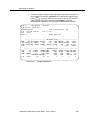
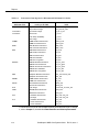
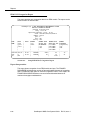
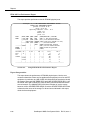
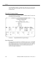
Reports ■ DISCARDED FRAMES, - >Bc+Be, -By Network - The total number of frames discarded because they exceeded the configured maximum throughput [the sum of the committed burst size (Bc) and excessive burst size (Be)] are shown on the first line in the FRM-M2 report. The second line of the FRM-M2 report shows the number of frames discarded because they were corrupted, incomplete or the module had no available buffers. ■ FAILS CONT - The number of unsuccessful connection attempts due to contention. This means that there were no free ports into this receiving group, and, thus, no available access to host, printer, and other services. ■ FAILS OTHER - The number of unsuccessful connection attempts due to reasons other than FAILS CONT. For example, when the service address accessing this group is out of service, or the host has crashed. ■ FAILS SEC - The number of unsuccessful connection attempts due to closed user group security. ■ FAILS TOTAL - The number of unsuccessful connection attempts due to reasons other than contention or closed user group security. These call failures include components being out of service (for example, the service address is out of service), hardware or software component failures (for example, the host has crashed), routing errors (for example, there is a loop or dead end in the network), or other (unknown) reasons. ■ FAR END, -%Err Free Seconds, -Line Errored Seconds, - Code Viol (FE BEr for E1), -Errored Seconds, - Severe Err Seconds, - Sev Err Frame Seconds, - Frame Slip Seconds - This column in the FRM Facility and the FRM-M2 Port Performance Reports displays the number of each of the listed error counts. ■ FIFO INTRPT - These are HALF FULL FIFO INTERRUPTS. It represents the number of times the FIFO reached the half full state during the interval. ■ FRAME FORMAT - the format of the incoming frames: esf, crc4-cept, etc. ■ FRAMES, -pk rcv, -pk xmt, -rcv, - xmt - For ports, the number of frames output to the line. ■ FRAMES, -rcv, -xmit - For DLCI, this field provides the total number of frames received and transmitted on the DLCI. ■ FRAMES, -rej rcv, -rej xmit - The number of times the remote FRM sent a reject (-rej rcv: first line) indicating it had to discard corrupted data, detected missing data, or had no available buffers. Or, the number of times the FRM had to discard data received (-rej xmit: second line) because it was corrupted, data was missing, or no buffers were available on the module. ■ FRAME BYTES - Total bytes in level 2 frames received from and transmitted to the port. StarKeeper II NMS Core System Guide R10.0, Issue 1 6-13 Reports 6-14 ■ FRAMES DISCARDED (congestion), -rcv, -xmt - The number of received (first line) or transmitted (second line) frames discarded because of insufficient buffer space or enforced congestion control. ■ FRAMES WITH CONGESTION BIT SET, -rcv FECN, -xmt FECN, -rcv BECN, -xmt BECN - The number of frames received with the congestion bit set for forward explicit congestion notification (FECN) or for backward explicit congestion notification (BECN) are indicated on the first and third lines, respectively. The second and fourth lines indicate the number of frames transmitted with the congestion bit set for FECN or BECN, respectively. ■ FRAMES WITH DE BIT SET BY NETWORK, -rcv, -xmt - The total number of frames received (first line) or transmitted (second line) with the discard eligibility (DE) bit set by the network. ■ FRAMES WITH DE BIT SET BY MODULE - The total number of frames with the DE bit set by the FRM or FRM-M2 module. ■ FROM DK ERRORS - for multiplexer reports The number of intervals (3.2 seconds) in which data blocks containing errors were received by the specified multiplexer port. ■ FROM DK TRAFFIC - for multiplexer reports The number of intervals (3.2 seconds) in which one or more characters of traffic traveled from the node to the specified multiplexer port. ■ FROM NODE BYTES - The number of bytes transmitted by the node's trunk module. Byte count includes user data and overhead. ■ FROM NODE PACKETS - The number of packets coming into the module from the backplane. It is the sum of in-service packet counts. ■ GROUP - The trunk group name to which this trunk belongs. ■ IDLE (%) - The percentage of time the module was idle, averaged over the interval. ■ INTRPTS - The number of half FIFO interrupts (X.75 module). ■ INVTVL also INTERVAL - Same as REPT INTVL. ■ LINK PAR ERR - The number of concentrator link parity error indicators. ■ LTYPE, SPEED - Displays (on the first line) the type of link or LIM (SWT or SFT); and shows the bps rate of the trunk (on the second line). ■ MIN IDLE - The minimum module CPU idle time percentage recorded during the interval; calculated over 5 minutes. ■ MOD - The number of the module (slot number) being reported on. ■ MOD # - for multiplexer reports Backplane link module address; SAMML and SAMDL includes port number. ■ MODULE ADDRESS also MOD ADD - The backplane address (slot number) of the module being reported on. StarKeeper II NMS Core System Guide R10.0, Issue 1 Reports ■ MOD ADDR.PORT - A two-part entry for the module being reported on (the slot number) and the port number, separated by a dot. ■ MOD ADDR.PORT,SPEED - A two-line entry. The first line is for the module being reported on (the slot number) and the port number (separated by a dot); the second line shows the module's rated speed (in bps). ■ MOD TYPE, MOD ADDR - for multiplexer reports - The module type and address being reported on. Module types are: AMUX64, AMUX504, SAM64, SAM504. Module address is: link address/board.port; for example, 18/2.3. ■ MOD TYPE,TRK TYPE - for multiplexer reports The multiplexer type and the type of trunk connected to the multiplexer. Module types are SAM64 and SAM504. Trunk types are HS, T1, SAMML, SAMDL, and SAMSL. ■ MSGS TOTAL - The total number of messages received from and transmitted to the port. ■ NAME,TYPE,SPEED - This displays the trunk name, with the trunk type listed below it, and the trunk speed listed below that. ■ NEAR END, -%Err Free Seconds, -Line Errored Seconds, - Code Viol (FE BEr for E1), -Errored Seconds, - Severe Err Seconds, - Sev Err Frame Seconds, - Frame Slip Seconds - This column in the FRM Facility and the FRM-M2 Port Performance Reports displays the number of each of the listed error counts. ■ NEAR END AIS SECS - The total time in seconds during which an incoming alarm indication signal (AIS) was present. ■ NEAR END BER6 SECS - The total time in seconds during which an incoming ber6 (two or more CRC4 errors detected in a one-second interval) was present. ■ NEAR END LINE CODE VIOL - The total number of non-valid bipolar line code violations encountered in the report interval. ■ NEAR END LINE SEVERE ERRED SECS - A count of the number of seconds with 16 or more line code violations. ■ NEAR END UNAVAIL SECS - The total time in seconds the service was unavailable on the FRM facility or FRM-M2 physical port during the report interval. ■ NET/DNIC, AREA/SR, EXCH/SA, NODE - The full node name as used by StarKeeper II NMS. ■ NODE or NODE NAME - The name of the node being reported on as known by StarKeeper II NMS, in the four-level mnemonic/numeric address format. ■ NODE PAR ERR - The number of node link parity error indicators. ■ NODE1 - The full name of one of this trunk's end nodes. ■ NODE2 - The full name of the other end node for this trunk. StarKeeper II NMS Core System Guide R10.0, Issue 1 6-15 Reports 6-16 ■ OVERFLOWS, -fm bckpl, -to bckpl - The rate at which information arriving at the FRM-M2 from the backplane (fm bckpl) or sent to the backplane (to bckpl) exceeded the rate at which information could be processed by the module. ■ PACKETS, -fm node, -to node also PACKETS, -recv, trans - The total number of packets that have been sent to the module from the node's backplane (first line) and the total number of packets that have been sent from the module to the node's backplane (second line). ■ PACKETS FROM (TO) BUS - The number of packets received from and going to the node backplane (bus). ■ PACKETS FROM (TO) NODE - The number of packets received from and going to the node backplane, through the module. ■ PACKETS RECEIVED - The number of packets received from the node and sent to the module. ■ PACKETS TRANSMITTED - The number of packets sent from the module to the node. ■ PKTS FROM - for concentrator reports The number of packets sent from the concentrator (to the node) during the report interval. ■ PKTS TO - for concentrator reports The number of packets sent to the concentrator (from the node) during the report interval. ■ PARITY ERRORS also PAR ERR - The number of node backplane envelopes discarded due to a parity error. ■ PEAK CONNECTIONS also PEAK CONN - The maximum number of all simultaneous connections (switched and non-switched) that occurred during the report interval. When both peaks and averages are requested, the data in parentheses contain the averages. ■ % AVG BUSY, recv, -trans - The average percent bandwidth used in a particular direction for that port. The first line is receive; the second line is transmit. ■ % AVG MAIN UTIL or % AVG MAIN UTILIZATION - The average percent utilization of the main processors over the measurement interval. ■ % BUSY - The percentage of time the module was busy, averaged over the hour. It is calculated by subtracting the average % IDLE TIME (coming from the node) from 100%. Another way of expressing this is as the average CPU busy time during the hour. ■ % CHAN UTIL - The number of peak connections divided by the number of in-service channels in a group. ■ %IO BOARD UTIL, -pk, -avg - The peak and average utilization of the FRM I/O board over the measurement interval. StarKeeper II NMS Core System Guide R10.0, Issue 1 Reports ■ % MIN IDLE - The percentage of idle time is saved for each 8-minute interval; the minimum idle time recorded for the reporting interval is then displayed. ■ % OVHD BYTE - The percentage of overhead (nondata) bytes ■ % PEAK BUSY, -recv, -trans - The peak percent bandwidth used in a particular direction for that port. The first line is receive; the second line is transmit. ■ % PEAK MAIN UTIL or %PEAK MAIN UTILIZATION - The percent utilization of the main processors over a five-minute peak interval. ■ % PEAK UTIL (FROM DK) - for multiplexer reports The peak utilization of the link. It is the traffic received divided by the line capacity, at peak times during the interval. ■ % PEAK UTIL (TO DK) - for multiplexer reports The peak utilization of the link. It is the traffic transmitted divided by the line capacity, at peak times during the interval. ■ % PORT UTIL - The number of peak connections divided by the number of in-service ports in a group. ■ % TRK UTIL (FROM DK) - for multiplexer reports The average utilization of the link. It is the traffic received divided by the line capacity during the interval. ■ % TRK UTIL (TO DK) - for multiplexer reports The average utilization of the link. It is the traffic transmitted divided by the line capacity during the interval. ■ % UTIL, -pk rcv, -pk xmt, rcv, xmt - The total bytes received or transmitted on the line divided by the speed of the line (or, the bandwidth used) in either direction during the measurement interval. ■ % UTIL,-recv,-trans also % UTIL, -rcv, -xmt - The average trunk utilization over the interval; the number of bytes divided by trunk capacity—in transmit and receive directions. Percentages are on two lines: first line is receive and second line is transmit. Byte counts are based on all data collected. ■ % UTIL,-recv,-trans - for concentrator reports Link average utilization: This is the number of packets sent and received divided by link capacity. ■ PORT - The port being reported on. ■ PORT SPEED - The speed (in bps) for which the port was configured (not necessarily the speed at which the port is running). ■ PORT UTIL REC% - The percentage of the characters received by the port divided by the port capacity, during the interval. ■ PORT UTIL TRANS% - The percentage of the characters transmitted by the port divided by the port capacity, during the interval. ■ RCV MSGS - The number of messages received from the device. StarKeeper II NMS Core System Guide R10.0, Issue 1 6-17 Reports 6-18 ■ RCVR ABORTS - The number of frames discarded by the node due to receiving an abort sequence from the port. It represents the total number of frames discarded from all aborts during the interval for this port. ■ RCVR CRC - The number of frames that contain corrupted data (receiver crc errors). ■ RCVR OVRN - The number of receiver overruns; this occurs when the module cannot keep up with the incoming data. ■ RECV GROUP - The name of the receiving or two-way group for the reported connection data. ■ RECEIVER, -overruns - The number of receiver overruns that occurred on the facility (FRM) or virtual port (FRM-M2) during the measurement interval. An overrun occurs when frames are received faster than they are stored and forwarded because the module processor is too busy. ■ RECEIVER, -bad frames - Same as RCVR CRC. ■ REJECTS RECEIVED - The number of times the remote end had to discard data due to either data corruption, or the remote module had no available buffers. ■ REJ FRAMES - The number of transmitted/received "Rejected" frames. A rejected frame is used by an X.75 module to request retransmission of I frames starting with the frame numbered N(R). I frames numbered [N(R)-1] and below are acknowledged. ■ REPT INTVL - Start and end time of the reporting interval. ■ RNR (Received Not Ready) FRAMES - The number of transmitted/ received RNR frames. RNR frames are used by an X.75 module to indicate a busy condition; that is, the temporary inability to accept additional incoming I frames. ■ SPEED - Same as PORT SPEED. ■ TERM NO. - The terminal number for each device off the port. ■ TO DK RETRAN - for multiplexer reports The number of intervals (3.2 seconds) that the node required the multiplexer to retransmit a block (a subset of packets). ■ TO DK TRAFFIC - for multiplexer reports The number of intervals (3.2 seconds) in which one or more characters of traffic traveled from the specified multiplexer port to the node. ■ TO NODE BYTES - The estimated number of bytes received at the node's trunk module. Byte count includes all data. ■ TO NODE PACKETS - The number of packets going out of the module to the backplane. It is the sum of in-service packet counts. StarKeeper II NMS Core System Guide R10.0, Issue 1 Reports ■ TOTAL BYTES (FROM DK) - for multiplexer reports The total number of bytes sent out to the multiplexer (from the node). ■ TOTAL BYTES (TO DK) - for multiplexer reports The total number of bytes sent to the node from the multiplexer. ■ TOTAL BYTES RECEIVED - The number of bytes received from the external host or device. ■ TOTAL BYTES TRANSMIT - The number of bytes transmitted to the external host or device. ■ TOTAL RCVR ABORTS - The number of receiver aborts. See RCVR ABORTS. ■ TOTAL RECEIVER OVERRUN - The number of receiver overruns. This occurs when the module cannot keep up with the incoming data. See RCVR OVRN. ■ TOTAL TRANS UNDRUN - The number of frames aborted by the port. ■ TRAN MSGS - The number of messages transmitted to the device. ■ TRANS UNDRUN OTHER - The number of transmission underruns due to conditions other than pipelining. ■ TRANS UNDRUN PIPELN - The number of transmission underruns due to pipelining. ■ TRUNK NAME - The name of the trunk being reported on. ■ TRUNK TYPE - The type of trunk being reported on. ■ USART ERRORS - for multiplexer reports The number of intervals (3.2 seconds) in which the USART associated with the specified multiplexer port had either an overflow, parity, or framing error. ■ USER BYTES - Total user data bytes received from and transmitted to the port. StarKeeper II NMS Core System Guide R10.0, Issue 1 6-19 Reports Getting FRM and FRM-M2 Performance Reports Using sched_report With the sched_report command, you can schedule FRM and FRM-M2 performance reports to be run at a particular time. By choice of options, you can specify the report information needed and when the report should be generated. The options in this command may be entered in any order, and the sched_report command can be run in real time if the set date (-sd) and set time (-st) options are omitted. The command allows you to view scheduled requests (sched_report -l) by job id and cancel pending requests (sched_report -r <job_id>). Continuous use of sched_report will lead to ever-growing log files in the directory $HOME/sched_scripts, or, when running the command in real time, in the directory /tmp. Users must clean up these log files periodically. It is recommended that you first execute the sched_report command in real time before entering the command for later execution. Because of the number and types of options that may be specified with this command, running it first can eliminate typographical and syntax errors. This will ensure that scheduled reports actually run when scheduled. The best approach is to enter the command as a shell script, and once it has run properly in real time, edit the script to add the date and time information. Refer to the online help for the sched_report command for complete details of syntax and allowed arguments. 6-20 StarKeeper II NMS Core System Guide R10.0, Issue 1 Reports Bisynchronous Device Usage Report This report provides usage information for BSC3270 modules. Significant items include the numbers of bytes and messages received from and transmitted to the port, numbers of messages received from and transmitted to the device, and the number of abnormal messages. StarKeeper (R) II NMS PERFORMANCE MEASUREMENTS SYSTEM BISYNC DEVICE USAGE REPORT printed: 01-02-98 14:46 daily: 01-01-98 reporting intervals: 00:00 - 11:59 interval length: 1-hour node type:BNS-2000 modules: all NET/DNIC| MOD| REPORT| BYTES| MSGS|| CONT| TERM| RCV| TRAN| ABNORM AREA/SR | PORT| INTRVL| TOTAL| TOTAL|| UNIT| NO.| MSGS| MSGS| STATUS EXCH/SA | | | | || | | | | SENSE NODE | | | | || | | | | ------------------------------------------------------------------------------national|25.1 | 11:00| 5609270| 185435|| | | | | east | | | | || | | | | garden | | | | || | | | | node20 | | | | || | | | | ------------------------------------------------------------------------------| | | | || 2| 1| 84| 58| 84 ------------------------------------------------------------------------------| | | | || 2| 2| 95| 49| 95 ------------------------------------------------------------------------------| | | | || 2| 3| 67| 96| 67 ------------------------------------------------------------------------------| | | | || 2| 4| 94| 69| 94 ------------------------------------------------------------------------------| | | | || 2| 5| 01| 20| 01 ------------------------------------------------------------------------------- Screen 6-2. Sample Bisynchronous Device Usage Report Report Interpretation This report shows the control unit and terminal measurements for bisynchronous service. It shows a level of detail beyond the port level, which is shown in the Bisynchronous Module Performance Report. This report is useful in interpreting line problems found in the Bisynchronous Module Performance Report. For example, if there is too much traffic for a port, this report will show which control units and terminals are responsible for the increased traffic. The RCV MSGS and TRAN MSGS show the traffic on the line between the port and the device. The ABNORM STATUS SENSE is an error indicator for the line. StarKeeper II NMS Core System Guide R10.0, Issue 1 6-21 Reports Bisynchronous Module Performance Report This report provides performance information for BSC3270 modules. Significant items include the numbers of packets to and from the node, the idle time for each module, and the utilization of each port. StarKeeper (R) II NMS PERFORMANCE MEASUREMENTS SYSTEM BISYNC MODULE PERFORMANCE REPORT printed: 01-02-98 14:46 daily: 01-01-98 reporting intervals: 00:00 - 11:59 interval length: 1-hour node type:BNS-2000 trunks: all NET/DNIC| MOD| REPORT| IDLE| PKTS| PKTS|| PORT| UTIL| ABNORM|| BUFFERS AREA/SR | | INTRVL| (%)| FROM| TO|| | (%)| EOT|| NOT EXCH/SA | | | | NODE| NODE|| | -recv| || AVAIL NODE | | | | | || |-trans| || ------------------------------------------------------------------------------national| 25| 11:00| 99| 15| 24|| | | || 0 east | | | | | || | | || forest | | | | | || | | || node22 | | | | | || | | || ------------------------------------------------------------------------------| | | | | || 1| 0| 12543|| 48593 ------------------------------------------------------------------------------- Screen 6-3. Sample Bisynchronous Module Performance Report Report Interpretation This report shows the usage and performance of the Bisynchronous module in relation to the node backplane. It also shows the usage of the ports in relation to the outgoing lines. The purpose of this report is to help identify and troubleshoot problems in bisynchronous service, whether caused by the module, port, or the line leading out of the port. A value of % IDLE that is higher or lower than average should be checked. A low % IDLE can indicate that the module is not being used, either because there is no user-initiated traffic or because there is a problem on the line side. The % IDLE value can be high with no adverse effect on performance. The error counts, however, do indicate a problem between the module and the backplane. That problem could be too much traffic for the module, given its location and the node it is in; or a malfunctioning module. BUFFER NOT AVAIL may indicate that incoming traffic is exceeding the capacity of the module. 6-22 StarKeeper II NMS Core System Guide R10.0, Issue 1 Reports The key field in this report is the % UTIL for the port. Port utilization is similar to trunk utilization. The port utilization is the average value for that interval, and is calculated by dividing the traffic by the capacity. A general guideline is that average port utilization should not exceed 70%, not because of the port itself but because of the transmission facility to which it is connected. An average below 70% means that the peak utilization should be safely under 100%. StarKeeper II NMS Core System Guide R10.0, Issue 1 6-23 Reports Concentrator Usage Report This report contains measurements for SFT and SWT trunks used to link supported concentrators to a node, as well as error counts for both ends of the link. It is very sensitive to correct user input on concentrator configuration in the configuration database. The data are sorted first by end node name, then by concentrator name, and finally by report interval. StarKeeper (R) II NMS PERFORMANCE MEASUREMENTS SYSTEM CONCENTRATOR USAGE REPORT printed: 01-02-98 14:46 daily: 01-01-98 reporting intervals: 00:00 - 11:59 interval length: 1-hour node type:BNS-2000 concentrators: all NET/DNIC|CONC ADD|LTYPE |REPT |% UTIL| PKTS TO| PKTS FROM| NODE| LINK AREA/SR |NAME |SPEED |INTVL| -recv| | | PAR ERR| PAR ERR EXCH/SA |TYPE | | |-trans| | | | NODE | | | | | | | | ------------------------------------------------------------------------------national|1 |SFT |11:00| 90 | 124611173| 123224226| 10 | 1 west |conc11 |8.64 |16:59| 88 | | | | 957 |FRS | | | | | | | node20 | | | | | | | | ------------------------------------------------------------------------------| | |15:00| 16 | 21111111| 586211| 28 | 4 | | |20:59| 6 | | | | ------------------------------------------------------------------------------national|130 |SFT |11:00| 5 | 936| 52341| 0 | 8 west |conc110 |8.64 |16:59| 20 | | | | 957 |CCOM | | | | | | | node20 | | | | | | | | Screen 6-4. Sample Concentrator Usage Report Report Interpretation This report shows the usage and performance of the link that connects the concentrator to the node. It is similar to the Trunk Usage Report because trunks and links are both transmission facilities. Like the Trunk Usage Report, the key field is % UTIL, which represents how much of the physical link is being used. The % UTIL is the average utilization of the link during the interval. A general guideline is that average link utilization should not exceed 70%. The error counts indicate the health of the link module in the node backplane. Increased error counts may indicate problems in the link module or the physical trunk. Error counts may or not be related to the % UTIL. For example, high usage and several errors can indicate that the link module is retransmitting and thereby creating traffic. 6-24 StarKeeper II NMS Core System Guide R10.0, Issue 1 Reports If a value in the % UTIL field cannot be explained by usage or errors, it is possible that the configuration information (particularly the link speed) was entered incorrectly in the database. The report uses the speed of the link from the database in its calculations. CPMML Module Performance Report This report provides module-level usage and performance measurements for a Computer Port Module - Multiport-Link (CPMML). The first columns (% BUSY, FROM NODE PACKETS, and TO NODE PACKETS) show the usage of the module and the last columns (PARITY ERRORS, CHANNEL ERRORS) show the performance of the module. Usage is a measure of the traffic, and performance is a measure of errors. Reports are available on a module or port basis, and at a frequency of daily, weekly, or monthly. Below is a sample daily CPMML module performance report. (The next section describes the CPMML port performance report. StarKeeper (R) II NMS PERFORMANCE MEASUREMENTS SYSTEM CPMML MODULE PERFORMANCE REPORT printed: 01-02-98 14:46 daily: 01-01-98 reporting intervals: 00:00 - 11:59 node type:BNS-2000 nodes: all modules: all NET/DNIC|MODULE |REPT | % |FROM NODE |TO NODE |PARITY |CHANNEL AREA/SR |ADDRESS |INTVL | BUSY |PACKETS |PACKETS |ERRORS |ERRORS EXCH/SA | | | | | | | NODE | | | | | | | ------------------------------------------------------------------------national|10 | 9:00 | 10% | 88 | 36 | 0 | 0 west | | 9:59 | | | | | 957 | | | | | | | node20 | | | | | | | ------------------------------------------------------------------------| | 10:00 | 43% | 283 | 663 | 0 | 0 | | 10:59 | | | | | Screen 6-5. Sample Daily CPMML Module Performance Report Report Interpretation The CPMML module can be in a slot on the node's backplane or in a slot in a concentrator. For weekly and monthly reports you can request peak values and/or averages. If both are requested, the peaks are listed first and the averages are shown in parentheses under the peaks. Usage and performance measurements for a module may or may not be related. Usage is a measure of the traffic and performance StarKeeper II NMS Core System Guide R10.0, Issue 1 6-25 Reports is a measure of errors—usually hardware related. These two types of measurements can complement each other. For example, high usage and several errors can indicate a module that is retransmitting and thereby creating traffic. The report shows the usage and performance of the CPMML module in relation to the node backplane. Use the report to help troubleshoot problems that are detected in other reports, such as port utilization reports. For example, problems with port utilization could be caused by an overworked (high usage or too much traffic) module. This report is also useful for monitoring the performance of newly installed or suspect CPMML modules. The % BUSY value can be high with no adverse affect on performance. The error counts, however, do indicate problems between the module and the backplane. A channel error may be caused by faulty module software or hardware. A parity error may be caused by faulty hardware in the node or inserting a circuit pack in the backplane. 6-26 StarKeeper II NMS Core System Guide R10.0, Issue 1 Reports CPMML Port Performance Report This report provides port-level usage and performance measurements for Computer Port Module - Multi-Link (CPMML) modules. The first columns (%UTIL and TOTAL BYTES, in each direction) shows the usage of the port. The last columns (RCVR ABORTS, CRC ERRORS) show the performance of the port and/or wire. Below is a sample, daily CPMML port performance report sorted by port address; the report is also available sorted by report interval. (The previous section describes the CPMML module performance report.) StarKeeper (R) II NMS PERFORMANCE MEASUREMENTS SYSTEM CPMML PORT PERFORMANCE REPORT printed: 01-02-98 14:46 daily: 01-01-98 reporting intervals: 00:00 - 11:59 node type:BNS-2000 nodes: all modules: 3 ports: all sort: address NET/DNIC|MOD |PORT |REPT | %UTIL|TOTAL BYTES |RCVR |CRC AREA/SR |ADDR.|SPEED|INTVL|-recv |-recv |ABORTS |ERRORS EXCH/SA |PORT | | |-trans|-trans | | NODE | | | | | | | -----------------------------------------------------------------------national|12.1 | 9600| 2:00| | R 76 | 1 | 0 west | | | 2:59| | T 788 | 12 | 9 957 | | | | | | | node1 | | | | | | | -----------------------------------------------------------------------| | | 3:00| | R 889 | 1 | 0 | | | 3:59| | T 788 | 2 | 9 -----------------------------------------------------------------------| | | 4:00| | R 1234 | 21 | 0 | | | 4:59| | T 9788 | 12 | 9 ------------------------------------------------------------------------ Screen 6-6. Sample CPMML Port Performance Report (Module Address) Report Interpretation This report shows the usage and performance of the CPMML ports in relation to the user endpoints. The purpose of this report is to help identify and troubleshoot problems. This report can also be used to identify problems with the transmission facility (for example, a wire). For example, RCVR ABORTS can be due to noise on the wire or to the remote end being overloaded. CRC ERRORS indicate problems with the wire. StarKeeper II NMS Core System Guide R10.0, Issue 1 6-27 Reports DKAP Channel Performance Report This report provides channel-level usage and performance measurements for Datakit Applications Processor (DKAP) modules. The (TOTAL BYTES, in each direction column) shows the usage of the channel. The BUFFER NOT AVAIL column shows the performance of the channel and/or wire. Below is a sample, daily DKAP channel performance report sorted by channel address; it is also available sorted by report interval. (The previous section describes the DKAP module performance report.) StarKeeper (R) II NMS PERFORMANCE MEASUREMENTS SYSTEM DKAP CHANNEL PERFORMANCE REPORT printed: 01-02-98 14:46 daily: 01-01-98 reporting intervals: 00:00 - 11:59 node type:BNS-2000 nodes: all modules: all sort: interval NET/DNIC|MOD |REPT |TOTAL BYTES | BUFFER AREA/SR |CHANNEL |INTVL|-recv | NOT EXCH/SA | | |-trans | AVAIL NODE | | | | -------------------------------------------------------------------national| 27 | 6:00| R 311 | 0 west | 1 | 6:59| T 278 | 957 | | | | node20 | | | | -------------------------------------------------------------------| | 7:00| R 789 | 0 | | 7:59| T 964 | -------------------------------------------------------------------| | 8:00| R 278436 | 4 | | 8:59| T 346069 | -------------------------------------------------------------------| | 9:00| R 857804 | 11 | | 9:59| T 838963 | Screen 6-7. Sample DKAP Channel Performance Report (Channel Address) Report Interpretation This report shows the usage and performance of the DKAP channels in relation to the user endpoints. The purpose of this report is to help troubleshoot problems that are detected in other reports, such as the DKAP Module Performance Report. This report can also be used to identify problems with the transmission facility (for example, a wire). BUFFER NOT AVAIL indicates the incoming traffic is exceeding the capacity of the channel. 6-28 StarKeeper II NMS Core System Guide R10.0, Issue 1 Reports DKAP Module Performance Report This report provides module-level usage and performance measurements for a Datakit Applications Processor (DKAP) module. The first columns (% BUSY, FROM NODE PACKETS, and TO NODE PACKETS) show the usage of the module and the last columns (FIFO INTRPT, BUFFER NOT AVAIL) show the performance of the module. Reports are available on a module or port basis, and at a frequency of daily, weekly, or monthly. Below is a sample daily DKAP module performance report. (The next section describes the DKAP channel performance report.) StarKeeper (R) II NMS PERFORMANCE MEASUREMENTS SYSTEM DKAP MODULE PERFORMANCE REPORT printed: 01-02-98 14:46 daily: 01-01-98 reporting intervals: 00:00 - 11:59 node type:BNS-2000 nodes: all modules: all NET/DNIC|MOD |REPT |%BUSY| FROM NODE| TO NODE| FIFO| BUFFER AREA/SR |ADDR |INTVL | | PACKETS| PACKETS| INTRPT| NOT EXCH/SA | | | | | | | AVAIL NODE | | | | | | | ----------------------------------------------------------------------national|11 | 9:00 | 11% | 588 | 336 | 0 | 0 west | | 9:59 | | | | | 957 | | | | | | | node20 | | | | | | | ----------------------------------------------------------------------| | 10:00 | 10% | 283 | 663 | 0 | 0 | | 10:59 | | | | | Screen 6-8. Sample Daily DKAP Module Performance Report Report Interpretation For weekly and monthly reports you can request peak values and/or averages. If both are requested, the peaks are listed first and the averages are shown in parentheses under the peaks. Usage and performance measurements for a module may or may not be related. Usage is a measure of the traffic and performance is a measure of errors—usually hardware related. These two types of measurements can complement each other. For example, high usage and several errors can indicate a module that is retransmitting and thereby creating traffic. StarKeeper II NMS Core System Guide R10.0, Issue 1 6-29 Reports The report shows the usage and performance of the DKAP module in relation to the node backplane. Use the report to help troubleshoot problems that are detected in other reports, such as port utilization reports. For example, problems with port utilization could be caused by an overworked (high usage or too much traffic) module. This report is useful for monitoring the performance of newly installed or suspect DKAP modules. The % BUSY value can be high with no adverse affect on performance. The error counts, however, do indicate problems between the module and the backplane. Those problems could be too much traffic for the module, given its location and the node it is in; or a malfunctioning module. FIFO INTRPT indicates that the module is getting too busy. BUFFER NOT AVAIL indicates incoming traffic is exceeding the capacity of the module. FRM and FRM-M2 Performance Reports NOTE: FRM and FRM-M2 performance reports can be generated by using either the report or sched_report command. This set of ten reports provides performance data for frame relay modules FRM and FRM-M2. A listing of available reports is given in Table 6-1. Example of these reports are presented in the following screens with the FRM reports shown first followed by the FRM-M2 reports. 6-30 StarKeeper II NMS Core System Guide R10.0, Issue 1 Reports FRM Module Performance Report This report provides module performance data for an FRM module. StarKeeper (R) II NMS PERFORMANCE MEASUREMENTS SYSTEM FRM MODULE PERFORMANCE REPORT printed: 01-02-98 14:46 Daily: 01-01-98 reporting intervals: 00:00 - 11:59 nodes: all module: all NODE NAME |ADDR |INTVL |%AVG MAIN |%PEAK MAIN | PACKETS |CONGESTION |-mod | |UTILIZATION|UTILIZATION | -fm node |-count | | | | | -to node |-seconds | | | | | ----------------------------------------------------------------------national| 20 | 16:00 | 72 | 80 | 7111858 | 0 east | | 16:59 | | | 694 | 0 957 | | | | | | node20 | | | | | | ----------------------------------------------------------------------|72/2 | 16:00 | 30 | 54 | 9234681 | | | 16:59 | | | 2461 | | | | | | | | | | | | | ----------------------------------------------------------------------national| 22 | 16:00 | 39 | 53 | 8643296 | east | | 16:59 | | | 12668 | 957 | | | | | | node21 | | | | | | ------------------------------------------------------------------------ Screen 6-9. Sample FRM Module Performance Report Report Interpretation This report shows the performance of FRM modules. The percentage values found in the %AVG MAIN UTILIZATION and %PEAK MAIN UTILIZATION fields can be used to determine if the module is being used at its full capacity. The CONGESTION and PACKET fields give an indication of the traffic flow on the backplane. If these values are being used to determine if the module, port, or virtual circuit is overloaded or congested, they should be used in conjunction with the DISCARDED FRAMES statistics in the FRM DLCI Utilization Report to determine if the buffer space is adequate for the traffic. In particular, the CONGESTION field gives an indication of severe congestion and affects all ports on the module. A high CONGESTION count may mean that the network should be re-engineered to reduce the load on the module. Use the CONGESTION field in conjunction with the %AVG MAIN UTILIZATION and % PEAK MAIN UTILIZATION fields to determine if the module is overloaded. StarKeeper II NMS Core System Guide R10.0, Issue 1 6-31 Reports FRM Facility Performance Report This report provides performance data for an FRM facility. StarKeeper (R) II NMS PERFORMANCE MEASUREMENTS SYSTEM FRM FACILITY PERFORMANCE REPORT printed: 01-02-98 14:46 Daily: 01-01-98 reporting intervals: 00:00 - 11:59 nodes: all module: all NODE NAME |ADDR |%IO |NEAR |NEAR |NEAR |NEAR |NEAR END | FAR END |-mod |BOARD|END |END |END |END |-% Err Free Seconds | |UTIL |UN- |LINE |LINE |AIS |-Line Erreored Seconds | |-pk |AVAIL|CODE |SEVERE|SECS |-Code Viol(FE BEr if crc4) |-----|-avg |SECS |VIOL |ERRED |-----|-Errored Seconds --------| | | | |SECS |NEAR |-Severed Err Seconds |INTVL| | | | |END |-Sev Err Frame Seconds FRAME | | | | | |BER6 |-Frame SlipSeconds FORMAT | | | | | |SECS | -------------------------------------------------------------------national| 20 | 26| 0 | 12 | 23| 0 | 100 | 100 east | | 12| | | | | 0 | 0 957 | | | | | |-----| 0 | 0 node20 |-----| | | | | N/A| 0 | 0 |16:00| | | | | | 0 | 0 --------|16:59| | | | | | 0 | 0 esf | | | | | | | 0 | 0 ------------------------------------------------------------------------ Screen 6-10. Sample FRM Facility Performance Report Report Interpretation This report shows the performance of FRM facilities. Use the error counters to determine if there are line problems at the facility or far end DTF equipment. In particular, the LINE CODE VIOL field should be checked to identify the cause of near-end LINE ERRD SECS and LINE SEVERE ERRD SECS. Use the CODE VIOL field to identify the cause of facility errored seconds and severe errored seconds. The UNAVAIL SECS field is an indication of service outage based on loss of signal (LOS) or SEVRE ERRD SECS. Check the SEVRE ERRD SECS field to determine the cause of the outage. For far-end errors indicated in this report, check the far-end equipment. 6-32 StarKeeper II NMS Core System Guide R10.0, Issue 1 Reports FRM Port Performance Report This report provides performance data for an FRM port. StarKeeper (R) II NMS PERFORMANCE MEASUREMENTS SYSTEM FRM PORT PERFORMANCE REPORT printed: 01-02-98 14:46 Daily: 01-01-98 reporting intervals: 10:00 - 10:59 node: national/east/957/node10 module: 123/12 port: 6 NODE MAME |ADDR |INTERVAL |%UTIL |BYTES |FRAMES |AVERAGE |-mod | |-pk rcv|-pk rcv |-pk rcv |FRAME SZ |-port |-----------|-pk xmt|-pk xmt |-pk xmt |-pk rcv | |RECEIVER |-rcv |-rcv |-rcv |-pk xmt |----- |-overuns |-xmt |-xmt |-xmt |-rcv |SPEED |-bad frms | | | |-xmt --------------------------------------------------------------------national|123/12| 10:00 | 37 | 5801923 | 6446 | 900 east | 6 | 10:59 | 23 | 22725260 | 15130 | 1502 957 | |-----------| 10 | 22924109 | 15156 | 1499 node10 |------| 0 | 39 | 12877413 | 8651 | 1488 | 9600 | 0 | | | | Screen 6-11. Sample FRM Port Performance Report Report Interpretation This report shows the performance of FRM ports. The RECEIVER-bad frms value represents the number of frames that the FRM received in the reporting interval that were faulty, i.e., frames that have one of the following problems: a non-integral number of octets, an aborted frame, or a bad frame check sequence (FCS). When the module receives a bad frame, it discards that frame. There are three possible causes of bad frames: a faulty access device, such as a router; transmission errors on the facilities; or a faulty module. If the RECEIVER-bad frms value is high, do the following to determine the cause of the problem: StarKeeper II NMS Core System Guide R10.0, Issue 1 6-33 Reports ■ Check the facility using the FRM Facility Performance Report. ■ Check the FRM configuration to ensure that the correct maximum frame size is being used. Run on-line diagnostics on the FRM to further isolate the problem. ■ Check the access device configuration to ensure that the correct maximum frame size is being used. Run diagnostics on the access device (where available) to further isolate the problem. ■ Check alarm messages for further information on faulty frames. The RECEIVER-overruns field shows the number of overruns that occurred on the port during the report interval. An overrun occurs when frames are received faster than they are stored and forwarded because the FRM processor is too busy. If the RECEIVER-overruns count is high, check the following: ■ AVERAGE FRAME SZ - a small average frame size could cause high processor utilization. ■ I/O board utilization - the I/O board may be too busy. ■ Hardware - if the frame size is large and the %UTIL is at a reasonable number, the problem may be bad hardware. Swap hardware or run diagnostics to check. If port or main processor utilization is high, check the AVERAGE FRAME SZ field, and if it is small, either the frame size should be increased or the amount of data decreased. Use the %UTIL fields to determine usage of the port during the interval. In conjunction with the FRM DLCI Utilization and FRM DLCI Congestion report statistics, this information can be used to determine if additional ports should be added, or if the current configuration is adequate for the traffic conditions. 6-34 StarKeeper II NMS Core System Guide R10.0, Issue 1 Reports FRM DLCI Utilization Report This report provides DLCI utilization data for an FRM module. The report can be sorted on a dlci or interval basis. StarKeeper (R) II NMS PERFORMANCE MEASUREMENTS SYSTEM FRM DLCI UTILIZATION REPORT printed: 01-02-98 14:46 Daily: 01-01-98 reporting intervals: 10:00 - 10:59 node: national/east/957/node 10 module: 123/12 port: 6 dlci: 1001 sort by: interval NODE NAME |ADDR | INTVL |FRAMES |BYTES |FRAMES WITH |DISCARDED |-mod | |-rcv |-rcv |DE BIT SET |FRAMES |-port | |-xmit |-xmit |BY MODULE |(>Bc+Be) |-dlci | |-rej rcv | | | | | |-rej xmit | | | -------------------------------------------------------------------------------national|123/12 | 10:00 | 2349713 | 22724109 | 838 | 23 east |6 | 10:59 | 2105691 | 40896000 | | 957 |1001 | | 1345 | | | node10 | | | 2461 | | | --------------------------------------------------------------------------------- Screen 6-12. Sample FRM DLCI Utilization Report Report Interpretation This report shows the DLCI usage for an FRM module and port. The DISCARDED FRAMES values indicate the number of times frames were discarded by the FRM module. Frames are discarded because the configured maximum throughput has been exceeded or because of either the unavailability of buffers or enforced congestion control. If the FRAMES-rej rcv field is high, check error counts and utilization levels along the path of the virtual circuit (particularly on trunks) and the DISCARDED FRAMES field (transmit direction) at the remote module to determine the cause of data discards. If the FRAMES-rej xmit field is high, check error counts along the path. Use the FRAMES WITH DE BIT SET field as an indication of whether the specified throughput is adequate. In addition to frames with the DE bit set, this field counts the ingress frames that exceed Bc but did not exceed the maximum configured throughput for the DLCI, Bc+Be. If a CIR is not configured for the DLCI, this field is not applicable. StarKeeper II NMS Core System Guide R10.0, Issue 1 6-35 Reports FRM DLCI Congestion Report This report provides port congestion data for an FRM module. The report can be sorted on a dlci or interval basis. StarKeeper (R) II NMS PERFORMANCE MEASUREMENTS SYSTEM FRM DLCI CONGESTION REPORT printed: 01-02-98 14:46 Daily: 01-01-98 reporting intervals: 10:00 - 10:59 node: national/east/957/node 10 module: 123/12 port: 6 dlci: 390 sort by: dlci NODE NAME |ADDR | INTVL |FRAMES |FRAMES WITH FRAMES WITH |FRAMES |-mod | |-rcv |DE BIT SET |CNGST BIT SET |DISCARDED |-port | |-xmit |BY NETWORK |-rcv FECN |(congestion) |-dlci | | |-rcv |-xmt FECN |-rcv | | | |-xmt |-rcv BECN |-xmt | | | | |-xmt BECN | -------------------------------------------------------------------------------national|123/12 | 10:00 | 2256820| 2396 | 23 | 10 east |6 | 10:59 | 2365932| 45 | 13 | 21 957 |390 | | | | 2145 | Screen 6-13. Sample FRM DLCI Congestion Report Report Interpretation This report shows congestion for an FRM module and port. The FRAMES DISCARDED field shows the number of frames discarded because of congestion, that is, insufficient buffer space or enforced congestion control. In this report, the FRAMES DISCARDED field does not count frames discarded because of maximum throughput considerations. 6-36 StarKeeper II NMS Core System Guide R10.0, Issue 1 Reports FRM-M2 Module Performance Report This report provides module performance data for an FRM-M2 module. StarKeeper (R) II NMS PERFORMANCE MEASUREMENTS SYSTEM FRM-M2 MODULE PERFORMANCE REPORT printed: 01-02-98 14:46 Daily: 01-01-98 reporting intervals: 16:00 - 16:59 nodes: all module: all NODE NAME |ADDR|INTVL|%AVG |%PEAK|PACKETS |CONGEST|OVERFLOWS |ATM SEGS |-mod| |MAIN |MAIN |-fm node |-cnt |-fm bckpl |-fm node | | |UTIL |UTIL |-to node |-secs |-to bckpl |-to node ----------------------------------------------------------------------national| 123|16:00| 57 | 63 | 431682 | 2 | 192 | 14 east | |16:59| | | 8009 | 15 | 78 | 111 957 | | | | | | | | node20 | | | | | | | | ----------------------------------------------------------------------|72 |16:00| 30 | 45 | 32714922| 0| 0 | 0 | |16:59| | | 4129| 0| 0 | 0 ----------------------------------------------------------------------national| 22 |16:00| 39 | 61 | 811299| 10| 8 | 196 east | |16:59| | | 982| 30| 120 | 41 957 | | | | | | | | node21 | | | | | | | | ------------------------------------------------------------------------ Screen 6-14. Sample FRM-M2 Module Performance Report Report Interpretation This report shows the performance of FRM-M2 modules. The percentage values found in the %AVG MAIN UTIL and %PEAK MAIN UTIL fields can be used to determine if the module is being used at its full capacity. The CONGEST, PACKET, ATM SEGS, and OVERFLOWS fields give an indication of the traffic flow through the buffer and on the backplane. If these values are being used to determine if the module is overloaded or congestion, they should be used in conjunction with the DISCARDED FRAMES statistics in the FRM-M2 DLCI Utilization Report to determine if the buffer space is adequate for the traffic. The OVERFLOWS fields give an indication of severe congestion on the module. If a high rate is reported, you may have to re-engineer the network to reduce the load on the module. In particular, the CONGESTION field gives an indication of severe congestion and affects all ports on the module. A high CONGESTION count may mean that the network should be re-engineered to reduce the load on the module. Use the CONGESTION field in conjunction with the %AVG MAIN UTIL and % PEAK MAIN UTIL fields to determine if the module is overloaded. StarKeeper II NMS Core System Guide R10.0, Issue 1 6-37 Reports FRM-M2 Port Performance Report This report provides performance data for FRM-M2 physical ports. StarKeeper (R) II NMS PERFORMANCE MEASUREMENTS SYSTEM FRM-M2 PORT PERFORMANCE REPORT printed: 01-02-98 14:46 Daily: 01-01-98 reporting intervals: 16:00 - 16:5 nodes: all module: all ports: all NODE NAME |ADDR |NEAR |NEAR |NEAR |NEAR|NEAR END | FAR END |-mod |END |END |END |END |-% Err Free Seconds |-port|UN- |LINE |LINE |AIS |-Line Erreored Seconds | |AVAIL|CODE |SEVERE |SECS|-Code Viol (FE BEr if crc4) |-----|SECS |VIOL |ERRED |----|-Errored Seconds | | | |SECS |NEAR|-Severed Err Seconds --------|INTVL| | | |END |-Sev Err Frame Seconds FRAME | | | | |BER6|-Frame Slip Seconds FORMAT | | | | |SECS| ----------------------------------------------------------------national| 20 | 0| 24 | 28| 2 | 91.2| 98.0 east | 11 | | | | | 3| 4 957 | | | | | | 409| 97 node20 |-----| | | |----| 38| 8 |16:00| | | | 0 | 24| 5 |16:59| | | | | 8| 3 | | | | | | 3| 4 -------------------------------------------------------------------- Screen 6-15. Sample FRM-M2 Port Performance Report Report Interpretation This report shows the performance of FRM-M2 physical ports. Use the error counters to determine if there are line problems at the physical port or far end DTF equipment. In particular, the LINE CODE VIOL field should be checked to identify the cause of near-end LINE ERRD SECS and LINE SEVERE ERRD SECS. Use the CODE VIOL field to identify the cause of facility errored seconds and severe errored seconds. The UNAVAIL SECS field is an indication of service outage based on LOS or SEVERE ERRD SECS. Check the SEVERE ERRD SECS field to determine the cause of the outage. For far-end errors indicated in this report, check the far-end equipment. 6-38 StarKeeper II NMS Core System Guide R10.0, Issue 1 Reports FRM-M2 Virtual Port Performance Report This report provides performance data for FRM-M2 virtual ports. StarKeeper (R) II NMS PERFORMANCE MEASUREMENTS SYSTEM FRM-M2 VIRTUAL PORT PERFORMANCE REPORT printed: 01-02-98 14:46 Daily: 01-01-98 reporting intervals: 10:00 - 10:59 node: national/east/957/node10 module: 123 port: 6 vport: 12 NODE MAME |ADDR |INTERVAL |%UTIL |BYTES |FRAMES |AVERAGE |CONGEST |-mod | |-pk rcv|-pk rcv |-pk rcv |FRAME SZ|-rcv cnt |-port |-----------|-pk xmt|-pk xmt |-pk xmt |-pk rcv |-xmt cnt |-vport|RECEIVER |-rcv |-rcv |-rcv |-pk xmt |-rcv secs |----- |-overuns |-xmt |-xmt |-xmt |-rcv |-xmt secs |SPEED |-bad frms | | | |-xmt | ------------------------------------------------------------------------------national|123 | 10:00 | 63 | 9613928 | 1924362 | 900 | 0 east | 6 | 10:59 | 81 | 2481119 | 892119 |1502 | 0 957 | 12 |-----------| 57 | 892003 | 3224681 |1399 | 0 node10 |------| 0 | 74 | 241026 | 540004 |1277 | 0 | 9600 | 0 | | | | | ------------------------------------------------------------------------------- Screen 6-16. Sample FRM-M2 Virtual Port Performance Report Report Interpretation This report shows the performance of FRM-M2 virtual ports.The RECEIVER-bad frms value represents the number of frames that the FRM-M2 received in the reporting interval that were faulty, i.e., frames that have one of the following problems: a non-integral number of octets, an aborted frame, or a bad FCS. When the module receives a bad frame, it discards that frame. There are three possible causes of bad frames: a faulty access device, such as a router, transmission errors on the facilities, or a faulty module. If the RECEIVER-bad frms value is high, do the following to determine the cause of the problem: ■ Check the facility using the FRM-M2 Physical Port Performance Report. ■ Check the FRM-M2 configuration to ensure that the correct maximum frame size is being used. Run on-line diagnostics on the FRM-M2 to further isolate the problem. StarKeeper II NMS Core System Guide R10.0, Issue 1 6-39 Reports ■ Check the access device configuration to ensure that the correct maximum frame size is being used. Run diagnostics on the access device (where available) to further isolate the problem. ■ Check alarm messages for further information on faulty frames. The RECEIVER-overruns field shows the number of overruns that occurred on the port during the report interval. An overrun occurs when frames are received faster than they are stored and forwarded because the FRM-M2 processor is too busy. If the RECEIVER-overruns count is high, check the following: ■ AVERAGE FRAME SZ - a small average frame size could cause high processor utilization. ■ I/O board utilization - the I/O board may be too busy. ■ Hardware - if the frame size is large and the %UTIL is at a reasonable number, the problem may be bad hardware. Swap hardware or run diagnostics to check. The CONGESTION field is an indication of severe congestion and may affect all ports (physical and virtual) on the module. Transmitter congestion usually indicates a speed mismatch (more data entering from the backplane than can be transmitted through the port). In this case, the port speed should be increased. Use the CONGESTION field in conjunction with the %UTIL field to determine usage if the virtual port is overloaded. 6-40 StarKeeper II NMS Core System Guide R10.0, Issue 1 Reports FRM-M2 DLCI Utilization Report This report provides port utilization data for an FRM-M2 module. The report can be sorted on a dlci or interval basis. StarKeeper (R) II NMS PERFORMANCE MEASUREMENTS SYSTEM FRM-M2 DLCI UTILIZATION REPORT printed: 01-02-98 14:46 Daily: 01-01-98 reporting intervals: 10:00 - 10:59 node: national/east/957/node 10 module: 123 port: 6 vport: 12 dlci: 1001 sort by: interval NODE NAME |ADDR | INTVL |FRAMES |BYTES |FRAMES WITH |DISCARDED |-mod | |-rcv |-rcv |DE BIT SET |FRAMES |-port | |-xmit |-xmit |BY MODULE |- >Bc+Be |-vport | | | | |- By Network |-dlci | | | | | -------------------------------------------------------------------------------national| 123 | 10:00 | 2339871 | 22724109 | 877 | 23 east | 6 | 10:59 | 2104468 | 40896000 | | 15 957 | 12 | | | | | node10 | 1001 | | | | | --------------------------------------------------------------------------------- Screen 6-17. Sample FRM-M2 DLCI Utilization Report Report Interpretation This report shows the DLCI congestion for an FRM-M2 module and port. The DISCARDED FRAMES values indicate the number of times frames were discarded by the FRM-M2 module. Frames are discarded because the configured maximum throughput has been exceeded or because of either the unavailability of buffers or enforced congestion control. These numbers can indicate an overloaded or congested module, port, or virtual circuit. Use these numbers in conjunction with traffic count statistics in the FRAMES and BYTES fields, along with the statistics in the FRM-M2 DLCI Congestion report and the FRM-M2 Port and Virtual Port Performance reports to determine if the module or port is overloaded or congested. Use the FRAMES WITH DE BIT SET field as an indication of whether the specified throughput is adequate. In addition to frames with the DE bit set, this field counts the ingress frames that exceed Bc but did not exceed the maximum configured throughput for the DLCI, Bc+Be. If a CIR is not configured for the DLCI, this field is not applicable. StarKeeper II NMS Core System Guide R10.0, Issue 1 6-41 Reports If the DISCARDED FRAMES - by Network field is high, check error counts at the remote module and along the path of the virtual circuit to determine the cause of the data discards. FRM-M2 DLCI Congestion Report This report provides port congestion data for an FRM-M2 module. The report can be sorted on a dlci or interval basis. StarKeeper (R) II NMS PERFORMANCE MEASUREMENTS SYSTEM FRM-M2 DLCI CONGESTION REPORT printed: 01-02-98 14:46 Daily: 01-01-98 reporting intervals: 10:00 - 10:59 node: national/east/957/node 10 module: 123 port: 6 vport: 12 dlci: 142 sort by: dlci NODE NAME |ADDR | INTVL |FRAMES |FRAMES WITH FRAMES WITH |FRAMES |-mod | |-rcv |DE BIT SET |CNGST BIT SET |DISCARDED |-port | |-xmit |BY NETWORK |-rcv FECN |(congestion) |-vport | | |-rcv |-xmt FECN |-rcv |-dlci | | |-xmt |-rcv BECN |-xxmt | | | | |-xmt BECN | -------------------------------------------------------------------------------national| 123 | 10:00 | 15156 | 2396 | 23 | 10 east | 6 | 10:59 | 8651 | 47 | 13 | 25 957 | 12 | | | | 2445 | node10 | 142 | | | | 27 | Screen 6-18. Sample FRM-M2 DLCI Congestion Report Report Interpretation This report shows the congestion for an FRM-M2 module and port. The FRAMES DISCARDED field shows the number of frames discarded because of congestion, that is, insufficient buffer space or enforced congestion control. In this report, the FRAMES DISCARDED field does not count frames discarded because of maximum throughput considerations. 6-42 StarKeeper II NMS Core System Guide R10.0, Issue 1 Reports Host Access Report Host Access Reports show connection data for each specified receiving group or two-way group. A receiving group contains the devices that only receive calls (for instance, ports or channels that connect to a host dial-out modem, or a printer). A two-way group can both receive and originate calls (for instance, a PC, a modem, or a host computer). It is called the Host Access Report because the most common use of the report is to display the number of calls going out from a node to a host computer. However, the report applies to all receiving groups, whether they access a host or not. Reports are available on a daily, weekly, or monthly basis. The example below is a monthly report. You can also request peak or average data or both; the example below shows the result of choosing both. StarKeeper (R) II NMS PERFORMANCE MEASUREMENTS SYSTEM HOST ACCESS REPORT printed: 01-02-98 14:46 daily: 01-01-98 reporting intervals: 00:00 - 11:59 interval length: 1-hour node type:BNS-2000 receiving groups: all NET/DNIC| RECV| REPORT| PEAK| % PORT| CALL| FAILS| FAILS| FAILS| FAILS AREA/SR | GROUP| INTRVL| CONN| UTIL| ATTMPT| TOTAL| CONT| SEC| OTHER EXCH/SA | | | | | | | | | NODE | | | | | | | | | ----------------------------------------------------------------------------national|gchecker | 10:00| 69| 15| 70| 0| 0| 0| 0 east | | | (19)| (15)| (20)| (0)| (0)| (0)| (0) 957 | | | | | | | | | node20 | | | | | | | | | ----------------------------------------------------------------------------| | 11:00| 169| 15| 90| 0| 0| 0| 0 | | | (39)| (15)| (33)| (0)| (0)| (0)| (0) Screen 6-19. Sample Host Access Report (Monthly) StarKeeper II NMS Core System Guide R10.0, Issue 1 6-43 Reports Report Interpretation The report is sorted in this order: first, by node name; second, by group name; and third, by reporting interval. You want to determine if the receiving groups are set up in the node in an optimal way; that is, to see if the number of ports assigned to a group is optimal. Determine port usage by reviewing the % PORT UTIL field. Ideally, % PORT UTIL is high and there are no failed attempts. A low percentage may indicate that too many ports are assigned to that group. High values in the FAILS CONT field indicate that not enough ports were assigned to that group. There may be accompanying end user response time delays as the number of call attempts may be higher along with the number of failures due to contention. All failed connection attempts are reported. FAILS SEC must be monitored to determine whether attempts to breach network security are being made. If the FAILS OTHER field is high, check to see if components are out of service, if there are network failures, or if the routing tables are correct. Resolving these problems should reduce the failures in this field. 6-44 StarKeeper II NMS Core System Guide R10.0, Issue 1 Reports Multiplexer Module Usage Report This report shows the usage and performance of the link that connects a Synchronous/ Asynchronous Multiplexer (SAM64 and SAM504) to the node. Measurements are from the Link Interface Module (LIM) on the node backplane. StarKeeper (R) II NMS PERFORMANCE MEASUREMENTS SYSTEM MULTIPLEXER MODULE USAGE REPORT printed: 01-02-98 14:46 daily: 01-01-98 reporting intervals: 00:00 - 11:59 interval length: 1-hour node type:BNS-2000 nodes: all <-------FROM DK------> <-------TO DK--------> MOD TYPE| REPT|MOD #| TOTAL | % | % | TOTAL | % | % | TO DK| FROM TRK TYPE|INTVL| | BYTES | TRK| PEAK| BYTES | TRK| PEAK|RETRAN| DK | | | | UTIL| UTIL| | UTIL| UTIL| | ERRS ------------------------------------------------------------------------------SAM/64 | 9:00|11.4 | 2529 | 1 | 2 | 2386 | 4 | 5 | 6 | 7 SAMML | 9:59| | | | | | | | | ------------------------------------------------------------------------------|10:00|11.4 | 21529 | 11 | 21 | 21386 | 41 | 51 | 1 | 2 |10:59| | | | | | | | | Screen 6-20. Sample SAM Multiplexer Module Usage Report Report Interpretation This report is similar to the Trunk Usage Report and Concentrator Module Usage Report. The key fields are % TRK UTIL and % PEAK UTIL, which represent how much of the physical link is being used. A general guideline is that average link utilization should not exceed 70%. The error counts indicate the health of the link module in the node backplane. Increased error counts may indicate problems in the link module or the physical link. Error counts may or not be related to the utilization. For example, high usage and several errors can indicate that the link module is retransmitting and thereby creating traffic. If a value in the % UTIL field cannot be explained by usage or errors, it is possible that the configuration information (particularly the link speed) was entered incorrectly in the database. The report uses the speed of the link from the database in its calculations. StarKeeper II NMS Core System Guide R10.0, Issue 1 6-45 Reports Multiplexer Port Usage Report (Daily) This report provides port usage information for Asynchronous Multiplexers (AMUX64/504) and Synchronous/Asynchronous Multiplexers (SAM64/SAM504). Reports are available on a module or port basis; measurements can be scheduled for every hour or every six hours. Below is a sample daily multiplexer port usage report. StarKeeper (R) II NMS PERFORMANCE MEASUREMENTS SYSTEM MULTIPLEXER PORT USAGE REPORT printed: 01-02-98 14:46 daily: 01-01-98 reporting intervals: 00:00 - 11:59 interval length: 1-hour node type:BNS-2000 nodes: all modules: all boards: all NET/DNIC|MOD TYPE | REPT| TO DK| FROM DK| TO DK| FROM DK| USART AREA/SR |MOD ADDR | INTVL| TRAFFIC| TRAFFIC| RETRANS| ERRORS| ERRORS EXCH/SA | | | | | | | NODE | | | | | | | -----------------------------------------------------------------------------national|AMUX/64 | 9:00| 1115 | 1115 | 0 | 0 | 0 west |18/2.3 | 9:59| | | | | 957 | | | | | | | node20 | | | | | | | -----------------------------------------------------------------------------| | 10:00| 1955 | 778 | 0 | 0 | 0 | | 10:59| | | | | -----------------------------------------------------------------------------| | 11:00| 1454 | 744 | 0 | 0 | 0 | | 11:59| | | | | Screen 6-21. Sample Daily SAM Multiplexer Port Usage Report Report Interpretation This report shows the usage and performance of the ports on the multiplexer boards. These ports, on TERM32 boards, are connected to lines leading out to user endpoints. Traffic is measured in "number of intervals”; one interval equals 3.2 seconds. This report is useful in troubleshooting endpoint problems, since it shows the traffic and errors for the line side of the ports. Each port can have a speed associated with it, but that information is not available for reporting. Therefore, there is no % UTIL field calculated for the ports and no one key field on which to focus. 6-46 StarKeeper II NMS Core System Guide R10.0, Issue 1 Reports A trouble can be caused by a faulty TERM32 board, a port, or the line leading out of the port. To troubleshoot, look for an atypical combination of traffic and error counts. High traffic coupled with high error counts can indicate a TERM32 board or port problem, causing traffic to be retransmitted. Use the node verify sam command to check the speed of the ports, if necessary. StarKeeper II NMS Core System Guide R10.0, Issue 1 6-47 Reports Network Availability Report This report is divided into two subreports: the Node Availability Report and the Trunk Availability Report. Together they give the administrator a broad overview of network availability to StarKeeper II NMS. The most significant item is the percent availability of each of these entities, the node and the trunk. StarKeeper (R) II NMS PERFORMANCE MEASUREMENTS SYSTEM NETWORK REPORT: NODE AVAILABILITY printed: 01-02-98 14:46 daily: 01-01-98 nodes: all NODE | AVAILABILITY | (%) --------------------------------------------------------national/west/957/anew1 | 100.0 --------------------------------------------------------national/west/957/node20 | 75.0 Screen 6-22. Sample Node Availability Report StarKeeper (R) II NMS PERFORMANCE MEASUREMENTS SYSTEM NETWORK REPORT: TRUNK AVAILABILITY printed: 01-02-98 14:46 daily: 01-01-98 trunks: all TRUNK NAME TRUNK NODE1 AVAILABILITY TYPE NODE2 (%) -----------------------------------------------------------------------raf3 DDS national/west/garden/node22 100.0 national/west/garden/node21 -----------------------------------------------------------------------raf1 HS national/west/garden/node20 75.0 national/west/garden/node22 Screen 6-23. 6-48 Sample Trunk Availability Report StarKeeper II NMS Core System Guide R10.0, Issue 1 Reports Report Interpretation Ideally, availability should be 100%. Perhaps low percentages are caused by equipment failures. For nodes, look for low availability percentages and determine whether the problem is with the node, the connection from the node to StarKeeper II NMS or StarKeeper II NMS itself. For trunks, look for low availability percentages and determine whether the problem is with either trunk module or with the facility itself. An availability percentage of 75 percent means a downtime of 25 percent. Node downtime is the time the node is not available to StarKeeper II NMS because it is disconnected or made inactive (using the cfchange command). Trunk downtime is the time the trunk is down during the corresponding node connect time. StarKeeper II NMS Core System Guide R10.0, Issue 1 6-49 Reports Node Usage Report This report summarizes trunk group and receiving group usage per node for the specified time period (daily, weekly, or monthly). The number of peak connections and call attempts is given on a per-node basis for each report interval. StarKeeper (R) II NMS PERFORMANCE MEASUREMENTS SYSTEM NODE USAGE REPORT printed: 01-02-98 14:46 daily: 01-01-98 reporting intervals: 00:00 - 11:59 interval length: 1-hour node type:BNS-2000 nodes: all NODE | REPORT | PEAK | CALL NAME | INTERVAL | CONNECTIONS | ATTEMPTS -----------------------------------------------------------------------national/west/957/node20 | 10:00 | 41 | 71 -----------------------------------------------------------------------national/west/957/node20 | 11:00 | 80 | 18 -----------------------------------------------------------------------national/west/957/node20 | 12:00 | 61 | 117 -----------------------------------------------------------------------national/west/957/node20 | 13:00 | 63 | 132 -----------------------------------------------------------------------national/west/957/node20 | 15:00 | 38 | 57 -----------------------------------------------------------------------national/west/957/node20 | 16:00 | 76 | 139 -----------------------------------------------------------------------national/west/957/node20 | 17:00 | 58 | 72 ------------------------------------------------------------------------ Screen 6-24. Sample Node Usage Report (Daily) Report Interpretation This report depicts the local connections established through the nodes for all types of calls—both switched and non-switched. It is similar to the Host Access Report and Trunk Group Availability Reports except that it summarizes the connections for all receiving groups and trunks on the node. The report is useful to review the distribution of connections over the individual nodes. The results should be compared against how the network was originally engineered (for example, which nodes were expected to handle more local connections) to determine if the balance of traffic needs to be changed. Note that the PEAK CONN field in this report will not be the sum of the Host Access Report and Trunk Group Availability Report peak connections, since this report is a snapshot of the overall local node traffic. 6-50 StarKeeper II NMS Core System Guide R10.0, Issue 1 Reports SAMML Module Performance Report This report provides performance data for a SAM Multiport-Link (SAMML). Reports are available on a module or port basis, and at a frequency of daily, weekly, or monthly. Below is a sample daily SAMML module performance report. (The next section describes the SAMML port performance report.) StarKeeper (R) II NMS PERFORMANCE MEASUREMENTS SYSTEM SAMML MODULE PERFORMANCE REPORT printed: 01-02-98 14:46 daily: 01-01-98 reporting intervals: 00:00 - 11:59 interval length: 1-hour node type:BNS-2000 nodes: all modules: all NET/DNIC|MODULE |REPT | % | % |PACKETS |PACKETS |PARITY |CHANNEL AREA/SR |ADDRESS|INTVL |IDLE | MIN |RECEIVED |TRANSMITTED|ERRORS |ERRORS EXCH/SA | | | |IDLE | | | | NODE | | | | | | | | ------------------------------------------------------------------------national| 5 | 9:00 | 98 | 99 | 8 | 36 | 0 | 0 west | | 9:59 | | | | | | 957 | | | | | | | | node20 | | | | | | | | ------------------------------------------------------------------------| | 10:00 | 98 | 99 | 283 | 663 | 0 | 0 | | 10:59 | | | | | | | | | | | | | | | | | | | | | | ------------------------------------------------------------------------| | 11:00 | 98 | 99 | 1082 | 363 | 0 | 0 | | 11:59 | | | | | | | | | | | | | | | | | | | | | | Screen 6-25. Sample Daily SAMML Module Performance Report Report Interpretation For weekly and monthly reports you can request peak values and/or averages. If both are requested, the peaks are listed first and the averages are shown in parentheses under the peaks. A high number in the idle columns means that the module was not utilized much, so the administrator can increase the module load. But the idle number should not be in the teens either, which indicates a load that is too heavy. Low parity errors indicate a healthy system. A parity error may be caused by faulty hardware in the node or inserting a circuit pack in the backplane. Channel errors also should be low. High channel errors would indicate a facility problem in the equipment the node is trying to reach. StarKeeper II NMS Core System Guide R10.0, Issue 1 6-51 Reports SAMML Port Performance Report This report provides performance data for the ports of a SAM Multiport-Link (SAMML). Reports are available on a module or port basis; below are two sample, daily SAMML port performance reports. The first is sorted by module address and the second is sorted by report interval. (The previous section describes the SAMML module performance report.) StarKeeper (R) II NMS PERFORMANCE MEASUREMENTS SYSTEM SAMML PORT PERFORMANCE REPORT printed: 01-02-98 14:46 daily: 01-01-98 reporting intervals: 00:00 - 11:59 interval length: 1-hour node type:BNS-2000 nodes: all modules: 3 ports: all sort:address MOD |REPT | PORT|PORT |TOTAL |TOTAL |OVHD |OVHD | CRC |ABORT ADDR. |INTVL| UTIL|UTIL |BYTES |BYTES |BYTES|BYTES| ERRORS|RCVD PORT/ | | REC |TRANS|RECEIVED |TRANSMITTED|REC |TRANS| | SPEED | | % | % | | | % | % | | ----------------------------------------------------------------------------123.1 |11:00| 95 | 90 | 123456789 | 123456789 | 10 | 10 | 12345 | 0 9600 |11:59| | | | | | | | Screen 6-26. Sample SAMML Port Performance Report (Module Address) StarKeeper (R) II NMS PERFORMANCE MEASUREMENTS SYSTEM SAMML PORT PERFORMANCE REPORT printed: 01-02-98 14:46 daily: 01-01-98 reporting intervals: 00:00 - 11:59 interval length: 1-hour node type:BNS-2000 nodes: all modules: 3 ports: all sort:interval MOD |REPT | PORT|PORT |TOTAL |TOTAL |OVHD |OVHD | CRC |ABORT ADDR. |INTVL| UTIL|UTIL |BYTES |BYTES |BYTES|BYTES| ERRORS|RCVD PORT/ | | REC |TRANS|RECEIVED |TRANSMITTED|REC |TRANS| | SPEED | | % | % | | | % | % | | ----------------------------------------------------------------------------123.1 |11:00| 95 | 90 | 123456789 | 123456789 | 10 | 10 | 12345 | 0 9600 |11:59| | | | | | | | Screen 6-27. 6-52 Sample SAMML Port Performance Report (Report Interval) StarKeeper II NMS Core System Guide R10.0, Issue 1 Reports Report Interpretation This report shows the usage and performance of the SAMML ports in relation to the user endpoints. A high percentage value in the PORT UTIL fields, either transmitted or received, means that there is heavy traffic across the line. If it is above 95%, and there are no errors, traffic should be offloaded and more ports should be added. If the number is low (like 10–20%), that traffic can be moved somewhere else where PORT UTIL is also low thus freeing up the port. Values in the OVHD BYTES column should be low. If this number is too high (like 50% or more) it means that only 50% of the data is actually transmitted or received. OVHD BYTES are included in the calculations for PORT UTIL. CRC error values also should be low. CRC error is flagged every time there is an error in transmission of data. If this error is flagged, the data is sometimes retransmitted or received with the errors depending on the particular application. For nodes, this report can be compared to the Multiplexer Module Usage Report for SAMML-connected SAMs. The SAMML Port Performance Report shows usage and errors from the perspective of the port on the node. The Multiplexer Module Usage Report shows usage and errors from the perspective of the LIM in the SAM. StarKeeper II NMS Core System Guide R10.0, Issue 1 6-53 Reports SDLC8 Module Performance Report This report provides module-level usage and performance measurements for a Synchronous Data Link Control (SDLC8). The first columns (% BUSY, FROM NODE PACKETS, and TO NODE PACKETS) show the usage of the module and the last columns (FIFO INTRPT, BUFFER NOT AVAIL) show the performance of the module. Usage is a measure of traffic, and performance is a measure of errors. Reports are available on a module or port basis, and at a frequency of daily, weekly, or monthly. Below is a sample daily SDLC8 module performance report. (The next section describes the SDLC8 port performance report. StarKeeper (R) II NMS PERFORMANCE MEASUREMENTS SYSTEM SDLC8 MODULE PERFORMANCE REPORT printed: 01-02-98 14:46 daily: 01-01-98 reporting intervals: 00:00 - 11:59 node type:BNS-2000 nodes: all modules: all NET/DNIC|MODULE |REPT | % |FROM NODE |TO NODE |FIFO |BUFFER AREA/SR |ADDR |INTVL |BUSY |PACKETS |PACKETS |INTRPT |NOT EXCH/SA | | | | | | |AVAIL NODE | | | | | | | ----------------------------------------------------------------------national|17 | 9:00 | 1% | 88 | 36 | 0 | 0 west | | 9:59 | | | | | 957 | | | | | | | node20 | | | | | | | Screen 6-28. Sample Daily SDLC8 Module Performance Report Report Interpretation The SDLC8 module can appear in a remote shelf as well as in the node backplane. For weekly and monthly reports you can request peak values and/or averages. If both are requested, the peaks are listed first and the averages are shown in parentheses under the peaks. Usage and performance measurements for a module may or may not be related. Usage is a measure of the traffic and performance is a measure of errors—usually hardware related. These two types of measurements can complement each other. For example, high usage and several errors can indicate a module that is retransmitting and thereby creating traffic. 6-54 StarKeeper II NMS Core System Guide R10.0, Issue 1 Reports The report shows the usage and performance of the SDLC8 module in relation to the node backplane. Use the report to help troubleshoot problems that are detected in other reports, such as port utilization reports. For example, problems with port utilization could be caused by an overworked (high usage or too much traffic) module. This report is also useful for monitoring the performance of newly installed or suspect SDLC8 modules. The % BUSY value can be high with no adverse affect on performance. The error counts, however, do indicate problems between the module and the backplane. Those problems could be too much traffic for the module, given its location and the node it is in; or a malfunctioning module. FIFO INTRPT indicates that the module is getting too busy. BUFFER NOT AVAIL may indicate incoming traffic is exceeding the capacity of the module. StarKeeper II NMS Core System Guide R10.0, Issue 1 6-55 Reports SDLC8 Port Performance Report This report provides port-level usage and performance measurements for Synchronous Data Link Control (SDLC8) modules. The first column (TOTAL BYTES, in each direction) shows the usage of the port. The last columns (RCVR OVRUN, RCVR ABORTS, BAD FCS, TOTAL TRANS UNDRUN) show the performance of the port and/or wire. Below is a sample, daily SDLC8 port performance report sorted by port address; it is also available sorted by report interval. (The previous section describes the SDLC8 module performance report.) StarKeeper (R) II NMS PERFORMANCE MEASUREMENTS SYSTEM SDLC8 PORT PERFORMANCE REPORT printed: 01-02-98 14:46 daily: 01-01-98 reporting intervals: 00:00 - 11:59 node type:BNS-2000 nodes: all modules: all sort:address NET/DNIC|MOD |PORT |REPT | %UTIL|TOTAL BYTES |RCVR |RCVR |BAD |TOTAL AREA/SR |PORT |SPEED|INTVL|-recv |-recv |OVRUN |ABORTS |FCS |TRANS EXCH/SA | | | |-trans|-trans | | | |UNDRUN NODE | | | | | | | | | --------------------------------------------------------------------------national| 22 | 9600| 0:00| R 17 | R 747200 | 173 | 34 | 67 | 121 west | 1 | | 0:59| T 22 | T 947201 | | | | 957 | | | | | | | | | node20 | | | | | | | | | --------------------------------------------------------------------------| | | 1:00| R 2 | R 73692 | 42 | 7 | 29 | 41 | | | 1:59| T 6 | T 247720 | | | | --------------------------------------------------------------------------| | | 2:00| R 1 | R 39791 | 53 | 13 | 24 | 43 | | | 2:59| T 8 | T 345691 | | | | Screen 6-29. Sample SDLC8 Port Performance Report (Port Address) Report Interpretation This report shows the usage and performance of the SDLC8 ports in relation to the user endpoints. The purpose of this report is to help identify and troubleshoot problems. For example, an underutilized port could be caused by too much traffic coming in from all ports on that module. This report can also be used to identify problems with the transmission facility (for example, a wire). For example, RCVR ABORTS can be due to noise on the wire or to the remote end being overloaded. TOTAL TRANS UNDRUN indicates a burst of traffic coming in to the module as a whole, exceeding the USART capacity of the module. BAD FCS indicates problems with the traffic coming into the port—due either to the end devices or transmission facility. 6-56 StarKeeper II NMS Core System Guide R10.0, Issue 1 Reports The error counts (receiver CRC and overrun) indicate the health of the trunk module and the physical trunk. Increased error counts may indicate problems in the trunk module or the physical trunk. If the % UTIL column shows 1% and there is no traffic (byte counts are 0), interpret the 1% as N/A. This means there is no data available for the trunk module during that interval (for example, not in service or measurements not scheduled). StarKeeper II NMS Core System Guide R10.0, Issue 1 6-57 Reports Trunk Group Availability Report This report presents information on trunk group usage and access measurements. It is similar to the Host Access Report, and may be used for the same purpose. This report sorts trunk groups by node name, group name, and report interval, respectively. StarKeeper (R) II NMS PERFORMANCE MEASUREMENTS SYSTEM TRUNK GROUP AVAILABILITY REPORT printed: 01-02-98 14:46 daily: 01-01-98 reporting intervals: 00:00 - 11:59 interval length: 1-hour node type:BNS-2000 trunks groups: all NET/DNIC| GROUP| REPORT| PEAK| % CHAN| CONNECT| FAILS| FAILS AREA/SR | NAME| INTERVAL| CONNECTS| UTIL| ATTEMPTS| CONT| OTHER EXCH/SA | | | | | | | NODE | | | | | | | ----------------------------------------------------------------------national|gt8nk1s0 | 16:00| 14| 11| 22| 0| 12 east | | | (9)| (6)| (15)| (0)| (8) 957 | | | | | | | node20 | | | | | | | ----------------------------------------------------------------------national|gtrklc16 | 12:00| 21| 17| 3| 0| 0 east | | | | | | | 957 | | | | | | | node20 | | | | | | | ----------------------------------------------------------------------national|gtrnktoy | 12:00| 17| 6| 66| 0| 22 east | | | | | | | 957 | | | | | | | node20 | | | | | | | Screen 6-30. Sample Trunk Group Availability Report Report Interpretation This report depicts the connections established through the node by a trunk group. A trunk group is one or more physical trunks. Trunk group connections are destined for another node and are not considered local connections. This report is similar to the Host Access Report; but instead of showing connections by receiving group, this report shows connections by trunk group. The primary purpose of this report is to display the number of inter-nodal calls going through the node, by trunk group. The term trunk group availability refers to the utilization of channels within the trunk group. A trunk group is available to route traffic to another node only if there is an available channel on one of its physical trunks. Ideally, % CHAN UTIL is high and there are no failed attempts. 6-58 StarKeeper II NMS Core System Guide R10.0, Issue 1 Reports Trunk Usage (DDS/64) This report provides information for Digital Data Service (DDS) trunk usage and various trunk performance measurements. It is very sensitive to correct user input on trunk configuration in the configuration database. The data are sorted first by trunk type, end node name, trunk name, and finally by report interval. Refer to the next report heading for the trunk usage report for other types of trunks. StarKeeper (R) II NMS PERFORMANCE MEASUREMENTS SYSTEM DDS/64 TRUNK USAGE REPORT printed: 01-02-98 14:46 daily: 01-01-98 reporting intervals: 00:00 - 11:59 interval length: 1-hour node type:BNS-2000 trunks: all NAME TYPE SPEED |NET/DNIC| REPT| % UTIL| TO NODE| FROM NODE|%OVHD| RCVR| RCVR |AREA/SR | INTVL| -recv | BYTES| BYTES| BYTE| CRC| OVRN |EXCH/SA | | -trans| | | | | |NODE | | | | | | | ------------------------------------------------------------------------------trk4 |node20 | 11:00| 40 | 429765 | 809762 | 6 | 2 | 0 DDS | | | 72 | | | | | 56k | | | | | | | | ------------------------------------------------------------------------------trk5 |node20 | 09:00| 31 | 329365 | 569756 | 3 | 0 | 0 DDS | | | 52 | | | | | 56k | | | | | | | | Screen 6-31. Sample Trunk Usage Report Report Interpretation This report depicts the traffic and performance of DDS/64 trunk modules. It is based on node trunk measurements, which contain much more detail (for example, packet counts, errors) than this report. For an in-depth analysis of current trunk measurements, use the node dmeas trunk command. Since each node reports on only one end of the trunk, it is important to look at both nodes and both trunk modules for a complete picture of trunk performance. Perhaps the most important field is the % UTIL, since it represents how much of the physical trunk is being used, as measured by the trunk module at one end. A general guideline is that the average trunk utilization should not exceed 70%. If % UTIL is unexpectedly high or low, check the administered speed. The value used here is based on what is in the configuration database and not necessarily the actual trunk capacity. StarKeeper II NMS Core System Guide R10.0, Issue 1 6-59 Reports Trunk Usage Report (non-DDS) This report provides information about trunk usage and various trunk performance measurements. It is very sensitive to correct user input on trunk configuration in the configuration database. The data are sorted first by end node name, then by trunk name, and finally by report interval. Measurements for HS, T1, SFT, and SWT trunks are for the internodal connections only; measurements for HS, T1, SFT, and SWT trunks used to link a SAM/504 or SAM/64 to a node are contained in the Multiplexer Module Measurements report. Refer to the preceding report for a description of the DDS/64 Trunk Usage Report. StarKeeper (R) II NMS PERFORMANCE MEASUREMENTS SYSTEM TRUNK USAGE REPORT printed: 01-02-98 14:46 daily: 01-01-98 reporting intervals: 00:00 - 11:59 interval length: 1-hour node type:BNS-2000 trunks: all NAME TYPE SPEED |GROUP |NET/DNIC|MOD| REPT|% UTIL| TO NODE| FROM NODE| PAR ERR | |AREA/SR |ADD| INTV|-recv | PACKETS| PACKETS| | |EXCH/SA | | |-trans| | | | |NODE | | | | | | ------------------------------------------------------------------------------raf1 |HStrk001|node20 |1 |16:00| 00 | 123456789 | 987654321 | 395 HS | | | |16:59| 00 | | | 8.0 Mb/s | | | | | | | | ------------------------------------------------------------------------------raf10 |HStrk003|node20 |10 |16:00| 100 |************|************| 858395 HS | | | |16:59| 100 | | | 8.0 Mb/s | | | | | | | | ------------------------------------------------------------------------------raf11 |HStrk003|node20 |11 |16:00| 4 | N/A | N/A | 123456 HS | | | |16:59| 9 | | | 8.0 Mb/s | | | |16:59| 9 | | | Screen 6-32. Sample Trunk Usage Report Report Interpretation This report depicts traffic and performance of non-DDS trunk modules and is based on node trunk measurements, which contain more detail (for example, packet counts, errors) than this report. For an in-depth analysis of current trunk measurements, use the node dmeas trunk command. 6-60 StarKeeper II NMS Core System Guide R10.0, Issue 1 Reports Since each node reports on only one end of the trunk, it is important to look at both nodes and both trunk modules for a complete picture of trunk performance. Perhaps the most important field is the % UTIL, since it represents how much of the physical trunk is being used, as measured by the trunk module at one end. A general guideline is that the average trunk utilization should not exceed 70%. If % UTIL is unexpectedly high or low, check the administered speed. The value used here is based on what is in the configuration database and not necessarily the actual trunk capacity. If the % UTIL column shows 1% and there is no traffic (byte counts are 0), interpret the 1% as N/A. This means there is no data available for the trunk module during that interval (for example, not in service or measurements not scheduled). The parity error counts indicate the health of the trunk module. Increased parity error counts may indicate problems in the trunk module or the physical trunk. StarKeeper II NMS Core System Guide R10.0, Issue 1 6-61 Reports TSM8 Module Performance Report This report provides performance data for a Transparent Synchronous Module (TSM8). Reports are available on a module or port basis; below is a sample daily TSM8 module performance report. (The next section describes the TSM8 port performance report.) StarKeeper (R) II NMS PERFORMANCE MEASUREMENTS SYSTEM TSM8 MODULE PERFORMANCE REPORT printed: 01-02-98 14:46 daily: 01-01-98 reporting intervals: 00:00 - 11:59 interval length: 1-hour node type:BNS-2000 nodes: all modules: all NET/DNIC|MODULE | REPT| IDLE| MIN| PACKETS| PACKETS|| FIFO| BUFFER AREA/SR |ADDRESS | INTVL| | IDLE| FROM BUS| TO BUS|| INTRPT| NOT EXCH/SA | | | | | | || | AVAIL NODE | | | | | | || | ----------------------------------------------------------------------------national| 5 | 9:00| 98% | 99% | 8 | 36 || 0 | 0 west | | 9:59| | | | || | 957 | | | | | | || | node20 | | | | | | || | ----------------------------------------------------------------------------| | 10:00| 98% | 99% | 8 | 36 || 0 | 0 | | 10:59| | | | || | Screen 6-33. Sample Daily TSM8 Module Performance Report Report Interpretation The TSM8 module can appear in a remote shelf as well as in the node backplane. When the module appears in a remote shelf, the module address of the measurement report is the two-level concentrator address (for example, 25/4) instead of the usual single backplane slot number (for example, 9). Usage and performance measurements for a module may or may not be related. Usage is a measure of the traffic and performance is a measure of errors—usually hardware related. These two types of measures can complement each other. For example, high usage and several errors can indicate a module is retransmitting and thereby creating traffic. 6-62 StarKeeper II NMS Core System Guide R10.0, Issue 1 Reports This report shows the usage and performance of the TSM8 module in relation to the node backplane. The purpose of this report is to help troubleshoot problems that are detected in other reports, such as port utilization reports. For example, problems with port utilization could be caused by an overworked module. This report is also useful for monitoring the performance of newly installed or suspect TMS8 modules. The % IDLE and % MIN IDLE values can be high with no adverse affect on performance. The error counts, however, do indicate problems between the module and the backplane. Those problems could be too much traffic for the module, given its location and the node it is in; or a malfunctioning module. FIFO INTRPT indicates that the module is getting too busy. BUFFER NOT AVAIL may indicate that incoming traffic is exceeding the capacity of the module. StarKeeper II NMS Core System Guide R10.0, Issue 1 6-63 Reports TSM8 Port Performance Report This report provides performance data for a Transparent Synchronous Module (TSM8). Reports are available on a module or port basis; below is a sample daily TSM8 port performance report sorted by module address. The report can also be sorted by report interval. (The previous section describes the TSM8 module performance report.) StarKeeper (R) II NMS PERFORMANCE MEASUREMENTS SYSTEM TSM8 PORT PERFORMANCE REPORT printed: 01-02-98 14:46 daily: 01-01-98 reporting intervals: 00:00 - 11:59 interval length: 1-hour node type:BNS-2000 nodes: all modules: all sort: address MODULE| REPT| UTIL| TOTAL| TOTAL| TOTAL| TOTAL| CRC| TRANS| TRANS ADDR |INTVL| | BYTES| BYTES| RCVR| RCVR| ERROR| UNDRUN| UNDRUN PORT | | | TRANSMIT| RECEIVED| OVRUN| ABORTS| RCVD| PIPELN| OTHER ------------------------------------------------------------------------------4 |11:00| 70% | 114310 | 520 | 10 | 1 | 0 | 0 | 0 1 |11:59| | | | | | | | ------------------------------------------------------------------------------4 |11:00| 80% | 115200 | 72850 | 200 | 0 | 0 | 0 | 0 2 |11:59| | | | | | | | Screen 6-34. Sample TSM8 Port Performance Report (Module Address) Report Interpretation This report shows the usage and performance of the TSM8 ports in relation to the user endpoints. The purpose of this report is to help identify and troubleshoot line problems. A line problem can be caused by a faulty transmission facility (for example, a wire) but it could also be caused by too much traffic coming in from all ports on that module, resulting in an underutilized port. Line problems could also be caused by administering the wrong port speed in the database. The key field in this report is the % UTIL for the port. Port utilization is similar to trunk utilization. The port utilization is the average value for that interval, and it is calculated by dividing the traffic by the capacity. A general guideline is that average port utilization should not exceed 70%, not because of the port itself but because of the transmission facility to which it is connected. An average below 70% means that the peak utilization will be safely under 100%. 6-64 StarKeeper II NMS Core System Guide R10.0, Issue 1 Reports RCVR OVRUN indicates either a problem with the wire to the port, a traffic load greater than the whole module can handle, or a mismatch in speed. RCVR ABORTS indicate either noise on the line or an overloaded remote end. TOTAL TRANS UNDRUN indicate a burst of traffic coming in to the module as a whole, exceeding the module's USART capacity. Lower level data (for example, URP measurements) are stored in the database and can be accessed via INFORMIX, if necessary. Refer to the section titled Producing Custom Reports later in this chapter for a complete discussion. StarKeeper II NMS Core System Guide R10.0, Issue 1 6-65 Reports X.25 Module Performance Report This report provides performance information for X.25 modules. An example of the report is shown below. Significant items include the numbers of packets to and from the node, the idle time (percentage) for each module, and the utilization of each port. Datakit II VCS nodes R2.0 (and later) and BNS-2000 nodes have one type of module (the X.25) for all X.25 connections. (Datakit II VCS nodes prior to R2.0 have separate modules and, therefore, separate reports for X.25 host and PDN connections; they are shown on the following pages.) X.25 performance reports, whether pre-R2.0 or not, are very similar in format and presentation. StarKeeper (R) II NMS PERFORMANCE MEASUREMENTS SYSTEM X.25 MODULE PERFORMANCE REPORT printed: 01-02-98 14:46 daily: 01-01-98 reporting intervals: 00:00 - 11:59 node type:BNS-2000 nodes: all NET/DNIC|MODULE| REPORT| IDLE| PKTS| PKTS|| PORT| %UTIL| ABNORM|| BUFFERS AREA/SR | ADDR| INTRVL| (%)| FROM| TO|| |-recv | TERM|| NOT EXCH/SA | | | | DK| DK|| |-trans| || AVAIL NODE | | | | | || | | || ------------------------------------------------------------------------------national| 6 | 13:00| 60| 50069| 345678|| | | || 45 west | | | | | || | | || 957 | | | | | || | | || node20 | | | | | || | | || ------------------------------------------------------------------------------| | | | | || 1| 40| 89|| 42 ------------------------------------------------------------------------------| | | | | || 2| 40| 89|| 42 ------------------------------------------------------------------------------- Screen 6-35. Sample X.25 Module Performance Report Report Interpretation The information content and fields of this performance report are similar to those for bisynchronous modules. In BNS-2000 or BNS-2000 VCS networks, the X.25 module can be in a remote shelf as well as in the node backplane. When the module appears in a remote shelf, the module address of the measurement report is the two-level concentrator address instead of the usual single backplane slot number. The modules can be either full duplex or half duplex. 6-66 StarKeeper II NMS Core System Guide R10.0, Issue 1 Reports X.25 PDN Usage Report This report provides usage information for X.25 PDN modules. Significant items include the numbers of user bytes and frame bytes received from and transmitted to the port, the number of X.25 channels in service, and the numbers of calls attempted, and accepted. StarKeeper (R) II NMS PERFORMANCE MEASUREMENTS SYSTEM X.25 PDN USAGE printed: 01-02-98 14:46 daily: 01-01-98 reporting intervals: 00:00 - 11:59 node type:BNS-2000 nodes: all NET/DNIC| MODULE| REPORT| USER BYTES| AVERAGE| CHANNELS| CALLS ACCPT AREA/SR | ADDR| INTRVL| FRAME BYTES| CALLS| IN SRVCE| CALLS ATTMP EXCH/SA | | | | | | NODE | | | | | | ---------------------------------------------------------------------------national| 6 | 15:00| 695603| 39| 100| 95689 west | 1 | | 5870492| | | 123937 957 | | | | | | node20 | | | | | | ---------------------------------------------------------------------------national| 6 | 16:00| 695603| 39| 80| 95689 west | 1 | | 5870492| | | 123937 957 | | | | | | node20 | | | | | | Screen 6-36. Sample X.25 PDN Usage Report Report Interpretation This report shows the usage of channels connected to a Public Data Network (PDN). For a given port on an X.25 module, it shows the connections made to and from the data network. The number of user and frame bytes is a measure of the total traffic going across the channels during the hourly interval. If the number of frame bytes is higher than usual relative to the user bytes, it could indicate corruption of the line or a protocol problem. The last three columns depict the calls or connections during the hourly interval. Average calls is the average number of simultaneous calls during the hour. Its value cannot exceed the number of channels in service during the hour. The average calls divided by the channels in service shows the usage of the logical resource during the hour. The highest number of average calls corresponds to the busy hour for connections to the data network. If the number of average calls is too low for all hours, then fewer channels can handle the traffic. StarKeeper II NMS Core System Guide R10.0, Issue 1 6-67 Reports Calls accepted divided by call attempts is the call success rate. This should be a high number. Failed calls could be the result of congestion, indicating that more logical channels are needed to handle the calls. This should also be reflected in increased channel usage. A high failure rate and low channel usage, however, may indicate an inherent problem with the line, port, or module. X.25 Usage Report This report provides usage information for X.25 modules. An example of the report is shown below. All nodes have one type of module (the X.25) for all X.25 connections. StarKeeper (R) II NMS PERFORMANCE MEASUREMENTS SYSTEM X.25 USAGE printed: 01-02-98 14:46 daily: 01-01-98 reporting intervals: 00:00 - 11:59 node type:BNS-2000 nodes: all NET/DNIC| MODULE| REPORT| USER BYTES| AVERAGE| CHANNELS| CALLS ACCPT AREA/SR | ADDR| INTRVL| FRAME BYTES| CALLS| IN SRVCE| CALLS ATTMP EXCH/SA | | | | | | NODE | | | | | | ---------------------------------------------------------------------------national| 6 | 13:00| 695603| 39| 100| 95689 west | 1 | | 5870492| | | 123937 957 | | | | | | node20 | | | | | | ---------------------------------------------------------------------------national| 6 | 13:00| 695603| 39| 80| 95689 west | 2 | | 5870492| | | 123937 957 | | | | | | node20 | | | | | | ---------------------------------------------------------------------------national| 28 | 13:00| 695603| 39| 76| 95689 west | 1 | | 5870492| | | 123937 957 | | | | | | node20 | | | | | | ---------------------------------------------------------------------------- Screen 6-37. Sample X.25 Usage Report Report Interpretation This report provides usage information for X.25 modules. Significant items include the numbers of user bytes and frame bytes received from and transmitted to the port, the number of X.25 channels in service, number of calls attempted, and the number of calls accepted. 6-68 StarKeeper II NMS Core System Guide R10.0, Issue 1 Reports X.75 Module Performance Report This report provides performance data for an X.75 module. Reports are available on a module performance or port utilization or port performance basis; below is a sample X.75 module performance report. (The next two sections describe the X.75 port utilization report and then an X.75 port performance report.) StarKeeper (R) II NMS PERFORMANCE MEASUREMENTS SYSTEM MODULE PERFORMANCE REPORT X.75 printed: 01-02-98 14:46 daily: 01-01-98 reporting intervals: 00:00 - 11:59 nodes: all NODE NAME |MOD | INTVL | % AVG | % PEAK | PACKETS | INTRPTS | CONGEST |ADDR | | M. PROC. | M. PROC. | -recv | BUFF NOT | ENT | | | BUSY | BUSY | -trans | AVAIL | SEC ------------------------------------------------------------------------------nodo1 | 20 | 0:00 | 1| 2| 12| 0| 0 | | 0:59 | | | 36| | | | | | | | | | | | | | | | ------------------------------------------------------------------------------| | 1:00 | 2| 2| 12| 0| 0 | | 1:59 | | | 36| | | | | | | | | | | | | | | | ------------------------------------------------------------------------------| | 2:00 | 1| 2| 19| 0| 0 | | 2:59 | | | 60| | | | | | | | | | | | | | | | ------------------------------------------------------------------------------| | 3:00 | 2| 3| 2521| 0| 0 | | 3:59 | | | 7860| | | | | | | | | | | | | | | | ------------------------------------------------------------------------------- Screen 6-38. Sample X.75 Module Performance Report Report Interpretation This report shows the performance of X.75 modules. The percentage values found in the %AVG M. PROC. BUSY and %PEAK M. PROC. BUSY fields can be used to determine if the module is being used at its full capacity. If these values are being used to determine if the module can process more data, it should be used in conjunction with the %AVG LINE UTIL and %PEAK LINE UTIL statistics in the X.75 Port Utilization Report (see report sample on next page) to determine if both the main processors and the I/O processors can handle more data. StarKeeper II NMS Core System Guide R10.0, Issue 1 6-69 Reports X.75 Port Performance Report This report provides port performance data for an X.75 Module. StarKeeper (R) II NMS PERFORMANCE MEASUREMENTS SYSTEM PORT PERFORMANCE REPORT X.75 printed: 01-02-98 14:46 daily: 01-01-98 reporting intervals: 00:00 - 11:59 nodes: all module: all NODE NAME | MOD | INTVL | SPEED | TOTAL | BAD | RCVR | CALLS | ADDR | | | FRAMES | FRAMES | OVRNS | ABN. | | | | -recv | | | TERM | | | | -trans | | | ----------------------------------------------------------------------------| | | | REJ. | RNR | | | | | | -recv | -recv | | | | | | -trans | -trans | | ----------------------------------------------------------------------------nodo1 |20 | 3:00 | 64| 136| 0| 0| 4 |1 | 3:59 | | 146| | | | | | |-------------------------------------------| | | | 0| 0| | | | | | 0| 0| | ----------------------------------------------------------------------------| | 4:00 | 64| 163| 0| 0| 3 | | 4:59 | | 208| | | | | | |-------------------------------------------| | | | 0| 0| | | | | | 0| 0| | ----------------------------------------------------------------------------- Screen 6-39. Sample X.75 Port Performance Report Report Interpretation This report shows the performance of X.75 ports. The BAD FRAMES value represents the number of faulty frames that the X.75 module received in the reporting interval. There are three types of faulty frames: a frame with a nonintegral number of octets, an aborted frame, and a frame with a bad frame check sequence (FCS). When the module receives a bad frame, it discards that frame. There are two causes of bad frames: a faulty access device, such as a router, or transmission errors on the facilities. If the BAD FRAMES value is high, do the following to determine the cause of the problem: ■ 6-70 If there is another port connected to the same access device, determine if that port also has a BAD FRAMES count. If it does, the most likely cause is a bad access device. StarKeeper II NMS Core System Guide R10.0, Issue 1 Reports ■ If the other port is not receiving a high number of BAD FRAMES, the most likely cause of the high count is transmission errors on the facilities. ■ If there are no other ports connected to the same access device, diagnostic tests should be run on the facilities and the access device (where available) to isolate the cause of the problem. The REJ. FRAMES recv. value represents the number of times that a local module had to discard frames due to out of sequence frames received by the remote STE. The REJ. FRAMES trans. value represents the number of times that a local module had to discard frames due to out of sequence frames received from the remote STE. The RNR FRAMES recv. value represents the number of times the remote STE received an I-frame or an RR frame in a busy condition (no resources available). The RNR FRAMES trans. value represents the number of times the local STE received an I-frame or an RR frame in a busy condition (no resources available). The RCVR OVRNS value represents the number of times the local STE detected an overrun condition on the receiving device. The CALLS ABN. TERM. represents the number of calls that have been cleared. StarKeeper II NMS Core System Guide R10.0, Issue 1 6-71 Reports X.75 Port Utilization Report This report provides port utilization data for an X.75 Module. The report can be sorted on a module or interval basis. StarKeeper (R) II NMS PERFORMANCE MEASUREMENTS SYSTEM PORT UTILIZATION REPORT X.75 printed: 01-02-98 14:46 daily: 01-01-98 reporting intervals: 00:00 - 11:59 nodes: all modules: all NODE NAME |MOD | SPEED | INTVL | %AVG | %PEAK | TOTAL BYTES | TOTAL FRAMES |ADDR | | | LINE | LINE | -recv | -recv | | | | UTIL.| UTIL. | -trans | -trans | | | |-recv | -recv | | | | | |-trans| -trans| | ---------------------------------------------------------------------------nodo1 | 20 | 64| 3:00 | 3| 12| 836| 136 | 1 | | 3:59 | 2| 6| 586| 146 | | | | | | | | | | | | | | ---------------------------------------------------------------------------| | | 4:00 | 2| 4| 506| 163 | | | 4:59 | 3| 5| 771| 208 | | | | | | | | | | | | | | ---------------------------------------------------------------------------- Screen 6-40. Sample X.75 Port Utilization Report Report Interpretation This report shows the usage of X.75 ports. The %AVG LINE UTIL and %PEAK LINE UTIL fields can be used in conjunction with the %AVG M. PROC. BUSY and %PEAK M. PROC. BUSY statistics in the preceding X.75 Module Performance Report to determine if ports should be added or removed. It is important that the line speed at which the X.75 port is configured matches the line speed supplied by the attached device. If not, the % AVG LINE UTIL and % PEAK LINE UTIL values may not be accurate as they are calculated based on the configured line speed, not actual. The configured speed does not restrict the amount of data sent over the line nor does it define a limitation of the bps (unless of course you configure it at the maximum speed). The percentage values of these fields may be over 100% if the data is going over the line at a higher rate than the port is configured. If you find values that exceed 100%, check that the port is configured to match the actual rate. 6-72 StarKeeper II NMS Core System Guide R10.0, Issue 1 Reports 0 Billing Reports The billing subsystem collects, stores, manipulates, and prints billing data generated by the network nodes. The administrator can request the generation of reports covering a specified number of days. For instructions on how to view the data retention period and the current charges, and how to set or change them, refer to Billing Management in Chapter 3. Billing must be administered at the node; use the StarKeeper II NMS passthrough feature to issue the node enter address command and enter the service address billing in the database. (Run help for a complete discussion of the passthrough feature.) The node sets up a special port to collect the information. The billing capability is then enabled on a per-port basis, for originating ports only, when the ports are configured. Refer to the node manuals for complete coverage. A description and example of each report listed below are in the next few sections. All reports are for a requested time period. There is an example of each report including an explanation of the fields in the report and an interpretation of the report. Refer to the table below for a list of Billing Reports, a brief description of each, reference to the page where an example report appears, and the name of the database tables used to generate the report. Report Name Description Page DB table Administered Call Setup Billing list of non-switched calls 6-79 node, b_continue, pvc_conct, pvc, mod_lkup Call Activity Billing list of calls 6-80 node, nodes, pvc, b_continue, pvc_conct, mod_lkup Call Hold Detail Billing list of calls placed on hold 6-81 node, nodes, mod_lkup Call Summary Billing totals of calls 6-82 node, nodes, pvc, b_continue, pvc_conct, mod_lkup Error List of errors detected by the billing report process 6-83 node, err_up, err_pvc, mod_lkup, err_conn, b_continue, err_hold_rconct, err_term, x25_cerr, x25_terr x75_cerr, x75_cnterr, x75_terr PDN/X25 Call Activity Billing list of X.25 calls 6-84 node, x25 X.75 Call Activity Billing list of X.75 calls for DK II 6-85 R4.0 (or later) node, x75 StarKeeper II NMS Core System Guide R10.0, Issue 1 6-73 Reports Getting Billing Reports The steps for getting billing reports are shown below in Procedure 6-3. If you need more information in order to make an entry, refer to the Billing Report Entries Description which follows the procedure. Screen 6-37 shows an example of the sequence of queries when using the billing option of the report command. In the example, the default selection is chosen in each case, except for the additional parameters choice. Procedure 6-3. 1. How to Get Billing Reports At the SK: prompt, enter report, or just rep. To exit the report, at any time, use the Del . 2. You are queried for the REPORT TYPE. Enter billing or just b. 3. The screen queries you for the BILLING REPORT NAME. Enter the name of the billing report you desire from the alphabetical list (activity, admin_call, call_hold, error, summary, x25; the default is activity). 4. The screen queries you for a list of NODE NAMES. Enter your list of nodes (maximum of 5) separated by commas; the default is all. 5. A message states that nodes are being verified and then asks if you want to include the deleted nodes, enter yes (y) or no (n). (Deleted nodes are those removed by the cfdelete command; the nodes are removed, but the historical data remains, if you want it.) 6. The screen continues to query for more information regarding your billing report. Some of the information is to identify the report in the report heading and some is to gather data for the body of the report. The remaining queries, with the supplied choices and default values, are shown in the screen below. Answer each line as appropriate; choose defaults if applicable. Each query line is explained in the section that follows this procedure, titled Billing Report Entries Description. Data collected (other than defaults) may alter the headings in the reports. NOTE: The sample list of queries, as shown below, is made longer by the yes answer to the ADDITIONAL PARAMETER SELECTION DESIRED? query; if the answer were no, there would have been no further queries. Understand that the queries are tailored to the individual reports. 7. 6-74 When you answer the final query, the screen displays a message asking if you want the report sent to a printer or to your screen. Answer appropriately; the default is screen. StarKeeper II NMS Core System Guide R10.0, Issue 1 Reports 8. The screen responds with a message stating the request is (or is not) being processed, and you are returned to the SK: prompt. SK: report REPORT TYPE [ alarm, billing, performance ]: b BILLING REPORT NAME [ activity, admin_call, call_hold, error, summary, x25, x75: +(activity) ]: <CR> NODE NAMES [ comma separated list of node names (at most 5): +(all) ]: <CR> Verifying all nodes Do you want to include the deleted nodes? [ yes or no: +(no) ]: <CR> Assembling list of node names, please wait... Verified: silver Verified: gold Verified: national/east/forest/node1 ORIGIN [ comma separated list of origination (group) names (at most 5): +(all) ]: <CR> BEGINNING DATE OF REPORT PERIOD [ mmddyy: +(present date) ]: <CR> ENDING DATE OF REPORT PERIOD [ mmddyy: +(tomorrow's date) ]: <CR> PRIMARY SORT [ node, origination_name: +(node) ]: <CR> DURATION CHARGE PER HOUR [ dd.cc : +(0.00) ]: <CR> CHARGE (CENTS) PER MESSAGE UNIT [ c.xxxx : +(1.0000) ]: <CR> ADDITIONAL PARAMETER SELECTION DESIRED? [ yes or no: +(no) ]: y CALL DESTINATION [ local, remote: +(all) ]: <CR> DIALSTRINGS [ comma separated list of destinations or service addresses (at most 5): +(all) ]: <CR> START TIME OF SELECTION INTERVAL [ hh:mm: +(00:00) ]: <CR> FINISH TIME OF SELECTION INTERVAL [ hh:mm: +(00:00) ]: <CR> ORIGINATING MODULE ADDRESSES [ comma separated list of addresses; link.lport/mod[.chan], link/mod[.chan] or mod[.chan] (at most 5): +(all) ]: <CR> ORIGINATING MODULE TYPE [ asynchronous, bridge, host, synchronous, sync_async: +(all) ]: <CR> CALL TYPE [ held, non-switched, switched: +(all) ]: <CR> MINIMUM CALL DURATION [ hh:mm : +(00:00) ]: <CR> MINIMUM NUMBER OF MESSAGE UNITS [ up to 10 digits: +(0) ]: <CR> MINIMUM CALL COST [ dd.cc : +(0.00) ]: <CR> REPORT OUTPUT [ printer, screen: +(screen) ]: <CR> Screen 6-41. Sample Billing Report Queries An explanation, an example, and interpretation guidelines appear later in this section for each type of billing report. Refer to the applicable report heading. StarKeeper II NMS Core System Guide R10.0, Issue 1 6-75 Reports Billing Report Entries Description All entries are described below; in actual usage you only encounter those that are applicable to your choices. ■ BILLING REPORT NAME - Specifies the desired report: call activity report, call summary report, call hold detail report, administered call setup report, X.25 call activity report, X.75 call activity report, or error report. ■ X.25 FOR BNS-2000 OR DATAKIT II VCS R2.0 (OR LATER) - Appears only for X.25 Call Activity Report. Answer yes for X.25 calls made from a node. ■ CALLING DTE ADDRESSES - (For PDN/X.25 reports) Enter the X.121 numeric addresses (a maximum of five) for the calling (origination) DTEs, using a comma-separated list. Four to fifteen digits are used for the X.121 address. Refer to the X.121 Addressing description in Chapter 7, or to Chapter 2 of the node Administration Guide, if you need more information. ■ NODE NAMES - List the node names as used by StarKeeper II NMS, (at most 5), separated by commas, to restrict the set of nodes included in the report. If you request reports on all nodes you are further prompted for inclusion of deleted nodes. Nodes with inactive billing connections may be specified when prompted for node names. Deleted nodes are nodes purged from the system through cfdelete, but historical information may still exist. NOTE: Address expansion is supported. For example, silver is understood to mean national/west/garden/silver. 6-76 ■ ORIGIN - List the names of the groups that originated calls (a maximum of five) that you are billing. Choosing the default all places no limiting factor according to the names of the groups that originated calls. ■ BEGINNING/ENDING DATE OF REPORT PERIOD - Indicates begin/end date of desired report period. Defaults are first day for which there are billing records, and last day for which there are billing records. Therefore, up-to-the-minute billing information is available. Billing data is available for the period of time specified by the data retention period in the Billing Management operation (See Chapter 3 for complete information.) To get billing reports for calls prior to the retention period, refer to the section titled Performance and Billing Data Archiving in this chapter. ■ PRIMARY SORT - Specifies whether the first sort criteria is by nodes or originating service addresses. ■ DURATION CHARGE PER HOUR - Specifies the call billing hourly rate. 1.00 represents one dollar per hour. ■ CHARGE (CENTS) PER MESSAGE UNIT - Specifies the call charge on a per message unit basis. 1.0000 represents one cent per message unit. StarKeeper II NMS Core System Guide R10.0, Issue 1 Reports ■ ADDITIONAL PARAMETER SELECTION DESIRED? - Indicates whether the standard call activity report is desired (choose no) or whether the administrator wants to select additional parameters (choose yes). The parameters that may be selected comprise the remainder of this list (if yes is selected). — CALL DESTINATION - Specify if the report is just for local calls (origination and destination are on the same node) or remote calls (the call is switched through two or more nodes), or all nodes. The default is all. — DIALSTRINGS - List of destinations (service addresses), separated by commas, to restrict the set of destinations included in the report. A maximum of five destinations may be specified. Choosing the default all places no limiting factor according to destination on the report. — START/FINISH TIME OF SELECTION INTERVAL - Limits time range during which calls are reported. — There is a "fine line" distinction between 24:00 and 00:00. 24:00 is the last moment before midnight; 00:00 is the first moment after midnight. Use 00:00 as a starting time and 24:00 as an ending time. — ORIGINATING MODULE ADDRESSES - A list of module addresses and (optionally) channels on the call-originating module (channel), separated by commas, to restrict a set of call-originating addresses included in the report. A maximum of five addresses may be specified. Use the format: link.lport/module.channel, link/ module.channel or module.channel (where channel is optional; if not specified, all channels are included in the report). Choosing the default all places no limiting factor according to the call originating module (and channel) on the report. For Frame Relay modules, you can only specify down to the module address. — ORIGINATING MODULE TYPE - A specification of module types (asynchronous, synchronous, and so forth), separated by commas, to restrict a set of call-originating module types included in the report. Choosing the default all places no limiting factor according to the type of module that originated calls. — CALL TYPE (for non-X.25 calls) - Specifies the call type (held, nonswitched, switched) that is to be included in the report. held those calls that were placed "on hold." non-switched those calls that were administered from origin to destination. They are predetermined destination (PDD) calls. switched those calls that were made (addressed) from origin to destination through one or more nodes. StarKeeper II NMS Core System Guide R10.0, Issue 1 6-77 Reports — CALL TYPE (for X.25 calls) - Specifies the X.25 call type (host or pdn) that is to be included in the report. host those X.25 calls that were placed to an X.25 host. pdn those X.25 calls that were placed to a Public Data Network (PDN). — CALL TYPE (for X.75 calls) - Specifies the X.75 call type (PVC or SVC) that is to be included in the report. PVC X.75 Permanent Virtual Circuit calls SVC X.75 Switched Virtual Circuit calls — MINIMUM CALL DURATION - Specifies call duration threshold for reporting calls. The threshold is entered in hh:mm format, but is reported in hours and fractions of hours. For example, if you want to limit the report to calls that lasted a half hour or more, you would specify: 00:30. — MINIMUM HELD TIME - Specifies call hold duration for calls placed on hold. The threshold is entered in hh:mm format, but is reported in hours and fractions of hours. For example, if you want to limit the report to calls that were held for a half hour or more, you would specify: 00:30. — MINIMUM NUMBER OF MESSAGE UNITS - Specifies threshold for number of message units (up to ten digits) for reporting calls. For example, if you want to limit the report to calls that contained one hundred message units or more, you would specify: 100. — MINIMUM CALL COST - Specifies call cost threshold for reporting calls. For example, if you want to limit the report to calls that cost $5.00 or more, you would specify: 5.00. — SORT BY CALL TYPE - (Only for X.25 Call Activity Report on BNS2000 or Datakit II Release 2.0 nodes and later.) Indicates whether pdn and host calls should be grouped separately (answer yes) or mixed together (answer no). — CALLED DTE ADDRESSES - (For all X.25 reports) Enter the X.121 numeric addresses for called (destination) DTEs using a commaseparated list. A maximum of five X.121 addresses may be specified. Four to fifteen digits are used for the X.121 address; fifteen digits are used in the North American format and four to fifteen digits can call the gateway (for international formats). ■ 6-78 REPORT OUTPUT - Choose whether you want the report sent to a printer or to your console screen. Default is screen. StarKeeper II NMS Core System Guide R10.0, Issue 1 Reports Administered Call Setup Report This report is a separate breakout of administered (non-switched) calls. It does not necessarily have to be used for billing purposes; but rather to monitor the calls over the network. For example, you might find that an administered circuit is not being used frequently, since it has a long duration and very low packet count. StarKeeper (R) II NMS BILLING SYSTEM ADMINISTERED CALL SETUP REPORT NODE: national/east/exchange/node1 DESTINATION ADDRESS DIALSTRING DATE TIME ESTB lab1 34/2.2 east/node3/service2 34/2.1 level1/level2/level3/level4 11-12 15:00 9 100 200 11:00 as of 02:00 03-12-98 originator 78/3.4 dialstring/dialstring 34/3.3 level1/level2/level3/level4 11-20 10:00 0 13:53 ORIGIN ADDRESS NODE: DURATN (days) (hh:mm) TO DEST MSG UNITS 750 FROM DEST MSG UNITS 830 national/east/exchange/node2 11-13 16:00 35/2.2 36/2.1 originator 75/3.4 dialstring/dialstring 36/3.3 level1/level2/level3/level4 4 50 200* 11:00 as of 02:00 03-12-98 11-20 10:00 0 13:53 550 430 11-10 15:00 11 789 566 12:18 as of 03:30 03-12-98 NODE: national/east/exch3/newnode original2 45/2.3 east/exch2/hostB 77.6 level1/level2/level3/level4 Screen 6-42. Sample Administered Call Setup Report Report Interpretation The report provides a focused look at administered (non-switched) calls. It shows the entire duration (up to the end time of the report) of administered calls, whereas the Call Activity report does "time slicing." The report uses the start and end dates to see which calls were up at that time. However, the actual start time of the call is used instead of the prompted start time. The duration of the call is from when the call was initially established until the end time specified at the report request, or the end time of the call if it completed before the specified end time (yet still active at the start time). The packets are reported as the number of packets sent during the duration of the call. StarKeeper II NMS Core System Guide R10.0, Issue 1 6-79 Reports Call Activity Report This report shows all the network calls that conform to your requests specified with the report command and the billing option. You can list individual calls for individual nodes, a range of nodes, or all the nodes in a network. This example report is primarily sorted according to nodes. Duration Charge: ORIGIN: StarKeeper (R) II NMS BILLING SYSTEM CALL ACTIVITY REPORT $1.00 per hour, Charge per Message Unit: DATE TIME nj/exch1/node1 38.8 DIALSTRING DURATN& 01-05 08:00 30:00 TOTAL ORIGINATING NAME TOTAL ORIGIN: nj/exch4/node4 0.0010 cents origrp4 MSG UNITS CHARGE 167884 31.68* as of 14:00 01-01-98 30:00 30:00 167884 167884 31.68 31.68 7.4 01-08 18:23 nj/exch5/dest2 0:03 1057 0.06 01-08 18:32 nj/exch5/dest2 0:03 1057 0.06 0:06 0:06 2114 2114 0.12 0.12 TOTAL ORIGINATING NAME TOTAL * This total includes at least one call which was missing data (i.e., date/time and message units) from a record which should have been received prior to the start of the report period. & Seconds are not shown but are included in the charge. Screen 6-43. Sample Call Activity Report Report Interpretation The report is essential for billing purposes and is very helpful for network and user analysis. It gives a time slice of the administered call based on the values selected at the start and end time prompts. The node periodically sends activity records that describe the status of administered calls. The report Date/Time field is the time of the last activity record received before the start of the time slice. The Duration field is from that time until the time of the last activity record received before the end of the time slice. The Msg Units field is the amount of call traffic during this interval. For switched calls, an extended DURATION coupled with a low number of MSG UNITS shows inefficient usage of network resources. The report reflects "time slices" to avoid duplicate billing; those cases are noted with the words: as of <time> <date> Some calls have an asterisk (in the right hand column) to reflect calls that are missing data. The report does not capture 6-80 StarKeeper II NMS Core System Guide R10.0, Issue 1 Reports X.25 calls; specify the X.25 Call Activity Report for that billing data. Also, refer to the Administered Call Setup Report for a separate listing of administered (nonswitched) calls. Call Hold Detail Report This report is a separate breakout of calls that were placed on hold. StarKeeper (R) II NMS BILLING SYSTEM CALL HOLD DETAIL REPORT Report Period: 01-01-98 through 01-01-98 Printed: 01-01-98 19:08:11 ORIGIN: DATE TIME national/west/garden/gold techpubs 45/3.4 DIALSTRING DURATION HELD MSG UNITS 1:00 0:30 174 10:00 2:00 1221 03-15 00:01 national/west/garden/platinum 03-15 07:00 national/west/garden/silver ORIGIN: national/west/exch3/node2 03-15 10:00 national/east/exch/host5 27:46 13:53 117754745 03-15 15:00 national/east/dialstring 5:33 1:00 33333 03-16 02:00 national/east/exch2/service 8:00 2:33 1343422 03-16 04:55 national/east/exchange/service2 12:00 2:11 2424 ORIGIN: national/west/garden/silver 03-17 00:01 national/west/garden/platinum 1:00 0:30 174 03-17 07:00 national/west/garden/silver 10:00 2:00 1221 Screen 6-44. originator 88/3.3 acctg 15/3.4 Sample Call Hold Detail Report Report Interpretation The report provides a good analysis of the ratio of activity to actual up time. Use this report to ensure that users are not tying up resources unnecessarily. Remember that the charge for a call in the Call Activity or Summary Reports is based on the total duration of the call with no adjustment for held time. So, if someone has a call up for 8 hours, and only uses that connection for 15 minutes, that call gets billed for an 8-hour connection. StarKeeper II NMS Core System Guide R10.0, Issue 1 6-81 Reports Call Summary Report This report summarizes (totals) switched and administered calls that were completed during the reporting period. The report reflects "time slices" to avoid duplicate billing. Those cases are presented as footnotes. To see details of each call, refer to the Call Activity Report. StarKeeper (R) II NMS BILLING SYSTEM CALL SUMMARY REPORT Duration Charge: $1.00 per hour, Charge per Message Unit: ORIGIN: nj/exch1/node1 38.8 DIALSTRING CALLS DURATION& 1 30:00+ 167884 31.68* 1 1 30:00 30:00 167884 167884 31.68 31.68 2 0:06 2114 0.12 2 2 0:06 0:06 2114 2114 0.12 0.12 TOTAL ORIGINATING NAME TOTAL ORIGIN: nj/exch4/node4 0.0010 cents origrp4 MSG UNITS CHARGE nj/exch5/dest2 7.4 TOTAL ORIGINATING NAME TOTAL + This total includes at least one call which was still active at the time the report period ended. * This total includes at least one call which was missing data (i.e., date/time and message units) from a record which should have been received prior to the start of the report period. & Seconds are not shown but are included in the charge. Screen 6-45. Sample Call Summary Report Report Interpretation The report is useful for monitoring the general activities of each user. It gives a time slice of the administered call based on the values selected at the start and end time prompts. The duration value for the call reflects the start and end time. Similarly, the message units count only reflects the number of message units sent and received over the specified report period. The sample report shows footnotes to help interpret the data. Some calls, in the DURATION column, have a plus sign (+) that are footnoted as being still active during the report period. The report is for completed switched calls, completed non-switched calls, and active non-switched calls; so the still active call is a nonswitched (administered) call. Some calls, in the CHARGE column, have an asterisk (*). As explained, since the report reflects time slices, the charge shown recognizes some data are not available. 6-82 StarKeeper II NMS Core System Guide R10.0, Issue 1 Reports Error Report Each time the billing process encounters an error, an entry is made in the error report. The billing process looks for expected call sequences; such as a connection that pairs with a termination, or when a call is placed on hold there should be a reconnection. If these call sequence events do not properly match, an entry is made in the error report. StarKeeper (R) II NMS BILLING SYSTEM ERROR REPORT Report period: 01-01-98 to 01-02-98 Printed: 01-02-98 16:45:09 NODE: usa/nj/exch/billnode Connection up: 01-02 20:12; ORIGIN ADDRESS DEST ADDRESS DIALSTRING origrp2 55.5 1222 records lost DATE TIME TYPE destgrp2 30.5 usa/ny/exch2/dest2 01-09 16:41 adm call origrp1 34.3 destgrp1 20.3 usa/nj/exch/dest 01-09 16:41 conn 11 5.3 01-09 16:41 cont 32/6.3 3444 20.2 01-09 16:41 held 19.2 20.2 01-09 16:41 rcon 19.2 53.4 01-09 16:41 term 32.3 01-09 16:41 x25 conn 01-09 16:41 x25 term ogrpnam 19.5 20.5 dialnam3 29.3 60.2 Screen 6-46. MSG UNITS 2006 Sample Billing Error Report Interpretation An explanation of each error type is listed below. Investigate errors that occur frequently. admn call An administered call (PDD or PVC) was made, but a matching terminate was not found. conn A switched call was made (connected), but a matching terminate was not found. StarKeeper II NMS Core System Guide R10.0, Issue 1 6-83 Reports cont An administered call (continuation record) does not have a matching connect record. held A held call does not have a matching connect record, or a reconnect record was missed. rcon A held call was reconnected, but a matching hold was not found. term A call (switched or administered) was terminated, but it does not have a matching connect record. x25 conn A PDN or X.25 call was made (connected), but a matching X.25 terminate record was not found. x25 term A PDN or X.25 call was terminated, but a matching X.25 connect record was not found. Connection up, continuation, held and reconnect information can also show up on other billing reports. Administered call, connect, terminate, X.25 connect, and X.25 terminate errors can only affect this report. Check date and time of connection up with errors listed in the report. Loss of connection may explain some of the errors. PDN/X.25 Host Call Activity Report This report is a separate listing of the charges for all calls made to a PDN or X.25 host from a node. StarKeeper (R) II NMS BILLING SYSTEM PUBLIC DATA NETWORK/X.25 CALL ACTIVITY REPORT Duration Charge: $1.00 per hour, Charge per Message Unit: CALLING DTE: 00883015805660 DATE TIME 0.0010 cents 165.3 DIALSTRING CALL TYPE/CALLED DTE DURATN& MSG UNITS CHARGE 1. 01-11-98 14:19 gold PDN 00883015805891 0:01 37 .45 2. 01-12-98 15:23 silver X.25Host 00883015805465 0:10 1325 14.10 3. 01-12-98 15:52 silver X.25Host 00883015805465 0:08 1560 16.30 0:19 2922 30.77 TOTAL Screen 6-47. Sample PDN/X.25 Host Call Activity Report Report Interpretation The report provides a focused look at X.25 and PDN calls made from a node. An extended duration coupled with a low message unit count shows inefficient usage 6-84 StarKeeper II NMS Core System Guide R10.0, Issue 1 Reports of network resources. Interpret the report in the same way you would for the calls shown in the Call Activity Report. X.75 Call Activity Report This report shows all the network calls that conform to your requests specified with the report command and the billing option. You can list individual calls for individual nodes, a range of nodes, or all the nodes in a network. StarKeeper (R) II NMS BILLING SYSTEM SVC CALLS CALL ACTIVITY REPORT Duration Charge: $0.10 per hour, Charge per Msg Unit (BPI-1): 1.0100 c. Charge per Msg Unit (BPI-2): 3.0000 c., Charge per Msg Unit (BPI-3): 5.5500 c. Call Type: svc -1CALLING DTE: MOD/PORT: DATE 1. 01-01-98 20.1 CALLED DTE: MOD/PORT: TIME DIALSTRING PVC DURATN& 14:58 2002 0 MSG UNITS CHARGE < 0:01 0 0.00 0:01 0 0.00 TOTAL CALLING DTE: 20803320014606 1. 2. 3. 4. 01-01-98 01-01-98 01-01-98 01-01-98 ALLING DTE: 13:53 14:21 14:59 15:15 2002 2002 2002 2002 20803330022302 1. 01-01-98 13:46 2002 MOD/PORT: 20.1 CALLED DTE: 22226001 0 0 0 0 TOTAL MOD/PORT: 20.1 46.6 0:07 0:09 0:14 0:08 0:38 MOD/PORT: 46.6 346 348 1120 11320 13134 CALLED DTE: 22226001 0.36 0.36 1.14 11.34 13.20 MOD/PORT: 23.2 0 0:04 1856 1.86 TOTAL 0:04 1856 1.86 & Seconds are not shown but are included in the charge. Screen 6-48. Sample X.75 Call Activity Report Interpretation The report is essential for billing purposes and very helpful for network and user analysis. It gives a time slice of the administered call based on the values selected at the start and end time prompts. The duration value for the call reflects the start and end time. If the value under PVC is 0 then the call type is an SVC, if it is 1 the call type is a PVC. StarKeeper II NMS Core System Guide R10.0, Issue 1 6-85 Reports Performance and Billing Data Archiving 0 In case you want to use the performance and billing data to print reports at a later time, you should back up (archive) the data on a cartridge tape for storage and safekeeping. Use the StarKeeper II NMS skbackup command to transfer performance and billing data to a cartridge tape; the -p option specifies the performance database and the -b option specifies the billing database. Procedures for backing up and restoring the performance and billing data (and other software) are provided in Chapter 7, the section titled Backup and Recovery of your Starkeeper II NMS System Data Files. Data available on cartridge tape can be restored to the host StarKeeper II NMS using the res_rpt command. When you are finished using the data, you should delete it from on-line storage using the rem_rpt command. See the following sections for complete instructions. Retrieving Archived Data for Reports Archived data can be restored to generate billing and performance reports by using the StarKeeper II NMS res_rpt command. To use this command you must be logged in as cnmsadm and you must use the root password when prompted for it. Run help for complete coverage of the res_rpt entry including a listing of the possible system responses (error messages). Use the report -r command to print reports from restored data; when you are finished, use rem_rpt (Procedure 6-5) to remove the report data. To generate a billing or performance report from archived data, follow the steps in the procedure below. If you have restored data previously, the data must be removed before you can restore data again. Refer to Procedure 6-5 for instructions on removing restored data. Procedure 6-4. How to Restore Archived Data for Reports 1. At the SK: prompt, enter res_rpt. 2. You are prompted for information (options) regarding Report Type (billing or performance), Report Name, and the directory to store the temporary database. Supply the data required or press Enter to choose the defaults. 3. The system responds with messages to keep you apprised of the restoration process. One message states that the system is Checking the command line options; please wait...". NOTE: Do not interrupt (by pressing the command line options. 6-86 Del ) the processing steps associated with StarKeeper II NMS Core System Guide R10.0, Issue 1 Reports 4. When the command line options check is finished, the systems sends an OK message and prompts you for the root password. Enter the root password. 5. Insert the cartridge tape into the tape drive and close the latch. When ready, press Enter . 6. The system displays a series of messages to keep you apprised of progress in the restoration process. When finished, the following message is displayed. Data has been restored successfully. You can remove the tape from the tape drive. 7. You are now ready to obtain reports using the StarKeeper II NMS report -r command. Refer to Procedure 6-1 for a general procedure for requesting reports, or to Procedure 6-2 for performance reports, or to Procedure 6-3 for billing reports. 8. When you are finished with the restored data, remove it by following the steps in Procedure 6-5. Removing Restored Data for Reports After restoring data for a report (Procedure 6-4), you should remove the data, using the rem_rpt command so that space is available for the next time you want to restore data. To use this command you must be logged in as cnmsadm and you must use the root password when prompted for it. Run help for complete coverage including a listing of the possible system responses (error messages) of the rem_rpt entry. Before removing any data, the command sequence displays information regarding the restored data in the directory. You then have the option of terminating the command or continuing to remove the data. To remove data that was previously restored, follow the steps in the procedure below. Procedure 6-5. How to Remove Restored Data 1. At the SK: prompt, enter rem_rpt. 2. System messages display information concerning the restored data; such as: when the restoration took place, the type of reports that can be generated from the restored data, and the path to the directory where the stored data resides. 3. The system then asks for a confirmation that you still want to remove the restored data. If you respond n, the command terminates and you are returned to the SK: prompt. If you respond with y, the process removes the data and displays a message that the removal is done. 4. You are returned to the SK: prompt. StarKeeper II NMS Core System Guide R10.0, Issue 1 6-87 Reports 0 Alarm Reports The alarm subsystem collects, stores, manipulates, and prints alarm data generated by the nodes in the network and the StarKeeper II NMS. The administrator can request alarm reports covering a specified number of days. For instructions on how to change the alarm data retention period, refer to Chapter 3, the section titled Alarm Management. The following tables are used to generate the Alarm Summary Report: node, dystat, wkstat, and mnstat. Getting Alarm Reports To get alarm reports, follow the steps in the procedure below. To exit the report prompting at any time, press Del ; you are returned to the SK: prompt. An example of the prompting and entry sequence is shown in the screen following the procedure. Procedure 6-6. 6-88 How to Get Alarm Reports 1. At the SK: prompt, enter report. 2. You are queried for the REPORT TYPE. Enter alarm or just a. 3. The screen queries you for the SUMMARY PERIOD. Choose daily, weekly, or monthly; the default is daily. 4. The screen queries for the DATE OF REPORT. Enter the date, or choose the default, which is the most recent report. Do not enter today's date; to get a listing of today's alarms, use alstat. See Chapter 5, the section titled Getting a Status Report of Alarms. 5. The screen queries for a list of NODE NAMES. Enter your list of nodes (maximum of 5) separated by commas; the default is all. A message states that nodes are being verified and then prints a list of the verified nodes. 6. The screen queries for the ALARM SEVERITY CATEGORIES. Specify critical, major, or minor; the default is all three categories. 7. The screen queries for the ALARM COUNT THRESHOLDS for the categories of alarms that you requested. Enter the threshold count for each category of alarm. 8. When you answer the final query, the screen displays a message (REPORT OUTPUT) asking if you want the report sent to a printer or to your screen. Answer appropriately; the default is screen. 9. The screen responds with a message stating the request is (or is not) being processed, and you are returned to the SK: prompt. StarKeeper II NMS Core System Guide R10.0, Issue 1 Reports SK: report REPORT TYPE [ alarm, billing, performance ]: a SUMMARY PERIOD [ daily, weekly, monthly: +(daily) ]: d, w, orm DATE OF REPORT [ mmddyy: +(<yesterday's date>) ]:specify date of report, or choose yesterday's date as the default NODE NAMES [ comma separated list of node names (at most 5): +(all) ]: <CR> enter up to 5 node names or choose all as the default ALARM SEVERITY CATEGORIES [ comma separated list of alarm categories, (critical, major, minor:+(all) ]: cr,ma,mi ALARM COUNT THRESHOLDsCRITICAL [ +(0) ]: 1 MAJOR [ +(0) ]: 3 MINOR [ +(0) ]: 6 REPORT OUTPUT [ printer, screen: +(screen) ]: <CR> Screen 6-49. Prompting Sequence for the Alarm Summary Report Alarm Summary Report A sample Alarm Summary Report is shown below. StarKeeper (R) II NMS ALARM SUMMARY REPORT monthly: 06-01-98 printed: 07-13-98 20:59:03 nodes: all severities and thresholds: critical: 1 major: 3 minor: 6 NET ADDRESS SEVERITY MESSAGE TEXT CNMS *C MSGID SYSTEM TYPE 50026 CNMS MODULE TYPE TOTAL COUNT 22 REPORT CNMSMSG xport: Exiting due to receipt of signal 2 CNMS ** 50011 CNMS 14 REPORT CNMSMSG xport: usage: xport -f SKIM_file [-s] [-c conn_name] [-P pfilter] [-N nfilter] [-x text_redef [-e] [-E]] [-i] [-n] [-D] [-t timeout] CNMS ** 10033 CNMS 9 REPORT CNMSMSG cnms_mon: Process al_action (5982) terminated abnormally. west/957/platinum ** REPORT PANIC!! 1234 DKII ty12 4 unexpected supervisor bus error Screen 6-50. Sample Alarm Summary Report StarKeeper II NMS Core System Guide R10.0, Issue 1 6-89 Reports Field Descriptions Note that the first column has a tiered format; that is, one field of information rests on top of another field, which rests on a third field of information. Since the column heading is tiered, the body of the report has the same tiered structure according to the heading. ■ NET ADDRESS,SEVERITY,MESSAGE TEXT - Net address on the top line is the full path name of the node where the alarm occurred, or CNMS for alarms that were generated by the StarKeeper II NMS. Severity on the middle line shows the alarm category severity, either critical, minor, or major. Message text on the bottom line is the associated alarm text. ■ MESSAGE ID - The alarm message identification number. ■ SYSTEM TYPE - States whether the alarm is a network alarm or CNMS if it is a StarKeeper II NMS alarm. ■ MODULE TYPE - The module type (for example, ty12.) This is blank when module type is not applicable. ■ TOTAL COUNT - The number of times this alarm occurred since the last time it was cleared (during the summary period). Report Interpretation The alarm summary report gives important data on the operation of the network for troubleshooting purposes. Look for frequent or commonly occurring alarms. If an alarm occurs between midnight and the time that nightly alarm summarization occurs (usually 12:30am), and there was at least one occurrence of the alarm on the previous day, then the new alarm will be included in the summary count for the alarm, and the summary date will be changed to the date that the summarization occurred. For example, alarm 1087 occurs five times on Feb 10, and then occurs again on Feb 11 at 12:10am, twenty minutes before nightly alarm summarization begins. When alarm summarization completes, there will be one new summary for alarm 1087. It will have a summary count of 6, and a summary date of Feb 11. There will not be two summaries for alarm 1087: one for Feb 10 with a summary count of 5, and one for Feb 11 with a summary count of 1. Note that the weekly and monthly summaries could be similarly affected if the last day of the week or month is being summarized. In this manner, the reporting period is like a "fiscal year" that starts and ends different from the calendar year. In this case, we define the day as from summarization to summarization. 6-90 StarKeeper II NMS Core System Guide R10.0, Issue 1 Reports Producing Custom Reports 0 Using the information in the StarKeeper II NMS database, you can produce your own customized reports. Also, INFORMIX-SQL menus can be used to produce default reports; which are reports based on a single StarKeeper II NMS database table and displayed on your screen. You can create an original report using the INFORMIX-SQL ACE Report Writer. This section describes the procedures needed to produce reports for each of these scenarios. However, before you begin, you will need some additional information. Before You Begin If you plan on using the INFORMIX-SQL menus to produce default reports, or produce original reports by creating your own report specification files, refer to set of INFORMIX manuals. In addition, you will need to refer to the StarKeeper II NMS database schema, which lists the StarKeeper II NMS tables and fields that can be displayed in your custom reports. For an on-screen description of the logical structure and content of the database, use the StarKeeper II NMS skschema command. To display the entire StarKeeper II NMS database, enter skschema. To display selected portions of the database, use the following format: skschema -s <subsystem> for a specified subsystem or skschema -t <table> for a specified table Lists of subsystems and tables can also be displayed using the -l option to the skschema command. Run help for complete cover of the skschema entry. Producing Default Reports Default reports display the fields of a table that you can select from the StarKeeper II NMS database directly on your screen. The INFORMIX-SQL ACE Report Writer, accessed through the INFORMIX-SQL menus, is a tool you can use to produce default reports. You can create a report specification file, a file that produces a report, and run the report by working directly with the INFORMIX menus. But first, you must have your database in place, and know which table you want displayed on the report. The basic procedure for creating and running default reports using the INFORMIX-SQL menus is outlined below. StarKeeper II NMS Core System Guide R10.0, Issue 1 6-91 Reports ! WARNING: Do not use INFORMIX-SQL commands to modify data in the StarKeeper II NMS database. There are internal interdependencies among various fields in tables that cannot be reflected when a field is changed with INFORMIXSQL. You will corrupt the database and may not be able to salvage the data if you modify the database using isql commands. You may, however, use INFORMIX-SQL to read data (such as in the Procedure below). Procedure 6-7. General Procedure for Producing a Default Report 1. Log in to StarKeeper II NMS as cnmsadm". Determine what tables you want to display in your report. (Use the skschema command if you want to look at and review any database tables.) 2. Enter isql and press from the SK: prompt. 3. The INFORMIX-SQL MAIN menu is displayed. Select the report option in the MAIN menu. 4. The REPORT menu is displayed. Select the generate option. 5. The CHOOSE DATABASE screen is displayed. It prompts you to enter a database name. Database names are displayed below the dashed line on the screen. Enter sk and press Enter . Enter to access the INFORMIX-SQL main menu NOTE: The database names are listed. They are followed by @local_se. 6-92 6. The GENERATE REPORT screen is displayed and prompts you for the name you want to assign to the report. Enter your choice of name for the report and press Enter . 7. The CHOOSE TABLE screen contains a list of tables in the StarKeeper II NMS database. The names of the tables you saw in the database schema appear in the screen below the dashed line. Enter the name of the database schema table you want and press Enter . 8. The REPORT menu is again displayed. Select the Run option on the REPORT menu. 9. The RUN REPORT screen is displayed. It prompts you for the name of the report, and lists the report names on the screen, below the dashed line. Enter the name you selected for the report in Step 6 of this procedure and press Enter . StarKeeper II NMS Core System Guide R10.0, Issue 1 Reports The report is displayed on your screen. To save the report to a file, or print it on the system printer, you have to modify the report specification file for the default report. The report specification file is called name.ace, where name is the name you selected in Step 6 of the above Procedure. It is created in your home directory. The report specification file was automatically created when you selected the Run option in Step 8 of the above Procedure. See Creating and Printing Reports in the INFORMIX-SQL manuals for more information on modifying the specification file. When the report has finished, you are returned to the REPORT menu. Select the Exit option, and press Enter . The INFORMIX-SQL MAIN Menu is displayed. Select the Exit option, and press Enter to return to the SK: prompt. Alarm Status Table Report This example illustrates the process of producing a default report based on the data contained in the StarKeeper II NMS alarm_stat table. The alarm_stat table contains active alarm records. To produce the report follow the steps in Procedure 6-8. You must be logged in to StarKeeper II NMS as cnmsadm". Procedure 6-8. Producing an Alarm Status Table Report 1. This procedure illustrates the steps necessary to produce a report on the alarm_stat table, which is part of the database schema. Enter isql and press Enter to access the INFORMIX-SQL main menu from the SK: prompt. 2. Select the Report option from the MAIN menu. SK: isql INFORMIX-SQL: Form Report Query-Language User-menu Database Table Exit Run, Modify, Create, or Drop a report. __________________________________ Press CTRL-W for Help _______________ 3. REPORT: Run The REPORT menu is displayed. Select the Generate option. Modify Generate New Compile Drop Exit Generate a default report. __________________________________ Press CTRL-W for Help ______________ StarKeeper II NMS Core System Guide R10.0, Issue 1 6-93 Reports 4. The SELECT DATABASE screen prompts you to enter a database name. Database names are displayed below the dashed line on the screen. Enter sk and press Enter . SELECT DATABASE >>sk Select a database with the Arrow Keys, or enter a name, then press Enter. __________________________________ Press CTRL-W for Help _______________ 5. The GENERATE REPORT screen is displayed and prompts you for the name you want to assign to the report. Enter the name alrmrep and press Enter . GENERATE REPORT >>alrmrep Enter the name you want to assign to the report, then press Enter. _______________________ sk______________ Press CTRL-W for Help ________ 6. Choose the name of the table you want displayed on the report. Table names are listed on the screen below the dashed line. Enter the table name alarm_stat and press Enter . CHOOSE TABLE >>alarm_stat Choose the table to be used in the default report. _______________________ sk _________________ Press CTRL-W for Help ________ alarm_log alarm_stat avail b_conct b_continue bp_util bsc_mod bsc_port bsc_term cfg_security conc conc_level2 conn_info conn_stat cpmml_mod cpmml_port cpmml_port_crc dev_lkup 7. REPORT: dk_sched dkap_chan dkap_mod down dystat err_conn err_hold_reconct err_pvc err_term err_up except_access except_conct except_navail except_tavail except_trk fail_call fail_signon filter group_name hold_rconct htype isn_node isn_sft isn_swt isn_trunk ml_mod ml_port ml_port_crc mn_avail mn_bp_util mn_cpmml_mod mn_cpmml_port mn_dkap_chan mn_dkap_mod mn_except_access mn_except_conct mn_except_navail mn_except_tavail mn_except_trk mn_isn_node mn_isn_sft mn_isn_swt mn_isn_trunk mn_ml_mod mn_ml_port mn_p_conct mn_rs_sft mn_rs_swt mn_sam_mod mn_sam_port mn_samdl_mod mn_sdlc8_mod mn_sdlc8_port ... Select the Run option on the REPORT menu. Run Modify Generate New Compile Drop Exit Run a report. ___________________ sk _____________________ Press CTRL-W for Help ________ 6-94 StarKeeper II NMS Core System Guide R10.0, Issue 1 Reports 8. The RUN REPORT screen is displayed. It prompts you for the name of the report, and lists the report names on the screen below the dashed line. Enter the name you selected for the report in Step 5 of this procedure and press Enter . RUN REPORT >>alrmrep Choose a report with Arrow Keys, or enter a name, then press Enter. __________________ sk _____________________ Press CTRL-W for Help ________ CalLeng alrmrep 9. The following is an example of part of the default report on the alarm_stat table as it appears on the screen: nms_type SK node_type DKII nms_addr diamond mnm_addr node-addr BJNODE/nj/mtgen/bjnode cab shelf level1 level2 level3 modtype msgcategory *C msgid LD_CONS messge Connection between StarKeeper and remote system is down action clr_count 1060 cln_count 0 status o time_status_sec 665149955 time_status 06:52:35 date_status 01/29/1998 time_update_sec 666048812 time_update 16:33:32 date-update 02/08/1998 time_first_sec 664231567 time_first 15:46:07 date_first 01/18/1998 gmt_adjustment 300 initials cnt2_flag 10. REPORT: Run When the report has finished, you are returned to the REPORT menu. Select the Exit option, and press Enter . Modify Generate New Compile Drop Exit Exit the REPORT menu. ____________________ sk __________________ Press CTRL-W for Help ________ StarKeeper II NMS Core System Guide R10.0, Issue 1 6-95 Reports 11. INFORMIX-SQL: Next the INFORMIX-SQL MAIN menu is displayed. Select the Exit option, and press Enter to return to the SK: prompt. Form Report Query_Language User-menu Database Table Exit Exit INFORMIX-SQL. __________________ sk __________________ Press CTRL-W for Help ________ Creating An Original Report You can create an original report using the StarKeeper II NMS Database Schema and the INFORMIX-SQL manuals. Select the tables and fields you want to appear on the report from the database schema, and follow the procedures for Creating a Custom Report in the INFORMIX-SQL manuals. If you are experienced in creating report specification files, follow the procedures under Creating a Report From the Command Line. The following general procedure illustrates how an original report can be produced. You should be logged in to StarKeeper II NMS as cnmsadm. Procedure 6-9. 6-96 General Procedure for Creating An Original Report 1. Determine what tables you want to display in your report. (Use the skschema command if you want to look at and review any database tables.) 2. Create a Report Specification file, and compile it using the INFORMIX-SQL menus or from the command line as described in the INFORMIX-SQL manuals. 3. To run the report, select the Run option from the REPORT menu if using the menus, or use the sacego program described in the INFORMIX-SQL manuals. StarKeeper II NMS Core System Guide R10.0, Issue 1 Reports Example Original Report The following example original report specification generates a report on the node table. The node table supplies information on the network, and local and remote StarKeeper II NMSs. To view a display of the node table, enter skschema -t node 0 Determining Table and Fields The report accesses the node table and lists all of the nodes that have been defined, and their corresponding internal node IDs. 0 Creating a Report Specification File The ACE report specification file to access the node table and select the internal node identifiers is structured as follows: database sk end select node, node_id from node end format every row end 0 Compiling the Report To compile the report, enter: saceprep node.ace 0 Running the Report To run the report, enter: sacego node.ace 0 Report Output The report output lists all the nodes defined in the database and the StarKeeper II NMS internal system identifiers. An example follows. node sys1 sys2 wa/area1/node1 wa/area1/node2 wa/area2/nodeA wa/abc/billdept mo/wmn/billing StarKeeper II NMS Core System Guide R10.0, Issue 1 node_id 4 3 2 1 7 9 8 6-97 Reports Connection Status Report The conn_stat table displays dynamic information about the status of various connections. The original report in this example pulls data from the conn_stat table. If you want to refer to the conn_stat table, enter skschema -t conn_stat The report displays three fields from the table: ■ Node name ■ Connection class ■ Status Connection Status Specification File The specification file for the connection status report draws data from both the node table and the conn_stat table. It is created with an OS text editor and saved in a file called conn.ace. An example of the specification file structure follows. database sk end select node, conn_class, status from node, conn_stat where conn_stat.node_id = node.node_id end format first page header print column 2, "Node Name CLASS STATUS" print column 2, "____________________________________________________" skip 1 line page header print "", column 2, "Node Name skip 1 line CLASS STATUS" on every row print "", column 2, node clipped, column 39, conn_class clipped, column 59, status clipped on last row skip 1 line print "The End" end 6-98 StarKeeper II NMS Core System Guide R10.0, Issue 1 Reports Running the conn_stat Report To execute the report, first compile it by entering saceprep conn.ace and press Return ; then enter: sacego conn.ace and press Return Connection Status Report Output The connection status report specification file produces the following output: Node Name CLASS STATUS __________________________________________________________________ NODE1 starnode upNODE NODE2 NODE3 NODE4 DKNODE ANODE SF/awg/bill.dept DKII-CONSOLE SK-NMS DKII-BILLING DKII-CONSOLE DKII-CONSOLE DKII-CONSOLE DKII-CONSOLE DKII-BILLING DKII-CONSOLE i i m i m m i i i The End Creating Your Own Reports You can use the example original report in this chapter to pull data from your own tables, or modify them to access different tables. The INFORMIX documentation is an excellent source of information on creating ACE report specification files. In addition, it contains many useful sample reports. StarKeeper II NMS Core System Guide R10.0, Issue 1 6-99 Reports 6-100 StarKeeper II NMS Core System Guide R10.0, Issue 1 7 Maintenance The maintenance philosophy for StarKeeper II NMS is to take steps to avoid problems before they happen. The periodic checks described in this chapter help you achieve continuous and efficient operation of your machine. Also, you should backup software for off line storage after making any significant changes; if problems occur, the software can be restored. If problems do occur, they usually fall into one of two categories: obvious problems that require corrective maintenance and not-so-obvious problems that require troubleshooting to determine the cause of the problem. To prevent operational problems with StarKeeper II NMS, perform periodic checks to determine the health of your machine and take steps to avoid potential problems. Periodic checks, described in this chapter, include checking the Event Log files, clearing alarms, maintaining the database, and conserving disk space. Two StarKeeper II NMS commands, skbackup and skrestore, permit backup and restoration of the entire software environment, or selected portions, or uploaded files from specified network nodes. Corrective maintenance procedures include fixing installation problems, connection problems, problems with start-up, and recovering from a system crash. Troubleshooting procedures are included to inform you how to check the active processes, database corruption, and examine message queues. Periodic Checks 0 Preventing problems before they occur is the best way to maintain StarKeeper II NMS. Certain checks should be done periodically to avoid potential problems. The periodic checks you should perform are the subject of the following sections. How often these checks should be performed depends on the system size; the larger the system, the more frequently these checks should be performed. StarKeeper II NMS Core System Guide 10.0, Issue 1 7-1 Maintenance Checking Event Log Files To monitor the sanity of StarKeeper II NMS, periodically look through current files in $EVENTLOG. The EVENTLOG files tell you if anything is malfunctioning with StarKeeper II NMS itself. To check the log files, for example, go to the EVENTLOG directory by entering the OS cd command: cd $EVENTLOG. Once in the EVENTLOG directory, get a list of the log files by entering the OS ls command. (Refer to Chapter 5, Procedure 5-11 for complete instructions.) To look at the tail end of the current log file, enter the following OS command: tail -40 <yymmdd.sequence_file> This command displays the last 40 lines of messages that came into the log file. Each message usually takes a few lines. By examining the Event Logs periodically, you can monitor the performance and state of StarKeeper II NMS. See Appendix J for a list of SCP Error Codes that you may find in your Event Log. NOTE: If more than 9 log files collect within a single day, check the MAXFSIZE file by entering the following. echo $MAXFSIZE The system responds with a message giving the size; for example: 200000 It should be set to 200000. (The actual number is slightly larger than 200000—this is a rounded value.) If the MAXSIZE was changed to a smaller number, change it back to the recommended 200000; a smaller numbers a problem. To change the MAXFSIZE, you must be logged in as root. Enter su and supply the root password. Modify the $CNMS_ROOT/etc/env/cnms file, using an OS editor such as vi, by changing the MAXFSIZE line to equal the number you want; for example, MAXFSIZE=200000. To have the change take effect, shut down and restart StarKeeper II NMS (Chapter 3). Clearing Alarms StarKeeper II NMS has four categories of alarms: informational, minor, major, and critical. Informational alarms are cleared as they are received. Active minor alarms are cleared daily at midnight. Active critical and major alarms are retained for a specified number of days before being cleared, as set by the Alarm Management function (see Chapter 3). To prevent the system from being flooded with alarms, clear them as they are coming in. We recommend you clear alarms node-by-node instead of all at once. 7-2 StarKeeper II NMS Core System Guide 10.0, Issue 1 Maintenance Turn off the alarms process (enter noalarms) or exit the netdisp process if the processes are not being used. Alarms can be cleared manually and some are automatically cleared. All clearing methods are explained in Chapter 5, the section titled Clearing of Alarms. Database Maintenance StarKeeper II NMS collects alarms, billing, and performance data and stores the data in tables in the $CNMS_DBS directory, using subdirectories ahp, bill, per, and per2; configuration data is stored in cfg. Each table grows with the frequency that data is collected from the network nodes. Proper database maintenance is necessary for an efficient StarKeeper II NMS. As the database grows, disk space on your host computer is being used up. Although you allocated a large amount of disk blocks before operation began, these disk blocks are easily used up if you do not take care in monitoring and cleaning up the database. For example, if a substantial amount of billing traffic occurs on your network nodes, the StarKeeper II NMS database billing tables grow quite large. Also, if you schedule hourly performance reports on your nodes, performance data accumulates quickly in the performance tables. Monitoring the Growth of Database Tables The MSGLOG files tell you the type of alarms that are coming into the StarKeeper II NMS. This data is stored in the StarKeeper II NMS database. The user can use the MSGLOG files to gauge the amount of data that is going into the database by seeing how fast the log files are growing. If you have a network where the database grows rapidly and unpredictably (such as with alarms), then write a script that determines the size of the database on a nightly basis and sends mail to the appropriate person when a certain threshold is reached. This script could include the command du -s $CNMS_DBS, which gives the total blocks used by the database. Also the size of individual files in the database can be checked periodically to determine if they are growing uncontrollably. To regain space, see the sections titled Cleaning up Database Tables and Regaining Disk Space. If tables are consistently growing large, you may need to re-engineer the system; see the Planning Guide. Cleaning up Database Tables StarKeeper II NMS has routines to delete old database records that are resident in the database for a certain number of days. This “certain number of days” is the retention period that you can change for alarm, billing, and performance data. The retention period specifies how long data is to be held before it is deleted as old data. StarKeeper II NMS Core System Guide 10.0, Issue 1 7-3 Maintenance For example, the default value for the billing data retention period is three days. Billing data older than three days is automatically deleted. Consider shortening the retention period if these files fill up quickly, or change the frequency of reporting to keep the files from growing too fast. Refer to Table 7-1 and the list on the next page for instructions. NOTE: Nightly clean up of database tables removes data, but does not recover disk space. The space is replaced by a null entry holding that space for the next database entry. To remove the null space, and thereby recover disk space, refer to the Regaining Disk Space section. To change the retention period for performance data, use the RETNMGMT function available via SKsh. Refer to the Performance Measurements Management (PERFMGMT) section in Chapter 3. If the parameters available via RETNMGMT do not meet your needs, modify the $INPUT/sk.ctl file. Table 7-1. Type of Data Data Retention and Cleanup Parameters Control File Control Variable and Default Interpretation alarms $INPUT/alrmctl (see note below) RETAIN (default is 1) Locally-originating outstanding alarms more than $RETAIN days from the day cleanup is run is deleted from the alarm_stat table. billing $INPUT/billctl DEL_TIME (default is 3) If DEL-TIME = 3, then data from the last 3 days plus the morning are retained. performance $INPUT/sk.ctl Performance tables in the database are cleaned up depending on the entry for that table in sk.ctl. The number of days for a table is obtained by multiplying “intvl” by “days” for that table entry. The records in the table are deleted if the age of the record is equal to or greater than the number of days obtained above. log files $INPUT/ disk_mon LOG (default is 2) Files are removed when they reach an age of LOG or greater. NOTE: For alarms, RETAIN applies to alarm_stat only. The alarm_log table is deleted each night when alrm_clean is run. The sk.ctl file controls dystat, wkstat, and mnstat. 7-4 StarKeeper II NMS Core System Guide 10.0, Issue 1 Maintenance alarm To change the retention period for critical and major alarms, refer to the Alarm Management section of Chapter 3. A retention period of RETAIN=-1 means the alarms will not be deleted during alarm cleanup. billing To change the retention period for billing, refer to the Billing Management section of Chapter 3. performance To change the retention period for performance data, you may use the RETNMGMT function available via SKsh. You may also do this by modifying the $INPUT/sk.ctl file. Reporting Period is daily, weekly, or monthly, as performed by p_summary, which outputs its summary status to the $DATAFILES/ p_summary.night file. Cleanup Diagnostics Look at the diagnostic files (Table 7-2) daily to see if the nightly cleanup processes ran properly. Table 7-2. Cleanup Diagnostic Files Process Diagnostic File alrm_clean (alarms) $DATAFILES/alrm_clean.night b_delete (billing) $DATAFILES/b_delete.night cnms_clean (performance) $DATAFILES/clean.night p_summary (performance) $DATAFILES/p_summary.night The processes in Table 7-2 delete old data from the StarKeeper II NMS database and send status messages to the appropriate diagnostic file. To see the status messages, enter the following command lines, from the SK: prompt. cat $DATAFILES/alrm_clean.night cat $DATAFILES/b_delete.night cat $DATAFILES/clean.night cat $DATAFILES/p_summary.night If the files scroll off the screen, use the pg command instead of cat. If the nightly cleanup was not executed, verify that the process cron is still alive, by entering the following command: ps -ef | grep cron. An example output from this command is shown below: root cnmsadm 128 26313 1 18670 0 1 Jan 29 11:07:30 ? ttyp 3 0:04 /usr/sbin/cron 0:00 grep /usr/sbin/cron The first line above shows the cron process is running. StarKeeper II NMS Core System Guide 10.0, Issue 1 7-5 Maintenance The cron process should never die; enter ps -ef to see if it still exists. If it does, shut down StarKeeper II NMS (Chapter 3), and reboot the OS (which automatically restarts StarKeeper II NMS). Resetting the cron is a standard OS procedure, refer to the appropriate Operating System Manual for detailed procedures. Regaining Disk Space (The RSPACE Utility) When a record is deleted from a database table (see previous subsections Cleaning Up Database Tables and Cleanup Diagnostics), it is “nulled” out. Therefore, even though cleanups have occurred, the physical space in the file system is not recovered. Instead, a null space exists for each deleted record in a table. These null records are filled by the next set of records entering the table. If a StarKeeper II NMS database table does not have null records, an incoming record is appended at the end of the table; but, if null records do exist in the table, then an incoming record is inserted into the first available null slot. Keep null table entries down to a minimum. A null entry search may increase the time required by StarKeeper II NMS to perform database transactions. A lot of null entries can be created if the number of console, billing, administrative, or performance connection are reduced or if the retention periods of the cleanup routines are reduced. Also, if the number of nodes monitored is reduced, less data is coming into the StarKeeper II NMS database to occupy the null entries. The StarKeeper II NMS routine called RSPACE regains the physical disk space used by the null table entries. RSPACE can be accessed from the DBUTILS Menu (as explained in Procedure 7-1). Essentially, RSPACE compresses the specified tables and removes all null entries. ! CAUTION: Do not attempt to regain disk space by manually removing (the OS rm command) database tables. Doing so will leave your database in a corrupted state. 0 When to Use RSPACE Run the RSPACE utility (see Procedure 7-1) whenever any of the following conditions have occurred: 7-6 ■ before backing up a database ■ when the retention periods for performance, billing, or alarms data are reduced ■ when the number of active node connections is reduced ■ when the number of nodes being monitored is reduced StarKeeper II NMS Core System Guide 10.0, Issue 1 Maintenance We recommend that the RSPACE utility is run on periodically for all tables. Run RSPACE if the amount of physical disk blocks in the StarKeeper II NMS file system starts to get depleted rapidly. For example, if 70% of the disk blocks in the file system are in use, then run RSPACE to try to recover disk blocks. ☞ IMPORTANT: StarKeeper II NMS must be shut down before the RSPACE utility is run. The RSPACE utility must never be started to run concurrently with the nightly clean-up processes (which run even if StarKeeper II NMS is shut down). If the RSPACE utility is run at the same time as the nightly clean-up processes, some data may not be summarized or cleaned up, or database corruption can occur, causing data loss and application down time. 0 How to Run RSPACE To run the RSPACE utility, follow the steps in Procedure 7-1. Procedure 7-1. How to Regain Disk Space 1. Use the OS df -t command to determine available disk space. Refer to the Manual Monitoring of Disk Space subsection in the Conserving Disk Space section of this chapter for details. Record the amount of disk space in use. 2. Shut down StarKeeper II NMS using SHUTSK on the DBUTILS Menu. 3. To access the DBUTILS Menu, enter SKsh at the SK: prompt, choose SYSADM at the Main Menu; DBUTILS from the SYSADM Menu; then RSPACE from the DBUTILS Menu (minimum entry is r) as shown below. StarKeeper II (R) Network Management System - Selection Menu ----------------------------------------------------------------------| Select | Description Menu: dbutils Level: 3 | ----------------------------------------------------------------------| INITDB | Initialize the StarKeeper II NMS Database and Tables | | RSPACE | Regain Space From Database Tables | | STARTSK | Startup StarKeeper II NMS | | SHUTSK | Shutdown StarKeeper II NMS | ----------------------------------------------------------------------Enter a selection (or ?selection for help) and press RETURN Screen 7-1. DBUTILS Menu StarKeeper II NMS Core System Guide 10.0, Issue 1 7-7 Maintenance 4. The RSPACE utility cannot be run while the nightly clean-up processes are in progress. If it is started at this time, the RSPACE utility will exit with the following message: The RSPACE utility cannot be run concurrently with the nightly processes. Please run RSPACE at another time of day. Refer to the Database Maintenance section of the Core System Guide for additional details. Screen 7-2. 5. RSPACE Message The system displays the RSPACE utility menu (as follows). DISK SPACE RECOVERY (RSPACE) -----------------------------------------------Recover space from: 1. 2. 3. 4. Performance Tables Billing Tables Alarm Tables Configuration Tables 5. QUIT Enter selection(s) (e.g. 1 or 1,2): Screen 7-3. RSPACE Utility Menu 6. Decide from which tables you want to recover disk space. Select the appropriate number(s) on the menu and press Enter . (For example, enter 1,3 and press Enter to run RSPACE on the Performance and Alarm tables.) 7. At this point, RSPACE will calculate how much free disk space it needs to run. A message similar to the one below will be displayed: 35679 free blocks are needed to run RSPACE Screen 7-4. 8. RSPACE Disk Space Message If there is not enough free space in /usr2 for the temporary files created by RSPACE, then you will be prompted for another file system as shown below: The “/usr2” file system does not have enough free disk space for the temporary files created by RSPACE. You could either quit or specify another filesystem for the temporary files created by RSPACE. Do you want to continue [y, n, q] ? y Specify a directory in another filesystem to be used for the temporary files created by RSPACE: /tmp 7-8 StarKeeper II NMS Core System Guide 10.0, Issue 1 Maintenance 9. The following message appears— and repeats for each table set selected: **** Attempting to recover deleted space from <table set name> **** " " " " " " <table name> " " " Screen 7-5. 10. RSPACE Confirmation Message As space is recovered from each of the tables in the set, the following message appears: Successfully regained deleted space from <tablename> If StarKeeper II NMS is running, you may receive the following message: **** Warning Unable to regain deleted space from <tablename> This generally results from contention for the requested tables. If you are running the RSPACE utility in the early morning hours, it may be contending with summarization or clean-up processes. You should wait until system activity has slowed before running RSPACE. If RSPACE is run and any of the database .dat files is missing, this message is displayed: $CNMS_DBS/xxxx/xxxx.dat: No such file or directory. Program terminates due to a fatal error! In the preceding example, an expected file did not exist. If this occurs, there may be database corruption; refer to the Troubleshooting section later in this chapter. Or, if RSPACE is run and any of the database .idx files is missing, this message is displayed: $CNMS_DBS/xxxx/xxxx.idx: No such file or directory. Program terminates due to a fatal error! In the preceding example, an expected file did not exist. If this occurs, there may be database corruption; refer to the Troubleshooting section later in this chapter. 11. When RSPACE has completed, you receive the following message: RSPACE Utility run has completed 12. Restart the StarKeeper II NMS; use the STARTSK choice on the DBUTILS Menu of the SKsh. 13. Repeat Step 1 and compare the readings. ! CAUTION: Use RSPACE with care. The file system where $CNMS_DBS resides must have the same number of free blocks available as the largest table that RSPACE is being run against plus 10 percent. For example, if the largest table in $CNMS_DBS/ahp is 5 Megabytes, then /usr2 must have: 5 Mbps plus 10 percent of the 5 Megabytes of free space. This is one reason you StarKeeper II NMS Core System Guide 10.0, Issue 1 7-9 Maintenance must track the size of $CNMS_DBS before it gets too large. The host machine must have enough space to regain space. Conserving Disk Space Disk space is a limited resource in the StarKeeper II NMS. If this resource is not monitored carefully, the performance of the OS and the StarKeeper II NMS may degrade over a period of time. Although there are automatic processes that monitor and clean disk space (described below), you also must be diligent to conserve this resource. The number of available disk blocks in the root file system must never go below 1000 blocks; if it does, StarKeeper II NMS shuts down. Whenever StarKeeper II NMS uses INFORMIX, temporary files are written to /usr/tmp; therefore, it is important to ensure that /usr has enough free disk blocks for INFORMIX to do its work. The disk monitor (see next subsection) issues warnings when certain file systems reach an established low level. The levels for “First Warning” and shutdown are shown in the table below. Refer to the Manual Monitoring of Disk Space section, which follows, for instructions on how to check disk space. File system First Warning Shutdown root 3000 blocks 1000 blocks /usr 5000 blocks 1000 blocks /usr2/SK/r10.0/datafiles 20000 blocks 3000 blocks* * At 7000 blocks of free disk space, the Performance Collector and the Billing Collector processes will shut down. The Disk Monitor The disk monitor checks for low disk space and cleans up old files. It is started by the StarKeeper II NMS monitor at initialization and runs until the system is shut down. The disk monitor: ■ Warns when free disk space falls below a certain level (see table above) ■ May invoke the disk cleaner (see next section) to regain free disk space by removing files if free disk space gets low. The following files are cleaned up: — Message Log files — Console Log files — Event Log files — Session Maintenance Log files 7-10 StarKeeper II NMS Core System Guide 10.0, Issue 1 Maintenance ■ May shut down the operation of the Performance Collector process (pcollect) and the Billing Collector process (bcollect) to preserve free disk space on the $DATAFILES file system. This takes place when the free disk space is lower than the block number of LEVEL3, which by default is 7000 blocks, as defined in $INPUT/disk_mon. When this happens you need to clean up the file system identified in the alarm message and restart the two processes. The help file for this alarm (30040) has details on how to restart the two processes. Disk Monitor Messages Free disk space is checked at regular intervals. If free disk space is disappearing, the disk monitor takes appropriate action to free more disk space. The disk monitor has no memory of its previous actions, so the Event Log may receive the same message several times in a row. 1. If free disk space falls below the minimum, the following alarm report message is sent to the Event Log: 30001 ** REPORT CNMSMSG Disk Monitor: Free disk space for / usr2/SK/r10.0/<directory name> is only 8150 blocks 2. When files older than today's files are removed because disk space is low, the following message is issued to the Event Log: Free disk space in file system <name> at <size> blocks. 3. After that message appears, the following message is issued to the Event Log each time a file is removed: File <full-pathname>/<filename> removed by the disk monitor to regain disk space. 4. When the Performance Collector process and the Billing Collector process are terminated, the following message is issued: 30040 *C REPORT CNMSMSG Disk Monitor: Disk monitor cannot regain space for /usr2/SK/r10.0/<directory name>. The Performance Collector process (pcollect) and the Billing Collector process (bcollect) have been shut down and will no longer be functioning. Please clean up the file system then restart the processes. In this message, <$DATAFILES> is the file system where all the data files are stored. 5. After that message, another one appears as each file is removed: File <full-pathname>/<filename> truncated by the disk monitor to regain disk space. StarKeeper II NMS Core System Guide 10.0, Issue 1 7-11 Maintenance 6. The following message is issued when the StarKeeper II NMS is shut down because of low disk space: Free disk space in file system <name> at <size> blocks. Disk monitor cannot regain space in file system. StarKeeper is being shut down. Clean up and restart StarKeeper. Disk Cleaner The disk cleaner runs once a day and deletes old logs and records in the databases. The following message is written to the Event Log each time the disk cleaner removes a file. File <full-pathname>/<filename> removed by cnms_clean. Manual Monitoring of Disk Space To check disk space usage, enter the OS bdf command. A listing of the current block size as well as the total number of blocks available for the file systems is displayed. StarKeeper II NMS notifies you via an alarm message when disk space is disappearing. If customers have been given the ability to access reports with the Permit command (see the Command Partitioning section of Chapter 3), be certain they are deleting their old reports (with their pr.remove subcommand which is part of the PrntOpt command). If left undeleted, this consumes a great amount of disk space. Below is an example of the type of alarm message that would appear on the screen: 30002 REPORT CNMSMSG Disk Monitor: Free disk space in file system <name> is below <num> blocks Screen 7-6. Low Disk Space Alarm Screen If disk space is low, run the OS du command to display the number of blocks used per file. Look for unneeded user files and remove them, using the OS rm command. Directories that Grow The following directories contain log files that grow daily: $EVENTLOG $MSGLOG $CONSLOG $SMLOG (only if session maintenance is configured) $ADMINLOG 7-12 StarKeeper II NMS Core System Guide 10.0, Issue 1 Maintenance Log files are generated every day in the above directories and it is best that they get cleaned out within a certain amount of time. The default retention period is two days, so any log file older than two days is automatically removed from the file system by the disk clean process. To change the retention period, you have to change the LOG entry in the $INPUT/disk_mon file to the desired retention period. You also must shut down and restart StarKeeper II NMS for the change to take effect. (Refer to Chapter 3.) Backup and Recovery of Your StarKeeper II NMS Data Files 0 Beginning with R8.0, StarKeeper II NMS can be configured on a 2-GB disk. This allows collection and storage of more data than in previous releases. The skbackup and skrestore commands have been enhanced to allow for the use of either a Fast tape drive (F) or disk-to-disk (D) in addition to the support for the tape drive (R) that comes with your hardware configuration. The -x option, has been added to allow you to specify which method you wish to use. The StarKeeper II NMS will experience a certain amount of downtime during backup operations depending on the amount of data and the hardware option chosen. The following section shows how to estimate the amount of data you will be backing up and the time it will take for the backup. Data Transfer Rates NOTE: You must be logged in as cnmsadm. Backup times are dependent on hardware used. For the standard 4mm DDS-1 tape drive (the R option), backup is the same as it has been in previous releases (however, with the HP 715 tape drive and using a 90 meter tape, the user can back up the 2-GB database). The fast tape drive (F option) uses the 4mm DDS-2 format tape drive or a 4mm DDS-3 format tape drive with a transfer rate of approximately 2.45 GB/hr (approximately three to four times as fast as the R option). The D option (roughly twice as fast as the F option) requires configuration of an external hard disk. After performing a backup using the D option, you can transfer the data from the external drive to removable media; the transfer does not require any downtime, therefore, you can use either the regular or fast tape drive. Calculation Examples To estimate the time required to backup the performance subsystem database, execute the following commands at the SK: prompt. cd $CNMS_DBS du -s per per2 StarKeeper II NMS Core System Guide 10.0, Issue 1 7-13 Maintenance The du command returns values for the performance data directories: per and per2. Add the two values together to obtain the blocks of data in the performance subsystem database. For example, if du -s per per2 returns: 98942 79647 per per2 Add to obtain 178589 512-byte blocks of performance data. Multiply this result by 512 and divide by the hourly transfer rate to obtain the time estimate. The transfer rate depends on the hardware; under average load conditions: ■ regular tape drive = 660MB/h (21480 512-byte blocks per minute) ■ fast tape drive = 2.45 GB/h (79750 512-byte blocks per minute) It is harder to predict the disk-to-disk rate because this option depends on a variety of parameters. However, the result of testing shows that under average conditions you can expect a rate roughly twice as fast as for the fast tape drive. Using the number 178589 obtained above, the estimated time using the regular tape drive is: (178589 blocks x 512 bytes per block x 60 minutes per hour)/660,000,000 bytes/h The result is between 8 and 9 minutes. If du -s per per2 gave 1,000,000 blocks, the time would be (1,000,000 x 512 x 60)/660,000,000 or about 47 minutes. To estimate the amount of data to be transferred using the -e option (environment files) for skbackup, issue the du -s command on the home directories of cnmsadm and all Permit users. To estimate the amount of data to be transferred using the -l option (log files) for skbackup execute (at the SK: prompt): cd $DATAFILES/logs du -s conslog eventlog msglog To estimate the amount of data to be transferred using -n (saving files uploaded from nodes using the upload utility) for skbackup, locate the uploaded files: cd $INPUT cat uldl | pg A line such as BASEDIR=/usr2/SK/uldl should appear. (/usr2/SK/uldl is a default; it may have been changed). Assuming BASEDIR=/usr2/SK/uldl, follow these steps if you are using the -n option with the value all, otherwise specify the node names after -s in the du -s command. cd /usr2/SK/uldl du -s 7-14 StarKeeper II NMS Core System Guide 10.0, Issue 1 Maintenance In each of the previous cases, estimate the time (in minutes) needed for backup using the standard tape drive by dividing by 21480. For the “Fast” tape drive (F), estimate the time needed by dividing the du results by 79750. For disk-to-disk, divide by 159500. In all cases, these are estimates. The actual time may vary depending on the level of activity on your machine. The above examples provide a way to gauge the time interval needed to backup an existing database. If you are planning to expand your network using your existing StarKeeper II NMS or to deploy new StarKeeper II NMS systems in your network, you must use the StarKeeper II NMS Configurator Tool to estimate disk space usage. You will have to provide projections for the nature of the network components to be managed by the Core System as well as some information about the system itself. Once you provide that information to the tool, you can get a report of the tool's estimate for disk space consumption, based on the parameters you provided. Take that disk space information and treat it as millions of bytes, dividing by the transfer rate to get the time required for a backup. As an example, consider a Disk Requirement Report that shows the following. Function Disk 1 Unix (Operating System) 270.000 Unix (Swap Space) 200.000 Core System Disk 2 58.379 Appl. (NM/PR/NB/SNMP) 9.234 Up/Download Files 13.410 Alarm DB 25.827 SVC Billing DB 8.324 PVC Billing DB 6.564 Configuration DB 0.762 Performance day DB 487.965 Performance week/month DB 865.509 Total Required (Mbytes) ==> 470.000 1475.974 The total includes space that would never be backed up using skbackup. Therefore, add the numbers starting with “Alarm DB” to get 1394.951. Then find the expected time interval by: 1394951000 bytes x 60 minutes per hour/660000000 bytes per hour This results in an interval of 127 minutes using the regular tape drive. StarKeeper II NMS Core System Guide 10.0, Issue 1 7-15 Maintenance Data File Backup Procedures You should back up the database (and other critical data files) after making significant changes to the data. This backup copy resides on either a 4mm DDS cartridge tape that is 60 meters long, or a 4mm DDS cartridge tape that is 90 meters long. In addition, you must keep the backup copy in a safe place so that you can restore the data in the event it gets corrupted. For databases larger than 1 GB, the 90 meter tape should be used. To back up data files, follow the steps in the following procedure. Procedure 7-2. How to Backup StarKeeper II NMS Data Files Follow the steps below to back up the entire database on a 4mm DDS cartridge tape that is 90 meters long. 1. Shut down StarKeeper II NMS (Chapter 3). NOTE: If you are only backing up ICI configuration data, it is not necessary to shut down the system. The skbackup command enables you to back up the configuration database while StarKeeper II NMS is up and running with the -c and -f options. However, skbackup should not be run with the -c and -f options when updates to the configuration database are being applied via cfg_sync, the cf commands, or Network Builder application configuration forms. 2. Load the appropriate cartridge tape, if necessary depending on hardware option, on the StarKeeper II NMS host. Wait for the front panel lights to stop blinking. 3. At the SK: prompt, enter the following command: skbackup -d or skbackup -d -x F if using the fast tape drive or skbackup -d -x D if using the disk-to-disk option. (Note that -x R which specifies the regular tape drive is unnecessary because the regular tape drive option is the default.) 4. When using one of the tape drive options, be sure to label the cartridge tape and store it in a safe place. The -d option specifies the entire database. The -x option to the skbackup command specifies the hardware type. Other options are available to specify certain portions of the database or to specify other data file entities. Options also specify where the data is to be backed up to: another directory or another directory and a cartridge tape. More than one option can be specified on the command line. 7-16 StarKeeper II NMS Core System Guide 10.0, Issue 1 Maintenance An abbreviated list of options appears in Table 7-3 followed by a matrix showing the allowed combination of skbackup options; run help for complete information. Table 7-3. skbackup Command Options Option Description -xF or -xD or -xR Specifies the fast (F) tape, disk-to-disk (D), or regular (R) tape option. If the -x option is not used, the system defaults to the R option. The -x option assumes the appropriate hardware has been added and configured. -d entire database -p performance data tables -b billing tables -c configuration data -c H configuration data tables (to the $CNMS_DBS/cfg_save directory) -c HR | -c RH configuration data tables using the regular tape drive (to $CNMS_DBS/cfg_save directory and cartridge tape) R and F cannot be used together. -c HF | -c FH configuration data tables using the fast tape drive (to $CNMS_DBS/cfg_save directory and the cartridge tape). R and F cannot be used together. -e the NMS environment -f force; when used with -c, StarKeeper II NMS can be up and running except when configuration updates are being applied via cfg_sync, the cf commands, or Network Builder application configuration forms. -l log files (Message, Event, Console, Session Maintenance Logs) -n <nodename> the uploaded files from node databases specified network nodes. A comma-separated list of node names or all. -i H ICI configuration tables (to $CNMS_DB/cfg_save directory). See /Note. -i HR | -c RH ICI configuration tables using the regular tape drive (to the $CNMS_DB/cfg_save directory and to the cartridge tape). -i HF | -c FH ICI configuration tables using the fast tape drive (to the $CNMS_DB/cfg_save directory and to the cartridge tape). NOTE: The ICI tables are a subset of the configuration data, therefore, the -c option can be used to backup these tables. However, if ICI data is being maintained, it is critical to keep frequent, incremental backups of the ICI configuration after updates, rather than waiting for less-frequent full configuration backups. This is necessary because StarKeeper II NMS contains the ICI configuration data master copy and, unlike other configuration data, the information cannot be retrieved from the node's database. Unlike -c, StarKeeper II NMS need not be shut down for the -i option to execute. StarKeeper II NMS Core System Guide 10.0, Issue 1 7-17 Maintenance The matrix below shows the allowed combinations of skbackup options. Yes: means options can be used together; no means they cannot; ig. means the -i option is ignored but processing continues on the other option in the combination. options -x -d -p -b -e -f -l -c -i -n -x - yes yes yes yes no yes yes yes no -d yes - no no yes no yes yes ig. no -p yes no - yes yes no yes yes ig. no -b yes no yes - yes no yes yes ig. no -e yes yes yes yes - no yes yes ig. no -f no no no no no - no yes no no -l yes yes yes yes yes no - yes ig. no -c yes yes yes yes yes yes yes - ig. no -i yes - no -n no no no no no no no - --- ignored --no no NOTE: StarKeeper II NMS must be shut down for all options except -i and -n, and -t and -f. Data File Restore Procedures Use skrestore to restore corrupted data, as shown in the procedure below. To avoid any read/write errors during the data restoration process, make sure the heads of the tape drive were recently cleaned. HP recommends frequent use of the HP DDS cleaning cartridge in order to avoid data corruption and or data corruption error messages. Procedure 7-3. How to Restore StarKeeper II NMS Data Files Follow the steps below to restore the database from a cartridge tape. 1. Shut down StarKeeper II NMS (see Chapter 3). 2. Load the cartridge tape containing the StarKeeper II NMS database on the host computer. Wait for the front panel lights to stop blinking. 3. At the SK: prompt, enter skrestore -d or skrestore -d -x F (fast tape) or skrestore -d -x D (disk-to-disk), depending on the skbackup option used. The skrestore -x option specifies the hardware type. -d specifies the entire database. Other options are available to specify certain portions of the database or other data file entities. Options also specify from where the data is to be backed up: $CNMS_DBS/cfg_save directory or a cartridge tape. More than one option 7-18 StarKeeper II NMS Core System Guide 10.0, Issue 1 Maintenance can be specified on the command line. An abbreviated list of options appears in the table below; run help for complete coverage of the skrestore entry. Table 7-4. skrestore Command Options Option Description -d entire database -l log files (Message Logs, Event Logs, Console Logs, Session Maintenance Logs) -v prints tape contents information from when skbackup was done -c H configuration data tables (from $CNMS_DBS/cfg_save directory) -c R or -c F configuration data tables using the Regular or Fast tape drive (from the cartridge tape). The R and F option cannot be mixed in the same command. -e the NMS environment -n <nodename> files from specified network nodes. A comma-separated list of node names or all. -i H ICI configuration tables (from the $CNMS_DB/cfg_save directory). This cannot be used with any other option. -i R or -i F ICI configuration tables using the Regular or Fast tape drive (from the cartridge tape). This cannot be used with any other option. The R and F option cannot be used together. -xF or -xD or -xR Specifies the fast (F) tape, disk-to-disk (D), or regular (R) tape option. If the -x option is not used, the system defaults to the R option. The -x option assumes the appropriate hardware has been added and configured. The matrix below shows the allowed combinations of skrestore options. Yes: means options can be used together; no means they cannot; ig. means the -i option is ignored but processing continues on the other option in the combination. options -x -d -v -e -l -c -x - yes yes yes yes yes yes no -d yes - yes yes yes no ig. no -v yes yes - yes yes yes yes yes -e yes yes yes - yes yes ig. no -l yes yes yes yes - yes ig. no -c yes no yes yes yes - ig. no -i yes ig. yes - no -n no no yes no - --- ignored --no no no -i -n NOTE: StarKeeper II NMS must be shut down for all options except -i and -n. StarKeeper II NMS Core System Guide 10.0, Issue 1 7-19 Maintenance Backup and Recovery of Your StarKeeper II NMS System 0 It is extremely important to back up your StarKeeper II NMS system regularly. In the event of a disk problem, accidental deletion of files or data loss due to a disaster, your backup tape allows you to recover data that would have otherwise been permanently lost. The following subsections provide procedures for: Recommended backup strategy Backing up your system Restoring data from backup Installing HP-UX on a new disk In addition to these subsections, the subsection that follows provides pointers to the procedures required to recover from some critical situations. In Case of Emergency Recovery This section provides a brief description of “what to do” to recover from emergency situations. For each case, you will be directed to the appropriate section for the information needed to get the recovery started as soon as possible. If you follow the recommended backup procedure (described later) and have all the necessary backup tapes readily available, the recovery job will be much more efficient and less hectic in times of emergency. File(s) Corrupted or Removed by Accident To restore data files that were created by StarKeeper II NMS, you need the most recent full, daily, and weekly incremental backup tapes. Proceed to Restoring Individual Files Using frecover in the Restoring Your Data subsection. If the files that need to be restored are not stored on the full or incremental backup tapes, you need the most recent, root disk backup. Proceed to Restoring Individual Files Using cpio in the Restoring Your Data subsection. Disk or System Failure In the case of a disk or system failure, contact your support organization to have the disk or system replaced. To recover system and data files, you need the most recent, root disk backup and the most recent, full and incremental data backups to restore HP-UX, the StarKeeper II NMS, and all the data files. Proceed to Booting Up and Recovering From the Root Disk Backup Tape in the Restoring Your Data subsection. Upon completion, proceed to Restoring All Files Using frecover in the Restoring Your Data subsection. If your backups were performed using procedures other than the recommended backup strategy described later in this section, follow the recovery process for that backup procedure. 7-20 StarKeeper II NMS Core System Guide 10.0, Issue 1 Maintenance If you do not have backups of any form, you need to reinstall HP-UX and StarKeeper II NMS; proceed to Installing HP-UX on a New Disk. Backing Up Your System This subsection provides a recommended backup strategy followed by descriptions and step-by-step procedures for performing backups. In this subsection, files on your StarKeeper II NMS system are categorized into system files and data files. System files are those files installed to perform various system functions (for example, OS or StarKeeper II NMS system). In a normal operation, these files usually remain unchanged until an upgrade or update is performed. A periodic root disk backup, fulfills the normal backup requirements for these files. Data files are those files created to support the system operation or to record the various daily activities of a system. HP-UX needs many data files, such as log files, system configuration files, and various tables to support its operation. StarKeeper II NMS requires its own set of system configuration files and various tables as well. In addition, StarKeeper II NMS creates and modifies various data files in the form of tables, log files, database files, and application configuration files. The contents of data files change frequently. Therefore, they should be backed up frequently. In case of a data loss, they can then be restored from the most recent backup. Full backups and incremental backups are performed on data files. See the discussion on the difference between full and incremental backups later in this section. Recommended Backup Strategy The frequency and strategy of backing up the complete system or the data created and/or changed during the daily operation of a system, varies from site to site. As a recommendation, a minimum backup strategy is presented. For a typical installation, the following backup strategy guarantees that no more than 24 hours of data will be lost in case of a disaster. This strategy requires at least four sets of DDS tapes. To provide better file recovery and tape failure tolerance, multiple tapes can be used for a specific backup level. Backup level and tape redundancy are discussed in the Backup Levels subsection. The first set of tapes are used to perform a backup on every file on the root disk. This includes the HP-UX operating system with its system configuration files, but does not include files on other filesystems. The root disk backup, which should be performed monthly, uses the make_recovery command. We recommend that you shutdown the system to the single user mode to ensure that every file on the system is backed up properly. StarKeeper II NMS Core System Guide 10.0, Issue 1 7-21 Maintenance The other three sets of tapes are used for a monthly full backup, a weekly incremental backup and a daily incremental backup, respectively. The monthly full backup includes all files specified in a graph file, whereas incremental backups include only those files specified in a graph file that have been created or modified since the last incremental backup. Graph files will be described in more detail in the subsection, Graph Files. The full and incremental backups can be performed in multi-user mode, thus allowing the administrator to schedule these backups either while users are on the system or during off hours. The full and incremental backups are accomplished by the fbackup utility. The frecover utility can be used to extract or record files from the tape backed up by fbackup. This section provides the steps to perform an adequate backup and recovery of a daily operation. For more detailed information on fbackup and frecover, refer to the HP manuals. Backup Levels Backup levels are a way of specifying varying degrees of incremental backup. To implement the recommended backup strategy, you need to specify the backup level in the fbackup command to indicate which type of backup you wish to perform. The following illustration presents the associated backup levels for the full, weekly, and daily incremental backups in the recommended backup strategy described above. In this example, although a monthly root disk and full backup are required, the recommended backup strategy is actually implemented over a fourweek cycle. A full (level 0) data backup followed by a root disk backup, are performed on the first Sunday of the first week. A full data backup (level 1) is scheduled on every Friday. Incremental (level 2) backups are performed for the rest of the week when there is no other lower level backup scheduled. This example assumes that Sundays and Fridays are the least busy days for the system. As long as you follow the frequency recommended, you can vary the day of the week for each level of backup. The monthly backup of the root disk is a separate step that utilizes the make_recovery command and will not need a backup level to accomplish the job. See Monthly Root Disk Backup Using make_recovery for details. In the worst case scenario, where your system became corrupt on Thursday the 12th, you should follow the following sequence to restore your system to its Wednesday the eleventh state: 7-22 1. Restore the monthly full backup from Sunday the 1st. 2. Restore the weekly incremental backup from Friday the 6th. 3. Restore the incremental backup from Wednesday the 11th. StarKeeper II NMS Core System Guide 10.0, Issue 1 Maintenance In a case that is less severe, you may only need to recover a few files. Depending on when the files were last changed, a daily or weekly incremental may be sufficient in restoring them. The recommended backup strategy requires four sets of DDS tapes to implement. Each set contains two to six tapes, depending on the nature of the backup. Multiple tapes are used to accommodate situations such as mechanical tape failures and backup failures, or requests to restore files to the state of more than 24 hours ago. level 0 - monthly full backup level 1 - weekly incremental backup on Friday level 2 - daily incremental backup, except Friday Week 1: Date of the month: 1 2 3 4 5 6 7 Day of the week: Su M T W Th Fr Sa --------------------------------------backup level 0 2 2 2 2 1 2 Week 2: Date of the month: 8 9 10 11 12 13 14 Day of the week: Su M T W Th Fr Sa --------------------------------------backup level 2 2 2 2 2 1 2 Week 3: Date of the month:15 16 17 18 19 20 21 Day of the week: Su M T W Th Fr Sa --------------------------------------backup level 2 2 2 2 2 1 2 Week 4: Date of the month:22 23 24 25 26 27 28 Day of the week: Su M T W Th Fr Sa --------------------------------------backup level 2 2 2 2 2 1 2 Week 1: Date of the month:29 30 31 1 2 3 4 Day of the week: Su M T W Th Fr Sa --------------------------------------backup level 0 2 2 2 2 1 2 Screen 7-7. Recommended Backup Schedule As a minimum, two tapes are required to perform the monthly root disk backup. They are used alternately each month to provide better data security. Similarly, a minimum of two tapes are required for the monthly full (level 0) data backup, as well as for the weekly (level 1) incremental backup. For the daily (level 2) incremental backup, six tapes are required - one for each day of the week that is scheduled for a level 2 backup. StarKeeper II NMS Core System Guide 10.0, Issue 1 7-23 Maintenance Graph Files To implement the recommended backup strategy, a graph file is needed in the command line option for fbackup and frecover. A graph file is a file that contains a list of files or directories you want to include in the backup. It is known as a graph file because it provides a graph (chart) of the directories in your directory structure that you want to back up. In the graph file you can also specify that certain files or sub-directories in the included directories should be excluded in the backup. For example, in a StarKeeper Graphics System, /usr is a directory that should be included in the full and incremental backups. It should be therefore specified in the graph file as included. Nonetheless, some sub-directories or files under /usr, such as /usr/bin, remain mostly unchanged in a normal operation. You do not need to backup these sub-directories or files on a daily or weekly basis and they can therefore be excluded. The guide line is, if the majority of files or sub-directories are to be included, then it is easier to list the parent directory as included and list the unnecessary sub-directories or files as excluded. Graph files are created by using your favorite text editor and can be stored in any directory you prefer. When used with the -g option for fbackup and frecover, you can provide either the absolute (full) or relative path name of the graph file. If you use the full path name of the graph file, you can issue the command in any directory. If you use the relative path name, when issuing the command you need to make sure the directory you are in correlates to it. Examples of the backup command can be found in the Using fbackup to Back Up Your System subsection. Graph files contain one entry per line. If an entry begins with the two characters "i " (i, space), the files or directories represented on that line are included in the backup (or restoration). If an entry begins with the two characters "e " (e, space), the files or directories represented on that line are excluded from the backup (or restoration). 7-24 StarKeeper II NMS Core System Guide 10.0, Issue 1 Maintenance For StarKeeper II NMS, the following example is the graph file for the recommended backup strategy described earlier in this chapter. # i i i i i # i # # i i i i # # i i i i # # # # # i Include the following for all systems: /etc/passwd /etc/shadows /etc/dksrvtab /etc/dkhosts /etc/dkuidtab Include the following for Core or Co-resident System: /usr2/SK If the Graphics Applications are located in /usr, include the following as appropriate: /usr/AP # Co-resident or Graphics System /usr/NM # Co-resident or Graphics System /usr/PR # Co-resident or Graphics System /usr/NB # Co-resident or Graphics System If the Graphics Applications are located in /usr2, include the following as appropriate: /usr2/AP # Co-resident or Graphics System /usr2/NM # Co-resident or Graphics System /usr2/PR # Co-resident or Graphics System /usr2/NB # Co-resident or Graphics System If user login directories are in /users, include the following for all systems. Otherwise, include the appropriate parent directory of all user login directories. You can also exclude the user login directories you consider unnecessary for the backup after the parent directory is included. /users In this example, all the included and excluded files and directories for the Core, Co-resident and Graphics Systems are listed. You need to refer to the comments before and trailing each entry in the example to create a graph file for your system. Entries without trailing comments apply to all three systems. Note that the comment lines (preceded with the # signs) and the blank lines are used in the example for explanatory purpose. When creating a graph file for your system, comments and blank lines are not allowed. The graph file should therefore contain nothing but the included and excluded entries. NOTE: The line for the /etc/shadows file (line 3 above) should only be included for systems in which the file exists. StarKeeper II NMS Core System Guide 10.0, Issue 1 7-25 Maintenance Full Backups versus Incremental Backups Once you have identified the list of files to include and exclude, you need to decide whether you want all of the files represented by your list to be backed up (a full backup), or only those files that have changed (or that are new) since the last time you backed up this set of files (an incremental backup). In a normal operating environment, the full backup should take longer to complete than the incremental backup. A full backup does not mean a backup of every file on your system. It means a backup of every file included in the graph file, regardless of when it was last backed up. A backup of the root disk using make_recovery, described later in the Monthly Root Disk Backup Using make_recovery subsection, will backup the files needed to restore function of your primary boot disk. Before Starting fbackup or make_recovery Before proceeding with the fbackup or make_recovery commands, check and ensure the following: 1. Ensure that files you intend to back up are not being accessed. NOTE: The fbackup command will not back up files that are active (open) or locked when it encounters them. 2. Verify that the connections to the backup device are correct. 3. Verify that the backup device is turned on. 4. Ensure that the backup device is loaded with media. If the backup requires you to use additional media, the fbackup or make_recovery commands will prompt you when to load more media. 5. Ensure that you have superuser capabilities. Monthly Root Disk Backup Using make_recovery The monthly root disk backup is best performed with the make_recovery command. The make_recovery command provides a user interface to create a bootable tape that contains a copy of the root filesystem. The monthly root disk backup should be done after the monthly full (level 0) data files backup so that the latest backup history file is included in it. (Refer to the Monthly Full Data Files Backup section for more information.) The following procedure is used to perform the monthly root disk backup. 7-26 StarKeeper II NMS Core System Guide 10.0, Issue 1 Maintenance Procedure 7-4. Performing a Root Disk Backup 1. If you are running VUE, go to the VUE Login Window, select the Options button, and select the No Windows option. 2. Login as root. 3. Shutdown the system to single user mode using the command: shutdown 0 4. Insert a WRITE enabled 4mm tape into the tape drive. 5. Run the following command: make_recovery -v -A This should take about 30 to 60 minutes to complete. 6. When the backup is done, bring the system back into multiuser mode using the command: init 4 Using fbackup to Back Up Your System To implement the aforementioned recommended backup strategy, a graph file must be created (see Graph Files). The file that contains the incremental backup history is, by default, /usr/adm/fbackupfiles/dates. fbackup uses this file to decide when and at which level the last backup was done so it can perform the backup requested. It is important that the directory fbackupfiles exists under /usr/adm so that the file dates can be created or updated upon the completion of a backup. NOTE: Using the OS command mkdir, create a directory tapes if you want fbackup to create a tape file. The fbackup command line options used to implement the recommended backup strategy are described below. For the full set of available options for fbackup(1M), see the HP manuals. f the tape drive device name. For a system using different devices, substitute with the appropriate device name. [0-9] the backup level. v verbose mode, (optional) g the graph file name. If the graph file is not in the current directory, the full path name must be provided. u update the history file when the backup completes successfully. StarKeeper II NMS Core System Guide 10.0, Issue 1 7-27 Maintenance Monthly Full Data Files Backup 0 A full backup will backup every file specified in the graph file regardless of whether it has been backed up before. This will usually take longer to complete than the incremental backup with the same graph file. To perform the monthly full data files backup, log on as root and use the following command: /etc/fbackup -f /dev/rmt/0m -0 -v -g <graph_file_path> -u Weekly Incremental Data Files Backup 0 An incremental backup will backup only those files that have been changed since the last backup of same or lower level. This will usually take less time to complete than the full backup with the same graph file. To accomplish the weekly incremental data files backup, log on as root and use the following command: /etc/fbackup -f /dev/rmt/0m -1 -v -g <graph_file_path> -u Daily Incremental Data Files Backup 0 To perform the daily incremental data files backup, log on as root and use the following command: /etc/fbackup -f /dev/rmt/0m -2 -v -g <graph_file_path> -u Scheduling Automated Backups You may automate your backup procedure using the crontab(1) utility, which interfaces with the HP-UX process scheduling facility, cron(1M). You can find additional information about cron and crontab in the HP manuals. To automate your backup procedure, you need to: 1. Create a file that defines the process you want to automate. 2. Activate the processes that are defined in the file you created. NOTE: If you schedule fbackup via the crontab utility you should be aware that fbackup is a highly interactive utility. If it should need attention (tape change, device not on line, and so forth), fbackup will attempt to prompt for the input it needs. This may cause an automated backup to fail (or not complete). You should therefore ensure that the checklist in the Before Starting fbackup or make_recovery subsection is performed. 7-28 StarKeeper II NMS Core System Guide 10.0, Issue 1 Maintenance 0 Creating an Automated Backup Schedule File The crontab utility allows you to specify an input file containing the date, time, and runstrings of the backup procedures (processes) that you want to automate (see examples in the Backing Up Your System subsection). When scheduling processes with crontab, you must redirect any output that is normally sent to the console, to a file so that you can catch any messages that could have scrolled off the console screen. Here is an example of how to schedule automated backups for the recommended backup strategy described earlier in this chapter. Assume that the backups are to be performed at 4:03 a.m. and the media is DDS format (DAT) tape. The following crontab file implements the recommended backup strategy: 3 3 3 3 3 3 3 4 4 4 4 4 4 4 * * * * * * * * * * * * * * 1 2 3 4 5 6 0 /usr/adm/incrback /usr/adm/incrback /usr/adm/incrback /usr/adm/incrback /usr/adm/weekback /usr/adm/incrback /usr/adm/incrback >> >> >> >> >> >> >> monbackup tuebackup wedbackup thubackup fribackupweek satbackup sunbackup In the example above incrback and weekback are shell scripts that contain the fbackup commands. It is assumed that the full monthly backup (level 0) is performed manually on the first Sunday of the month. The output of each entry in this file is redirected to a log file for each day of the week. The messages generated by cron will be sent as mail to the root login. When fbackup is running, if there are any error messages displayed on the console, they will be redirected to the files specified. The fbackup commands for the recommended backup strategy can be found in the Backing Up Your System subsection. You need to use a text editor to create the crontab file and the script files. In this example the script files are stored in / usr/adm and the log files will be created in the home directory of the login used to activate the cron job. They can be changed as appropriate. 0 Activating Your Automated Backup Schedule Once you have created the file defining your time-scheduled backups, you must inform cron that it has new jobs to schedule. This is done via the crontab utility. For example: crontab your_crontab_file This will activate all of the processes defined in your_crontab_file. This cancels any previously scheduled processes not defined in your_crontab_file. StarKeeper II NMS Core System Guide 10.0, Issue 1 7-29 Maintenance NOTE: Before activating a new crontab file, you should view currently scheduled processes. Consider adding these processes to your_crontab_file. See Displaying Your Automated Backup Schedule. After your cronfile backup has been activated, you must always ensure that: ■ The system clock is set properly. ■ The backup device is properly connected and the HP-UX I/O system recognizes the device file specified in the fbackup runstring. ■ Adequate media has been loaded in the backup device. ■ The backup device is connected your system and turned on. Displaying Your Automated Backup Schedule 0 To list your currently scheduled processes, execute the command: crontab -l This will display the contents of your activated crontab file. You should always view the currently scheduled processes before activating a new crontab file to be sure that you do not cancel processes that need to remain active. If there are such processes, add them to the definitions in your new crontab file before executing the crontab command to add new processes. Deactivating Your Automated Backup Schedule 0 To deactivate all of your currently scheduled processes, execute the command: crontab -r Changing Your Automated Backup Schedule 0 To change your currently scheduled processes: 7-30 1. Edit your crontab file, which defines the jobs to time schedule to incorporate the changes you want. 2. Activate the edited file as you did the original. See Activating Your Automated Backup Schedule. StarKeeper II NMS Core System Guide 10.0, Issue 1 Maintenance Restoring Your Data The primary reason for making backup copies of your data is so you can restore needed files that have been removed (or damaged). There are two types of situations you are likely to encounter: 1. One or a few files need to be recovered, usually as a result of an accidental deletion or because the file has been overwritten by the wrong data. 2. You need to recover all of the files. This is usually part of the system crash recovery process. Individual files can be restored from either the root disk backup or the incremental backups, depending on their file types and when the last backup was done. If this recovery is part of the system failure or disk crash recovery process, you need to use the root disk backup tape to boot up the system, as described in Booting Up and Recovering From the Root Disk Backup Tape. Before Starting frecover or cpio Before proceeding with frecover or cpio, check the following: 1. Ensure that files you intend to restore are not being accessed. The frecover command will not restore files that are active (open) or locked when it encounters them. 2. Verify that the connections to the device are correct. 3. Verify that the device is turned on. 4. Ensure that the device is loaded with media. If the restore process requires you to use additional media, the frecover command needs to be executed separately for each media. 5. Ensure that you have superuser capabilities. 6. Ensure that there is enough space on the disk to recover the files. This may require you to do some clean up work. The cpio and frecover utilities will only recover files specified and will not attempt to clean up the disk or directory. 7. When restoring data files for StarKeeper II NMS, it may be necessary to restore more files than those that were corrupted. This is because some data files have index files or other files associated with them and should be restored together in order for the system to work properly. StarKeeper II NMS Core System Guide 10.0, Issue 1 7-31 Maintenance Booting Up and Recovering From the Root Disk Backup Tape If your system cannot boot up from the disk and you have a root disk backup made by using make_recovery, use the following steps to perform a full system recovery. 1. The system you are using should be halted and powered off at the beginning of this process. 2. If the system was not ordered with an internal DDS format tape drive, connect the DDS tape drive to the system and power up the DDS tape unit. 3. When powering up the SPU, do NOT let the computer select a default system and attempt to start up HP-UX. Looking ahead to what you will see when you start up your SPU, the BOOT menu will look something like one of the following two screens, depending on what system you are running. For a C200: CPU 0 WARNING: Memory has been initialized, but not tested as a result of FASTBOOT being enabled. To test memory, disable FASTBOOT and reboot system Processor is booting from first available device. To discontinue, press any key within 10 seconds. Boot terminated. --------Main Menu ---------------------------------------------Command Description ------- ----------- BOot [PRI|ALT|<path>] Boot from specified path PAth [PRI|ALT|CON|KEY] [<path>] Display or modify a path SEArch [DIsplay|IPL] [<path>] Search for boot devices COnfiguration menu Displays or sets boot values INformation menu Displays hardware information SERvice menu Displays service commands DIsplay Redisplay the current menu HElp [<menu>|<command>] Display help for menu or command RESET Restart the system Main Menu: Enter command or menu > 7-32 StarKeeper II NMS Core System Guide 10.0, Issue 1 Maintenance For a 715/64 or a 715/100: c) Copyright. Hewlett-Packard Company. All rights reserved. 1991. PDC ROM rev. 1.2 IODC ROM rev. 1.0 32 MB of memory configured and tested. Selecting a system to boot. To stop selection process, press and hold the ESCAPE key. Selection process stopped. Searching for Potential Boot Devices. To terminate search, press and hold the ESCAPE key. Search terminated. Command ------Auto [boot|search] [on|off] Boot [pri|alt [isl] Boot [scsi|eisa.<slot>[.<addr>]] [isl] Boot lan[.<addr>] [install] [isl] Chassis [on|off] DefaultSS Diagnostic [on|off] Fastboot [on/off] Help Information LanAddress Monitor [<DEV>[.<type>]] Description ----------Set/show auto mode Boot from primary or alternate path Boot from SCSI or EISA Boot from LAN Set/show chassis codes display mode Reboot and set EEPROM to default values Set/show diagnostic boot mode Set/show fast boot mode Show this command menu Show system information Show LAN station address Set/show graphics monitor type (<DEV>=graphics|graphics_<1|2>) Path [pri|alt [<DEV>[.<addr>]]] Set/show boot source path (<DEV>=lan|scsi|eisa.<slot>) Path [console [<DEV>[.<parm>]]] Set/show boot consloe path (<DEV>=<RS232>|<GRAPH> <RS232>=rs232|rs232_2 <parm>=<baud>.<length>.<parity> <GRAPH>=graphics|graphics_<1|2> <parm>=<monitor>) Path [keyboard [hil|ps2]] Set/show boot keyboard path Pim [hpmc|toc|lpmc] Show PIM info Search [ipl] [scsi|eisa] Show potential boot devices Search [ipl] [lan [install]] Show potential boot LAN devices Secure [on|off] Set/show security mode ----------------------------------------------------------------------------BOOT_ADMIN> StarKeeper II NMS Core System Guide 10.0, Issue 1 7-33 Maintenance For 715/75 or 715/33 system: ROM: 9000/715/75 PDC ROM rev. 1.1 IODC ROM rev. 1.0 64 MB of memory have been configured. Selecting a system to boot. To stop selection process, press and hold the ESCAPE key. Selection process stopped. Searching for Potential Boot Devices. To terminate search, press and hold the ESCAPE key. Device Selection Device Path Device Type ---------------------------------------------------------------------------. . . b) s) a) x) ?) Boot from specified device Search for bootable devices Enter Boot Administration mode Exit and continue boot sequence Help Select from menu: On some machines, the message in the screen below will be displayed on the lower left portion of the screen, while on other machines, the message will be momentarily displayed in a small window in the center of the screen. Using the above information as an example, turn ON the SPU. When you receive a message to interrupt the boot process, press the ESC key. If you miss the interrupt process, power cycle the SPU and try again. 4. Insert the root disk backup tape (created with make_recovery) into the DDS tape drive. 5. When the process stops, you are ready to begin the boot process from the root disk backup tape. At this point, you have not yet loaded any software, and the boot ROM is still controlling the startup process. 6. At which ever screen your system displays, enter the command: boot scsi.3.0 If you receive a message Interact with IPL (Y or N)?> enter n. 7. 7-34 The system should boot from the tape and automatically restore the root disk. When the restore is completed, the system will reboot and boot from the root disk. StarKeeper II NMS Core System Guide 10.0, Issue 1 Maintenance Restoring Individual Files Using frecover In this first example, we will restore the files belonging to the directory /usr2/SK from DDS tape. If files are currently in that directory (on the disk) that are newer than the corresponding files on the tape, we will not overwrite the newer version on disk. If you want to overwrite it with the older version on the tape, use the -o option in the command line. If you want to recover the newer version to a different directory instead, proceed to the next example, Recovering Selected Files to a New Location. Because you are restoring the files from the device represented by device file /dev/rmt/0m, you do not need to use the -f option. /dev/rmt/0m is the default device file, used by frecover if no other name is specified. /etc/frecover -x -i /usr2/SK Recovering Selected Files to a New Location Using frecover In this example, you will restore the files from all of the “SK” directories (under / usr2) from a DDS Format tape, into the /tmp directory on the system. To do this, you will use the -F option to frecover, which removes leading path names from all files on the tape. Without the -F option, a directory structure of “SK” will be created in the current directory on the disk to mimic what is on the tape. If there are files in the directory /tmp whose names match those coming from tape (that are newer than the version on tape), you will overwrite the version on disk by specifying the o option. First change our working directory to /tmp. cd /tmp /etc/frecover -x -o -F -i /usr2/SK Restoring All Files Using frecover If this recovery is part of the system failure or disk crash recovery process, you need to restore the latest full, weekly and daily incremental backups, in the order described. To restore a complete backup from the DDS tape, use the following command. /etc/frecover -r -o Installing HP-UX 10.20 On a New Disk This section explains how to install the HP-UX 10.20 release on a HP 715 or HP C200 Workstation. You should only have to perform this process if your root disk needs to be replaced and you do not have a root disk recovery tape created with the make_recovery command. If you have a root disk recovery tape, you do not have to perform this operation and should restore the system from your recovery tape. StarKeeper II NMS Core System Guide 10.0, Issue 1 7-35 Maintenance Performing an HP-UX installation consists of completing a series of steps that transfer files from an installation tape to an HP-UX file system on the system disk. You end up with an operable HP-UX system and can log on as the superuser. Overview of an HP-UX Installation An HP-UX installation occurs as follows: ■ You work through a series of steps. The steps focus on the series of screens presented by the installation program. The screens contain menus or forms. Your task is to interpret the menus (forms), specifying how you want to perform the installation while moving from screen to screen. ■ You are asked to specify values for options. The menus often provide default values. This document will provide recommended values for the options. It is good practice to use the defaults and accept the recommendations unless you know why you should pursue alternatives. ■ A typical HP-UX installation takes from 2 to 3 hours. For most of this time, the system loads filesets. Occasionally, you are prompted to load a tape or answer a prompt, but most of the time you let the system do the work. ■ After an HP-UX installation, you can restore all your system files, StarKeeper II NMS software and applications, and user data from backup tape, provided you have performed incremental system backups. If you do not have any backup tape, you can use the StarKeeper II NMS Install tape to re-load and re-configure your StarKeeper II NMS system. See the StarKeeper II NMS Getting Started Guide and follow instructions for a software package installation. The HP-UX installation process takes the following actions: ■ Destroys files that exist on the root disk. ■ Constructs a filesystem on the root disk. ■ Copies files from installation tape to the root filesystem (for example, /usr, / etc, and /dev). ■ Builds a kernel on the root disk (/stand/vmunix). ■ Creates a login for the superuser and places the system in a state that lets you log in. An HP-UX installation ends when these actions have been taken. Obtain and Organize Everything You Need Have the HP-UX 10.20 ACE Install tape and the HP composite software tape available. 7-36 StarKeeper II NMS Core System Guide 10.0, Issue 1 Maintenance Have the following information ready because at the end of the installation process, you are prompted for: ■ A time zone ■ A time and date ■ A host name ■ Internet protocol address (optional). Installing HP-UX 10.20 Refer to the HP 9000 Computers Installing HP-UX 10.20 and Updating from HP-UX 10.0X to 10.20 (Order Number B2355-0911) documentation to install HP-UX 10.20 on your system. Use the section Installing HP-UX 10.20. Once the HP-UX 10.20 installation has started, use the following table to complete the process. Use the default values for any other installation system parameters. Table 7-5. HP-UX 10.20 Install Parameter Values HP-UX 10.20 Installation Screen 715 Workstation Parameters C200 Workstation Parameters System Configuration Standard Whole Disk Standard LVM Primary Swap Size 200 MB 400 MB Software Selection VUE Runtime Environment VUE Runtime Environment Load ACE False True Modify FS Parameters N/A Filesystem* Size /usr 800 /var 300 /opt 1300 /home 100 /swdl 1000 Option Modify Modify Modify Modify Add * Do not add the filesystem /swdl for a Graphics C200 workstation. When the HP-UX 10.20 prompts you for the HP-UX Core Operating System tape, use the HP Composite Software Tape for StarKeeper II NMS R10.0 to complete the installation. StarKeeper II NMS Core System Guide 10.0, Issue 1 7-37 Maintenance Second Disk Configurations After the HP-UX 10.20 installation is completed and you have entered the system information, you will need to configure the second disk on your system. Since the 715 Workstations use whole disk configuration and the C200 Workstations use the LVM configuration, the process to configure the second disk is different. Use the Configuring the Standard Whole Disk procedure for a 715 Workstation and Configuring the Standard LVM Disk procedure for a C200 Workstation. Procedure 7-5. Configuring a Standard Whole Disk Use this procedure for a 715 Workstation. 1. From the Console Login prompt, log in as root. If your system is running in HP VUE mode, get to the Console Login prompt by selecting No Windows from the Options menu. 2. Create the /usr2 directory by entering mkdir /usr2. 3. If the workstation is a Core or Co-resident system, create the /swdl directory by entering mkdir /swdl. 4. If the second disk was striped, create device files for the second disk. Enter the following commands to create the device files for the striped disk. mknod /dev/dsk/c0t5d0s1 b 31 0x005001 mknod /dev/dsk/c0t5d0s2 b 31 0x005002 mknod /dev/dsk/c0t5d0s3 b 31 0x005003 mknod /dev/rdsk/c0t5d0s1 c 188 0x005001 mknod /dev/rdsk/c0t5d0s2 c 188 0x005002 mknod /dev/rdsk/c0t5d0s3 c 188 0x005003 5. Add the following lines to the /etc/fstab file, depending on what disk format was configured. The second entry for swap on the whole disk entry should only be entered if the second disk was initially configured with swap. If you are not sure, leave the swap entry out of the /etc/fstab file; it can always be added at another time. Whole Disk: /dev/dsk/c0t5d0 /usr2 hfs defaults 0 2 /dev/dsk/c0t5d0 ..... swap defaults 0 0 7-38 StarKeeper II NMS Core System Guide 10.0, Issue 1 Maintenance Striped Disk: /dev/dsk/c0t5d1 ..... swap defaults 0 0 /dev/dsk/c0t5d2 /swdl hfs defaults 0 2 /dev/dsk/c0t5d3 /usr2 hfs defaults 0 3 Because system files needed to start up StarKeeper II NMS were lost during the HP-UX 10.20 installation, you must install StarKeeper II NMS to install startup scripts and additional HP products. 6. To verify that all disks are mounted, enter mount -a. 7. Change to the /tmp directory by entering cd /tmp. 8. Insert the StarKeeper II NMS R10.0 Install Tape into the tape drive and wait for the lights to stop blinking. 9. Install the StarKeeper II NMS installation scripts by entering tar xvf /dev/rmt/0m. 10. Create a system recovery file so the installation will recognize that this is a recovery by entering the following: echo >/opt/SK/upgrade/logs/SYSTEM_RECOVERY. 11. Change to the /opt/SK/upgrade/bin directory by entering the following: cd /opt/SK/upgrade/bin. 12. Type the command ./hpupgrade to start the recovery process. It will install HP system files and then start the StarKeeper II NMS installation. Follow the prompts to complete the installation. 13. The following commands should be executed after StarKeeper II NMS Install has been completed on a 715 system that is a Core or Co-resident configuration. chown ndswadm:sk /swdl chmod 775 /swdl StarKeeper II NMS Core System Guide 10.0, Issue 1 7-39 Maintenance Procedure 7-6. Configuring a Standard LVM Disk Use this procedure for a C200 Workstation. 1. From the Console Login prompt, login as root. If your system is running in HP VUE mode, get to the Console Login prompt by selecting No Windows from the Options menu. 2. Enter the following commands to create the logical volume for the second disk. pvcreate -f /dev/rdsk/c0t5d0 mkdir /dev/vg01 mknod /dev/vg01/group c 64 0x010000 vgcreate /dev/vg01 /dev/dsk/c0t5d0 lvcreate -L 2000 /dev/vg01 Once the device files for the logical volume are created, configure the system to mount the required disks. 3. Make a directory for usr2 by entering mkdir /usr2. 4. Add the following line to the /etc/fstab file. /dev/vg01/lvol1 /usr2 hfs defaults 0 2 StarKeeper II NMS Core or Co-resident System Restoration You will only need to perform the following procedure if the system you are restoring is a StarKeeper II NMS Core or Co-Resident system. Procedure 7-7. 1. Restoring a StarKeeper II NMS Core or Co-resident System Enter the following commands to set up the StarKeeper II NMS database backup area. lvcreate -L 2000 /dev/vg01 mkdir /SK_DBBK 2. Add the following line to the /etc/fstab file. /dev/vg01/lvol2 /SK_DBBK hfs defaults 0 2 Because system files needed to start up StarKeeper II NMS were lost during the HP-UX 10.20 installation, install StarKeeper II NMS so it installs startup scripts and additional HP products. 7-40 StarKeeper II NMS Core System Guide 10.0, Issue 1 Maintenance 3. To verify that all disks are mounted, enter mount -a. 4. Change to the /tmp directory by entering cd /tmp. 5. Insert the StarKeeper II NMS R10.0 Install Tape into the tape drive and wait for the lights to stop blinking. 6. Install the StarKeeper II NMS installation scripts by entering tar xvf /dev/rmt/0m. 7. Create a system recovery file so the installation will recognize that this is a recovery by entering the following: echo >/opt/SK/upgrade/logs SYSTEM_RECOVERY. 8. Change to the /opt/SK/upgrade/bin directory by entering cd /opt/SK/upgrade/bin. 9. Type the command ./hpupgrade to start the recovery process. It will install HP system files and then start the StarKeeper II NMS installation. Follow the prompts to complete the installation. 10. Execute the following commands after StarKeeper II NMS Install is completed on a C200 system that is a Core or Co-resident configuration. chown cnmsadm:sk /SK_DBBK chmod 775 /SK_DBBK chown ndswadm:sk /swdl chmod 775 /swdl StarKeeper II NMS Core System Guide 10.0, Issue 1 7-41 Maintenance Corrective Maintenance 0 Corrective Maintenance is the process of correcting a problem after it happens. The following subsections deal with types of problems that may occur. Installation Problems This section deals with maintaining a functioning system. The discussion assumes problems, whether potential or experienced. a. The correct versions of hardware and software were installed. To confirm, use the StarKeeper II NMS Display command. This command displays hardware and software versions, and software licensing. Run help for a complete description of the Display command. b. All cable connections are secure and properly made. c. StarKeeper II NMS must be installed in the /usr2 path and INFORMIX in the /opt path. d. There is sufficient space (memory) for all software. e. OS tunable parameters are configured properly. Connection Problems Possible connection problems can be found using the StarKeeper II NMS connections command, which displays the status of all connections between StarKeeper II NMS and the nodes defined in its configuration database. This command also displays the connection status between master and subordinate StarKeepers, and between StarKeepers and other NMSs. Enter connections (or conn) to review the status of each connection. To concentrate on just one connection, use the connections command in conjunction with the OS grep command by “piping” them together, as follows: connections | grep <nodename>. As another example, you can display just those connections that are down by entering connections | grep Disconn. Each connection is in one of these states: 7-42 Connected The connection is established using connection information supplied by the cfenter command. (See Chapter 4.) This is the normal state for an active connection. Inactive The connection has been deactivated (using the cfchange command). To reactivate the connection, use the cfchange command. (See Chapter 4). Disconn The connection has been activated (using the cfenter or cfchange command), but StarKeeper II NMS cannot establish the connection. Check the cabling and refer to the tracefiles (explained below). StarKeeper II NMS Core System Guide 10.0, Issue 1 Maintenance Pending The system monitor is trying to establish the connection, but has not done so yet. Wait a minute and reenter the connections command. Console A connection has been established to either the B port or the M port via the console command. A portion of a sample response to the connections command is shown in the following screen. StarKeeper NMS NAME SYSTEM/NODE NAME star1 east/forest/node1 east/forest/node1 east/forest/node1 east/forest/node1 957/platinum star1 star1 star1 star1 star1 Screen 7-8. CONNECTION CLASS SK-SKIINMS DKII-ADMIN DKII-PERFORM DKII-BILLING DKII-MAINT DKII-CONSOLE STATUS PORT Connected Pending Inactive Disconn Console Connected mx dk/dk013 Sample Response to connections Command If the connections command cannot find the INFORMIX database, an error message is displayed. If you get the error message, ensure that the $DBPATH variable is properly set (to the directory containing the StarKeeper II NMS database as specified in the “cnms” environment script called by the cnmsadm.profile). Also ensure that the file sk.dbs is in the $DBPATH directory (use the OS cd and ls commands). (The error message includes an INFORMIX error number, which is listed in the INFORMIX-SQL documentation.) StarKeeper II NMS has a special debugging tool called the tracefile (.S file) to assist in locating connection problems, as reported by a Disconn status with the connections command. All connections can be traced by viewing the tracefile. There is a tracefile for each connection to a node. Go to the $MSGLOG/<node name> directory and use the OS ls command to get a directory list of files. Use the OS cat command to view the “.S” files to trace the connection. A complete list of possible connection classes and their trace files is shown in the table below. Table 7-6. Connection Classes and Tracefiles Connection Class Trace File Connection Class Trace File DKII-CONSOLE DKII-CONSOLE.S SK-NMS SK-NMS.S DKII-DIAL DKII-DIAL.S SK-NMS4 SK-NMS4.S DKII-BILLING DKII-BILLING.S SL-NMS SL-NMS.S DKII-MAINT DKII-MAINT.S COM6800-NMS COM6800-NMS.S DKII-ADMIN DKII-ADMIN.S PARADYNE-NMS PARADYNE-NMS.S DKII-PERFORM DKII-PERFORM.S SK-SKIINMS SK-SKIINMS.S StarKeeper II NMS Core System Guide 10.0, Issue 1 7-43 Maintenance These tracefiles provide an indication of where the connection went wrong. For example, it is possible that you entered a bad dialstring during configuration. If a bad dialstring was entered, INVALID DESTINATION is returned by the network node in the tracefile. NOTE: If a node connection status is Disconn, the problem should be fixed or the connection must be made inactive in the configuration database. StarKeeper II NMS periodically tries to reconnect all connections with the Disconn status. It is a waste of processing time if StarKeeper II NMS is trying to connect to a node that is either physically disconnected or if there is a connection problem with the node. StarKeeper II NMS to StarKeeper II NMS Connections If a StarKeeper II NMS to StarKeeper II NMS connection goes down, run help for complete coverage of the link down alarm (LD_SCP). Host Interface Connections If StarKeeper II NMS has problems trying to connect to a node using the host interface, you can try connecting to the node through the host directly without going through StarKeeper II NMS. This is one of the best ways of debugging a host connection. To do this, follow the steps of the procedure below. (The procedure requires knowledge of node commands.) Procedure 7-8. 1. How to Debug a Host Interface Connection Problem Set your PATH to include /opt/dk/bin by entering the following: PATH=/opt/dk/bin:$PATH export PATH 2. To dial out, use the dkhost dkcu command by entering the following: dkcu <dial_string_of_node> For example, the console dialstring is usually area/exchange/PortB_service_name and the billing dialstring is usually area/exchange/billing.m. 3. 7-44 If you are getting errors with the dkcu command, it usually means that either there is something wrong with the way the service address is entered in the node or there is something wrong with the dkhost interface. StarKeeper II NMS Core System Guide 10.0, Issue 1 Maintenance If you are getting “Call Failed” errors, try resetting the host interface board by entering /opt/dk/bin/dkmaint -i 0 -r. If the problem persists, check the Computer Port Module (CPM) board on the node, using the display connections command, and see if it is in an ACTIVE state. If the CPM is dead or in an INACTIVE state, remove and restore the CPM. Go back to your host computer and try dialing out again. Refer to the dkhost documentation for help on board resetting and dkcu. 4. If you can dial out successfully to the node using the dkcu command, then StarKeeper II NMS should also be able to establish a connection. At this point, if dkcu is successful but StarKeeper II NMS is not, verify that whatever you have entered for the dialstring into the configuration database is correct. See Chapter 4, cfverify command. Recovering from a System Crash The procedures for recovering from a system crash are detailed earlier, in this chapter, in the section titled Backup and Recovery of Your StarKeeper II NMS System. 0 Troubleshooting Before you begin troubleshooting, use the StarKeeper II NMS Display command to check the versions of hardware and software installed, and the software licensing. Run help for a complete description of the Display command. Do the troubleshooting checks described in this section if the system is not behaving normally. Checking the Active Processes Use the standard OS command ps -ef | grep CNMS to check active processes. Verify that the following CNMS processes are running: sqlexec (6)* bcollect elogger parse distr scpmon door alarmd al_action pcollect pid dbserver pie prep_srv topspooler** sc dkpoller fdg dbexec** ipc_mon dmon ncsbdt ff_dbload * At least six sqlexec processes will be running. ** At least one (but maybe more) dbexec and topspooler processes will be running. Also, enter ps -ef | grep cnms_mon and ensure that the root monitor process is running. If this check shows there are missing processes, shut down and restart StarKeeper II NMS (Chapter 3). StarKeeper II NMS Core System Guide 10.0, Issue 1 7-45 Maintenance To check for the active processes called dkserver, listener, and sqlexec and to initiate them if they are not active, follow these steps: First, su to be the root. To verify that dkserver is active, enter ps -ef | grep dkserver. If it is not active, as root, run the command /sbin/rc2.d/S840dkit start. To verify that the listener is active, enter ps -ef | grep listen. If it is not active, as root, run the command /opt/dk/bin/dkitrc dkstart -i 0. To verify the Informix deamon is active, enter ps -ef | grep sqlexecd. If it is not active, as root, run the command /sbin/rc2.d/S841sql start. Database Corruption Database corruption is rare and can have many causes, so there are no easy solutions to fit all cases. One cause is that a file under $CNMS_DBS was removed manually. There are some simple things you can do to check for database corruption. One way is to look at the $DATAFILES/alrm_clean.night file and the $EVENTLOG for reported errors concerning inserting or deleting from the database. If these type of errors are reported, refer to the next subsection, Checking Directory and File Structure. Checking Directory and File Structure Make certain the directory and record (file) structure of the database remain intact. All files and directories must exist for the StarKeeper II NMS to function properly. Also, the group id and ownership of all files and directories cannot be altered. To ensure the directory and file structure is intact, follow these steps. The steps require familiarity with INFORMIX isql commands. 1. Run the following query in isql. select tabname, dirpath from systables This will list all the table names and corresponding filenames in the database. 2. 7-46 Compare the file names to those in the $CNMS_DBS directories, see Steps a through d. a. Use the OS cd command to get to the $CNMS_DBS directory. b. Use the OS ls -l command and ensure the following subdirectories exist: ahp, bill, cfg, per, and per2. c. Use the OS cd command to get into each subdirectory, and use the OS ls -l command to get a listing of each file in the subdirectory. d. The owner of each file should be CNMS and the group id should be INFORMIX—use the OS ls -l command to check this. StarKeeper II NMS Core System Guide 10.0, Issue 1 Maintenance e. Compare the lists obtained using ls -l with the list obtained in Step 1 using isql. Each file (table) is listed twice, once with a .dat (dot "dat") suffix and once with a .idx (dot “idx”) suffix. This identifies the INFORMIX data and index tables. If files are missing, you will have to run INITDB for the subsystem with the missing files; refer to the procedure that follows. To check for corrupted indexes, run the INFORMIX utility bcheck. Reinitializing the Database If you do not care about the old data in a particular StarKeeper II NMS database directory, you can reinitialize the directory tables using the INITDB selection of the DBUTILS Menu. This deletes the collected data, greatly reducing the space that the database takes up, allowing the system to operate more efficiently. For example, if you decide that all alarms data are no longer needed, you can run INITDB to drop the alarm tables and reinitialize them (starting with empty records). See the following procedure. Procedure 7-9. How to Delete and Reinitialize a Database Table Before proceeding, remember that INITDB completely removes the existing selected database and initializes the tables to gather new data. You may want to back up your database first, or you may want to just clean the existing database records rather than deleting them. Instructions for backup and cleanup are elsewhere in this chapter. 1. Shut down StarKeeper II NMS: enter SKsh at the SK: prompt, choose SYSADM at the Main Menu, choose DBUTILS from the Sysadm Menu, and then choose SHUTSK from the DBUTILS Menu. StarKeeper II (R) Network Management System - Selection Menu ---------------------------------------------------------------------| Select | Description Menu: dbutils Level: 3 | ---------------------------------------------------------------------| INITDB | Initialize the StarKeeper II NMS Database and Tables | | RSPACE | Regain Space From Database Tables | | STARTSK | Startup StarKeeper II NMS | | SHUTSK | Shutdown StarKeeper II NMS | ---------------------------------------------------------------------Enter a selection (or ?selection for help) and press RETURN Screen 7-9. DBUTILS Menu StarKeeper II NMS Core System Guide 10.0, Issue 1 7-47 Maintenance 2. Choose INITDB from the DBUTILS Menu. 3. If StarKeeper II NMS is not running, you see a screen with current database status, such as shown in the screen below. Database Status Configuration Tables Alarm Tables Billing Tables Performance Tables S: successful S S S S F: failed Do you want to re-initialize database or database subsystem(s)? [y, n]: Screen 7-10. 4. Database Status Display (INITDB) If you choose y, the screen displays the following: INITIALIZE TABLES MENU 1) 2) 3) 4) 5) 6) Configuration Tables Alarm Tables Billing Tables Performance Tables All Above Quit Please enter selection(s); e.g., 1 or 1,2,3 : 5. Enter the number(s) that correspond to your choice of tables to reinitialize. 6. Restart StarKeeper II NMS by selecting STARTSK at the DBUTILS Menu. Examining Message Queues StarKeeper II NMS processes communicate with each other through inter-process communication messages. A process communicates with another process by sending a message to the other process' message queue. Therefore, each StarKeeper II NMS process has its own message queue. As soon as StarKeeper II NMS is in full operation, a full set of active message queues become resident on the system. These message queues are removed only when StarKeeper II NMS is shut down. Some message queues are created and destroyed when a process such as netdisp or alarms is started and stopped. 7-48 StarKeeper II NMS Core System Guide 10.0, Issue 1 Maintenance Automatic Monitoring of Message Queues The ipc monitor is started by the StarKeeper II NMS monitor when the system is started. It runs continuously until the system is shut down. The ipc monitor searches for filled message queues that are not being `read’ (processed) by any of the StarKeeper II NMS processes. Every process has input message queues associated with it. If the ipc monitor finds that a process is not reading its message queues, it stops that process from running. If the ipc monitor detects a user-invoked process that is not running at all, it flushes and deletes that message queue. When a queue is deleted, the messages on that queue (along with the process name) are saved on a disk file. This file can be used to find seemingly lost messages and to see the last message the process read. These files are in the $MSGLOG/CNMS directory, and are named in this format: Q.yymmdd.SEQ where yymmdd is the current date and SEQ is the sequence number of the file. A new file is created each time a queue is flushed. These files are cleaned up by the disk monitor and disk cleaner in the same way as Message Log files (see the section titled Conserving Disk Space). When the ipc monitor kills the alarms process, it writes the following message to all users: Alarms process <PID> is being terminated by the ipc monitor; if you were running the alarms process assure that it is still running. Manual Monitoring of Message Queues It is highly important that the message queues of your StarKeeper II NMS are being cleared all the time. It is the responsibility of each StarKeeper II NMS process to read its own message queue. However, if you suspect the performance of StarKeeper II NMS is slowing down for some reason, take a quick look at these queues hourly. Use the OS ipcs command (inter-process communication facilities status) to examine the StarKeeper II NMS message queues by entering: ipcs -qo. The q option causes information to be printed about active message queues and the o option causes information to be printed on outstanding usage. Refer to the OS User Reference Manual if more information is required for this command. StarKeeper II NMS Core System Guide 10.0, Issue 1 7-49 Maintenance A sample display of the ipcs -qo command is as follows: T ID KEY Message Queues: q 200 0x000003e8 q 201 0x000008fc q 202 0x00001991 q 203 0x000005dc q 204 0x00000640 q 205 0x000004b0 q 206 0x00000708 q 207 0x00000e74 q 208 0x00000960 q 209 0x0000041a q 210 0x000006a4 q 211 0x00000898 q 212 0x00000c80 q 213 0x00002198 q 214 0x0000157c q 215 0x0000157d q 216 0x000019c8 MODE OWNER -Rrw-rw-rw-Rrw-rw-rw-Rrw-rw-rw-Rrw-rw-rw-Rrw-rw-rw-Rrw-rw-rw-Rrw-rw-rw-Rrw-rw-rw-Rrw-rw-rw-Rrw-rw-rw-Rrw-rw-rw-Rrw-rw-rw-Rrw-rw-rw-Rrw-rw-rw-Rrw-rw-rw-Rrw-rw-rw-Rrw-rw-rw- Screen 7-11. root root root root root root root root root root root root root root CNMS CNMS CNMS GROUP CBYTES sk sk sk sk sk sk sk sk sk sk sk sk sk sk sk sk sk 0 0 0 0 0 0 0 0 0 0 0 0 0 0 0 0 0 QNUM 0 0 0 0 0 0 0 0 0 0 0 0 0 0 0 0 0 (See note) Sample Display for the ipcs command CBYTES = The number of bytes in messages currently outstanding on the associated message queue. QNUM = The number of messages currently outstanding on the associated message queue. The KEY field represents a StarKeeper II NMS process. All of the above-listed processes must be present when the StarKeeper II NMS is operating. The table below matches the hex code (KEY field), and the decimal equivalent, with the StarKeeper II NMS process name; the fourth column shows how the process name is shown (abbreviated) when using the ps command. See the previous section titled Checking the Active Processes. Table 7-7. Hex Code and Decimal Code to Process Name Correlation Hex Code 7-50 Decimal Process "ps" name 0x000003e8 1000 Monitor cnms_mon 0x000008fc 2300 CNMS Logger elogger 0x00001991 6545 Session Control sc 0x000005dc 1500 Message Identifier parse 0x00000640 1600 Message Distributor distr 0x000004b0 1200 Console Doorway door 0x00000708 1800 Alarm Handler alarmd 0x00000e74 3700 Alarm Action al_action 0x00000960 2400 Performance Collector pcollect 0x000006a4 1700 Billing Collector bcollect 0x00000898 2200 Pi Distributor pid StarKeeper II NMS Core System Guide 10.0, Issue 1 Maintenance Table 7-7. Hex Code and Decimal Code to Process Name Correlation Hex Code Decimal Process "ps" name 0x00000c80 3200 Pi Exec'er Process pie 0x00002198 8600 Report Server prep_srv 0x0000157c 5500 Focus Data Gatherer fdg 0x0000157d 5501 Database Server dbserver 0x000019c8 6600 Database Exec'er dbexec 0x0000041a 1050 DK Poller dkpoller 0x00000514 1300 BDT Manager ncsbdt 0x00002260 8800 Flat File DB Loader ff_dbload NOTES: You may see more than one dbexec process running. If you start up a netdisp or alarms process, a message queue also is created. Ideally the CBYTES and QNUM fields should be zero. If the StarKeeper II NMS starts to get busy (that is, numerous billing records coming in, numerous alarms coming in), the CBYTES field and QNUM field start to increase. For StarKeeper II NMS to be working properly, the processes should be reading their own queues and taking the messages off the queue continuously. The number of messages should never stay at the high point. The maximum number of bytes allowed on a message queue is 21600. If CBYTES approaches 21600 on a queue, check to make sure that the corresponding process responsible for that queue is still present in the process table. The user can check for the process by entering the OS ps -ef command. Check $EVENTLOG/<current_log> to see if there are any error indications. If a CNMS process dies, an alarm is issued and the Event Log is updated with an error message. For example, if you enter ipcs -qo and the results indicate that KEY 708 (the alarm handler process) has CBYTES of 21600, the process may have terminated abnormally or the messages are arriving faster than they are being processed. You can check the status of the StarKeeper II NMS process corresponding to the key. If the process terminates as a result of an abnormal condition, save the Event Log to assist in troubleshooting the problem. If the process is still running, this suggests that messages are arriving faster than they are being processed and overflow messages will be spooled onto disk files. See the next subsection, Message Queue Overflow for more details. StarKeeper II NMS Core System Guide 10.0, Issue 1 7-51 Maintenance Message Queue Overflow If messages arrive faster than the receiving process can accept and process them, the queue limit of 21600 bytes may eventually be reached. In the event of an overflowed queue, StarKeeper II NMS saves messages to a disk file, and when room becomes available on the associated queue, messages will then be sent to that queue. The disk files are stored in the /usr/SKspool directory, and are named: SP[SKmsgqid].0 and SP[SKmsgqid].1; where SKmsgqid equals the StarKeeper II NMS Message QID in decimal (see Table 7-7). There are two spool files, thus the .0 and .1 suffixes, when one spool file fills up the messages are routed to the other. For each queue that is actively spooling, there will be a “topspooler” process running responsible for reading messages from the disk file and sending it to the associated queue. The ps -ef output will show the topspooler process that is running. The -s [SKmsgqid] argument identifies the process that is actively spooling. The topspooler process will remain active for 15 minutes after message spooling has finished and then terminate. A message is logged in the Event log indicating when the topspooler process has started and stopped. 63002 REPORT CNMSMSG topspooler: Topspooler process has been started for queue 1000. There is always a topspooler process running for the Monitor. Therefore, there will always be an open file in /usr/SKspool: SP1000.[01]. The Monitor topspooler runs with the "-s 1000" command line option (see the first entry in Table 7-7). If there are more than five topspooler processes running at the same time, it could be an indication of system-wide message sending problems. ! CAUTION: Keep approximately 5000 blocks free in the /usr file system to accommodate possible message spooling. 7-52 StarKeeper II NMS Core System Guide 10.0, Issue 1 Maintenance 0 Other Problems Problems experienced when running the system may not be StarKeeper II NMS problems at all; they may be operating system or hardware problems. The material in this section will help you determine where the problem may lie, and provides the proper phone numbers to call and get help. When you detect a problem on your StarKeeper II NMS machine, you should consult your user documentation for troubleshooting procedures. If the problem can not be resolved by executing the steps outlined in the documentation, further assistance is available by contacting the appropriate support organization. To determine who to call, you should ascertain whether the problem is related to the StarKeeper II NMS software, or some other component of the system such as the operating system or hardware platform. Therefore, before making a service call, you should check if the problem you are experiencing is on the following list: ■ difficulty in restoring full system backups ■ failure to reboot machine after a system crash ■ inability to log on as root ■ errors on console ■ swap space messages ■ setting up printers ■ hardware problems, such as disk errors or tape drive problems If the problem is listed above, contact one of the appropriate support organizations listed below: For HP hardware or software: HP Response Center For StarKeeper II NMS software Customer Assistance Center 1-800-WE2-CARE (CAC) (1-800-932-2273) StarKeeper II NMS Core System Guide 10.0, Issue 1 1-800-633-3600 7-53 Maintenance 7-54 StarKeeper II NMS Core System Guide 10.0, Issue 1 A Installing StarKeeper II NMS 0 Overview The installation process for StarKeeper II NMS is dependent on the type of packaging of the system that you purchased. There are currently two types: staged systems, and upgrade software packages. Staged Systems 0 StarKeeper II NMS can be purchased as a staged system, which consists of an HP C200 workstation that has been pre-configured with all HP-UX system software, with StarKeeper II NMS Core System and/or Graphics System software, and with the hardware needed to support a fiber optic host connection to the hub node. For a staged system, installation involves ■ assembling the host machine ■ entering system parameters ■ licensing proprietary software packages ■ providing a host connection Upgrade Software Packages 0 If you purchased a new release of StarKeeper II NMS software for your existing StarKeeper II NMS, your installation involves ■ loading StarKeeper II NMS installation software ■ upgrading HP-UX system software ■ licensing proprietary software packages StarKeeper II NMS Core System Guide R10.0, Issue 1 A-1 Installing StarKeeper II NMS ■ if necessary, upgrading StarKeeper II NMS utility packages, such as INFORMIX ■ loading StarKeeper II NMS software StarKeeper II NMS Installation Process 0 The StarKeeper II NMS installation process has been designed to make it easy to install your StarKeeper II NMS and to begin using it as soon as possible. NOTE: Do not use the external fast tape drive for installation. Regardless of the type of installation you are performing, your installation is controlled by an automated program that provides step-by-step instructions, minimizing the chance for mistakes. Information collected during the installation includes the name of your host machine, the service address of the hub node providing connectivity to your network, the configuration desired, licensing information, and so forth. You will be asked to select the specific software packages that you want installed and installation will use this information to determine what to load onto your machine. Purchase Agreements will be shipped with your order. There will be one Purchase Agreement for each software package that you purchased. You should only select packages for which you have a corresponding Purchase Agreement. INFORMIX licensing is required during installation if the installation procedures detect that INFORMIX is either not already installed on the system or must be upgraded. INFORMIX is always required for Core or Co-resident System configurations and is included in the StarKeeper II NMS installation tape. If needed, INFORMIX documentation and license keys are shipped with your StarKeeper II NMS order. You do not have to call Customer Support to get INFORMIX license keys. Licensing of the StarKeeper II NMS software packages can either be done during installation or via the sk_license command after installation has completed. Licensing is required for each of the software packages that you select during installation (which should correspond to the Purchase Agreements in your order). You will need to call Customer Support with the Purchase Agreement serial numbers and corresponding product descriptions so that license keys can be generated for each of the software packages. The software will not be functional if it is not licensed. Run help for a detailed description of the sk_license command. A-2 StarKeeper II NMS Core System Guide R10.0, Issue 1 Installing StarKeeper II NMS For your convenience, the key sequences used for editing are displayed below the form. Furthermore, a few lines of help text are displayed directly under the form. The help text describes the information that is needed for the current field (the cursor identifies the current field). Other information collected during the installation includes the name of your host machine, the service address of the hub node providing connectivity to your network. If you have not yet installed your host connection, which involves routing a fiber optic cable from your host machine to your hub node, installing a CPM-HS module in the hub node, and administering the hub node's database, a series of screens describe how to accomplish these tasks. If your node is not co-located with your host machine, we suggest you first copy some customized information from the displayed screens onto the hard-copy version, and then take the hard-copy instructions to the node so that you can easily complete the host connection. Where Do You Go From Here? ■ 0 For Staged Systems: Refer to the document entitled Getting Started With StarKeeper II NMS R10.0 for Staged Systems that was shipped with your order for detailed instructions on installing the StarKeeper II NMS hardware and for licensing your software. ■ For Upgrade Software Packages Refer to the document entitled Getting Started With StarKeeper II NMS R10.0 for Upgrade Software Packages that was shipped with your order for detailed instructions on installing the StarKeeper II NMS software. Once the software installation is complete, use the StarKeeper II NMS Display command to verify the list of software packages installed on your system, as well as those packages that have been licensed. Run help Display for a detailed description of the command. StarKeeper II NMS Core System Guide R10.0, Issue 1 A-3 Installing StarKeeper II NMS A-4 StarKeeper II NMS Core System Guide R10.0, Issue 1 Configuring an Additional Disk B This appendix provides procedures for administering a second disk, internal or external, on your HP machine, after it has been installed.If you are adding the disk, refer to the HP manuals for hardware installation procedures. The Node Software Download and Upgrade feature requires a separate 1-GB filesystem to isolate the node software files from the StarKeeper II NMS filesystem. If you are configuring a 715/100 to support the FRM-M2 function, you will need two 2-GB disks. The second disk will be dedicated to storing the database files in /usr2, therefore, this disk does not have to be striped. To support the Node Software Download and Upgrade feature on the same machine as the FRM-M2 function, the node software must be loaded on /swdl, which will be a directory on the first 2-GB disk. (The LOAD function will check the disk usage of /swdl and prevent it from exceeding 1-GB.) For more details on this feature, refer to Node Software Management, in Chapter 3. StarKeeper II NMS Core System Guide R10.0, Issue 1 B-1 Configuring an Additional Disk The separate 1-GB filesystem can be created on a 1-GB internal or external disk drive. Follow the steps in Procedure B-1 to configure a separate 1-GB filesystem to use the Node Software Download and Upgrade feature. Procedure B-1. Configuring an External 2-GB Disk for StarKeeper II NMS Database Backup 1. If the disk drive has not been installed in your system, complete the installation instructions provided with the disk. 2. If you are running VUE, exit from the VUE Login Window, select the Options button and select the No Windows option. 3. Log in as root. 4. Create a mount point for the new 2-GB disk by typing mkdir /SK_DBBK and press Return . /SK_DBBK is the mount point for using the -x D option of the skbackup/ skrestore command. 5. Issue the ioscan command to determine what the SCSI address is for the new disk. For the remainder of this procedure it is assumed the SCSI address is 2. 6. Issue the following command to add the tape and disk to the system: insf -e -v 7. Depending on vendor name and product id, execute the appropriate command below and substitute the appropriate device name to create the filesystem. /etc/newfs -F hfs -m0 -L -i8192 /dev/rdsk/c0t2d0 and press Return . The command line above is an example. You should use the actual scsi device of your disk drive. 8. Add the following entries, substituting the first field with the appropriate device name that is in the /etc/fstab file: /dev/dsk/c0t2d0 /SK_DBBK hfs defaults 0 2 9. B-2 Type chown cnmsadm /SK_DBBK. 10. Type chgrp sk /SK_DBBK. 11. Type chmod 775 /SK_DBBK. 12. Type /etc/mount -a to mount the filesystems. StarKeeper II NMS Core System Guide R10.0, Issue 1 Configuring an Additional Disk Procedure B-2. Backing Up the SK_DBBK Disk Using cpio 1. Either log in as root or su - to root. 2. Change directory to /SK_DBBK by entering: cd SK_DBBK. Check the directory with pwd, the system will respond with /SK_DBBK. 3. Type ls MIH *.cpio | cpio -oBv > device where device is /dev/rmt/0m for the regular tape drive or /dev/rmt/skhc for the fast tape drive. 4. Label the tape, including the device used to write the tape. To read back from tape: 1. Either log in as root or su - to root. 2. Change directory to /SK_DBBK by entering: cd SK_DBBK. Check the directory with pwd, the system will respond with /SK_DBBK. 3. Type cpio -iBv < device where device is /dev/rmt/0m if the regular tape drive was used during backup or /dev/rmt/skhc if the fast tape drive was used during backup. 4. After reading the data back from the tape using the cpio command, enter skrestore -x D to restore it. StarKeeper II NMS Core System Guide R10.0, Issue 1 B-3 Configuring an Additional Disk Procedure B-3. Configuring the Fast Tape Drive 1. Once the tape has been installed on the system, either log in as root or su - to root. 2. The fast tape drive was given a SCSI address when it was configured. This address should not be 3 since this is an external tape drive (SCSI address 3 should be the internal tape drive). For the rest of this procedure it is assumed that the SCSI address for the fast tape drive is 1 (entries assuming a SCSI address of 2 are given in the notes following the entry). 3. Change directory by typing: cd /dev/rmt. 4. For an HP C-Class UNIX workstation, enter: NOTE: This is for a SCSI address at address 2. mknod skhc c 205 0x012000. For an HP 715 UNIX workstation, enter: mknod skhc c 205 0x002000. 5. For an HP C-Class UNIX workstation, enter: NOTE: This is for a SCSI address at address 2. mknod skhcn c 205 0x012040. For an HP 715 UNIX workstation, enter: mknod skhcn c 205 0x002040 B-4 6. Enter chmod 666 skhc. 7. Enter chmod 666 skhcn. StarKeeper II NMS Core System Guide R10.0, Issue 1 Reconfiguring HP-UX System Parameters C HP-UX system parameters are set during the installation of StarKeeper II NMS. When starting the StarKeeper II NMS software, the system performs a check to verify that the tunable parameters required for StarKeeper II NMS operation are correctly set. If the tunable parameters are not set properly, the system displays the following message: **FATAL** StarKeeper II NMS failed to start. The current size of the process table (500) does not match the value set by StarKeeper II NMS (507). Follow the documented procedures for reconfiguring your system parameters. If you must reconfigure the tunable HP-UX system parameters after you have installed StarKeeper II NMS, (for example, after an HP Host upgrade), follow Procedure C-1 for a Core or Co-resident System; follow Procedure C-2 for a Graphics System. ! WARNING: This procedure reboots the HP-UX System. StarKeeper II NMS Core System Guide R10.0, Issue 1 C-1 Reconfiguring HP-UX System Parameters Procedure C-1. Reconfiguring Tunable HP-UX System Parameters for Core or Co-resident Systems 1. From the Console Login prompt, login as cnmsadm. If your system is already running in HP VUE, you can get to the Console Login prompt by selecting No Windows from the Options menu. 2. Enter cd $CNMS_ROOT/lib/sysadm at the prompt and press 3. Enter ./unixmgmt -r at the prompt and press Return . The following screen appears. You are prompted to enter the root password. Return . This function will reconfigure tunable HP-UX system parameters for StarKeeper II NMS operation. Press c to continue or q to quit : 4. Enter c and press Return to continue with the process. A screen appears, announcing the HP-UX parameters and the at config file are modified. HP-UX system parameters are reconfigured. The machine automatically reboots. This function is necessary for the HP-UX system parameters to take effect. Procedure C-2. Reconfiguring Tunable HP-UX System Parameters for Graphics Systems 1. From the Console Login prompt, login as root. If your system is already running in HP VUE, you can get to the Console Login prompt by selecting No Windows from the Options menu 2. Enter . /usr/pub/AP_ROOT and press 3. Enter $AP_ROOT/bin/tunews and press Return Return . . The machine rebuilds the kernel and reboots. These functions are necessary for the HP-UX system parameters to take effect. C-2 StarKeeper II NMS Core System Guide R10.0, Issue 1 D Connecting a Printer This appendix provides instructions on how to connect a printer to a StarKeeper II NMS host machine, how to verify the printer connections, and how to troubleshoot problems. 0 Printer Connections A direct connection means that a cable runs from the printer into the serial or parallel port connector of the System Unit. Direct connections are used to support printer sharing through a Local Area Network (LAN). Printer sharing allows a printer that is directly connected to a StarKeeper II NMS machine (called the spooling host) to be shared by a remote StarKeeper II NMS machine. Printer sharing can be accomplished via the LAN. The instructions explain how to configure a system for a direct connection to a printer, and then explain how to configure the system for printer sharing. Printers previously configured and not added to the HP-VUE environment do not show on the printer button for the HP-VUE front panel. To display and activate these printers for HP-VUE, the printers must be deleted and added through SAM and be included in the HP-VUE front panel (one option when adding a printer). The following procedure explains how to remove a printer previously administered using the lpadmin command: Procedure D-1. Removing Printers Administered via lpadmin Command 1. Log in as root. 2. To shut down the scheduler, type /usr/sbin/lpshut. 3. To remove the printer, type /usr/sbin/lpadmin -x<printer name>, where <printer name> is the specific name of the printer to be removed. 4. To restart the scheduler, type /usr/sbin/lpsched. The printer can now be added to HP-VUE using SAM. StarKeeper II NMS Core System Guide R10.0, Issue 1 D-1 Connecting a Printer Printer Configuration Recommendations The recommended way to use the print capability on a StarKeeper II NMS machine is to connect the printer directly to a StarKeeper II NMS machine and remotely access printer-sharing capability. Recommended printers in this category are the HP DeskJet® 870C, HP LaserJet® 6P, and any HP LaserJet printer (without a Postscript® cartridge). These printers are used in StarKeeper II NMS to print any of the following: ■ ASCII billing reports, performance reports, and alarm reports ■ the StarKeeper II NMS database schema (using the skschema command) On a StarKeeper II NMS Graphics System or Co-resident System, graphics printers may be installed and configured. Recommended printers in this category are the HP DeskJet 870C and HP LaserJet 6P without a Postscript cartridge. If you use a LaserJet IIP or LaserJet IIIP, do not install the Postscript cartridge. These printers are used in StarKeeper II NMS to print the following: ■ Graphics application screen dumps ■ Performance Reporter graphs Printer Hardware Installation For instructions on how to unpack and set up the printer, refer to the appropriate HP documentation. Procedure D-2. D-2 Installing an HP DeskJet 870C or LaserJet 6P Printer 1. Make sure that the printer power switch is in the OFF position. 2. Insert one end of the parallel interface cable into the parallel (Centronics) port on the printer. 3. Insert the other end of the interface cable into the parallel port connector at the back of the System Unit. 4. Insert the female end of the power cable into the power module at the back of the printer. 5. Plug the male end of the power cable into the power source. 6. Load the printer with paper as recommended in the appropriate HP setup guide. 7. Turn the power switch to the ON position. StarKeeper II NMS Core System Guide R10.0, Issue 1 Connecting a Printer Printer Administration The SharedPrint/UX software allows you to access a local printer or remotely access a printer connected to an HP machine from other HP machines connected via a LAN. To configure a printer directly connected to your StarKeeper II NMS machine, complete Procedure D-3. To set up a remote access for other machines on the LAN, complete Procedure D-4. The SharedPrint/UX software is already installed in the system by the StarKeeper II NMS Installation. You should have a SharedPrint/UX User Guide and an Administrator's Guide on hand for the following software installation. NOTE: Only attempt the following after StarKeeper II NMS installation. Procedure D-3. Configuring a Local Printer If the host has a local printer installed to a serial or parallel port, complete these procedures to configure the printer. 1. Log in as root. 2. Use HP SAM to add this printer to the system as follows: a. Type /usr/sbin/sam to start running SAM. b. Highlight Printers and Plotters and activate the Open control button. c. Highlight LP Spooler d. Choose Printers and Plotters. e. Choose Add Local Printer/Plotter > and the menu item associated with the printer interface type from the Actions menu. For example, Add Parallel Printer/Plotter for a parallel interface or Add Serial (RS-232) Printer/Plotter for a serial interface. f. If the printer interface type is a parallel interface, click OK for Parallel Printer/Plotter Hardware Location. If the printer interface is a serial interface, pick up the top Hardware Path for a serial port a (1) or pick up the bottom Hardware Path for serial port b (2). Click OK on the screen. StarKeeper II NMS Core System Guide R10.0, Issue 1 D-3 Connecting a Printer g. h. 3. When the Add Local Printer/Plotter screen appears, complete the fields as follows: Printer Name - Enter a meaningful name for this printer. Printer Model/Interface - Enter the abbreviated name that designates the specific local printer model/interface that is being added. For example, pick the following: DJ870C for the DeskJet 870C, LJ6P for the LaserJet 6P, DJ560C for the DeskJet 560C, PJ for the Paint®Jet color printer, LJ4M for the LaserJet 4m printer, LJIIP for the LaserJet IIP printer, or LJIIIP for the LaserJet IIIP printer. Printer Class - Skip this field. Default Request Priority - Use the default. Make this the system default printer - Push the toggle button. When asked if you want to add this printer to the HP VUE front panel indicate yes. To enable other systems to access this printer via the LAN, complete the following steps: a. Edit the file /etc/inetd.conf by searching for the following line and removing the # symbol in column 1 if it exists. #printer stream tcp nowait root /usr/lib/rlpdaemon rlpdaemon -i b. Enable this daemon by executing the command: /etc/inetd -c 4. If the printer is connected to a serial line, perform the following steps: a. Set the system's serial line parameters by typing the set_tty.sh command; where: io_port is printer device name supplied by SAM and speed is the printer baud rate. /opt/sharedprint/lbin/set_tty.sh io_port speed For example, if you were setting up a printer with an io_port of /dev/lp_myprinter and a baud rate of 19200, you would enter: /opt/sharedprint/lbin/set_tty.sh /dev/lp_myprinter 19200 If you are unsure about which io_port is used, type lpstat -v. The output form this command has the following format: device for printer_name: io_port D-4 StarKeeper II NMS Core System Guide R10.0, Issue 1 Connecting a Printer b. Set the printer's interface characteristics according to documentation supplied with the specific printer. If the following parameters exist, set them as shown here: interface - serial handshake - serialxon/xoff speed or baud rate - whatever speed you used in the preceding step Procedure D-4. Configuring Remote Access via the LAN Complete these steps on each StarKeeper II NMS host system that needs to access a printer on another system for which a LAN connection is available. 1. Log in as root on the remote StarKeeper II NMS host, the system needing access to the printer. 2. Use HP SAM to do the following: a. Type /usr/sbin/sam to run SAM. b. Highlight Printers and Plotters, and active the Open control button c. Highlight LP Spooler. d. Highlight Printer and Plotters. e. Highlight Menu Bar. f. Choose Add Remote Printer/Plotter from the Actions menu. g. Enter the following for these fields: h. Printer Name - Enter the name used by the local system for the printer you wish to access from this host. Remote System Name - Enter the name of the host system to which this printer is physically connected. Remote Printer Name - Enter the same name used for Printer Name. When asked if you want to add this printer to the HP VUE front panel say yes. i. Start up the LP Spooler, if it is not already running. j. Exit SAM. StarKeeper II NMS Core System Guide R10.0, Issue 1 D-5 Connecting a Printer Procedure D-5. SharedPrint Known Problem If you see the following message displayed on the console: INIT: Command is respawning too rapidly Will try again 5 minutes Check for possible errors id:ShPr "/etc/sharedprint/bin/spserver" The following steps resolve the problem: 1. Log in as root. 2. Make sure you are in / (the root directory) 3. Type /etc/reboot and press Procedure D-6. Return . Printing Banner Pages To get a banner page from a particular printer using SharedPrint, complete the following steps: 1. Move to the file /etc/opt/sharedprint/printer_name.pcf, where printer_name.pcf is the name of the specific printer to which you want to print banner pages. 2. Locate the following text line: a. For laserjet printers: #front_banner=/etc/sharedprint/banners/banner_pcl b. For deskjet printers: #rear_banner=/etc/sharedprint/banners/banner.sh 3. D-6 Remove the comment character # from the text and write the file. StarKeeper II NMS Core System Guide R10.0, Issue 1 Connecting a Printer Default Printer You can have multiple printers connected to your StarKeeper II NMS machines. They can be direct connections or shared printers. To verify or change the default printer, use the following procedure. Procedure D-7. Verifying and/or Changing the Default Printer 1. Log in as root and press Return . 2. Type lpstat -d and press Return . The default printer name is displayed. If you want to change the default printer to root, use this command: /etc/lib/lpadmin -d <printer name> 0 Printing on the Whole Page To print on the whole page, use the following procedure. Procedure D-8. Print the Whole Page, not Just in the Corner 1. Log on to the spooling host as root and press 2. Use your preferred editor to locate the following line in the /etc/opt/sharedprint/<printer name>.pcf file: Return . #fitpage=on 3. Delete the # character and save the file. The printing now occurs on the whole page. StarKeeper II NMS Core System Guide R10.0, Issue 1 D-7 Connecting a Printer Removing the Remote Host If you used dkdo to print in pre-R10.0, use the following procedure to unlink the dkdo command from the remote host using the lp and lpstat commands. Users on the remote host cannot use the lp and lpstat commands, and cannot have their print jobs queued transparently on the spooling host. Procedure D-9. Removing the Remote Host . 1. Log in to the remote host as root and press 2. Type mv /usr/bin/Olp /usr/bin/lp and press 3. Type mv /usr/bin/Ocancel /usr/bin/cancel and press 4. Type mv /usr/bin/Olpstat /usr/bin/lpstat and press 5. Using your preferred editor, find and delete a line similar to the following at the bottom of the /etc/opt/dk/newconfig/dkhosts file: Return Return . . Return Return . <system_name_of_spooling_host> dflx <dialstring> The end of the /etc/opt/dk/newconfig/dkhosts file appears as follows: # # # # This entry is for a printer and the only service supported on the host "printa" is printer (p). The call to the printer "printa" is placed through the network with a destination dialstring of "myarea/myexch/printa". printa # # # # # # # # myarea/myexch/printa - 6. Write and exit the /etc/opt/dk/newconfig/dkhosts file. 7. Using your preferred editor, find the following lines in the /etc/opt/dk/newconfig/dkdotab file. (In the example given earlier in this appendix, the system name of the spooling host was skws. Using that example, the dkdotab file appears as follows:) The following is an example that specifies that execution of the lp(1) command from the local Datakit VCS/ISN host be executed on the remote Datakit VCS/ISN host "hosta". The arguments associated with the options of the lp(1) command (d,n,o,t) may follow directly or indirectly after the lp(1) option specification. The files associated with execution of this command are input files and a flag of "-c" should be inserted on the lp(1) command line before it is invoked on the remote machine. See dkdotab(4) for additional details. lp lp lpstat cancel D-8 p hosta skws skws skws - d:n:o:t:-c:<* d:n:o:t:-c:<* - StarKeeper II NMS Core System Guide R10.0, Issue 1 Connecting a Printer 8. Using your perferred editor, find and delete three lines having the following format: lp <system name of spooling host> - d:n:o:t: -c:<* lpstat <system name of spooling host> - - - cancel <system name of spooling host> - - - The dkdotab file should now appear as follows: # # # # # # # # lp The following is an example that specifies that execution of the lp(1) command from the local Datakit VCS/ISN host be executed on the remote Datakit VCS/ISN host "hosta". The arguments associated with the options of the lp(1) command (d,n,o,t) may follow directly or indirectly after the lp(1) option specification. The files associated with execution of this command are input files and a flag of "-c" should be inserted on the lp(1) command line before it is invoked on the remote machine. See dkdotab(4) for additional details. hosta - d:n:o:t: -c:<* For more information, refer to dkdotab(4) in the Host Interface document. StarKeeper II NMS Core System Guide R10.0, Issue 1 D-9 Connecting a Printer Verifying the Printer Connection Once you have connected your printer(s), verify that your setup is correct with the following procedure. Procedure D-10. Sending Test Output to the Printer You can test whether the printer works by sending any file as output to be printed. In this procedure, we will use the system profile as the data to print. . 1. Log in as root and press 2. Send the test file to the system default printer by entering the command: Return # cat /etc/profile | lp 3. If you have more than one printer connected to your system, either locally or as a shared print device, test each printer by entering the following command: # cat /etc/profile | lp -d<printer name> Your output is spooled and routed to the named printer. If the output does not print on the named printer, refer to the Troubleshooting Guidelines section for help. D-10 StarKeeper II NMS Core System Guide R10.0, Issue 1 Connecting a Printer Troubleshooting Guidelines 0 Once you have completed the procedures in this appendix, check the printer installation and administration, and the printer documentation. If you have trouble obtaining printer output, complete the following procedure to determine the cause. Procedure D-11. Troubleshooting the Printer 1. Check the StarKeeper II NMS log files for errors related to the printer. Examine the /var/spool/lp/log file on both the local and remote system. This file traces jobs through the LP queuing system. 2. If you cannot isolate the problem from information in the log files, run more test printouts using the method shown in Procedure D-10. a. Start with the host to which the printer is directly connected and work your way to the remote host that requests printed output. b. Review the log files for any information that may explain the print failure. c. Run /usr/bin/lpstat from the system where the problem exists. If this is successful, then the LP and the host interface are configured correctly. d. Try to establish a connection between the remote and spooling host using the node dkcu command to ensure the hosts are communicating. StarKeeper II NMS Core System Guide R10.0, Issue 1 D-11 Connecting a Printer D-12 StarKeeper II NMS Core System Guide R10.0, Issue 1 E Host and HP Administration System Administration Tasks 0 Setting the Root Password Procedure E-1. Set the Root Password You must be logged in as root. 1. At the # prompt, type passwd and press 2. Enter the new password at the New password: prompt and press Return . 3. Do not simply press Return or you will not be able to log in. You must supply a legitimate password. 4. Re-enter the password at the Re-enter new password: prompt and press Return . Return . Modifying the System IP Address and/or Hostname During StarKeeper II NMS installation, you are given the option to modify your system IP address and host name. If you would like to change this information after installation is completed, follow the procedures outlined below or re-run the StarKeeper II NMS installation forms. Be aware that changing the host name requires modifications to any existing Network Monitor maps. If you modify the IP address or host name without following these procedures, your system may be inoperable. When you execute these procedures users should NOT be logged on the system. StarKeeper II NMS software is terminated and the system is in single user mode. StarKeeper II NMS Core System Guide R10.0, Issue 1 E-1 Host and HP Administration If the StarKeeper II NMS software is currently running, stop the software. If this is a Core or Co-resident System, login as cnmsadm and use SKsh to shutdown the software. If it is a Graphics System, execute the $AP_ROOT/stopws command. Modifying the IP Address Procedure E-2. Modifying the IP Address 1. Log in as root. 2. Enter /usr/sbin/shutdown and press single user mode. 3. Enter /sbin/set_parms ip_address and press 4. Enter the new IP address when prompted. This change does not take effect until the system is rebooted. 5. Select y to reboot the system. Return to bring the system to . Return When the machine returns to multi-user mode, the system is ready for users to login via the new IP address. Modifying the System Hostname Procedure E-3. Modifying the System Hostname 1. Log in as root. 2. Enter /usr/sbin/shutdown and press single user mode. 3. Follow the procedures in the section Administering the Network Node in this appendix to enter the new local address and local listener address at the node. 4. Edit the file /opt/informix/etc/sqlhosts and change hostname. 5. Enter /sbin/set_parms hostname and press 6. Enter the new host name when prompted. This change does not take effect until the system is rebooted. 7. Select y to reboot the system. 8. To ensure that the StarKeeper II NMS application software uses the correct name, perform the following after the system returns to multi-user mode: Return to bring the system to Return . If this is a Core System, — via SKsh, SYSADM menu, choose the SKIICONN option. Edit the local service address and the local listener address parameters. If this is a Co-Resident System, E-2 StarKeeper II NMS Core System Guide R10.0, Issue 1 Host and HP Administration — via SKsh, SYSADM menu, choose the SKIICONN option. Edit the local service address and the local listener address parameters. — via the Network Monitor graphics application, select Edit Maps on the Administer Maps menu. Use Set Network Address... to edit the Network Address for this system on all maps that contain it. — via the Workstation Administration graphics application, select CutThrough Apps on the Administer menu. Edit the Name and Dialstring fields for the Local Environment. If this is a Graphics System, — via the Workstation Administration graphics application, select SK II Connections: Modify Local Parameters on the Administer menu. Edit the local service address and the local listener address fields. — via the Workstation Administration graphics application, select CutThrough Apps on the Administer menu. Edit the Name and Dialstring fields for the Local Environment. — via the Workstation Administration graphics application, select CutThrough Apps on the Administer menu. Edit the Name and Dialstring fields for the system whose name has changed. 9. Perform the following on other StarKeeper II NMS systems in your network that connect to the system whose name has changed: On Core and Co-Resident Systems, — via SKsh, CFCOMMAN menu, change the System/Node for the system whose name has changed. Edit the Dialstring field in the SKII NMS Connection class. On Graphics and Co-Resident Systems, — via the Workstation Administration graphics application, select SK II Connections: Add/Delete/Modify on the Administer menu. Edit the System Name and Listener Address fields. Activate the connection again. — via the Network Monitor graphics application, select Edit Maps on the Administer Maps menu. Use Set Network Address... to edit the Network Address for the system whose name has changed on all maps that contain that system. Establishing a Host Interface Connection 0 Before proceeding, be sure the EISA card and the BNC terminator are installed (as described in your assembly instructions). Complete these major steps to establish a host interface connection from the StarKeeper II NMS machine to the hub node: StarKeeper II NMS Core System Guide R10.0, Issue 1 E-3 Host and HP Administration 1. Route the fiber optic cable and connect the fiber optic cable to the host machine EISA card. 2. Install the CPM-HS module in the node and connect the fiber optic cable to the CPM-HS module. 3. Administer the network node. The on-screen installation instructions and the following subsections fully describe each task. If your node is not co-located with your host machine, you may find it convenient to bring these written procedures to the node when installing the CPMHS board and administering the node database. Routing the Fiber Optic Cable from CommKit to the CPM-HS Module NOTE: This is a very technical section and should be read by the staff assigned the task of routing the fiber optic cable. Contact your support organization to determine who will be completing this procedure. The purpose of this procedure is to lay fiber optic cable within a building to establish connections to the node. Fiber Optic Cable The fiber optic cable provides the connection media between the host computer and the node. A fiber optic cable is a thin, lightweight flexible cable capable of conducting rays of light. The fiber optic cable that is used to connect the host computer to the node requires a straight-tip connector on both ends of the cable. The fiber optic cable may be run in overhead ceilings, in subfloor cable runs, and in riser shafts up to 500 feet. Before routing the fiber optic cable, you must connect rubber covers to each end of the cable. This protects the fiber optic cable from dirt or dust during installation. When routing the fiber optic cable, keep the fiber optic cable away from copper riser cables. If you are unable to keep the fiber optic cable away from the copper riser cables, an inner liner (conduit) must be installed to keep the cables separated. Carlon EFT corrugated tubing (or equivalent) may be used to separate the fiber optic cable from copper riser cables. This corrugated tubing can be used in short lengths and can be formed into bends. NOTE: Fiber optic cables are not intended for use in air handling ceiling areas unless installed in approved conduit. E-4 StarKeeper II NMS Core System Guide R10.0, Issue 1 Host and HP Administration When installing the fiber optic cable, avoid tight pulls or tugs against sharp corners of framework. If fiber optic cables are to be installed around sharp edges of cabinetry or framework, cover the edges with split tubing or similar material. When lacing or securing the fiber optic cable, use flat lacing twine or cable ties and do not tie the fiber optic cable extremely tight because microbending losses in the fiber optic cable may occur. Bundles of cables should not hang or protrude into the work space. Wrap the cables into loops not less than 3 inches in diameter, although short-term handling into loops of 1-inch diameter is satisfactory. Conduit Installation The fiber optic cable was not designed for conduit installation, but it may be installed in conduit if the following principles are followed. ■ Only two fiber optic cables are placed into a single conduit. ■ The pull force of the fiber optic cable does not exceed 50 pounds per cable. Fiber optic cables should not be pulled through more than four 90-degree bends. If the conduit run contains more than four 90-degree bends, intermediate "help" points should be provided. The minimum recommended conduit bend radius is 4.5 inches. Under no circumstances should the cable be pulled around a sharp corner such as a junction box connection. ! CAUTION: Do not install fiber optic cable in conduits with less than 3/4-inch inside diameter (ID). Pulling tension during conduit installation can be minimized by following these principles: ■ The fiber optic cable should enter the end of the conduit nearest the curved sections. ■ Ducts or conduits should be free of foreign obstructions before cable installation. ☞ IMPORTANT: Do not use a petroleum-based lubricant on PVC cables. ■ The following lubricants are recommended for PVC cabling: — American Polywater Corp.: Polywater® A&C — Arnco Equipment Co.: Hydralube Blue® — Neutral soft soap — Talcum powder StarKeeper II NMS Core System Guide R10.0, Issue 1 E-5 Host and HP Administration Installation Tools and Hardware Tools and hardware used to install copper wire and cable in building duct and conduit systems are satisfactory for use in installing fiber optic cable (such as fish wire, woven cable grips, or rope). If woven cable grips are used with fiber optic cables, tape them to the cable jacket before pulling the cable. Connecting the Optical Fiber Cable to the Host Machine Connect one end of the fiber optic cable to CommKit in the host machine by completing the steps in the following procedure. Procedure E-4. Connecting the Cable to CommKit 1. Remove the rubber covers from the fiber optic connectors on the cable and lock (push and twist) one of the fiber connectors to the RX (receive) connector on the board. 2. Lock the other fiber connector to the TX (transmit) connector on the board. Installing the CPM-HS Module in the Node The CPM-HS board (and accompanying I/O board) must be installed in the node or in a Multipurpose Concentrator. The following procedures describe how to install the CPM-HS module in a node or concentrator. A CPM-HS module and I/O board are required when using a fiber optic cable to connect the host computer to the node. The CPM-HS module is installed in an available slot at the front of the node. The CPM-HS module faceplate has a toggle switch, reset button, and three LEDs (enable, disable, and fault). The toggle switch allows you to enable or disable the host computer from the network. The reset button allows you to reset the CPM-HS module after a fault condition occurs. The three LEDs allow you to determine the state of the CPM-HS module. The I/O board will be installed at the back of the node in the same numbered slot as the CPM-HS module. The I/O board has transmit and receive connectors that will be used to attach the fiber optic cable, and contains a LED to indicate a faulty optical connection. Procedure E-5. 1. E-6 Installing and Connecting the CPM-HS Module Face the back of the node. Slide the I/O board into one of the available backplane slots. Push it firmly into the chassis. StarKeeper II NMS Core System Guide R10.0, Issue 1 Host and HP Administration 2. Face the front of the node. Slide the CPM-HS module into the same numbered slot as the I/O board. Push it firmly into the chassis. 3. Enable the CPM-HS module by raising the faceplate toggle switch on the CPM-HS module. 4. Face the back of the node. Remove the rubber covers from the fiber optic cable connectors and lock (push and twist) one of the fiber connectors to the RX (receive) connector on the I/O board. Lock the other fiber connector to the TX (transmit) connector on the I/O board. 5. Make sure that the I/O board toggle switch is in the down position. 6. The bottom red LED on the I/O board will be on if the optical connection is faulty. If the LED is on, reverse the transmit and receive fiber connectors at the I/O board. If the LED remains on, ensure that the fiber optic cable is connected to CommKit at the rear of the host machine. If the LED remains on, there is a hardware problem with either CommKit, the CPM-HS, or the fiber optic cable. Review all preceding steps before contacting support personnel. Administering the Network Node At this point, you must complete some administrative tasks for your network node. Administering the CPM-HS in the Node Database This section provides procedures to complete node administration, which involves entering the group name, defining the service address for the dkserver, defining the service address for the listener, and administering the CPM-HS in the node database. These procedures apply to the nodes. Entering the Group Name At the node console, enter the group name as shown in the following screen. The node console prompt is shown as “>” in this example; your responses are highlighted. The responses <Enter> and <Delete> mean to press Enter or Delete of the node console. > enter group GROUP [up to 8 chars]: <your host machine name> ENTER [local, trunk: +(local)]: local DIRECTION [originate, receive, 2way]: 2way DEVICE OR HOST [up to 8 chars]: <your host machine name> NETWORK ACCESS PASSWORD [up to 8 chars]: <Return> ROUND ROBIN SERVICE [per_port, per_module, none +(none)]: GROUP [up to 8 chars]: <Delete> StarKeeper II NMS Core System Guide R10.0, Issue 1 none E-7 Host and HP Administration Defining the DK Server Address At the node console, enter the dkserver address as shown in the following screen. Note that the lowest level of the dkserver address is the host machine name. The node console prompt is shown as “>” in this example; your responses are highlighted. The responses <Enter> and <Delete> mean to press Enter or Delete of the node console. > enter addres LEVEL network, area, exchange, local, speedcall +(local)]: <Enter> TYPE [x121, mnemonic, both +(mnemonic)]: <Enter> MNEMONIC ADDRESS [up to 8 chars]: <your host machine name> PAD SUPPORT [yes, no +(no)]: <Enter> DIRECTORY ENTRY [up to 30 chars double quoted, none +(none)]: <Enter> GROUP(S) [up to 4 groups separated by commas, none +(none)]: <host machine name> ORIGINATING GROUP NAME SECURITY PATTERN(S) [comma-separated pattern list. same_as, none +(none)]: <Enter> INITIAL SERVICE STATE [in, out +(out)]: in ADDRESS [up to 8 chars]: <Delete> Defining the Service Address for the Listener At the node console, enter the local listener address as shown in the following screen. Note that the local listener address is the host name in all capital letters. The node console prompt is shown as “>” in this example; your responses are highlighted. The responses <Enter> and <Delete> mean to press Enter or Delete of the node console. > enter address LEVEL network, area, exchange, local, speedcall +(local)]: <Enter> TYPE [x121, mnemonic, both +(mnemonic)]: <Enter> MNEMONIC ADDRESS [up to 8 chars]: <HOST MACHINE NAME IN ALL CAPS> PAD SUPPORT [yes, no +(no)]: <Enter> DIRECTORY ENTRY [up to 30 chars double quoted, none +(none)]: <Enter> GROUP(S) [up to 4 groups separated by commas, none +(none)]: <host machine name> ORIGINATING GROUP NAME SECURITY PATTERN(S) [comma-separated pattern list. same_as, none +(none)]: <Enter> INITIAL SERVICE STATE [in, out +(out)]: in ADDRESS [up to 8 chars]: <Delete> Configuring the CPM-HS At the node console, enter the CPM-HS module as shown in the following screen. The node console prompt is shown as ">" in this example; your responses are E-8 StarKeeper II NMS Core System Guide R10.0, Issue 1 Host and HP Administration highlighted. The responses <Enter> and <Delete> mean to press Delete Enter or of the node console. > enter cpm MODULE ADDRESS: <Enter your CPM-HS slot number> COMMENT [up to 60 chars double quoted]: <Enter> HARDWARE TYPE [422, hs +(hs)]: <Enter> NUMBER OF CHANNELS [3-512: +(32)]: 256 (See Note below) SINGLE OR MULTIPLE GROUP(S)[single, multiple +(single)]: <Enter> GROUP [up to 8 chars]: <your host machine name> ENDPOINT NUMBER OR RANGE [0000-9999, none +(none)]: <Enter> MODULE ADDRESS [up to 8 chars]: <Delete> > restore cpm <CPM-HS slot number> NOTE: The actual number of channels is the value you entered on the Network Parameters screen, which appeared on the Host Connections screen, as displayed during installation. Problems Establishing a Host Interface Connection If you cannot establish a host interface connection to the node, complete the following procedures. Check Communication Path To check your host connection, log on to your host machine, enter dkcu <hostname>, and press Return . If you get a login prompt, your host connection is working. (Enter ~. to close the connection.) If you get an error message (for example: call failed), your host connection is faulty; proceed with the next section. Verifying HP Host Interface Hardware and Software To verify that the host computer can communicate successfully with the node, you must be logged in as root on the host computer and the system must be in the multi-user mode (run level 2). The following is an overview of these step-by-step procedures: 1. Verify operation of the Host Interface server. 2. Verify terminal login across the Host Interface. StarKeeper II NMS Core System Guide R10.0, Issue 1 E-9 Host and HP Administration 3. Verify data transfer across the Host Interface. 0 Starting the Host Interface Server To test the newly installed interface, the Host Interface server must be started. The Host Interface server (/opt/dk/bin/dkserver) is started automatically whenever the system enters init state 2. This was done when the machine booted up. Procedure E-6. Starting the Server Before starting the Host Interface server, complete the following steps. 1. At the node console: verify that the CPM-HS is in service (IN_SVC) by entering verify module N (where N is the number of the slot in which the CPM-HS resides in the node) and press Return . The following is the system response for a CPM-HS in slot 6. CC> verify module 6 98-01-01 10:05:37 NODE=XYZ M verify module 6 SLOT 6 CAB 0 HTYPE cpmhs HOST: hosta GROUP: hosta NCNLS 155 STYPE unix IN_SVC 2. If the output of the verify module command shows that the CPM-HS is out of service (OUT_OF_SVC), the CPM-HS module must be restored to service. Enter restore cpm XX (where XX is the number of the slot in which the CPM-HS is located in the node, for example, restore cpm 06) and press Return on the node console. 3. Verify that the server name to be used by dkserver is in service. Enter verify address local <hostname> (where <hostname> is the name of your host machine) and press Return on the node console. The following is an example of the system response for an in-service address: verify address local hosta. A message similar to the following appears: 98-01-01 15:59:50 NODE=XYZ M verify address local hosta MNEMONIC ADDRESS: hosta LEVEL: local X.121 ADDRESS: SERVICE STATE: in DIRECTORY: none SECURITY: none 4. E-10 If the output of the verify command shows the name is out of service, the name must be restored to service. Enter restore address local <hostname> (where <hostname> is the name of your host machine) and press Return on the node console. StarKeeper II NMS Core System Guide R10.0, Issue 1 Host and HP Administration 5. To start the Host Interface server, enter /opt/dk/bin/dkitrc start and press Return . All logged server activity is written to the default logfile: /var/opt/dk/log/dksrvlog 6. To verify that the Host Interface server has been started, examine the last few entries in the server log (default is /var/opt/dk/log/dksrvlog). A successfully started server logs the following two messages: SERVER <name> is INITING files=(<srvtab> <uidtab>) loglvl=<n> dkmgr: SERVER <hostname> is ACTIVE and SERVING where: 7. <hostname> is the name of your host machine, <srvtab> is the Host Interface server table, <uidtab> is the Host Interface user-id table, n is the level at which the server activity is logged. Once it is verified that the server has started, verify that the server is actually communicating with the node. At the node console, enter display connections mod N (where N is the number of the slot in which the CPMHS resides) and press Return . This command displays a summary of the virtual circuits that are active on the Host Interface, The output of the display connections command should verify that at least one Host Interface channel is in the SERVING state. If it is not, then the Host Interface server (/opt/dk/bin/dkserver) is not successfully communicating with the node and you should now consult your documentation for the Host Interface. The following is an example of the display command for a CPM-HS in slot 6: display connections mod 6 98-01-01 14:41:35 NODE=XYZ M display connections mod 6 MOD CHL/ GROUP PKT CNT STATE ADDR PORT 6 1 **** 57563 ACTIVE 6 2 hosta 149 SERVING 8. MOD ADDR CHL/ PORT GROUP PKT CNT You should now be able to enter dkcu <hostname> at the host machine and get a login prompt. Enter . to leave the login prompt. StarKeeper II NMS Core System Guide R10.0, Issue 1 E-11 Host and HP Administration Verifying Host Interface Data Transfer Procedure E-7. 0 Verifying Host Interface Data Transfer 1. The Host Interface load command /opt/dk/bin/dkload (see dkload in the documentation for the host interface) executes a loop-around data transfer to load test and check for possible errors and/or problems on the Host Interface. /opt/dk/bin/dkload sets up a virtual circuit between one or two Host Interface hosts, and then, sends and receives data over the circuit. 2. The format of the Host Interface load function is as follows: /opt/dk/bin/dkload dialstring.dkload [-s <messagesize> ] [ -n <number of iterations> ] [ -l <logfile> ] 3. To run a loop-around load test on a host, the dkload function must be run from the host. The dialstring of this host must be specified as the destination computer on the command line of dkload. In addition, there must be a dkload service in the /etc/opt/dk/dksrvtab table on the destination host. The default dksrvtab has this service already included. For example: /opt/dk/bin/dkload <hostname>.dkload -s 512 -n 1000 -l /tmp/dklog where <hostname> is the name of the host as known by the node. This results in 1000 messages of size 512 bytes each to be sent loop-around to and from the host <hostname> and the results of the test sent to the file /tmp/dklog. 4. To verify that the tests have passed, tail the file /tmp/dklog. There should be entries in the log file similar to the following: PID: LOCAL TEST FINISHED OK at DATE nwritten=512, sendsize=512, countsent=1000 PID: REMOTE TEST FINISHED at DATE PID: REMOTE TEST FINISHED OK nread=512, countread=1000 where: E-12 PID is the process id of the outgoing dkload process (LOCAL) or the process id of the incoming dkload process (REMOTE). DATE is the current date and time. nwritten is the return code from the final write in the host interface documentation system call. sendsize is the number of bytes sent for each iteration. countsent is the number of iterations actually sent. nread is the return code from the final read in the host interface system call. countread is the number of iterations actually received. StarKeeper II NMS Core System Guide R10.0, Issue 1 Host and HP Administration The values of countsent and countread should be equal to the number specified on the /opt/dk/bin/dkload command line for the -n flag. Any other form of entry indicates a failure. 5. In case of a failure: — Examine the dkload load log (/tmp/dklog in the command line shown previously) for an indication of the reason for the failure. See dkload in your host interface documentation for a description of the error encountered. — See your host interface documentation for troubleshooting procedures. — Finally, remove the log file /tmp/dklog. StarKeeper II NMS Core System Guide R10.0, Issue 1 E-13 Host and HP Administration E-14 StarKeeper II NMS Core System Guide R10.0, Issue 1 F Commands Summary The following tables summarize StarKeeper II NMS commands and node commands available to users. For a detailed description of each command, run help <command>. 0 StarKeeper II NMS Commands Command Description alarm_ui forms interface for alarm conditioning alarmhistory accesses alarm database alarms provides continuous access to alarms alarmstatus displays an alarm status for a specified network address backupSKsys creates a bootable system backup of the primary root disk billing sets billing control values bridge_aid prepares for administering a bridge cf forms interface for configuration commands cfbdt forms interface for Billing Day/Year Tables configuration commands cfchange modifies network element entries cfdelete removes entries for network elements cfenter makes new network element entries cfgload loads/synchronization with database cfg_sync synchronizes the configuration data for nodes cfscript performs synchronization with database add/delete files cfverify displays network element entries chg_link changes primary and alternate link clear clears outstanding alarm conn_sync updates local network-wide node connections connections displays node connections status console connects and disconnects to M port or B port Display displays software versions and software licensing StarKeeper II NMS Core System Guide R10.0, Issue 1 F-1 Commands Summary Command Description ici_disp_mods displays ICI node modules performing configuration updates ici_dl downloads ICI configuration data to all ICI nodes in the network ici_primary sets/unsets a StarKeeper II NMS Core System as primary in an ICI network netdisp receives alarm lists noalarms turns off continuous access to alarms nping sends a ping on any Frame Relay PVC in the network to measure network round trip delay pi accesses Programmer's Interface rem_rpt removes restored report data report requests StarKeeper II NMS report res_rpt restores archived data sequence sets up dialog with node setnode directs subsequent commands to specified node skbackup StarKeeper II NMS database backup utility sk_license licenses software so it can be functional skload loads node configuration db into StarKeeper II NMS db skrestore StarKeeper II NMS database restore utility skschema displays StarKeeper II NMS database information SKsh StarKeeper II NMS menu interface (see below) sk_sync synchronizes configuration database tables smstat displays status of Session Maintenance function smverify displays Session Maintenance reroute data sni_sync sync SNI data tmeas displays measurement data for high-speed trunk modules tracec traces a call to its origin Help Commands Command F-2 Description help [command] detailed description of command help [message id] detailed description of alarm StarKeeper II NMS Core System Guide R10.0, Issue 1 Commands Summary StarKeeper II NMS Menu Interface (SKsh) Command Description ALRMADM alarm conditioning utilities BDTMGMT Billing Day/Year Table Management CFCOMMAN configuration commands NDSWMGMT node software management SYSADM general StarKeeper II NMS management utilities menu UPDNLD node upload/download Partitioned User Administration Command Description Custreports restrict reports DefineUser define a customer login Deny deny access to a command Permit designate a command for a user Print list a user's commands Printall list all available commands PrntOpt define printer configuration pr.list list a few lines from reports pr.remove remove specified report pr.report print report on terminal RemoveUser remove a customer login User list the users defined by network administrator Partitioned User Commands Command Description Diagvdm diagnose a VDM Motd change node message of the day Rmres remove followed by restore Print list the user's commands StarKeeper II NMS Core System Guide R10.0, Issue 1 F-3 Commands Summary 0 Node Commands Node Administration The following node administration commands are available from StarKeeper II NMS using the passthru feature. For help for these commands enter dkhelp while at the node prompt. Command Description change redefine an entity copy copy configuration data delete remove entity definition diagnose run diagnostic tests display display status information dkbackup copy config data to bkup area dkhelp display command help dkset set date and time dmeas display detailed measurements dstat display detailed status enter define an entity exit exit system console session getconns gathers connection information (FRM module, Datakit II VCS R5.0) initialize reset or reboot entity install register software key move move configuration data remove take object out of service restore put object back into service retire permits retiring critical or major alarms retries cr and ma audible alarms retrieve retrieve archived data route display traffic routes rptconns produces a module report (FRM module, Datakit II VCS R5.0) schedule schedule output of reports smdsmeas/ smeas displays SMDS measurement reports stop halts cc software execution switchover switch control computers sync sync DK memory with disk utilsh access to interactive shell verify display static config data F-4 StarKeeper II NMS Core System Guide R10.0, Issue 1 Commands Summary MRC Commands After establishing a connection with the StarKeeper II NMS console command, the following commands can be entered at the MRC > prompt for a CCM system or at the MRCM > prompt for an ECPU System. For help, enter help or help < command verb> for example, help connect. Command connect Command load connect 0 connect 1 remove standby connect active restore standby connect standby retire alarm diagnose internal diagnose io set a <aau, alarm, baud, command> display diagnostic set b <aau, alarm, baud, command> display status set address display time set attention set m <baud> help set name help <command verb> set recovery set time initialize 0 initialize 1 switchover initialize active initialize standby StarKeeper II NMS Core System Guide R10.0, Issue 1 F-5 Commands Summary Utility Commands The following node utility commands are available from the node utilsh command. Command Description cp copy files to a specified target dbaudit generate a report of database usage dbupgrd convert an existing configured database dbresize change the sizes of the database tables diskcopy copy stored data from one disk area to another diskcpvfy copy and verify data stored on disks diskvfy verify data stored on disks dupdisk copy the VTOC, partition 0 and partition 3 from the source disk to the destination disk exit terminate processing fsck audit and correct data inconsistencies in file systems initload load the VTOC and the software from the release tape to the specified destination disk drive. install add feature packages to the node software ls list of directory mount inform the system that a removable file system is on a special device mv move a file to a specified target reboot reboot the control computer rm remove a file form the current directory sync flush unwritten system buffers out to disk umount remove the file system which was mounted on a special device NOTES: StarKeeper II NMS does not support the reboot and fsck commands when the switch of the SCSI/DKI board is in the DIAG position. When diskcopy, diskcpvfy, and diskvfy utility commands are used from the StarKeeper II NMS passthru feature, the node displays informational messages, each overwriting the previous line displayed. Through StarKeeper II NMS, each message is displayed on a different line, and eventually scroll the terminal screen. When an unsupported utilsh command is entered, the console/terminal will hang for 180 seconds. This terminates the command and returns back to the passthru mode, not the utilsh mode. F-6 StarKeeper II NMS Core System Guide R10.0, Issue 1 G Re-initializing the Database Database initialization is completed during the installation of StarKeeper II NMS. If you choose to re-initialize the database after you have installed StarKeeper II NMS, use the following procedure. ! WARNING: Re-initializing the database destroys any data you currently have stored. Procedure G-1. Re-initializing the Database after StarKeeper II NMS Installation 1. Log in as cnmsadm and press 2. Enter SKsh at the SK: prompt and press 3. Enter s to select SYSADM from the screen and press Return . 4. Enter d to select DBUTILS from the screen and press Return . 5. Select SHUTSK and INITDB from the DBUTILS menu. StarKeeper II NMS shuts down, but you are left in the menu system as shown in the following screen. Return . Return . StarKeeper II (R) Network Management System - Selection Menu ----------------------------------------------------------------------| Select | Description Menu: dbutils. Level: 3 | | ---------|-----------------------------------------------------------| | | | | INITDB | Initialize StarKeeper II Database and Tables | | RSPACE | Regain Space From Database Tables | | STARTUP | Startup StarKeeper II | | SHUTSK | Shutdown StarKeeper II | ----------------------------------------------------------------------Enter a selection (or ?selection for help) and press RETURN StarKeeper II NMS Core System Guide R10.0, Issue 1 G-1 Re-initializing the Database 6. To re-initialize the database, enter y in the following screen and press Return . Loading initialization program and checking database status ... Database Status Configuration Tables Alarm Tables Billing Tables Performance Tables S: successful S S S S F: failed Do you want to re-initialize database or database subsystem(s)? [y, n] : 7. The following screen menu allows you to select a specific subsystem, a group of subsystems, or all subsystems. For a new installation, choose 5) Return . All Above to select all subsystems. Enter 5 and press INITIALIZE TABLES MENU 1) 2) 3) 4) 5) 6) Configuration Tables Alarm Tables Billing Tables Performance Tables All Above Quit Please enter selection(s); e.g., 1 or 1,2,3 : 8. The following confirmation messages appear. Re-initializing configuration tables ... finished. Loading static data for configuration tables ... finished. Re-initializing alarm tables ... finished. Loading static data for alarm tables ... finished. Re-initializing billing tables ... finished. Loading static data for billing tables ... finished. Re-initializing performance tables ... finished. Loading static data for performance tables ... finished. The re-initialization of the database is now complete. G-2 StarKeeper II NMS Core System Guide R10.0, Issue 1 H Node and StarKeeper II NMS Messages This appendix discusses node and StarKeeper II NMS messages, and is used in conjunction with the section titled Using the Programmer's Interface in Chapter 4. It describes parsed messages for node and StarKeeper II NMS alarms. Parsed messages consist of fields containing information that can be accessed by the Programmer's Interface application programs you write in a shell script or the C programming language. Each alarm and eventlog message is identified with a number (message identifier) and descriptive text. Message identifiers are required to administer Programmer's Interface application programs. For additional information about alarm or eventlog messages, enter help <message id>. Parsed messages differ from messages described in the node's Messages Reference manual in two important ways: 1. The messages are parsed by the StarKeeper II NMS parser program. Only fields relevant to StarKeeper II NMS are contained in parsed messages. 2. The field names for the messages differ from those listed in reports and documentation. In parsed messages, field names consist of a single field, often mnemonic, with underscore characters instead of spaces to separate words. Node Messages 0 Node alarm and status messages notify the network administrator of system, process, or hardware problems and status detected by self-testing software and other monitoring devices. When the node's Control Computer detects a problem, a message is displayed at the console, or printed at the system printer, or it may appear in both places. If your system is equipped with an Alarm Relay Unit (ARU), an audible alarm signal may be issued in addition to the message output to the console or printer, depending on the severity of the alarm. A sound unique to that particular message severity level is emitted, distinguishable from alarms sounded for other severity levels. The number of times the signal is emitted is determined by the severity StarKeeper II NMS Core System Guide R10.0, Issue 1 H-1 Node and StarKeeper II NMS Messages level of the message generating the audible alarm. Once the problem has been investigated and resolved, the audible alarm may be retired. Message Types Node alarm and status messages are issued for the Control Computer and the MRC. MRC alarm and status messages may also appear. In a node with an MRC, the MRC automatically sends these messages to the M port, and to the A and B ports if configured to do so with the node's set command. Control Computer failure, standby Control Computer failure, and MRC failure are all reported. MRC alarm and status messages are divided into the following categories: MRC Report Alarm indicates hardware failure related to either the active or standby Control Computer. MRC Report Alarm messages are issued in three levels of severity, and are repeated at regular intervals until the problem is resolved and/or the alarm is retired. MRC Report Command provides information regarding user input of MRC commands. MRC Report Command messages are only displayed on the console and printer and do not contain data regarding problems. MRC Report Status provides current system status information important to network administration. MRC Report Status messages are only displayed on the console and printer and do not contain data regarding problems. Message Severity Each message has a severity (or priority of action) determined by its responsibility for flagging a particular range of problems. This severity is defined as follows: Severity Indicator Level *C critical ** major * minor informational Each indicator actually has two characters assigned; minor alarms use asterisk and space, informational alarms use two spaces. H-2 StarKeeper II NMS Core System Guide R10.0, Issue 1 Node and StarKeeper II NMS Messages *C Critical A critical severity level indicates that the node is inoperable and requires immediate action to restore network service. No calls are being processed and communication through the node is not possible. Any one of the following conditions results in the generation of a critical alarm: ■ more than one active Control Computer ■ failure of a critical module (SWITCH, CLOCK, REPEATER, and Control Computer modules) ■ software errors ■ node failure A critical alarm chimes twice every two seconds ("ding ding"). If an ARU is not in use, the alarm is sent to the system printer or console. ** Major A major alarm indicates a serious, service-degrading condition. Either of the following conditions can result in the generation of a major alarm: ■ interface module failures ■ environmental extremes For example, a major alarm is issued if an interface module fails to send packets because it is faulty or has blown a fuse, or if an environmental failure such as higher room temperature than the recommended range is detected. A major alarm chimes once every two seconds ("ding"). If an ARU is not in use, the alarm is sent to the system printer or console. * Minor A minor alarm indicates a secondary or a transient error that is not likely to affect overall node service unless multiple minor alarms are issued. In this case, a serious condition exists that may affect overall system performance. The following conditions can cause a minor alarm to be generated. ■ parity errors ■ FIFO overflows A minor alarm emits a constant, high-frequency tone ("beeeeeeeee . . .") that automatically stops after three seconds. If an ARU is not in use, the alarm is sent to the system printer or console. StarKeeper II NMS Core System Guide R10.0, Issue 1 H-3 Node and StarKeeper II NMS Messages Informational The fourth priority of action code is reserved for information. A message without a priority of action symbol indicates a condition that does not adversely affect service. Node Message Format The following screen illustrates the format of a typical node alarm or status message. Report <Type> <msgid> * <YY-MM-DD> <hh:mm:ss> NODE=<xxx...x> <msgid>: <ENTITY>=<num> REPORT <TYPE>: <process>: <message text> Rec act: <text> Where H-4 <YY-MM-DD> <hh:mm:ss> is the year, month, date, hour, minute, and second that the message was output. NODE=<xxx...x> is the name of the node experiencing trouble or reporting status information. * is one of four possible priority of action codes. <message id>: is a 4-digit numeric code that uniquely identifies the output message. <ENTITY>=<num> is the entity and its address or position, or the part of the node that is experiencing the trouble reported in the message. REPORT <TYPE>: is the string that identifies the type of message output. All messages are prefixed with a report string. <process>: is the name of the Control Computer process which generated the message. <message text> is the main text of the message Rec act: <text> is the text of the recommended action string. This string briefly provides information to correct the problem. It suggests actions which may be taken to restore the system, warns of possible service interruptions, or refers network administration to related documentation for assistance. StarKeeper II NMS Core System Guide R10.0, Issue 1 Node and StarKeeper II NMS Messages Node Report Message Fields The following table lists the message fields, a description of each field, and the reports in which the field occurs. Field Name Description Report Type in which the Field Appears COMMAND This value is always log. All report types. MSG_LOGFILE The name of the log file that contains the complete text of the received message. All report types. MSG_POSITION The position of the received message within the log file. All report types. MSG_LINE_COUNT The character count of the received message in the log file. All report types. NODE_ID The name of the node that is the source of the message. All report types. MSGCATEGORY Interprets the two priority of action characters that appear at the beginning of the message header line. The categories are: *C (critical), ** (major), * (minor), two blanks (informational). All report types. MSGID The 4-digit decimal code that identifies each message. A message that cannot be identified issues the decimal code 0000 as the value associated with the MSGID field. All report types. MESSAGE Contains the text of the message. All report types. SYSTEM_TYPE Indicates the node type (for example, DKII). All report types. EVENTID The event ID of the Sessions Maintenance Alarms. Possible in all reports. MODTYPE The type of the device issuing the alarm. Possible in all reports. CAB Cabinet number of the entity causing the alarm. Alarm, Sassier, Failure, and Status reports SHELF Number of the shelf that contains the entity causing the alarm. Alarm report SLOT1 Slot number in the backbone or concentrator from which the alarm originated. Alarm, Syserr, Failure, Error, and Status reports SLOT2 Module number in the control unit from which the alarm originated. Alarm and Status reports PORT1 Port number on a backplane or concentrator module from which the alarm originated. Alarm, Syserr, Failure, Error, and Status reports PORT2 Port on a control unit from which the alarm originated. Alarm and Status reports StarKeeper II NMS Core System Guide R10.0, Issue 1 H-5 Node and StarKeeper II NMS Messages Field Name Description Report Type in which the Field Appears LCHAN1 LCHAN1 indicates the logical channel number on the backplane or concentrator from which the alarm originated. Alarm, Syserr, Failure, and Status reports LCHAN2 LCHAN2 indicates the logical channel number on the control unit from which the alarm originated. Alarm report LINK For alarms that originated on a module in a concentrator, the LINK field specifies the slot number of the trunk module that links the node and the concentrator. Alarm report ACTION Provides a recommended recovery procedure. Possible in all reports. ERR_CODE The error code for the cause of the failure. Syserr and Error reports. STATE Name of the invalid state. Error report. COMPONENT This can be module, port, cu, or terminal. Status report H-6 StarKeeper II NMS Core System Guide R10.0, Issue 1 Node and StarKeeper II NMS Messages StarKeeper II NMS Messages 0 StarKeeper II NMS messages appear in a different format than node messages. These messages may also be found in the StarKeeper II NMS Event Log. For example, the following message contains an ID number, a message category, a message type, a process name, and text. 10032 ** REPORT CNMSMSG cnms_mon: Process <name> (<pid>) restarted where: 0032 is the 5-digit message ID number. ** is the message category. REPORT CNMSMSG is the message type. cnms_mon is the name of the StarKeeper II NMS process that generated the message. Process <name> ... is the text of the output message. Common StarKeeper II NMS Message Fields StarKeeper II NMS generates alarms or messages about itself. All StarKeeper II NMS alarms and messages include the following fields: COMMAND This value is always LOG. SYSTEM_TYPE This value is always SK. NODE_ID This value is always CNMS. MSGCATEGORY Interprets the two priority of action characters that appear at the beginning of the message header line. The categories are *C (critical), ** (major), * (minor), two blanks=(informational). MESSAGE ID The 5-digit decimal code that identifies each message. MESSAGE Text of the message. StarKeeper II NMS Core System Guide R10.0, Issue 1 H-7 Node and StarKeeper II NMS Messages H-8 StarKeeper II NMS Core System Guide R10.0, Issue 1 I Upload/Download Error Messages Error messages that the upload/download process can recognize go to the user's screen. Other error messages, which occur when the process is running in the background, go to the status files. They are accessed through the STATUD and REPUD choices from the Updnld Menu. Refer to Chapter 3, the subsection titled Getting Upload/Download Status Reports, for instructions. When messages are sent to status files, they appear with node identification, date, time and status; with the word "Failed--" as shown below: NODE: DATE/TIME STATUS: silver 03/25/98 08:23:15 Failed -- SERVER HUNG UP Upload/Download error messages are generated by the StarKeeper II NMS or the node. StarKeeper II NMS Upload/Download Error Messages 0 Listed below, in alphabetical order, are the StarKeeper II NMS error messages associated with the Upload/Download process. After each message is a brief description with a recommended course of action. ■ abort from the sequence pattern file An unexpected message was received from the node. Try again. If you receive this error message again, call your appropriate support group. ■ badly formatted connect request Reboot StarKeeper II NMS and try again. ■ cannot compile the pattern file A regular expression in the patterns file is incorrect. Internal error. Call your appropriate support group. StarKeeper II NMS Core System Guide R10.0, Issue 1 I-1 Upload/Download Error Messages ■ cannot create full node name; check each level of node name The node name at the node does not match the node name in the StarKeeper II NMS database. Run skload or cfg_sync before running upload/download; see Chapter 6 for instructions. ■ cannot format sending fielded buffer Internal error. Call your appropriate support group. ■ cannot get the login name of the user Internal Error. Call your appropriate support group. ■ cannot get the value of environment variable HOME Internal error. Call your appropriate support group. ■ cannot open sfile Internal error. Call your appropriate support group. ■ cannot open the file to be sent to parse Make sure you are logged in as cnmsadm and you are not using superuser (su). Check permissions on the directory and ulog file; permissions should be 775. It should be readable and writable. ■ cannot open the pattern file Check the permissions on the pattern files updn.pat and reboot.pat under the $INPUT directory. They should exist and have read permission. ■ command is too long The command being sent to 'sender' is too long. Internal error. Call your appropriate support group. ■ could not send connect request to doorway Either doorway is not running or StarKeeper II NMS is down. Run ps -af on your machine to see if StarKeeper II NMS is running. If StarKeeper II NMS is not running, use SKsh to run 'STARTSK' from the SYSADM menu. ■ could not send parse request to the parser Either the parser is not running or StarKeeper II NMS is down. Run ps -af on your machine to see if StarKeeper II NMS is running. If StarKeeper II NMS is not running, use SKsh to run 'STARTSK' from the SYSADM menu. ■ door is in the process of disconnecting from this node Try again. ■ door was unable to send the message to the node Try again. ■ doorway error in processing connect request Try again. I-2 StarKeeper II NMS Core System Guide R10.0, Issue 1 Upload/Download Error Messages ■ echo stripping error Internal error. Call your appropriate support group. ■ environment variable MSG_QID is undefined Internal error. Call your appropriate support group. ■ error in init the receiving fielded buffer Internal error. Call your appropriate support group. ■ error in receiving buffer; make sure SK is running Run ps -af on your machine to see if StarKeeper II NMS is running. If StarKeeper II NMS is not running, use SKsh to run 'STARTSK' from the SYSADM menu. ■ error in sending buffer; make sure SK is running Run ps -af on your machine to see if StarKeeper II NMS is running. If StarKeeper II NMS is not running, use SKsh to run 'STARTSK' from the SYSADM menu. ■ invalid node name Use cfverify to check the spelling of the node name and type in a correct node name or, if the node name does not exist, enter the node name in the database by using cfenter. ■ invalid port Internal error. Call your appropriate support group. ■ logger detected an error Internal error. Call your appropriate support group. ■ logger detected an error and echo strip error Internal error. Call your appropriate support group. ■ more than <nnnn> pages of output Too much data on the node. Call your appropriate support group. ■ neither CSE_FIRST nor CSE_MORE nor CSE_CLEAN Internal error. Call your appropriate support group. ■ no more pages available No data was returned from the node. Try again. ■ node does not know the SK service address The service address (uname) is not correctly defined on the StarKeeper II NMS Connection Class Details Form. Make sure the service address and the group security pattern ?dwnld is defined correctly on the nodes. ■ node is busy; try again StarKeeper II NMS Core System Guide R10.0, Issue 1 I-3 Upload/Download Error Messages Self-explanatory. Try again. ■ node name is not unique Use full node name. ■ NULL command pointer No command was specified to be sent to the node. Internal error. Call your appropriate support group. ■ received 'Timeout on Input' from node Internal error. Call your appropriate support group. ■ StarKeeper is not monitoring the node at this time The node is inactive. Make the node active by using cfchange. ■ timeout CNMS_send to doorway queue Run ps -af on your machine to see if StarKeeper II NMS is running. If StarKeeper II NMS is not running, use SKsh to run 'STARTSK' from the SYSADM menu. ■ timeout CNMS_send to parse queue Run ps -af on your machine to see if StarKeeper II NMS is running. If StarKeeper II NMS is not running, use SKsh to run 'STARTSK' from the SYSADM menu. ■ timeout on the doorway Try again. If you get the same message, call your appropriate support group. ■ timeout on the parser Try again. If you get the same message, call your appropriate support group. ■ too many patterns in the pattern file Check to see if the pattern files updn.pat and reboot.pat exist under the $INPUT directory. If they do not, call your appropriate support group. ■ unexpected prompt from node Internal error. Call your appropriate support group. I-4 StarKeeper II NMS Core System Guide R10.0, Issue 1 Upload/Download Error Messages Node Upload/Download Error Messages 0 Listed below, in alphabetical order, are the Upload/Download error messages that originate from a node and are sent to the StarKeeper II NMS console. After each message is a brief description. ■ CAN NOT CREATE/OPEN DOWNLOAD FILE ON CONTROLLER. The node operating system was unable to execute a command to create and/or open the specified download file. This might indicate a failure in the file system. Perform a file system check. ■ COULD NOT CLOSE RAW ARCHIVE FILE. While attempting to terminate the download backup command, the node could not close the raw device found in the /dev directory. Media failure may have occurred. Schedule maintenance and execute a file system check. ■ COULD NOT OPEN RAW ARCHIVE FILE - CHECK PERMISSIONS. While attempting to execute the download backup command, the node could not access the raw device found in the /dev directory. Check file permissions. ■ DOWNLOAD FILE DOES NOT EXIST OR IS UNREADABLE The user has specified a file name which does not exist in the host computer's file system. Or, the file name exists but the read permissions are turned off. See the chmod manual page in the OS manuals for setting permissions. ■ DOWNLOAD FILE HAS BAD FORMAT. The upload/download server on the node and the destination host exchange an internal format record. This error would only be received if the host upload program violated the formatting protocol. This is not possible with the officially supported program. ■ ERROR DURING WRITE TO DISK. The node operating system was unable to execute a command to write data it's receiving during a download to the storage media. Media failure may have occurred. ■ HOST FILE DOES NOT EXIST. The user has specified a file name which does not exist on the destination host server. ■ NEVER RECEIVED ACKNOWLEDGMENT TO DATA. StarKeeper II NMS Core System Guide R10.0, Issue 1 I-5 Upload/Download Error Messages The node operating system was unable to successfully transmit/receive a data message to/from the destination host. High error rates on a transmission facility could cause this error. ■ RECEIVED A BAD COMMAND FROM THE HOST. The node was expecting an acknowledgment to an upload download request, and instead received an unknown command type. This indicates an incompatible version of the upload/download program on the destination host. ■ SERVER BUSY TOO LONG The node upload/download server tries for 1 minute to establish a circuit for the upload/download to take place. The interface connecting the destination host server to the network may be out of channels. ■ SERVER FAILED TO ACKNOWLEDGE The destination host acting as the upload/download server has failed to respond to the node's upload/download request. ■ SERVER HUNG UP The destination host acting as the upload/download server has initiated a call takedown through the network. Verify the /etc/dksrvtab entry for the upload/download service on the host, and verify the proper installation of the upload program in the host's file system. ■ SERVER NOT ANSWERING The requested server name is not in service. No interface hardware is assigned to the requested name. The interface hardware assigned to the requested name is not in service or is not operational. The remote server may not answer for reasons of its own. ■ SYSTEM CALL FAILED, CANNOT ALLOCATE A CHANNEL. The node operating system has failed to execute a command necessary for establishing communication between the two endpoints involved in the upload/download. Indicates a critical failure has occurred on the node. ■ SYSTEM CALL FAILED, CANNOT OPEN DATA CHANNEL. The node operating system has failed to execute a command necessary for establishing communication between the two endpoints involved in the upload/download. Indicates a critical failure has occurred on the node. ■ SYSTEM CALL FAILED, DIAL STRING NOT COMPLETE. The node operating system has failed to execute a command necessary for interprocess communication. Indicates a critical failure has occurred on the node. ■ I-6 SYSTEM CALL FAILED DURING DATA TRANSMISSION. StarKeeper II NMS Core System Guide R10.0, Issue 1 Upload/Download Error Messages The node operating system was unable to maintain data link communication with the destination host while transmitting the specified upload file(s). ■ SYSTEM CALL FAILED DURING INITIALIZATION. The node operating system was unable to establish data link communication with the destination host while attempting to transmit the upload header message. ■ SYSTEM CALL FAILED DURING TERMINATION. The node operating system was unable to maintain data link communication with the destination host while transmitting to the upload trailer message. ■ TIMEOUT ON REQUEST FOR DOWNLOAD OR UPLOAD. The destination upload/download server's response has not reached the node within 15 seconds. Either the server is experiencing severe processing delays, or high error rates on a transmission facility exceed acceptable limits. ■ UNKNOWN PROBLEM ON THE HOST SERVER. Communication has been successfully established between the node and destination host server, but the host has indicated that it cannot perform a download at this time. ■ UPLOAD FILE CANNOT BE CREATED ON HOST. The destination host's upload root file system is out of space. ■ UPLOAD FILE DOES NOT EXIST. The user has specified a file name which does not exist on the node. StarKeeper II NMS Core System Guide R10.0, Issue 1 I-7 Upload/Download Error Messages I-8 StarKeeper II NMS Core System Guide R10.0, Issue 1 J SCP Error Codes The following is a list of error codes that you may see when you are looking through the StarKeeper II NMS Event Logs ($EVENTLOG). They are referred to as "SCP" error codes in the event log messages where SCP is the acronym for "Seamless Communication Platform." SCP is the internal mechanism that supports the distributed architecture in StarKeeper II NMS. These error codes may be encountered during file transfers between StarKeeper II NMS applications such as the database server process and the focus data gatherer process. These are possible errors that may be returned by the CommKit HIS during file transfer operations. In general, when these errors are encountered, StarKeeper II NMS applications would take the appropriate actions based on the error codes received. The SCP error codes and their descriptions are included in Table J-1 to aid the administrator in understanding the event log messages; they are also included here to aid any subsequent trouble-shooting activities of problems that may be related to these errors. Table J-1. SCP Error Codes in Event Logs Error Code SCP Error Description EX_USAGE 64 command line usage error EX_DATAERR 65 data format error EX_NOINPUT 66 cannot open input file EX_NOUSER 67 addressee unknown EX_NOHOST 68 host name unknown EX_UNAVAILABLE 69 service unavailable EX_SOFTWARE 70 internal software error EX_OSERR 71 system error (for example, cannot fork) EX_OSFILE 72 critical OS file missing EX_CANTCREAT 73 can nott create output file EX_IOERR 74 input/output error StarKeeper II NMS Core System Guide R10.0, Issue 1 J-1 SCP Error Codes Table J-1. SCP Error Codes in Event Logs —Continued Error Code SCP Error Description EX_TEMPFAIL 75 temporary failure; user is invited to retry EX_PROTOCOL 76 remote error in protocol EX_NOPERM 77 permission denied EX_HBUSY 78 all channels busy EX_TOSRV 79 remote node not answering EX_HOSRV 80 server not answering EX_TBUSY 81 all trunk channels busy SCP_ESYSERROR 401 UNIX System error, examine errno SCP_ENOEXIST 402 for all SCP_CTL function calls SCP_ENOTFULL 403 specified path is not a full path name SCP_ESH 404 system(3) call's not RC not 0 SCP_EBADENV 405 environment variable not found SCP_EBADTAG 406 bad session id SCP_EQ 407 trouble with Queues SCP_EALLOC 408 could not allocate memory SCP_EMEM 409 trouble with shared memory SCP_ECOMPAT 410 compatibility problem with pre-R3.0 code SCP_EBADARG 411 bad argument to routine SCP_EBADMACH 412 trouble with machine table SCP_ETOOLONG 413 argument too long SCP_EFMLERR 414 FML error, examine Ferror SCP_EMINIT 415 called SCP init more than once SCP_ENINIT 416 SCP init not called SCP_EFILE 417 trouble with a file SCP_EXQ 418 trouble with expandable queues SCP_ELINT 419 place holder for lint SCP_EBADFENV 420 file environment variable not found SCP_EBADSRVC 421 service specified is not valid SCP_ENOENT 422 no entry exists in the table SCP_EINVAL 423 invalid combination of argument values SCP_ENOTUNIQUE 424 partial node name is not unique SCP_EBADFLAG 425 global flag value has invalid value SCP_ENOCNCLASS 426 specified connection class does not exist SCP_EBADVERSION 427 invalid StarKeeper II NMS version or release J-2 StarKeeper II NMS Core System Guide R10.0, Issue 1 Special Considerations for Customers with Large Frame Relay Performance Databases A K Managing large numbers of Frame Relay entities (PVCs, DLCIs, or ports) can challenge the resources of a StarKeeper II NMS Core System machine. In general, the more PVCs that you want to support on a single StarKeeper II NMS Core System, the longer it takes to collect and to store the performance data, to summarize the data, and to determine whether the thresholds set have been exceeded. StarKeeper II NMS Core System processes are sensitive to the volume of data. When working with performance measurements, you need to determine what type of data is important and what you want to do with the data. Performance Data Collection 11 For Frame Relay entities, performance data is collected at regular intervals. For each module, port, virtual port (for FRM-M2 modules) and DLCI, records are collected and stored every 15 minutes. Throughout a day, 96 records are stored for each entity. The database can grow quickly; and as it grows, processing time for various activities increases. Since the number of records stored per day is close to 100 times the number of those specific entities, a configuration containing 30 FRM-M2 modules, 180 physical ports, 2,000 virtual ports, and 10,000 DLCIs requires storing approximately 1.2 million records daily. This configuration example illustrates the data explosion that occurs in response to the number of entities supported by a Core System. Performance Data Post-processing Features 1 In addition to data collection, the post-processing of performance data consumes machine resources. StarKeeper II NMS features are activated in the middle of the night to post-process performance measurements data. These features include handling threshold requests, summarizing data into weekly and monthly views, and deleting records according to specific data retention values. StarKeeper II NMS Core System Guide R10.0 Issue 1 K-1 Thresholding 1 The threshold evaluation process, which is the first process that runs each night, finds all database records that exceed the threshold criteria specified in Performance Reporter. For Frame Relay, the specification of threshold values for many fields is supported. For each field specified, the threshold evaluation process examines the data in the corresponding database table and finds any record that exceeds the defined threshold value. It populates the exception table with information about that record. The combination of large database tables and many threshold fields set increases the time needed to run the threshold evaluation process; therefore, turn thresholding on only for fields that must be reported. By default, all Frame Relay exception fields are set to "N"; meaning threshold values are not evaluated. Summarization 1 After thresholding is completed, the performance summarization process begins. The performance summarization process goes through each of the previous day's daily tables and summarizes the information from that daily record into its corresponding weekly and monthly table. Those fields in the weekly and monthly table prefixed by a t_ are totals; meaning, the daily data record is added to the existing weekly and monthly record for that field. The fields preceded with a p_ are peaks. The performance summarization process processes these peak values by comparing field values in the daily table to those in the weekly and monthly tables and storing the maximum of the two corresponding fields in the weekly and monthly tables. The summarization of Frame Relay data, which is discussed later under RETNMGMT can be turned off to save CPU resources and disk space. Data Deletion 1 The cleanup process deletes records from the daily, weekly, and monthly tables that exceed the retention times specified via RETNMGMT. Post-Processing Guidelines 1 Nightly post-processing activities begin at 12:30 A.M. Ideally, all post-processing should be completed within 5 to 6 hours to ensure that normal workday activities are not affected. As the number of entities in the network grows, so does the time required to complete post-processing activities. To estimate how long it takes to perform these activities on a machine, check the times from the previous night. Within the $DATAFILES directory, the files thresh_col.night, p_summary.night, and clean.night contain starting and ending times for threshold, summarization, and data deletion activities. K-2 StarKeeper II NMS Core System Guide R10.0 Issue 1 Lucent Technologies performed studies to determine how much data can be postprocessed within an acceptable period of time. The system used in and the procedures followed for the study are as follows: ■ HP 715/100 Core System ■ Measurements were collected 24 hours a day from FRM and FRM-M2 modules. Measurements were not collected for any other module types during this time. ■ Daily, weekly, and monthly retention values were set to 2 days, 3 weeks, and 3 months, respectively. ■ Summarization was performed on all tables. ■ Thresholding was enabled from a Graphics System for all FRM-M2 fields. ■ Thresholding was enabled from the same Graphics System for all FRM fields. As a rough guideline, data for up to 2000 ports (or virtual ports for FRM-M2) and 10,000 DLCIs can be collected and post-processed within 5 to 6 hours. These results were based on many factors present on the Lucent test system, which might differ from those on other systems. Once again, these numbers are rough guidelines; use the Configurator Tool to determine the capabilities and limitations of the specific Core System. As the number of entities in the network grows beyond the guidelines stated, implement the methods described in the section "Tools to Manage Data Growth" to decrease the post-processing time for the database. Trade-offs Between Collecting and Post-Processing FRM-M2 Performance Data 1 StarKeeper II NMS can collect significantly more FRM-M2 data than it can postprocess. For example, a system can collect performance data for 30,000 DLCIs assuming all are associated with FRM-M2 modules (not FRMs), and thresholding and summarization are turned off. Disabling these features is discussed in the following section. StarKeeper II NMS Core System Guide R10.0 Issue 1 K-3 Tools to Manage Data Growth 1 StarKeeper II NMS provides several tools to help prevent under-engineering and over-loading the system. Among them are the following: 1. The Configurator Tool 2. MEASMGMT 3. RETNMGMT 4. Thresholding Administration 5. Off-loading data The Configurator Tool 1 Configurator Tool, a PC-based tool, should be run to ensure that the system has enough memory and disk space, and that typical CPU usage is reasonable. If Configurator Tool reports that an insufficient number of resources exist on the host system for your task application, consider adding more memory, getting bigger disks, upgrading to a faster CPU, or getting another host (taking advantage of the StarKeeper II NMS distributed architecture feature). Based on what Configurator Tool reports, even a high-end HP system (maximal disks and memory) may not suffice. In such a case, a single host could not process the quantity of data to be collected and stored on that machine. At this point, examine some of the following approaches to alleviate the problems or consider getting another host machine. The Configurator Tool is described in detail in the StarKeeper II NMS Planning Guide. MEASMGMT 1 The measurements management feature of PERFMGMT in SKsh lets you decide whether to collect performance measurements data for a given node for given module types. Turn off collection if FRM or FRM-M2 data is not needed to save node resources, including data collection time and disk space. RETNMGMT 1 The retention management feature of PERFMGMT in SKsh lets you define how many days of daily data, weeks of weekly summarized data, and months of monthly summarized data are to be retained in the database. These numbers help determine whether the system can provide the capabilities you want. As the database grows with the amount of data retained, summarization and threshold evaluation times can grow to where the processes do not complete within a reasonable time, and thus data loss can result. K-4 StarKeeper II NMS Core System Guide R10.0 Issue 1 Because the CPU is being used for processing large volumes of data, significantly fewer CPU cycles are available for handling alarms that might be generated, collecting newer performance data, and other critical tasks. Therefore, carefully evaluate how much data must be retained and weigh that against the purpose of the data retention. Plan performance measurement data retention values carefully. If you off-load data for post-processing elsewhere (see the following), extract the data before it is cleaned up. Summarization Management 1 The RETNMGMT feature also provides a means to control the volume of data on the Core System by allowing the summarization of performance data to be disabled for FRM and FRM-M2 modules. This disabling feature can be useful when you want to trade retention of daily data for summarizing that data into weekly and monthly views. By specifying that you do not want to summarize FRM and FRM-M2 performance measurements data, summarization is not performed on FRM and FRM-M2 tables. In addition, all weekly and monthly FRM and FRMM2 data is deleted, so you can reclaim disk space and reduce processor use during late night post-processing. Threshold Administration 1 Within StarKeeper II NMS Performance Reporter, you can administer specific fields to which you want to apply thresholding. For FRMs and FRM-M2s, most database fields can be administered for thresholding. The more fields to be evaluated daily, the longer the threshold evaluation process and the more burden placed on system resources. By determining exactly which fields are important, you can reduce the time needed to process thresholding evaluations and that could help performance data post-processing activities. Also, turn on thresholding from one Graphics System only. The threshold evaluation process processes the data sequentially on a per-Graphics System basis. So, if it takes one hour to complete the threshold collection process for one Graphics System, it will take two hours for two Graphics Systems assuming the same threshold profile. Although the threshold fields are selected in Performance Reporter, the processing is performed on the Core System. Off-loading Data 1 If the volume of data becomes so large that normal post-processing of collected performance measurements can no longer occur in a reasonable amount of time, you can unload the data from the Informix database tables and transport the information to another processor where several other processing options exist. Use the skschema command to determine the database information to be offloaded. This command provides information about the database tables and the fields within each table. StarKeeper II NMS Core System Guide R10.0 Issue 1 K-5 1 Mirror Core System When off-loading data, one option is to unload the data and transport it to a Core System that is configured to be a mirror image of the Core System from which it came; then that data can be loaded into the target Informix database. This option lets you enable summarization and frees you from being concerned about processing completion time. The standard StarKeeper II NMS Core System summarization, thresholding, and reporting capabilities could be available without burdening the Core System that collects and stores the data that comes from the nodes. 1 Independent Informix Database When off-loading data, another option is to unload the data, transport it to another host, load it into an independent Informix database or an alternate database system, and use the tools that come with that system to manipulate and report on the data. 1 Import to Excel on a PC When off-loading data, a third option is to import the unloaded data into a PC spread sheet (Microsoft Excel) and use the features of that product to provide different views of the data. These products have record limits that are significantly smaller than those of a standard database system, like Informix, but you can restrict the volume of data to be unloaded and then imported. 1 Off-loading Scenarios The basic approach to off-loading data from your performance database is the same, regardless of the nature of the desired data. It can be described in the following high-level steps: K-6 1. Locate the data. 2. Make sure you have space enough to do the off-loading. 3. Execute the appropriate ISQL statement, examples of which are given below. 4. Transport the data to its destination host. 5. Load the data. 6. Manipulate the data as required. StarKeeper II NMS Core System Guide R10.0 Issue 1 Network File System 1 HP's Network File System (NFS) services can help transport data between two HP hosts. Using NFS, you can transfer the data from the Informix database on the Core System directly to another HP host machine. This option eliminates needing the required disk space on the Core System from which the data is being uloaded. For more information on NFS, see HP’s Installing and Administering NFS Services. SELECT Statement Examples 1 The ISQL statement to select the needed data can be simple (give me everything) or complex (give me a few fields in a few tables corresponding to specific intervals and dates). Users interested in exploring the capabilities of ISQL can take courses in that language. To guide you in doing some typical scenarios, some specific ISQL statements follow. Having enough available space to do the unload is essential. If a typical two disk configuration does not provide that additional space, consider an external hard disk. In addition, the complexity of the query and the amount of data in the table will determine how long the query will take to run. NOTE: The Informix unload command does not delete the data from the database. 11 Blanket Select In the first select example, a full set of steps leading through the process is provided. Those additional steps are not repeated in the subsequent examples, because they are similar to what is presented here. This example selects all the data from the frm_dlci table. 1. Login to the Core System with the login cnmsadm. 2. Make sure you have enough free space in a file system where cnmsadm can write, for example, in /tmp. (You cannot know in advance how much free space you will need for any given file you want to unload.) However, if not enough space exists, you will receive a message explaining that the write failed; meaning, you must remove the file you were writing and find more space in that file system, or select another file system before rerunning the command. 3. To unload the entire frm_dlci table into the flat file frm_dlci.unl in the /tmp directory, enter this command followed by a carriage return: echo "unload to /tmp/frm_dlci.unl select * from frm_dlci;" | isql sk 4. The file /tmp/frm_dlci.unl can now be moved to another machine by whatever method you choose to use. StarKeeper II NMS Core System Guide R10.0 Issue 1 K-7 Frame Relay performance measurements data tables use a reference number, node_id, to index node names. To view the relationship of node_id to node name, execute the following command and refer to the results for further interpretation of the off-loaded data: echo "select node_id,node from node;"|isql sk To save this information in a file, execute this command: echo "unload to /tmp/node_names select node_id,node from node;"|isql sk To select all data from the frm_dlci table for a particular node whose node_id is known, say node_id=10, execute this command: echo "unload to frm_dlci.unl select * from frm_dlci where node_id=10;"|isql sk Selecting Some Fields for One Interval 1 In this example, the statement selects only a few fields and extracts only the data for the fourth of four intervals. This last clause is added because most Frame Relay data is cumulative over the four 15-minute intervals within an hour; meaning, the fourth interval contains values reflecting the entire hour, as opposed to values reflecting only that 15-minute interval. The FRM-M1 facilities (frm_fac) and FRM-M2 port (frm_m2_pport) data is non-cumulative, like the SMDS data; even though data is collected every 15 minutes, each set of counters reflects that specific 15-minute interval only. In the following example, the fields node_id, link, slot, port, pdate, ptime, dlci, recv_bytes, and xmit_bytes were unloaded from the frm_dlci table into a file in / tmp called filea. Type the following as if it were just one line, without a carriage return, until the end of the entire command line. echo "unload to /tmp/filea select node_id, link, slot, port, pdate, ptime, dlci, recv_bytes, xmit_bytes from frm_dlci where pinterval=60;" | isql sk Selecting Some Fields for One Interval for Certain Hours 1 In this example, the select statement is similar to the previous example, except it selects data corresponding to the hours between 10 a.m. and 6 p.m. for the previous day. This variation illustrates that activity was significant only during a portion of the day. This filtering would reduce 96 records per entity to only 8, because first the number of intervals are restricted from 4 per hour to 1 per hour, and then the number of hours are restricted from 24 to 8. For example: for 10,000 DLCIs, this reduction would take 960,000 records and would provide only 80,000 in return. K-8 StarKeeper II NMS Core System Guide R10.0 Issue 1 echo "unload to /tmp/filea select node_id, link, slot, port, pdate, ptime, dlci, recv_bytes, xmit_bytes from frm_dlci where pdate=today-1 and pinterval=60 and ptime >= 10 and ptime <=18;" | isql sk Shell Script Examples 1 All of the previous examples can be written as shell scripts. For example, the following shell script is or the previous example. It also includes another unload statement for the frm_m2_dlci table. un_dlci.sh This script unloads to files in the directory /tmp which contains the information stored in the frm_dlci and frm_m2_dlci performance tables for the previous day between the times 10 a.m. and 6 p.m. (ptime>=10 and ptime <=18). This script should be run each morning. Script usage is the following: un_dlci.sh > data.out echo "unload to /tmp/frm_dlci select node_id, link, slot, port, pdate, ptime, dlci, recv_bytes, \ xmit_bytes from frm_dlci where pdate=today -1 and pinterval=60 and ptime >= 10 and \ ptime <=18;" | isql sk echo "unload to /tmp/frm_m2_dlci select node_id, slot, port, vport, pdate, ptime, dlci, recv_bytes, \ xmit_bytes from frm_m2_dlci where pdate=today -1 and pinterval=60 and ptime >= 10 and \ ptime <=18;" | isql sk Each unload command should be entered as a single line without a carriage return until the end of the command. However, to aid in readability, an unload command can be split into several lines, each ending in a carriage return, assuming each line (except the last) has a "\" prior to the carriage return. This technique enables the system to interpret all the lines as one unload command. NOTE: The shell script must be given a name, and it must be executable. It also should be run by cnmsadm. StarKeeper II NMS Core System Guide R10.0 Issue 1 K-9 K-10 StarKeeper II NMS Core System Guide R10.0 Issue 1 Glossary The definitions in this section appear in alphabetical order. Cross references in the entries are printed in bold type. A aau command parameter. An abbreviation for alarm activator unit. absolute pathname. The pathname used to specify a command or program from the root directory. access. To connect with and use a software package or hardware device. ACE. An abbreviation for Automated Cable Expertise (OS). ACF. An abbreviation for Access control field (SMDS) . adapter. 1. An auxiliary device or unit used to extend the operation of another system. 2. An electronic part used to connect two dissimilar parts or machines. address. An identifying name or code for a network element or a service that end users can access. Addresses reflect a network hierarchy of four level mnemonic addressing: network/area/exchange/ local service address or the X.121 scheme of: DNIC/SR/SA/EPN. administration connection. A connection in which the transfer of node data to StarKeeper II NMS databases using StarKeeper II NMS Network Builder, the skload and cfg_sync commands, and the Session Maintenance smverify and smstat commands used to monitor Session Maintenance trunks is permitted. AIM8. An abbreviation for Asynchronous Interface Module 8-port (ISN) . alarms connection. A connection type in which alarms from external system elements other than BNS-1000, BNS-2000, or Datakit II VCS nodes are collected. alias. An alternative (usually shortened) area or exchange name for a node. American Standard Code for Information Interchange (ASCII). ASCII represents characters, numbers, punctuation marks, or signals in seven on-off bits plus a parity bit. AMUX. An abbreviation for Asynchronous Multiplexer. anchor. A method, used in StarKeeper II NMS network addressing, to limit the matching criteria when searching for specified records in the database. Compare wild card. ANSI. An abbreviation for American National Standards Institute . application. A program that performs a specific task, such as displaying network alarms or running diagnostics. area. Part of the destination code used in addressing; similar to a telephone area code. Each area may include multiple exchanges and each exchange may include multiple local service addresses. AI. An abbreviation for Alarm indication signal (SMDS) . ASCII. An abbreviation for American Standard Code for Information Interchange. AIM. An abbreviation for Asynchronous Interface Module (ISN) . Async. An abbreviation for asynchronous communication/protocol. See Bisync. StarKeeper II NMS Core System Guide R10.0, Issue 1 GL-1 Glossary asynchronous. Transmission in which the time intervals between data characters can be of unequal length, controlled by start and stop bits at the beginning and end of each character. Compare synchronous. Asynchronous Interface Module 8-port (AIM8). An eight-port module for placement in a bridging concentrator. Asynchronous Multiplexer (AMUX). A concentrator that provides either 32, 64, or 504 asynchronous ports. See also Synchronous/Asynchronous Multiplexer. board. A rectangular piece of fiberglass that has pins on one side and electronic parts on the other; also called a card, PC board, or PCB (printed circuit board). The system is always supplied with a system board. Other boards can include a video adapter board, a disk controller board, a network communication board, memory boards, multiplexed host interface boards, and multifunction boards. bps. An abbreviation for bits per second. B background processing. The automatic execution of a job, to be run in the background, while the user continues to perform other tasks. backplane. The bus in a node to which all control and interface modules connect. backup. A spare copy of data or software kept in case the original is damaged or lost. bad track. A part of the hard disk which is not usable. billing. A service that allows the network administrator to track the date and connection time of asynchronous, multiplexed host, synchronous, and X.25 calls through the network on a per-port basis and assign a charge for the service. billing connection. A connection type used to capture billing data. There must be a billing connection to StarKeeper II NMS from each node reporting billing data. BISYNC. A Binary Synchronous Communication, link-layered, character oriented IBM protocol used in synchronized transmission of binary coded data. GL-2 BNS-2000. A cell relay switch that offers connection-oriented service and connectionless, high-speed service using broadband technology. bridge modules. Interface modules residing in a bridging concentrator. BSC3270. See SYNC8 . buffer. A temporary storage location for information being sent or received. It is usually located between two different devices that have different abilities concerning speeds for handling the data. bus. The parallel wiring through which bits of data travel to and from the parts of a computer. C CAC. An abbreviation for Customer Assistance Center. call hold. A feature that allows a user to have more than one call active at any time. call setup. The node activity that establishes a virtual circuit connection across the network. CCS. An abbreviation for Customer Control System (StarKeeper II NMS) . central office (CO). An operating telephone company location where call switching is done. StarKeeper II NMS Core System Guide R10.0, Issue 1 Glossary central office local area network (CO LAN). A data communications network switched through a central office. central processing unit (CPU). A component of the control computer. channel. A transmission path or link. CIC. An abbreviation for Customer Information Center. CNM. An abbreviation for Customer network management (SMDS) . CO. An abbreviation for Central office . CO-LAN. An abbreviation for Central office local area network . command partitioning. A StarKeeper II NMS security feature that allows certain users access only to specified commands. Computer Port Module-High-speed (CPM-HS). A multiplexed optical fiber interface. Computer Port Module-Multiple Link (CPM-ML). The CPMML can be located in nodes and Multipurpose Concentrators to provide up to eight wire connections to LAN servers that use a version of Datakit II VCS Host Interface Software for multiplexed communications with the network. It supports speeds up to 64 Kbps over RS-232-C or V.35 interfaces. concentrator. A communications device that can connect many devices of differing speeds to the node. config. An abbreviation for configuration. configuration. 1. The hardware and software components of a system that determine its capacity and performance. 2. The task of populating databases with information to identify the components with which they communicate. connector. A device allowing the connection of various electrical elements. console. A video display terminal with keyboard used as an interface to the node or network management system. console security. A password optionally required for administrative access to a node or network management system. contention. A condition where several systems are vying for access to a line and only one can establish a connection. When a connection cannot be established, it is said that this device is lost in contention. control computer (CC). The modules making up node intelligence. controller. See control computer. Core System. Core StarKeeper II NMS processor. A processor equipped with StarKeeper II NMS Core processes. This processor does not contain any graphic system software. Co-resident System. A StarKeeper II NMS processor equipped with StarKeeper II NMS Core and Graphics processes. CPE. An abbreviation for Customer premises equipment. CPM. An abbreviation for Computer Port Module. CPM-HS. An abbreviation for Computer Port Module–High Speed. CPMML. An abbreviation for Computer Port Module Multiple Link CPU. An abbreviation for Central processing unit. CRC. An abbreviation for Cyclic redundancy check. cron. An abbreviation for chronological. StarKeeper II NMS Core System Guide R10.0, Issue 1 GL-3 Glossary critical modules. The Clock, Eswitch/ Switch, and Repeater modules; if these modules fail, the node fails. crons. StarKeeper II NMS processes that run automatically at specified times, usually to clean up old files. Cron is an abbreviated form of the word chronological. crontab. A StarKeeper II NMS criteria listing that allows crons to be automatically run at specified times. Crontab is an abbreviated form of the words chronological table. cursor. 1. In computer graphics, a movable marker used to indicate position on a display. 2. A displayed symbol that acts as a marker to help the user locate a point in text, in a system command, or in storage. 3. A movable spot of light on the screen of a display device, usually indicating where the next character is to be entered, replaced, or deleted. Cut-Through Application. A Graphics System application that allows simultaneous access to several different computers from a single workstation. Direct access to a host by way of a terminal emulation program in StarKeeper II NMS. Cyclic Redundancy Check (CRC). A common method of establishing that data was correctly received in data communications. A check performed on data to determine if an error has occurred in the transmitting, reading, or writing of the data. D database. A collection of data that can be immediately accessed and operated upon by a data processing system for a specific purpose. database conversion. Upgrading a machine running a previous release of GL-4 StarKeeper II NMS to the latest release of StarKeeper II NMS. Datakit Applications Processor (DKAP). A programmable module for customized applications. Datakit II VCS Host Interface Software. Multiplexed host software that enables a host connection to the node's Computer Port Module (CPM). Datakit II Virtual Circuit Switch (VCS). A multiple feature data switch that provides high-speed data communication between different networks and various computer equipment. The switch can connect local area networks to wide area networks, and can be used in a single building or an environment with multiple buildings such as a college campus; it can also connect multiple campuses or businesses nationwide. Each Datakit II VCS switch is called a node. DCE. An abbreviation for Data Communication Equipment. Usually a modem. DDS. An abbreviation for Digital Data System (ACCUNET DATAPHONE Data Service). diagnostic. Pertaining to the detection and isolation of a malfunction or mistake. Digital Data Service (DDS). A digital transmission carrier service. direct connection. A connection in which a StarKeeper II NMS host computer is cabled directly to a remote element with RS-232-C (port B on a BNS-1000, BNS2000, or Datakit II VCS node). Disk Cleaner Administration Application. A feature that allows a Workstation Administrator to monitor disk storage space and remove directories/files. disk crash. A malfunction that may result in loss of data or an inoperable system due to unreadable sectors. StarKeeper II NMS Core System Guide R10.0, Issue 1 Glossary DKAP. An abbreviation for Datakit Applications Processor. ically connected to StarKeeper II NMS via the Uniform Alarm Interface (UAI). DLCI. An abbreviation for Data link connection identifier (frame relay) . EMS. An abbreviation for Element Management System. DN. An abbreviation for Distinguished name (SMDS); Data Networking. end user. Designates a terminal user in the network or, the user who is operating one of the optional graphics-based applications. DNIC. An abbreviation for Data Network Identification Code as used in X.121 addressing. download. From the viewpoint of the reference computer or node, the act of receiving data from another computer. Choosing the download option in some communications programs automatically erases a file of the same name that was meant for transmission. See upload. DTE. An abbreviation for Data Terminating Equipment. Usually a terminal or computer. DTF. An abbreviation for Digital transmission facility (DS1/DS3) . DXI. An abbreviation for Data Exchange Interface (SMDS) . DXI/SNI. An abbreviation for Data Exchange Interface/Subscriber Network Interface (SMDS) . E EBIM. An abbreviation for Ethernet Bridge Interface Module. EGA. An abbreviation for Enhanced graphics adapter. EISA. An abbreviation for Extended Industry Standard Architecture. Element Management System (EMS). A system designed to manage a specific element or group of elements in a network, other than BNS-1000, BNS-2000, or Datakit II VCS nodes. An EMS sends alarms to a user's workstation that is log- envelope. A 10-bit value containing a data or control byte, a control bit, and a parity bit. EPN. An abbreviation for endpoint number, which is part of the X.121 addressing scheme. error message. A response from a program indicating that a problem has arisen or something unexpected has happened, requiring attention. Ethernet Bridge Interface Module (EBIM). An interface module that supports LAN bridging for Ethernet environments. exchange. Part of the node destination code used in the addressing scheme. See also network, area, and local service address. exit. To leave the operations of a program or a routine of a program. F factory default. Parameters defined and set prior to shipment that may or may not be changed or customized. FCC. An abbreviation for Federal Communications Commission. FEP. An abbreviation for Front-end processor. female connector. A cable connector in which the conducting elements are embedded in recessed sockets designed to receive complementary male parts such as a pin or prong. StarKeeper II NMS Core System Guide R10.0, Issue 1 GL-5 Glossary First-in, First-out (FIFO). A queue that interprets and processes messages, one by one, in the order in which they arrive. floppy disk drive. A device that reads and writes information on a floppy diskette. format. 1. To prepare a new floppy diskette or hard disk for use with the computer. 2. The way data is displayed. Pertains to the way data appears on the screen or on printed copy. Frame Relay. A data service incorporating basic aspects of CCITT's LAPD protocol. It is used as one means of providing LAN interconnect service over packet switching networks. Frame Relay Modules (FRM/FRM-M2). Node modules providing a standardbased multiplexed interface to routers and gateways from other frame relay modules on the network. FRM is used in an M1 shelf; FRM-M2 in an M2 shelf. FRM or FRM-M2. Abbreviation for Frame Relay Module (M2 indicates the module used in the M2 shelf). front end processor (FEP). A computer under the control of another, larger computer in a communications network. The FEP performs basic housekeeping operations on data streams as they arrive to be processed by the larger computer. function keys. Numbered keys (F1, F2, etc.) on the side or across the top of a keyboard, programmed to perform specific commands with a single keystroke. G gateway. A conceptual or logical network station that serves to interconnect two otherwise incompatible networks, nodes, subnetworks, or devices; performs a protocol-conversion operation across a wide spectrum of communications functions, or layers. GL-6 GB. An abbreviation for “gigabyte.” A gigabyte equals 1000 megabytes. Graphics System. A separate processor that contains graphics capabilities to run application packages. Graphics System Platform. A base software package on which all optional, graphics-based StarKeeper II NMS application packages are installed. group. A database component identifying a set of ports or channels that are considered a unit. There are two kinds of groups: local (can include any module except a trunk) and trunk (can include only trunk modules). group name. An identifying label for a database element consisting of a set of ports. GUI. An abbreviation for Graphical user interface. H hardcopy. Printed characters on paper. Any off-line documentation. HDLC. An abbreviation for High Level Data Link Control. help. A StarKeeper II NMS interface that provides on-screen assistance. Each application supplies help for its own application functions and elements. High Level Data Link Control. A link-layer, bit-oriented synchronous data communications protocol included in the X.25 packet-switching protocol. High-speed Trunk (HS-TRUNK). A highspeed trunk module in the node or in a SAM64/504. hop. The logical distance between one node and an adjacent node, at the routing layer. hop count. The number of nodes a call setup attempt traverses. StarKeeper II NMS Core System Guide R10.0, Issue 1 Glossary interface. XA-SMDS and intercompany serving arrangements are available via the ICI. Since the ICI is an open interface, networks can interconnect with other vendors' SMDS networks, provided those networks comply with the proper requirements. host computer. A computer attached to a network that provides services such as computation, database access, or special programs system languages. host connection. A connection in which a StarKeeper II NMS host computer is connected to a node by a fiber optic cable. Host Interface Software, Datakit II VCS. Multiplexed host software that enables the host connection to a node's Computer Port Module (CPM). HP. An abbreviation for Hewlett-Packard. HP-UX system. A general-purpose, multi-user, interactive, time-sharing operating system used with your computer. HS (High Speed). See Trunk-HS. HS-TRK. An abbreviation for High Speed– Trunk (link) module (in SAM64/504). hub node. The network node to which the StarKeeper II NMS host computer is connected. hunt group. The association of a list of receiving devices with a single service address. Hz. An abbreviation for Hertz. I ICI. An abbreviation for Inter-Carrier Interface. ID. An abbreviation for identification. init. An abbreviation for initialize. interactive. The ability to interact with a computer, or to be in a conversational mode with a computer. Interactive processing is time dependent, since a user is waiting for the computer to ask questions and the user responds to the questions. Inter-Carrier Interface (ICI) The Inter-Carrier Interface is a network-to-network interface. The relationship between communicating modules, usually in the same node; between different computers; and also the method of access between a program and an end user. interface module. A printed-circuit board providing network access for a specific type of end device. interrupt. A suspension of a process, such as the execution of a computer program, caused by an event external to that process and performed in such a way that the process can be resumed. ISDN. CCITT Recommendation. An abbreviation for Integrated Services Digital Network. J jumper block. An electrical connector designed to form a connection, or jumper, between corresponding pins on a jumper strip. jumper strip. A component on a printed circuit board that contains pairs of pins that can receive jumper blocks to set hardware options for the board. K KB. An abbreviation for kilobytes. Kbps. An abbreviation for Kilobits per second. keyboard. Commonly used input device. L LAN. An abbreviation for Local area network. StarKeeper II NMS Core System Guide R10.0, Issue 1 GL-7 Glossary LCS. An abbreviation for LAN Communication System(s). LPM. An abbreviation for LAN Protocol Module. legend. A set of symbols a user selects and places on network maps to represent network equipment. M LIM. An abbreviation for Link Interface Module. link interface module (LIM). A trunk module (SFT or SWT) that connects concentrators to the node. listener address. The address recognized by a StarKeeper II NMS Core System’s listener process. This address must be entered into the database of the node(s) that provides Datakit II VCS Host Interface Access to the Core System. local area network (LAN). A data network with communicating devices and connection media that occupy a single geographic location. local listener address. The address that the listener process on the local machine responds to when a remote StarKeeper II NMS attempts to establish a connection to the local machine. The local listener address must be fully qualified and entered as a service address in the Datakit II VCS node that provides network connectivity to the local machine. local machine ID. An integer between 1 and 100, inclusive, and unique among other StarKeeper II NMS machines within the StarKeeper II NMS network. The assignment of the local machine ID must be made with consideration of the machine IDs assigned to the other StarKeeper II NMS machines that comprise the network. local service address. Part of the Datakit II VCS (R2.0 and later) addressing scheme that refers to endpoints or a host on a network that receive calls. See addressing. Also see network, area, and exchange. GL-8 MAC protocol. An abbreviation for Media Access Control (IEEE 802); Master Alarm Collector (StarKeeper II NMS). machine. A generic term for a computer or workstation. machine ID. See local machine ID. Maintenance and Redundancy Control (MRC) Module. For a BNS-2000 or BNS-2000 VCS CCM system, an (optional) intelligent module that monitors the operational state of the control computers in a node; a multiport administrative interface that gives enhanced maintenance and automatic recovery capabilities to a node. Maintenance and Redundancy Control Module (MRCM). For a BNS-2000 or BNS-2000 VCS ECPU system, an (optional) intelligent module that monitors the operational state of the control computers in a node; a multiport administrative interface that gives enhanced maintenance and automatic recovery capabilities to a node. male connector. A cable connector in which the connections are made with pins or prongs that fit into complementary receptacles in a female connector. Master Alarm Collector (MAC). A StarKeeper II NMS configured to receive and collect alarm messages from other network and element management systems. MB. An abbreviation for megabyte(s). Mbps. An abbreviation for megabits per second. message of the day. A node feature that allows the network administrator to send StarKeeper II NMS Core System Guide R10.0, Issue 1 Glossary up to three lines of text to terminal users when they connect to the network. meta-characters. Special keyboard characters used in StarKeeper II NMS for searches (patterns matching) and substitutions. message units. Can be either packets or segments; depends on the type of node from which this data was collected. modem (modulator-demodulator). A device pair that allows a terminal user to communicate with network services over telephone lines. M1. Series M1 shelf (BNS-2000). monitor. 1. A device for visual presentation of information as temporary images. A video display. 2. Syn: cathode ray tube display. MPC. An abbreviation for Multipurpose Concentrator. MRC. An abbreviation for the Maintenance and Redundancy Control function. MRC connection. A connection type in which a connection is made to the MRC module. MS-DOS . An abbreviation for Microsoft Disk Operating System. multiplexer. A device that allows multiple devices to communicate with hosts, public data networks, or a data switch. Multipurpose Concentrator. A concentrator consisting of a modular cabinet without a Control Computer. Connects to the node via optical fiber or wire trunk, and has interface slots for TY12, BA12, TSM8, CPM-HS, CPM-422B, Sync8, and X.25 modules. Two types of Multipurpose Concentrators are available: 7-slot and 15-slot. MUX. An abbreviation for multiplexer. N NAC. An abbreviation for Network Access Controller (Network Access Control System) . NB. An abbreviation for Network Builder (StarKeeper II NMS) . network. 1. The interconnection of a number of points (nodes, computers, terminals, and so forth) by communications facilities. 2. Part of the Datakit II VCS addressing scheme that is equivalent to the overall network name. See addressing. Also see area; exchange; service address. network address. A StarKeeper II NMS representation, input by keyboard characters, of a specified network element. The network address positively identifies the component. Often abbreviated netaddr. network administrator. Individual responsible for the operation, administration, and maintenance of a network. Network Builder. StarKeeper II NMS Graphics application used for configuration management and analysis. The application provides a Forms Interface to configure network elements. network connection. A connection in which a StarKeeper II NMS host computer is cabled to a TY port on a node and uses the node to connect to a remote element. network elements. The equipment and services that comprise a data communications network. Network Management System (NMS). A centralized system used to operate, administer, and maintain an entire data communications network. Network Monitor. StarKeeper II NMS Graphics application used for fault management by providing alarms and StarKeeper II NMS Core System Guide R10.0, Issue 1 GL-9 Glossary diagnostics capabilities on geographic network maps. The application provides an easy-to-use map editor and can generate maps automatically. NM. An abbreviation for Network management; network manager; Network Monitor (StarKeeper II NMS) . NMS. An abbreviation for Network Management System . node. 1. One or more BNS-2000 or Datakit II VCS cabinets containing a Control Computer, one Clock module, and one Switch module. 2. All backplanes sharing a transmit and a receive bus, connected by Repeater modules. O operating system. The software that controls and allocates the resources, such as memory, disk storage and the screen display for the computer. option. An addition to a command to improve or provide an extra enhancement to the command. The option is usually depicted with a minus (-) sign in front of it. originating group. The type of group assigned to devices, such as data terminals, that can initiate calls to other devices. OS. An abbreviation for operating system. overhead. All information, such as control, routing, and error-checking characters, that is in addition to user-transmitted data; includes information that carries network status or operational instructions, network routing information, as well as retransmissions of user-data messages. P packet. A unit of data transmitted through a network. GL-10 packet assembler/disassembler (PAD). A device that disassembles data for transmission and assembles it at data reception. A node performs PAD functions to connect the node to a PDN or X.25 host. PAD. An abbreviation for Packet assembler/ disassembler . paddle board. The input/output distribution board at the rear of the node or concentrator cabinet that provides external connections to the interface modules. parameter. 1. A variable that is given a constant value for a specified application and that may denote the application. 2. A name in a procedure that is used to refer to an argument passed to that procedure. parity. Addition of non-information bits to data, making the number of ones in each grouping of bits either always odd (for odd parity), or always even (for even parity). This permits detection of a single-bit error in each transmitted or stored character. parity bit. An extra bit added to a byte, character, or word to ensure that there is always either an even or odd number of bits according to the logic of the system. If, through a hardware failure, a bit should be lost in transmission, its loss can be detected by checking the parity. The same bit pattern remains as long as the contents of the byte, character, or word remain unchanged. parity error (PE). A signal that flags a parity bit error. partition. A section of the hard disk used to store an operating system and data files or programs. By dividing the disk into partitions, the space allocated can be used in a more efficient and organized manner. partitioned user. A StarKeeper II NMS user with a login on the system and StarKeeper II NMS Core System Guide R10.0, Issue 1 Glossary access the commands specified by the network administrator. PC. An abbreviation for Personal computer. PDN. An abbreviation for Public Data Network. protocol. A formal set of rules governing message exchange between two communicating devices. PVC. An abbreviation for Permanent virtual circuit. PE. An abbreviation for Parity error. Q performance connection. A connection in which performance measurement data is collected from nodes. query. A request for information (displayed on the terminal screen) from the system that requires a response from the user. Performance Reporter. StarKeeper II NMS Graphics application used for routine assurance and long term engineering. Error counts, indicators, and thresholding are provided, as well as performance reports for trunk utilization and connections. queue. A line or list formed by items in a system waiting for service. pipelining. The transmission of synchronous data as it arrives at the network interface, without waiting until a frame is filled. port. An access point for data entry or exit. PQ (Priority Queuing). See Trunk-PQ. PR. An abbreviation for Performance Reporter. predefined destination (PDD). An administered association of a fixed network destination with an originating end device, resulting in an automatic call setup request as soon as the originating device comes on-line. Compare virtual circuit. printer sharing. An arrangement in which two or more Systems share the use of a printer by sending files through the wide area network to the spooling host that has a direct connection to the printer. program. See application. Programmer's Interface. A StarKeeper II NMS feature that allows the development of custom application programs through the use of scripting tools. R RAM. An abbreviation for Random access memory. reboot. To reinitialize the operating system and StarKeeper II NMS. receiving group. The type of group assigned to devices, such as host computers, that can receive calls from other devices connected to the node. remote StarKeeper NMS. 1. A pre-R3.0 version acting as a subordinate to a Master Alarm Collector. 2. In a distributed StarKeeper II NMS environment, The machine you are administering is viewed as the local machine and any other machine is a remote StarKeeper II NMS. reverse video. A form of highlighting a character, field, or cursor by reversing the color of the character, field, or cursor with its background; for example, changing a red character on a black background to a black character on a red background. root. The superuser login ID. You must log in as root to install software or to perform system administration tasks. RS-232-C. An EIA standard for data communications, describing the electrical, mechanical, and functional StarKeeper II NMS Core System Guide R10.0, Issue 1 GL-11 Glossary characteristics of the connections between devices exchanging data in serial binary form. RS-232-C connections are those cables and connectors conforming to this standard. S SA. An abbreviation for Source address (SMDS); Service Area (X.121). SAM. An abbreviation for Synchronous/ Asynchronous Multiplexer. SAMML. A Synchronous/Asynchronous Multiplexer Multiport Link. SAM Multiport Link. An interface module in a node providing connection to up to 8 SAMs. SAMSL. A Synchronous/Asynchronous Multiplexer Single Link. SAM16. An abbreviation for Synchronous/ Asynchronous Multiplexer 16-port. SAM64. An abbreviation for Synchronous/ Asynchronous Multiplexer 64-port. screen blanking. A feature that causes a screen to go blank if no keyboard or mouse input occurs within a specified number of minutes. SCP. An abbreviation for Seamless Communication Platform. SCSI. See Small Computer System Interface. SDLC. See Synchronous Data Link Control. SDLC8. See Synchronous Data Link Control Module, 8-port. SDS. An abbreviation for Software Disk Stripping. SFT. An abbreviation for Standard Fiber Trunk (interface module) . segment. A protocol data unit of 53 octets. GL-12 select. To choose an object or objects on the screen for which an action is intended. server. A machine in a network that provides a particular service to other machines; for example, a database server manages a large database. service address. An administered identifier for a destination in the Datakit II VCS network. Session Maintenance. A feature that provides data transport reliability over internodal trunks between ECPU Systems in BNS-1000, BNS-2000, and Datakit II VCS networks. setup. 1. In a computer that consists of an assembly of individual computing units, the arrangement of interconnections between the units, and the adjustments needed for the computer to operate. 2. The preparation of the system for normal operation. shelf. A carrier inside a cabinet that contains a backplane and other hardware. It supports the insertion of modules into the backplane. SIG. An abbreviation for SMDS Interest Group. Small Computer Systems Interface (SCSI). Pertaining to the ANSI-defined standard for attaching intelligent peripherals to computers. SMDS. An abbreviation for Switched Multimegabit Data Service. SNA. An abbreviation for System Network Architecture. SNI. An abbreviation for Subscriber Network Interface. SNMP. An abbreviation for Simple Network Management Protocol (Internet/TCP/IP standard). StarKeeper II NMS Core System Guide R10.0, Issue 1 Glossary Software Package System. StarKeeper II NMS software that is sent to the customer, who installs it on his or her own hardware. SP. An abbreviation for Software Package. speedcall. An administered shortened name or short code for a network destination address. spooling host. The computer with a direct connection to the printer when two or more systems share the same printer. In a client-server model, the spooling host is a print server. SQL. An abbreviation for Structured Query Language. SR. An abbreviation for Special report (SMDS); Service Region (X.121) . SS. An abbreviation for Staged System. Staged System. A StarKeeper II NMS system shipped from the factory equipped with specified software and host connection hardware. Standard Fiber Trunk (SFT). An interface module for an optical fiber connection between two nodes, a node and an MPC. Standard Wire Trunk (SWT). An interface module for a wire connection between two nodes or a node and a concentrator. StarGROUP®. A name for a star network configuration that connects Local Area Networks. StarGROUP Interface Module–Bridge (SLIM-B). An interface module that supports LAN bridging. StarGROUP Software VCS Access Program. Asynchronous gateway server. StarKeeper® II Network Management System (NMS). A centralized system used to view an entire network and mon- itor, control, configure, and diagnose any node in the network. StarKeeper II NMS connection. A connection type in which the transfer of configuration information between StarKeeper II NMS machines is permitted. Subscriber Network Interface (SNI) The SNI is the interface between a carrier's SMDS network and the subscriberowned, Customer Premises Equipment (CPE). At this interface, the CPE attaches to an access facility—such as a DS1 digital transmission facility (DTF)— that connects it via a dedicated path to the AI module. superuser. A user with OS administrative privileges. supported applications. Applications for which Lucent Technologies provides telephone hot line assistance and client-site software support. SVC. An abbreviation for Switched virtual circuit; service connection(s) . SWT. An abbreviation for Standard Wire Trunk (interface module) . Switched Multimegabit Data Service (SMDS) A high-speed, connectionless, public packet-switched service. SMDS can interconnect local area networks (LANs) through a wide area network (WAN) or across a metropolitan area to form a metropolitan area network (MAN) using a network-to-network interface called an Intercarrier Interface (ICI). When using SMDS across a wide area network, multiple carriers and multiple networks are interconnected. synchronous. Transmission in which the data characters and bits are sent at a fixed rate with the transmitter and receiver synchronized. Compare asynchronous. StarKeeper II NMS Core System Guide R10.0, Issue 1 GL-13 Glossary Synchronous Data Link Control (SDLC). A link-layer, bit oriented protocol, similar to HDLC, used primarily by IBM devices. troubleshooting. The process of finding the cause of a problem in a system and taking actions to fix the problem. Synchronous Data Link Control Module, 8-port (SDLC8). An interface module for SNA/SDLC hosts to the network, used in conjunction with the LAN Communications System (LCS100 Network Gateway). Multiple LCSs can originate and receive circuit calls through a CPMML to a single SDLC8 port. trunk. A facility connecting two nodes. syntax. The format of a command line. T terminal emulator. An application that makes the host terminal appear to be another type of terminal; this change of appearance is for the benefit of the connecting device, which recognizes the terminal being emulated. text field. An area in a window where text is entered from the keyboard. toggle. 1. The name given to a switch that changes for every input pulse or, any simple two-position switch. 2. The action of going back and forth between two conditions. T1. A digital carrier (wire transmission) facility providing 1.544 Mbps of bandwidth (2 Mbps. internationally). T1 Trunk. A module in the SAM64, SAM504, or VDM-SAM504 that is a counterpart to the TRUNK-T1 module in the node. Transparent Synchronous Module (TSM8). A transparent synchronous 8-port interface module that supports synchronous or asynchronous communication. TRK. An abbreviation, on a screen, for trunk. trm. An abbreviation for terminal emulation software (StarKeeper II NMS) . GL-14 TRKE3S. A Trunk-E3 SMDS interface module to a T1 transmission facility between two nodes. TRKT3. A Trunk-T3 interface module that supports connection-oriented (CONS) and connectionless traffic between nodes at transmission speeds up to T3. TRKT3I. A Trunk-T3 Interexchange connection-oriented and connectionless ICI interface module. TRKT3. A Trunk-T3 Screening connection-oriented and connectionless SMDS interface module. TRK64. A wire interface module that provides communications between nodes over a Digital Data Service (DDS) line, using one of two I/O boards (AWJ9, AWJ11). Trunk-DDS. A Digital Data Service (DDS) trunk module consisting of a single-board processor (MC5P033A1) and an SC/DK1 interface board (UN221). The SC/DK1 board is on the left side of the module and contains the module switches and LEDs. Trunk-HS. A High Speed (HS) fiber interface module that uses the AWJ2 I/O board to provide connections between nodes as well as connections between nodes and SAM504 and SAM64 modules. The counterpart for the Trunk-HS in the SAMs is the HS-Trunk module. Refer to the Synchronous/ Asynchronous Multiplexer Reference for a description of the HS-Trunk module. Trunk-PQ. A Priority Queuing (PQ) single port wire interface module that provides fair queuing and enhanced buffering for multi-protocol traffic, and enforcement of Committed Information Rate (CIR) for StarKeeper II NMS Core System Guide R10.0, Issue 1 Glossary frame relay traffic at up to T1/E1 rates. The AWJ24 I/) board provides a V.35 DTE connection to the external device. Trunk-SFT. A Standard Fiber Trunk interface module that links nodes over fiber optic cable to other nodes and to ISN concentrators and MPCs. The maximum cable length for fiber trunks is 2.91 km. Trunk-SWT. A Standard Wire Trunk interface module for wire trunks between nodes and from nodes to ISN concentrators and MPCs. A variety of connections can be made by selecting the appropriate I/O board. For more detail, refer to the DataKit II VCS Trunk Module Reference Trunk Module Installation. Trunk-T1. An interface module for wire trunks that provide long-distance, high-speed point-to-point communication over a T1 digital transmission facility between nodes. The Trunk-T1 module is used with an AWJ4 I/O board that provides TSM8. See Transparent Synchronous Module (TSM8). TSM-T1. A transparent synchronous T1 interface module. two-way (2-way) group. The type of group assigned to devices that can originate and receive calls to and from a node. turnkey shutdown. The capability to automatically log off of application programs on system shutdown. uname. (unique name); the local HP-UX machine name. UNIX system. A general-purpose, multiuser, interactive, time-sharing operating system used with your computer. upgrade. The latest release of StarKeeper II NMS to be installed on a system running an earlier release. upload. From the viewpoint of the reference computer or node, the act of sending data to another computer or storage device. See download. utilities. A group of programs combined into a package that represent a specific application available with your computer. USART. An abbreviation for universal synchronous/asynchronous receiver/ terminal. V validation. The application’s verification that the contents of a text field are appropriate to the function. virtual circuit. A connection between a source and destination in a network that is realized by network addressing through switching elements, as opposed to a direct hardwired connection. voice/data multiplexer (VDM). A device that allows the sending and receiving of simultaneous voice and data transmissions through existing telephone lines. TY12. A 12-port asynchronous interface module. U UAI. An abbreviation for Uniform Alarm Interface (StarKeeper II NMS) . UART. An abbreviation for Universal asynchronous receiver/transmitter (integrated circuit) . StarKeeper II NMS Core System Guide R10.0, Issue 1 GL-15 Glossary W X wide area network (WAN). A communications network that can cover an area with a radius of greater than 3km. X.25. An interface module that supplies X.25 services, allowing X.28 hosts and asynchronous terminals to connect to a public data network (PDN) or other X.28 hosts. wild card. A method, used in StarKeeper II NMS network addressing, to expand the matching criteria when searching for specified records in the database. (Compare anchor). Workstation Administration Application. A Graphics System application that allows a Workstation Administrator to oversee administrative tasks. GL-16 X.75. An interface module that supplies X.75 services. X.121. A CCITT recommendation for an addressing scheme in Public Data Networks. (Part of the X.25 protocol.) X station. A supported device, on a Local Area Network, that supports StarKeeper II NMS graphics application packages. StarKeeper II NMS Core System Guide R10.0, Issue 1 Index Numerics 329D color terminal, 5-17 A Abbreviations for commands, 2-12 Activating New Node Software, 3-39 Address Server/Listener, 3-23 Addressing, 1-13 four-level, 1-13 gateway (X.121), 6-78 mnemonic, 1-13 scheme, 1-14 X.121, 1-13 Administered Call Setup Report, 6-79 Administration connection, 3-7, E-7 connection class, 3-6, 4-24 connections, 3-5 log file, 4-30, 4-33, 4-35, 5-36, 5-38, 5-40, 5-44 of administration connection, 3-10 of CPM-HS in the node, E-7 of host connections, 3-10, 3-11 of network nodes, E-7 of performance connection, 3-10 of StarKeeper II NMS, 3-1 Administrator knowledge, 1-2 network, xxxvii qualifications, 1-2 responsibilities, 1-3 ADMINLOG, 4-30, 4-33, 4-35, 5-36, 5-38, 5-40, 5-44 alarm command, 5-5 Alarm Conditioning, 5-18 capability, 5-19 Records changing data, 5-35 deleting data, 5-37 verifying data, 5-39 Ring Menu, 5-21, 5-21 Alarm Filters defining, 5-22 in MACs, 5-42 -N and -P, 5-5 Alarm Management, 3-18 Alarm Report, 6-88 getting, 6-88 Alarm Status Table Report, 6-93 StarKeeper II NMS Core System Guide R10.0, Issue 1 producing, 6-93 Alarm Summary Report, 6-89 Alarm Tables, 4-2 clean-up, 7-5 alarm_ui command, 2-4, 5-20, 5-21 summary, 5-4 alarmhistory command, 1-18, 5-9, 5-9 options, 5-9 ALARMMGMT described, 3-18 Alarms categories (severity) explained, 5-6, 7-2 changing retention period, 7-5 cleanup, 5-3 clearing, 5-6, 7-2 automatic, 5-8 manual, 5-6, 7-2 remote NMS, 5-7 collection, xxxvii commands, 5-4 conditioning, 5-18 connection, 3-5, 3-7 connection class, 4-26 critical, G-2 displayed at your console, 5-5 exporting, 5-41 history, 5-9 importing, 5-41 information, G-2 major, G-2 messages, 2-21 minor, G-2 monitoring, 5-5 nightly cleanup, 5-3 retention period, 3-18, 7-4, 7-5 severities, 5-3, 5-26, 5-27 defined, 5-3 in MACs, 5-43 redefining, 5-26 status, 5-11 text redefinition, 5-31 in MACs, 5-43 threshold, 5-5, 5-28, 5-30 alarms command, 2-21, 5-5, 5-18, 5-23 summary, 5-4 alarmstatus command, 1-18, 5-11, 5-11 options, 5-12, 5-12 alhist command, 5-9 summary, 5-4 Alias exchange, 3-11 example of, 3-12 alrm_clean process, 7-5 alrm_clean.night file, 7-5 alrmctl file, 7-4 ALRMMGMT described, 3-18 Sysadm Menu Choice, 3-14 IN-1 Index alstat command, 5-4, 5-7 Anchors network addressing, 1-18 Applications creating (pi), 3-73 Archiving billing and performance data, 6-86 ARU, G-3 at OS command, 6-1 at.allow OS file, 6-1 AT386 color terminal, 5-17 Automated tasks entry of node databases, 4-8, 4-10 routine tasks, 3-63 synchronizing node/node databases, 4-1, 4-14 Availability Report Network, 6-48 Node, 6-48 Trunk, 6-48 Trunk Group, 6-58 retention period, 7-4, 7-5 tables, 4-3 automatic clean-up, 7-5 billing command for verifying rates, 3-16 BILLMGMT described, 3-16–3-17 Sysadm Menu choice, 3-14 Bisync Device Usage Report, 6-21 Bisync Module Performance Report, 6-22 BNC terminator, E-3 Brackets used with secondary prompts, 2-13 bridge_aid command instructions, 4-38 introduced, 4-5 Bridges configuration, 4-5 configuration, sample setup form, 4-39 configuring instructions, 4-38 BSC3270 with netaddr, 1-14 B b_delete process, 7-5 b_delete.night file, 7-5 Backups copies, reason for, 7-31 database tables, 4-3 full, 7-26 graph files, 7-24 incremental, 7-26 levels, 7-22 NMS data files, 7-13 NMS system files, 7-20 Node software, 3-43 System, 7-20, 7-21 backupSKsys command, 7-22, 7-26, 7-32 bcheck INFORMIX utility, 7-47 bdf OS command, 7-12 billctl file, 7-4 Billing Connection Class, 4-24 connections, 3-5, 3-7 administration for host, 3-11 configuration, 4-22 data archiving, 6-86 data removing, 6-87 Day/Year Tables, 4-40, 4-43 Management, 3-16 Period Indicator, 4-41 Reports entry descriptions, 6-76 introduction and list, 6-73 obtaining, 6-74 IN-2 C Cabling D8AG, 3-3 fiber optic, E-4 HP, 3-2, 3-3 remote StarKeeper NMS to HP, 3-4 Call Activity Report, 6-80 Call charges message unit, 6-76 Call Hold Detail Report, 6-81 Call Summary Report, 6-82 Call tracing, 5-54 Capture screen images, 1-7 cat OS command, 3-77, 4-9, 7-43 cd OS command, 5-45, 5-46, 5-47, 5-47, 5-49, 5-49, 5-52, 7-2 cf commands, 2-4, 3-5, 3-9, 3-57, 4-5 and command partitioning, 3-61 cfchange command, 3-57, 5-42, 7-42 one-line, 4-6, 4-37 cfdelete command, 4-37, 6-74 summary, 4-6 cfenter command, 3-55, 7-42, H-3 one-line, 4-37 summary, 4-6 cfg_sync command, 4-5, 4-7, 6-1, H-2 options, 4-13 prompted entry, 4-11 required for reports, 4-11, 6-1 with cf commands, 4-5 cfgload command, 4-5 summary, 4-6 StarKeeper II NMS Core System Guide R10.0, Issue 1 Index cfverify command, 2-3, 3-55, 7-45, H-3 one-line, 4-37 summary, 4-6 change node command, 3-57 Change Ring Menu, 3-22 Charges billing, establishing, 3-16 call duration, 3-17 call, message unit, 6-76 message unit, 3-17 chg_link command, 4-40 chmod command, 3-75 Choice menus issuing commands, 2-9 making selections, 2-9 on-line help, 2-19 clean.night file, 7-5 Cleaner Disk, 7-12 Clean-up of data files (table), 7-4 clear command, 5-7 summary, 1-18, 5-4, 5-7, 5-16 with netdisp, 5-16 CLKMGMT command, 3-20 cnms_clean process, 7-5 cnms_clean.night file, 7-5 cnmsadm login, 2-1, 2-12 Color Terminals, 5-17 supported, 5-17 Command INFORMIX bcheck, 7-47 isql, 5-20, 6-92, 7-46 isql, warning, 5-20 Node change node, 3-57 diagnose, 2-14, 3-73 display connections, 3-44, 7-45, E-11 dkcu, 7-44, 7-45, D-11, E-9 dkdo, D-8 dkhelp, 2-14, 2-19 dkload, E-13 dkset, 2-14 dmeas trunk, 6-60 download backup, H-5 dstat, 3-66, 3-68 enter address, 3-11–3-13, 3-44, 3-56, 6-73 enter cpm, 3-10 enter group, 3-10, 3-68, 3-70, 3-73 enter ty, 3-10, 3-63 nping, 2-14, 3-63, 3-73 restore cpm, E-10 restore ty, 3-10 set, G-2 utilsh, F-6 verify address local, E-10 StarKeeper II NMS Core System Guide R10.0, Issue 1 verify module, E-10 verify sam, 6-47 OS at, 6-1 bdf, 7-12 cat, 3-77, 4-9, 7-43 cd, 5-45, 5-46, 5-47, 5-49, 5-52, 7-2 chmod, 3-75 cron, 4-14 du, 7-12 fbackup, 7-22, 7-26, 7-27, 7-28 frecover, 7-22, 7-31, 7-35 grep, 7-42, 7-45 ipcs, 7-49 lpstat, D-8 ls, 5-45–5-52 pg, 2-2, 5-45–5-53 ps, 7-45, 7-51 pull, 4-69 push, 3-40 rm, 7-6, 7-12 tail, 4-12 type, 2-2 uname, 4-26 unixmgmt, C-2 vi editor, 7-2, 7-5 StarKeeper II NMS alarm, 5-5 alarm_ui, 2-4, 5-4 alarmhistory, 1-18, 5-9 alarms, 2-21, 5-4, 5-5, 5-18, 5-23 alarmstatus, 1-18, 5-11 alhist, 5-4, 5-9 alstat, 5-4, 5-7 backupSKsys, 7-22, 7-26, 7-32 billing, 3-16 bridge_aid, 4-5, 4-38 cf, 2-4, 3-5, 3-9, 3-57, 4-5 cfchange, 3-57, 4-6, 4-37, 5-42, 7-42 cfdelete, 4-6, 4-37, 6-74 cfenter, 3-55, 4-6, 4-37, 7-42, H-3 cfg_sync, 4-5, 4-7, 4-11, 4-13, 6-1, H-2 cfgload, 4-5 cfverify, 2-3, 3-55, 4-6, 4-37, 7-45, H-3 chg_link, 4-40 clear, 1-18, 5-4, 5-7, 5-16 conn_sync, 4-7, 4-15, 4-28, 4-29, 4-31, 4-32 connections, 1-10, 2-2, 2-14, 3-8, 3-9, 3-39, 342, 4-24, 4-31, 7-42, 7-43 console, 3-9, 7-43 CustReports, 3-59, 3-62 DefineUser, 3-58, 4-67 Deny, 3-59 IN-3 Index Diagvdm, 3-60 exit, 2-13, 2-15 help, 2-17, 2-20, 5-4, G-1 Motd, 3-60 netaddr, 1-13, 1-14, 2-3, 5-25 netdisp, 5-4, 5-13–5-18 noalarms, 5-4 Permit, 3-58–3-61 pi, 1-2, 3-73–3-77 pr.list, 3-62 pr.remove, 3-62, 7-12 Print, 3-59, 3-60 Printall, 3-59 PrintOpt, 3-59, 3-62 rem_rpt, 6-86, 6-87 RemoveUser, 3-59 report, 1-5, 2-13, 3-61, 4-8, 6-1, 6-74, 6-80, 6-86, 6-87 res_rpt, 6-86 Rmres, 3-60 sched_report, 6-20, 6-30 sequence, 2-14, 3-63–3-72 set, 1-10, 2-13, 2-15, 5-15 sk_license, A-2 sk_sync, 3-8, 4-5, 4-14 skbackup, 4-7, 6-86, 7-1, 7-13, 7-16, 7-18, H-2 skload, 3-44, 4-10 skrestore, 7-1, 7-13, 7-18, 7-19 skschema, 6-91, 6-91, 6-92, D-2 SKsh, 2-4, 2-7, 2-9, 3-1, 3-13, 3-15–3-29, 5-20 smdsmeas, 1-5, 1-11, 2-15, 3-6, 5-44, 6-1 smeas, 2-15 smstat, 1-10, 2-15, 3-6, 5-44 smverify, 1-10, 2-15, 3-6 stat, 5-15 tmeas, 2-15, 3-6 tracec, 5-54 User, 3-59 Command Partitioning, 1-10, 3-57 Administrative Commands, 3-58 HP-VUE, 3-57 Commands, 1-10, 2-1 conventions, 2-3 editing, 2-16 entry from netdisp, 5-16 entry methods, 2-2 format, 2-3 general discussion, 1-10, 2-1 in prompted mode, 2-13 issued from choice menus, 2-9 issued from ring menus, 2-10 issued from SK prompt, 2-12 node administration, F-4 Node Software Management, 3-28 IN-4 node, MRCM, F-5 node, Utility, F-6 one-line, 2-12 private, defined, 2-2 prompted entry, 2-13 rules and guidelines, 2-12 rules and suggestions, 2-12 StarKeeper II NMS, Help, F-2 StarKeeper II NMS, listing, F-1 StarKeeper II NMS, Partitioned User, F-3 StarKeeper II NMS, SKsh, F-3 verifying command name, 2-2 CommKit board, E-6 Common Message fields StarKeeper II NMS, G-7 Communication path dkcu, E-9 Computer Port Module-High Speed (CPM-HS) node administration of, E-7 Concentrator form configuration, 4-27 Concentrator links changing, 4-40 Concentrator Usage Report, 6-24 Conduit installation, E-5 Configuration alarms, 1-5 commands, one-line entry, 4-37 database, 1-4 forms, 4-18 operations, 4-36 Records adding, 4-28 changing data, 4-29 deleting, 4-32 verification, 4-34 conn_stat report, 6-99 conn_sync command, 4-15, 4-28, 4-29, 4-31, 4-32 summary, 4-7 Connection administration, E-7 Connection Classes, 3-2, 3-5 administration, 3-5, 3-5, 3-6, 4-24 alarms, 3-5, 3-5, 4-26 billing, 3-5, 3-5, 4-24 cf forms, 4-22 console, 3-7, 4-23 dial backup, 3-5, 3-5, 3-6, 4-25 for Core, 3-6 for multiple StarKeeper II NMS, 3-8 for optional applications, 3-7 MRC, 3-5, 3-6, 4-24 performance, 3-5, 4-24 StarKeeper II NMS, 3-5, 4-26 Connection Status Report, 6-98 output, 6-99 specification file, 6-98 StarKeeper II NMS Core System Guide R10.0, Issue 1 Index Connections from HP, 3-2, 3-3 problems, 7-42 types of, 3-5 connections command, 1-10, 2-2, 2-14, 3-8, 3-9, 3-39, 342, 4-24, 4-31, 7-42, 7-43 Connectivity of StarKeeper II NMS, 3-5 Conserving disk space, 7-10 CONSLOG, 4-30, 4-33, 4-35, 5-36, 5-38, 5-40, 5-44 Sample, 5-45 Console password, 3-57 console command, 3-9, 7-43 Console connection, 3-3–3-7, 3-10, 4-22, 4-23 Console Log files accessing, 5-45 retention period, 7-13 Control Computer, G-3 messages, G-2 Conversion database, 4-67, 4-69 log files, 4-73 CPM board, 3-44 troubleshooting, 7-45 CPM-HS module, E-4, E-10, E-11 administration, E-7 configuration, E-8 installation, E-6 CPMML Module Usage Report, 6-25 CPMML Port Performance Report, 6-27 Crash system, recovery procedure, 7-45 Critical alarms, G-2 defined, 5-3 cron OS utility, 4-14 resetting, 7-6 cron.allow OS file, 6-1 crontab utility, 7-29, 7-30 CustReports command, 3-59, 3-62 D D8AG Cable, 3-3 Data restoration, 7-31 Database automated entry, 4-5, 4-8 automated synchronization, 4-11 backing up, 4-38, 7-13, 7-20 bridge_aid entry, 4-5 building the network, 4-4 configuration, 1-4, 4-18 conversion, 4-67, 4-69 corruption, 7-46 deleting tables, 7-47 entry of data on records, 2-11 forms, 2-20, 4-5 StarKeeper II NMS Core System Guide R10.0, Issue 1 initializing, reference, 4-3 local conversion, 4-68 maintenance, 7-3 monitoring growth of the tables, 7-3 node, upload scheduling, 3-60 one-line entry, 4-5, 4-37 records, 2-11 reinitialization, 7-47 re-initializing, reference, 4-3 restoring configuration tables, reference, 4-38 restoring, reference, 4-3 Status display (INITDB), 7-48 synchronizing network with StarKeeper II NMS, 4-11 tables backing up and restoring, 4-3 cleaning, 7-3 listed, 4-2 monitoring growth, 7-3 upload backing up, 3-46 canceling, 3-54 example scenario, 3-54 scheduling, 3-53 Utilities, 3-19 dbupgrd utility, 3-42 DBUTILS described, 3-19, 7-47 Menu, 7-7 Sysadm Menu choice, 3-14 DDS/64 Trunk Usage Report, 6-59 Default reports general procedure for producing, 6-92 prerequisites for producing, 6-91 Defaults choosing, during command entry, 2-13 Define Alarm Filter Operation Ring Menu, 5-24 add filter, 5-24 Define Alarm Filters, 5-22 DefineUser command, 3-58, 4-67 Deny command, 3-59 df -t OS command, 7-7, 7-12 diagnose node command, 2-14, 3-73 Diagnostic files cleaning, 7-5 Diagvdm command, 3-60 Dial Backup, 3-5, 4-25 connections, 3-5, 3-6 Directories that grow, 7-12 disk clean process, 7-13 Disk Cleaner, 7-12 Disk Monitor, 7-10 messages, 7-11 Disk space conserving, 7-10 low, 7-10 monitoring, manual, 7-12 regaining, 7-6 IN-5 Index Usage Report, 3-42 using up, 7-3 Display command, 7-42, 7-45, A-3 display connections node command, 3-44, 7-45, E-11 Displaying Download Status and Records, 3-40 DK server address, E-8 DKAP Channel Performance Report, 6-28 dkcu node command, 7-44, 7-45, D-11, E-9 dkdo node command, D-8 dkhelp node command, 2-14, 2-19 dkload node command, E-13 dkserver process, 3-44 dkset node command, 2-14 dksrvtab table, E-12 dmeas trunk node command, 6-60 Documentation Hewlett-Packard, xlii StarKeeper II NMS Core, xlii Download node database, 3-49 node software, 3-30 StarKeeper file, 3-50 Download and Upload Management, 3-43 download backup node command, H-5 Download Status and Records displaying, 3-40 Download/Upload error messages, H-1 dstat node command, 3-66, 3-68 du OS command, 7-12 E Editing keys for commands, 2-16 Editing of command lines, 2-16 EISA card, E-3 enter address node command, 3-11–3-13, 3-44, 3-56, 673 enter cpm node command, 3-10 enter group node command, 3-10, 3-68, 3-70, 3-73 Enter key, 2-12 enter ty node command, 3-10, 3-63 Environment variables, 3-65 patterns files, 3-65 Error messages, 3-69 node, upload/download, H-5 upload/download, H-1, H-1 Error Report billing, 6-83 Event Log files accessing, 5-46 checking, 7-2 retention period, 7-13 SCP error codes, I-1 used for message queues, 7-51 Event Logs with topspooler, 7-52 IN-6 EVENTLOG, 4-30, 4-33, 4-35, 5-36, 5-38, 5-40, 5-44 sample, 5-46 Exchanges multiple nodes within, 3-11 exit command, 2-13, 2-15 Expansion of node name, 1-18 Exporting alarms, 5-41 F fbackup OS command, 7-22, 7-26, 7-27, 7-28 Fiber optic cable, E-4 installation, E-4 Field Identifiers, 5-34 File Manager, 1-7, 1-8 Files diagnostic, cleaning, 7-5 Filters, 5-22, 5-42 Four-level addressing, 1-13 frecover OS command, 7-22, 7-31, 7-35 FRM Module Performance Report, 6-30 FRM Port Performance Report, 6-31, 6-32, 6-33, 6-37, 638, 6-39 G Gateway addressing (X.121), 6-78 General Toolbox, 1-7 Graph Files, 7-24 grep OS command, 7-42, 7-45 Group name entering, E-7 Growth of directories, 7-12 H Hardware installation conduit, E-5 CPM-HS, E-6 fiber optic cable, E-4 tools, E-6 Help alarm or message, full screen, 2-19 for choice menus, 2-19 for records, 2-20 for ring menus, 2-20, 5-22 full-screen, 2-17 how to get it, 2-17 while at a System Prompt, 2-17 help command, 2-17, 2-17, 2-20, 5-4, G-1 Help Manager, 1-6, 1-9 StarKeeper II NMS Core System Guide R10.0, Issue 1 Index Highlight bar in ring menus, 2-10 menu choices, 2-9 Host Access Report, 6-43 Host connection(s), 3-3, 3-10, 3-11 Host Interface connection establishing, E-3 Host interface installation for 6386 starting the server, E-10 verifying data transfer, E-12 verifying hardware/software, E-9 Host Interface problems troubleshooting, E-9 Host number database record, 4-23 HP cabling, 3-2, 3-3, -34 connections, 3-2, 3-3 DeskJet 560C printers, D-2 host connection to node, 3-3 Visual User Environment (HP VUE), 1-6, 1-8 hpterm window, 1-6 HP-UX installation on a new disk, 7-35 I ici_dl command summary, 4-7 Importing alarms, 5-41 Informational alarms, G-2 defined, 5-3 INFORMIX, xliii, A-2, A-2, 6-91 INITDB, 7-47, 7-48 Initializing the database, 7-47 reference, 4-3 Installation HP DeskJet 560C printers, D-2 printer hardware/software, D-2, D-3 problems, 7-42 tools, E-6 Interrupt functions on keyboards, 2-3 ipcs OS command, 7-49 isql INFORMIX command, 5-20, 6-92, 7-46 warning, 5-20 K Keyboard equivalents, 1-9 idiosyncrasies, 2-3 interrupt functions, 2-3 StarKeeper II NMS Core System Guide R10.0, Issue 1 shortcuts, 1-9 KS-22921 L2 color terminal, 5-17 L Licensing applications, xxxviii Listener address, 3-23, 3-23 Local database conversion, 4-68 Log files, 5-44 accessing, 5-45, 5-47, 5-49 conversion, 4-73 retention and clean-up, 7-4 lpadmin, D-1 lpstat OS command, D-8 ls OS command, 5-45–5-52, 7-2 M MAC configurations, 5-42 Machine ID, 3-23 Main Menu choices, 2-7 Maintenance, 7-1 Maintenance and Redundancy Control Module (MRCM), G-2 Major alarms, 5-3, G-2 Master Alarm Collector, 5-41 alarm conditioning, 5-42 Master/remote StarKeeper II NMS host connections, 3-4 Master/Subordinate configurations, 5-42 MAXFSIZE file, 7-2 MEASMGMT command, 3-20 Menus making selections, 2-9 hierarchy, 2-7 Main (Begin), introduction, 2-9 Perf, pictured, 3-20 SYSADM, entries described, 3-14 types, 2-4 Message identifier help, G-1 Message Log files accessing, 5-47 retention period, 7-13 Message queues clearing, 7-49 daily examination, 7-48 monitoring, 7-49 overflow, 7-52 Message unit call charges, 3-17, 6-76 Messages alarm, 2-21 Disk Monitor, 7-11 node IN-7 Index format, G-4 severity rating, G-2 StarKeeper II NMS, G-7 Minor alarms, 5-3, G-2 Monitor Disk, 7-10 Disk, messages, 7-11 queue, daily checks, 7-49 Motd command, 3-60 MRCM connection class, 3-6 connections described, 3- 5, 3-8 Maintenance connection class, 4-24 messages, G-2 node command set, F-5 Report Alarm, G-2 MSGLOG, 4-30, 4-33, 4-35, 5-36, 5-38, 5-40, 5-44 files, 7-49 Sample, 5-46, 5-48 with tracefiles, 7-43 Multiple nodes same exchange, 3-11 Multiplexer Module Usage Report, 6-45 Multiplexer Port Usage Report, 6-46 N ncsbdt process, 3-6 NDSWMGMT Menu, 3-30, 3-33, 3-35, 3-36 netaddr command, 1-13, 1-14, 2-3, 5-25 netdisp command, 2-21, 5-13–5-18, 7-51 built-in shell commands, 5-16 entering commands, 5-16 exiting, 5-16 for alarms, 5-4 internal commands, 5-15 options, 5-14 positive filter, 5-14 Netstations connection to host machine, xxxviii Network administration of nodes, E-7 Network addressing, 1-14 anchors, 1-18 asynchronous example, 1-16 illustrated, 1-15 synchronous example, 1-16 Network Availability Report, 6-48 Network Builder, 1-4, 4-5, 4-11 Network commands issuing, 1-10, 2-13 Network Display introduced, 5-13 Network Monitor, 1-5 NF1 filter, 5-22 NF1 table, 5-42 No Windows option, 1-6 IN-8 noalarms command, 5-5, 5-6, 7-3 summary, 5-4 Node administration, command set, F-4 commands, listing, F-4 configuration database, upgrading, 3-42 interface in upload/download, 3-46 messages description of, G-1 format, G-4 report fields, G-5 moving between Core Systems, 4-16 moving connections to Core Systems, 4-16 MRCM commands, listing, F-5 multiple, within same exchange, 3-11 name expansion, 1-18 network administration, E-7 utility commands, listing, F-6 Node and Connections Form configuration, 4-21 Node Availability Report, 6-48 Node Report message fields, G-5 Node Software activating for a new node, 3-39 download scheduling, 3-33 Downloading to a Node, 3-30 loading to the StarKeeper II NMS Host, 3-28 Management, 3-26 commands, 3-28 prerequisites, 3-27 Node Usage Report, 6-50 nping node command, 2-14, 3-63, 3-73 Null entries explained, 7-6 O One-line commands, 2-12 On-line Help, 2-17 Original reports, 6-96, 6-97 OS commands, 1-6, 1-10 see OS entry under Command OS cron utility, 4-14 OS editor vi, 1-2, 7-2, 7-5 P p_summary process, 7-5 p_summary.night file, 7-5 Parameters of commands, 2-13 Parsed messages, definition, G-1 Partitioned User, 4-67 StarKeeper II NMS Core System Guide R10.0, Issue 1 Index commands, 2-17 creating, 3-60, 3-61 remote database conversion, 4-69, 4-73 Reports, 3-61 reports and printers, 3-62 StarKeeper II NMS command set, F-3 Partitioning of command, 3-57 Pass-through, 1-10, 2-14, 3-64, 4-30, 4-33, 4-35, 5-36, 5-38, 5-40, 5-44 Password console, 3-57 Dial Backup Connection, 4-25 for alarms connection, 4-26 Patterns file, 3-64, 3-70 creating, 3-64, 3-67, 3-67 environment variables, 3-65 regular expressions, 3-64 PDN (and X.25) Usage Report, 6-67 PDN/X.25 Call Activity Report, 6-84 Perf Menu, 3-20 PERFMGMT described, 3-19–3-23 Sysadm Menu Choice, 3-14 Performance changing retention period, 7-5 connections, 3-5, 3-8, 3-10, 4-24 data archiving, 6-86 data removing, 6-87 data retention, 6-87 Performance Measurements Ring Menu, 3-22 Performance Reporter, 1-5, 6-5 Performance Reports entry descriptions, 6-6 FRM and FRM-M2, 6-20 getting, 6-5 introduction, 6-2 list of, 6-2 require sk_sync, 4-14 Performance Tables, 4-3 automatic clean-up, 7-5 Permit command, 3-58–3-61, 4-67 PF1 filter, 5-22 PF1 table, 5-42 pg OS command, 2-2, 5-45–5-53 pi command, 1-2, 3-73–3-77 syntax, 3-76, 3-77 PORTMGMT menu choice, 3-14 pr.list command, 3-62 pr.remove command, 3-62, 7-12 print - netdisp command, 5-15 Print command, 3-59, 3-60 Print requests, 1-6 Printall command, 3-59 Printers, 1-7 administration, D-3 connections, D-1 default, D-7 direct connection, D-1 StarKeeper II NMS Core System Guide R10.0, Issue 1 hardware, D-2 hardware installation, D-2 installing HP DeskJet 560C, D-2 local, configuration, D-3 remote access, D-5 remote hosts, removing, D-8 setup for screen print, D-9 sharing, D-1 software installation, D-3 spooling host, D-7 verify connection, D-10 verifying the default, D-7 Printing Files, 1-7 PrintOpt command, 3-59, 3-62 Private commands defined, 2-2 Processes active, checking, 7-45 active, listed, 7-45 StarKeeper II NMS, 7-50 Producing alarm status table reports, 6-93 Programmer’s Interface, 1-2, 3-73–3-77 example application, 3-74, 3-76 Function and Message Type, 3-74 key fields, 3-75 sample program, 3-76 Selecting Fields, 3-75 Writing the Program, 3-75 Prompted entry commands, 2-3, 2-13 Prompts, secondary, 2-13 ps OS command, 7-45, 7-51 Public Data Networks (PDNs), 1-13 pull OS command, 4-69 push OS command, 3-40 Q Queues daily checks, 7-49 message, clearing, 7-49 message, daily examination, 7-48 message, monitoring, 7-49 quit - netdisp command, 5-15 R Records, 2-11 Recoveing NMS files, 7-13, 7-20 Redefinition alarm severities, 5-26 alarm text, 5-31 Regaining disk space, 7-6 Regular expressions, 3-64 IN-9 Index Re-initializing the database reference, 4-3 Reinitializing the database, 7-47 rem_rpt command, 6-86, 6-87 Remote database conversion, 4-69 RemoveUser command, 3-59 Report(s) Administered Call Setup, 6-79 Alarm, 6-88 Alarm Status Table, 6-93 Alarm Summary, 6-89 Alarm, getting, 6-88 Bisync Device Usage, 6-21 Bisync Module Performance, 6-22 Call Activity, 6-80 Call Hold Detail, 6-81 Call Summary, 6-82 Concentrator Usage, 6-24 CPMML Module Usage, 6-25 CPMML Port Performance, 6-27 DDS/64 Trunk Usage, 6-59 DKAP Channel Performance, 6-28 DKAP Module Usage, 6-29 Error, billing, 6-83 FRM Module Performance, 6-30 FRM Port Performance, 6-31–6-39 Host Access, 6-43 Multiplexer Module Usage, 6-45 Multiplexer Port Usage, 6-46 Network Availability, 6-48 Node Availability, 6-48 Node Usage, 6-50 original, 6-97 PDN Usage, 6-67 PDN/X.25 Host, Call Activity, 6-84 REPUD, 3-51, 3-52 SAM8/64/504, 6-45 SAMML Module Usage, 6-51 SAMML Port Performance, 6-52 SDLC8 Module Performance, 6-54 SDLC8 Port Performance, 6-56 STATUD, 3-51 Trunk Availability, 6-48 Trunk Group Availability, 6-58 Trunk Usage (non-DDS), 6-60 TSM8 Module Performance, 6-62 TSM8 Port Performance, 6-64 X.25 Module Performance, 6-66 X.25 Usage, 6-67, 6-68 report command, 1-5, 2-13, 3-61, 4-8, 6-1, 6-74, 6-80, 686, 6-87 for alarms, 5-4 Reports Alarm, getting, 6-88 Billing, 6-73, 6-74, 6-76 connection status, 6-98 Creating originals, INFORMIX-SQL ACE Report Writer, 6-91 IN-10 Creating Your Own, 6-99 default, 6-91 for the Partitioned User, 3-61 getting, procedure, 6-1 Original, 6-97 Performance, 6-2, 6-5, 6-6 restricted, 3-60, 3-62 Scheduled Download, 3-38 Status, Upload/Download, 3-50 REPUD Report, 3-51, 3-51, 3-52, 3-56 res_rpt command, 6-86 Restoration database tables, 4-3 Restoration of files individual, 7-35 restore cpm node command, E-10 restore ty node command, 3-10 Restoring data, 7-31 Restoring database tables reference, 4-3 Restricted reports, 3-60, 3-62 Retention of alarms, 3-18 Retention of data files (table), 7-4 Ring menus, 2-10, 3-21 alarm conditioning, 5-21 change, 5-36 delete, 5-38 verify, 5-40 commands, 2-10 configuration, delete, 4-33, 4-35 database configuration, 4-18 getting help, 5-22 issuing commands, 2-10 on-line help, 2-20 sample, 2-10 special keys, 2-10 rm OS command, 7-6, 7-12 Rmres command, 3-60 root login, 2-12 Routine tasks automating, 3-63 RSPACE Utility, 7-6–7-10 S SAM reports, 6-45 selecting, 6-8 SAMML Module Usage Report, 6-51 SAMML Port Performance Report, 6-52 Sample Network, 1-12 sched_report command, 6-20, 6-30 Scheduled Download Reports, 3-38 Scheduled Downloads changing, 3-36 deleting, 3-37 StarKeeper II NMS Core System Guide R10.0, Issue 1 Index Scheduling Database Upload, 3-53 Scheduling Upload cancelling, 3-54 SCP error codes, I-1 in Event Logs, I-1 Scripts shell, defined, 2-2 SDLC8 Module Performance Report, 6-54 SDLC8 Port Performance Report, 6-56 Seamless Communication Platform (SCP), I-1 Secondary prompts, 2-13 Security system, 3-57 sequence command, 2-14, 3-63–3-72 abort, 3-69 from shell, 3-70 looping, 3-69 nping node command, 3-73 procedure, 3-65 Server address, 3-23, 3-23 Service address, 4-22 Session Maintenance log file, 4-30, 4-33, 4-35, 5-36, 5-38, 5-40, 5-44, 5-49 support, 2-15 tracing calls, 5-55 set node command, G-2 setnode command, 1-10, 2-13, 2-15, 5-15 netdisp relation, 5-15 Severity alarm, in MACs, 5-43 alarm, redefining, 5-2, 5-26 SharedPrint/UX-Manager, 1-7, D-3 Shell program, 3-71 regular expressions, 3-64 sample, 3-76 scripts defined, 2-2 SHUTSK described, 3-15 Sysadm Menu choice, 3-14, 3-15 Shutting down StarKeeper II NMS, 3-15 sk.ctl file, 7-4 sk_license command, A-2 sk_sync command, 3-8, 4-5, 4-14 and Performance Reports, 4-14 summary, 4-6 skbackup command, 4-7, 6-86, 7-1, 7-13, 7-16, 7-18, H-2 options, 7-17 SKIICONN, 3-24 described, 3-23, 3-25 Sysadm Menu choice, 3-14 skload command, 3-44 one-line entry, 4-10 options, 4-10 prompted entry, 4-8 required for reports, 4-11, 6-1 summary, 4-6 with cf commands, 4-5 SK-NMS/NMS4 call setup file, 5-42 skrestore command, 7-1, 7-13, 7-18, 7-19 StarKeeper II NMS Core System Guide R10.0, Issue 1 skschema command, 6-91, 6-92, D-2 SKsh command, 2-4, 2-9, 3-1, 3-13, 3-15–3-29 menu hierarchy, 2-7 menu system, 2-7, 5-20 smdsmeas command, 1-5, 1-11, 2-15, 3-6, 5-44, 6-1 smeas command, 2-15 SMLOG, 4-30, 4-33, 4-35, 5-36, 5-38, 5-40, 5-44 smstat command, 1-10, 2-15, 3-6, 5-44 smverify command, 1-10, 2-15, 3-6 sni_sync command summary, 4-7 Spaces in command entry, 2-12 Spool files, 7-52 SQL commands warning, 4-5 Staged system, A-1 StarKeeper II NMS, 1-1 command set, 1-10, F-1 common message fields, G-7 connection class, 4-26 connections, 3-5 installation process, A-2 messages, G-7 re-initialization of database, 7 SKsh command set, F-3 start-up, 3-15 STARTSK, 3-14, 3-15 stat - netdisp command, 5-15 stat command, 5-15 STATUD command, 3-48 STATUD Report, 3-51, 3-51, 3-56 Status reports Upload/Download, 3-50 Style Manager, 1-8 Superuser backup considerations, 7-35, 7-36 sync.add file, 4-12 sync.del file, 4-12 Synchronizing databases, 4-11 Network Monitor, 4-17 node/connection data, 4-15 Performance Reporter, 4-17 StarKeeper II NMS machines, 4-14 Sysadm Menu, 3-14 ALRMMGMT, 3-14, 3-18 BILLMGMT, 3-14, 3-16 DBUTILS, 3-14, 3-19 entries described, 3-14 PERFMGMT, 3-14, 3-19 PORTMGMT, 3-14 SHUTSK, 3-14, 3-15 SKIICONN, 3-14 STARTSK, 3-14, 3-15 System backup, 7-20, 7-21 System crash recovery procedure, 7-45 IN-11 Index System/Node and Connections Form configuration, 4-21 T Tables Alarm, 4-2 Billing, 4-3 Configuration, 4-2 database, listed, 4-2 Performance, 4-3 tail OS command, 4-12, 7-2 TCON, 6-45 TERM32 board, 6-46 terminfo package, 5-17 Text redefinition alarm, 5-31 alarm, in MACs, 5-43 TF1 table, 5-42 Threshold/Thresholding, 5-28, 5-29, 5-43 tmeas command, 2-15, 3-6 Tools for hardware installation, E-6 Topspooler process, 7-52 tracec command, 5-54 with session maintenance, 5-55 tracefiles, 7-43 Tracing a call, 5-54 Troubleshooting, 7-45 checking active processes, 7-45 connections, 7-42 database corruption, 7-46 directory and file structure, 7-46 host interface connections, 7-44 installation, 7-42 problems with host interface, E-9 Trunk administration alarms, 3-76 capturing alarms, 3-76 Trunk Availability Report, 6-48 Trunk Group Availability Report, 6-58 Trunk Usage Report DDS/64, 6-59 Trunk Usage Report (non-DDS), 6-60 TSM8 Module Performance Report, 6-62 TSM8 port call tracing, 5-54 TSM8 Port Performance Report, 6-64 type OS command, 2-2 Upgrade Software Packages, A-1 Upgrading the Node Configuration Database, 3-42 Upload canceling with crons, 3-54 cancelling, 3-54 example scenario, 3-54 management, 3-43, 3-45 node file, 3-48 scheduling with crons, 3-53 Upload and Download Management described, 3-43 Upload/Download command summary, 3-45 error messages, 3-52, H-1, H-5 node, H-5 prerequisites, 3-44 reports, 3-50, 3-51, 3-52 Uploading a file from a node, 3-48 Uploading a node', 3-47 User command, 3-59 Utility node command set, F-6 utilsh node command, F-6 V verify address local node command, E-10 verify module node command, E-10 verify sam node command, 6-47 Vertical choice menu, 2-5, 2-9 issuing commands, 2-9 vi OS editor command, 7-2, 7-5 W wc -l utility, 3-74 Wild cards addressing, 1-17 in alarm ID (netdisp), 5-17 in configuration forms, 4-19 in netaddr (netdisp), 5-17 used in network addressing, 1-17 used with anchors, 1-18 Workspace One, 1-6 Workspaces for HP VUE, 1-9 U X uname OS command, 4-26 unixmgmt OS command, C-2 UPDNLD Menu, 3-45, 3-48 X stations, see Netstations X.121 Addressing, 1-13 X.25 Host and PDN Call Activity Report), 6-84 IN-12 StarKeeper II NMS Core System Guide R10.0, Issue 1 Index X.25 Module Performance Report, 6-66 X.25 PDN Usage Report, 6-67 X.25 reports selecting, 6-8 X.25 Usage Report, 6-68 StarKeeper II NMS Core System Guide R10.0, Issue 1 X.75 Call Activity Report, 6-85 X.75 Module Performance Report, 6-69 X.75 Port Performance Report, 6-70 xport process, 5-22, 5-31, 5-41 reactivating, 5-42 terminating, 5-42 IN-13 Index IN-14 StarKeeper II NMS Core System Guide R10.0, Issue 1