1
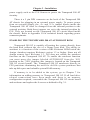
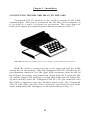
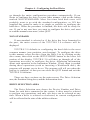
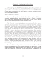
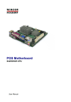
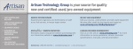
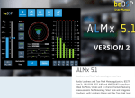
TRUMPCARD 500 AT
User’s Manual
INTERACTIVE VIDEO SYSTEMS
TRUMPCARD 500 AT
User’s Manual
Hardware Design
Erick Moody
TCUTILS User Interface
Sam Noonan and K. Fisk
SCSI Drivers
Sam Noonan
COPYRIGHT 1991 INTERACTIVE VIDEO SYSTEMS
ALL RIGHTS RESERVED
‘How Swede It Is’
Amiga is a trademark of Commodore Business Machines, Inc.
Workbench is a trademark of Commodore Business Machines, Inc.
INTERACTIVE VIDEO SYSTEMS
Phone: (714) 890-7040 • Fax: (714) 898-0858
CHAPTER 1 - INTRODUCTION .................................................
TRUMPCARD 500 AT PACKAGE CONTENTS .................
MANUAL ORGANIZATION ...............................................
CHAPTER 2 - HARD DRIVE FUNDAMENTALS .....................
CHAPTER 3 - TRUMPCARD 500 AT INSTALLATION ............
DRIVE MOUNTING. ...........................................................
DRIVE CONNECTION ........................................................
POWER SOURCE SELECTION ..........................................
ENABLING THE AUTOBOOT ROM ..................................
CONNECTING TRUMPCARD 500 AT TO THE A500 .......
CHAPTER 4 -CONFIGURING THE HARD DRIVE .................
CONFIGURING THE HARD DRIVE .................................
FIRST TIME, FRESH DRIVE .............................................
STANDARD .........................................................................
NON-STANDARD ...............................................................
DRIVE SELECTION AREA ................................................
THE PARTITION SIZER .....................................................
THE INFORMATION AREA ...............................................
CHAPTER 5 - ADVANCED USER’S AREA ................................
DETAILED PARTITION INFORMATION WINDOW .........
DEVICE ...............................................................................
VOLUME NAME ................................................................
SIZE .....................................................................................
DOS TYPE ...........................................................................
BUFFERS .............................................................................
MOUNT ...............................................................................
MASK ..................................................................................
MAXIMUM TRANSFER ....................................................
BOOT PRIORITY ................................................................
BOOTABLE .........................................................................
LOW AND HIGH CYLINDER ............................................
WINDOW GADGETS ....................................................................
THE MENU BAR ...........................................................................
THE PROJECT MENU .................................................................
ABOUT.................................................................................
THE SETUP OPERATIONS MENU ............................................
1
1
2
3
8
8
9
9
10
11
13
13
13
13
14
14
15
16
17
17
17
18
18
18
18
19
19
19
19
19
20
20
21
21
21
21
THE COMMAND MENU .............................................................
LOW LEVEL FORMAT ........................................................
CERTIFY DRIVE .................................................................
ADD TO THE MOUNTLIST ................................................
PERFORM AMIGA DOS FORMAT .....................................
WRITE PARTITION INFORMATION .................................
COPY WORKBENCH ..........................................................
CREATE BOOT DISK ..........................................................
CLEAR DRIVE ....................................................................
SELF TEST ..........................................................................
PARK DRIVE HEADS .........................................................
THE OPTIONS MENU ..................................................................
CERTIFY .............................................................................
DRIVER ...............................................................................
FORMAT ..............................................................................
CLEAR DEFECT LIST .........................................................
CACHING ............................................................................
CHAPTER 6 -USING THE HARD DRIVE ..................................
AUTOBOOTING WITH TRUMPCARD 500 AT .................
BOOTING FROM A FLOPPY ..............................................
GAME SWITCH ..................................................................
DETAILS OF THE BOOT PROCESS ..................................
USING THE Trumpcard 500 AT HARD DISK SYSTEM ......
REMOVABLE MEDIA SUPPORT........................................
CHAPTER 7 - ADDING MEMORY..............................................
SIZING OPTIONS ..........................................................................
ADDING AND REMOVING SIMM MODULES .................
MEMORY CONFIGURATION.............................................
DIAGNOSTICS ..............................................................................
APPENDIX A - PARTITIONING EXAMPLE .............................
APPENDIX B - USING SUBDIRECTORIES ...............................
APPENDIX C - TECHNICAL SPECIFICATIONS .....................
APPENDIX D - TECHNICAL SUPPORT ....................................
21
22
22
22
23
23
23
23
24
24
24
25
25
25
25
26
26
29
29
29
29
30
31
32
33
33
33
34
36
38
40
42
44
Chapter 1 - Introduction
CHAPTER ONE
INTRODUCTION
TRUMPCARD 500 AT PACKAGE CONTENTS
Thank you for purchasing the Trumpcard 500 AT expansion system
for the Amiga 500. Check the contents of your Trumpcard 500 AT
package for the following items:
Trumpcard 500 AT Hard Disk Expansion System
1
1
1
8
4
4
Trumpcard 500 AT expansion chassis
3 in. 40 pin AT/IDE interface cable
Trumpcard 500 AT disk configuration/memory test disk
philips pan head self tapping screws
6-32 x 1/4" philips pan head bolts
nylon shoulder washers
If any of these items are missing contact your Trumpcard 500 AT
dealer or IVS immediately to replace the missing items.
1
Chapter 1 - Introduction
MANUAL ORGANIZATION
Since the Trumpcard 500 AT card provides the combined
functions of an AT/IDE Hard Disk controller and a memory expansion
board, this manual contains sections covering each of the functions of
the card. The first part of the manual provides information for first
time hard disk users as well as seasoned veterans. Chapter 2 provides
first time hard drive users with a broad overview of hard disk concepts.
This chapter may be skipped by those who are familiar with hard drives
or by those who aren’t, and just can’t wait to get the thing running.
Chapter 3 provides installation guidelines for the Trumpcard 500 AT.
Chapter 4 provides information about setting up your hard disk drive
using the TCUTILS 2.0 software. Chapter 5, The Advanced User’s
Section, covers the workings of the TCUTILS 2.0 software in great
detail. It is NOT necessary to read this chapter in order to set up your
hard disk. Chapter 6 covers using the hard disk controller portion of
your Trumpcard 500 AT. Chapter 7 covers adding memory to the
Trumpcard 500 AT and the usage of the memory test software.
There are also several appendicies in the back of the manual.
Appendix A illustrates a step by step example of setting up a drive with
3 partitions mixing the FastFilingSystem and the Old filing system on
the same drive. The example is easily extended to any number of
partitions. Appendix B provides information on using subdirectories
instead of partitions on your hard disk. Appendix C provides technical
specifications for the Trumpcard 500 AT series. Appendix D provides
information about contacting IVS Technical Support.
Hard disk drives are not the easiest devices to get up and running.
For this reason, IVS has devised TCUTILS 2.0, an automated hard
drive configuration utility package that makes the hard drive
installation process as simple and worry free as it can be. Follow the
steps outlined in this manual and you should be using your new hard
drive in about 30 minutes. Naturally, if you have any difficulty or
questions, contact your dealer or IVS Technical Support.
Thanks again for buying a Trumpcard 500 AT!
2
Chapter 2 - Fundamentals
CHAPTER TWO
HARD DRIVE FUNDAMENTALS
Hard drives offer two big advantages over floppy disks; speed
and capacity. A program that takes 20 seconds to load from a floppy
disk will load in under 2 seconds from a hard drive. Whereas a 3.5"
Amiga floppy disk can store 880 Kbytes of data, a hard disk can store
from 20 Mbytes to over 500 Mbytes. Therefore hard drives are about
10 times as fast as floppy drives and they can store between 20 and 500
times the data as a floppy disk. Hard drives operate in the same manner
as floppy disks in that a magnetically sensitive disk rotates on a spindle
and as it spins, magnetic fluctuations in its surface(s) pass under a
magnetic head sensing these fluctuations as bits of data. Here is where
the similarity ends. While a floppy disk has two surfaces (top and
bottom), a hard drive may have several disk platters stacked on top of
each other to increase its capacity. For example, if there is one platter,
the drive has two surfaces, top and bottom. If the drive has two platters,
there are four surfaces, top and bottom on each platter. Similarly, if the
drive has three platters, it has six surfaces, top and bottom on each of
the three platters. There is a read/write head for each surface; therefore,
a three platter drive has six read/write heads. Each surface is divided
into tracks (Fig. 2-1).
In seeking data the read/write heads move in and out from one
track to another. As the data stored on a track passes under the
read/write heads it is sensed by the head, processed, and transferred
into the computer through the Trumpcard 500 AT interface. The
number of tracks on a particular drive is set by the drive manufacturer.
Each track on a disk drive is further broken down into data blocks
referred to as sectors (Fig. 2-2). Sectors can be any size but are usually
set at 256 bytes or 512 bytes. Currently, AmigaDOS only supports 512
byte sectors. The number of sectors or blocks per track is also set by the
drive manufacturer.
3
Chapter 2 - Fundamentals
TRACK 0
TRACK 1
TRACK 2
TRACK n
DISK PLATTER
TOP VIEW
FIGURE 2-1. Hard disk platters are divided into
concentric rings called TRACKS
Hard drives that have multiple platters, or disk surfaces are also
characterized by a number of cylinders. Each platter has a top and a
bottom surface on which data may be stored. As described above, these
surfaces are divided into concentric circles called tracks and there are a
set number of tracks per surface as defined by the drive manufacturer.
Tracks may be thought of as positions to which the read/write heads
move. For a particular position, the heads may access several tracks,
depending on the number of platters. For example, if the disk drive has
3 platters, there are 6 surfaces hence, 6 tracks that may be accessed at
any read/write head position. In such a case, the combination of tracks
at any given head position is referred to as a cylinder. It follows that
there are as many cylinders on a disk drive as there are track positions
on a surface. The name cylinder is derived from the shape of several
circles (tracks) stacked on top of each other.
4
Chapter 2 - Fundamentals
28
26
27
25
1
23
24
TRACK n
2
22
512 byte
s per se
3
ctor
4
21
20
5
19
6
DISK PLATTER
TOP VIEW
18
7
17
8
16
9
15
11
10
12
13
14
FIGURE 2-2. Hard disk tracks are divided into adjacent
sections called BLOCKS or SECTORS
New hard disk drives have no data on them and so must be
prepared for use. Preparation of the drive entails three primary steps;
Low Level Format, Certification, and High Level Format.
Low level format is a process that organizes the sectors on the
disk drives tracks. Figure 2-2 illustrates a track made up of 28 sectors.
In some cases it may be desirable to reorganize the sequence of sectors
on a track. The sequence of sectors on a track is referred to as the
interleave. Interleave is a means of sequencing sectors to maximize the
throughput of data to and from the drive, and is based on factors like
the computer’s CPU speed, the computer operating system, and the
controller card used by the system. Interleave is defined as a ratio.
Figure 2-2 illustrates a track with a 1:1 interleave, i.e., sectors are
organized in a sequential fashion around the track. Figure 2-3 illustrates
a track with a 2:1 interleave. Notice how numerically sequential sectors
are placed two physical sector positions apart. Varying the interleave of
a drive allows time to pass between retrieval of data from numerically
sequential sectors. For example, if a drive had a fixed 1:1 interleave
and was not able to get data from a sector because the system was still
processing data from the previous sector, the drive would have to wait
for one disk revolution for the next sector to come around again.
5
Chapter 2 - Fundamentals
14
15
28
13
1
12
27
TRACK n
16
26
512 byte
s per se
2
ctor
17
11
25
3
10
18
DISK PLATTER
TOP VIEW
24
4
9
19
23
5
8
20
21
6
7
22
FIGURE 2-3. Hard disk track with 2:1 interleave
In such a case, throughput may be increased by changing the interleave
from 1:1 to 2:1. Referring to Fig. 2-3, while data from sector 1 is being
processed, sector 16 is passing under the read/write heads. By the time
sector 2 gets to the heads, the drive should be finished processing sector
1 and ready to get data from sector 2. If this is not the case, the
interleave should be increased to 3:1 or 4:1. Interleave is a very
important parameter and will greatly affect the performance of your
computer when it accesses the hard drive. The TCUTILS 2.0 utilities
package has default values for interleave depending on the drive and
file system you are using. In general, these values should not be
changed as IVS has determined the optimum setting for each drive/file
system combination. Interleave applies to the entire drive and cannot be
changed on a partition to partition or track to track basis. If a drive is
using both the FastFileSystem and the old file system, the interleave
should be optimized for FFS.
Certification is a process whereby the disk drive is examined for
bad spots on the disk. Bad areas of the disk are referred to as bad
sectors even though the bad area may not destroy an entire sector. Bad
sectors are not all that unusual on hard drives and so the drive
manufacturers include a small number of tracks specifically for the
purpose of bad sector remapping. The process of identifying and
remapping bad sectors is called certification. TCUTILS 2.0 includes a
very comprehensive set of certification tests. The tests are broken down
6
Chapter 2 - Fundamentals
into two broad categories, Destructive and Non-Destructive.
Destructive certification actually writes over any data on the drive and
so should be used only on new disk drives or on drives where loss of
data is not important. Non-Destructive tests will not overwrite data on
the drive and so may be used at any time without suffering loss of data.
It is important to note that hard drives are susceptible to soft errors,
intermittent errors that do not represent bad sectors but rather, an error
condition that will not repeat. If a hard drive appears to have a bad
sector, run a certification test, write down the bad sector number and
repeat the test. If the same number appears, the drive has a hard error
and the sector should be remapped. If not, the error was a soft error and
the sector should not be remapped.
High level formatting of a drive prepares a drive for use with a
particular Disk Operating System, or DOS (AmigaDOS in this case).
Hard disk drives are extremely sensitive to shock and vibration.
The disk platters spin at a rate of 3600 RPM and the aerodynamically
shaped heads literally fly over the surfaces of the disks at a distance so
small that a single smoke particle will lodge between the disk and
heads and can scratch the disk surface and render it useless. There are
intricate air filtration systems and shock mounting systems built into
every hard drive but a little extra care and caution goes a long way in
maintaining a reliable mass storage system for your computer.
7
Chapter 3 - Installation
CHAPTER THREE
TRUMPCARD 500 AT INSTALLATION
TRUMPCARD 500 AT DRIVE MOUNTING
If your Trumpcard 500 AT already has a drive mounted in it go
directly to the section titled Connecting Trumpcard 500 AT To The
A500. If the Trumpcard 500 AT enclosure does not contain a hard drive
you must mount a 3,5" half height drive in the enclosure. To do so,
remove the eight screws on the bottom of the enclosure as shown in
figure 3-1.
Remove 8
Screws to Open
Chassis
FIGURE 3-1: Take out 8 screws to remove Trumpcard 500 AT chassis cover
Carefully separate the top section of the Trumpcard 500 AT
chassis from the bottom by prying the two halves apart at the center of
the enclosure and then pulling the top section off. If connected, pull the
power and disk activity LED leads from the Trumpcard 500 AT circuit
board and remove the board from the Trumpcard 500 AT chassis base.
The Trumpcard 500 AT circuit board has 4 holes in it for
mounting the hard drive. The holes are spaced to accept all 3.5" SCSI
hard disk drives. Locate the corresponding holes on the hard drive.
Align the holes in the chassis with those of the drive and attach the
8
Chapter 3 - Installation
drive to the chassis with the four 6-32 x 1/4" screws included with the
Trumpcard 500 AT. Do not overtighten.
NOTE:
Mounting the hard drive directly to the Trumpcard 500 AT circuit
board will void the warranty. The hard drive must be held away
from the circuit board with the nylon spacers or shoulder
washers that are included with the Trumpcard 500 AT.
TRUMPCARD 500 AT DRIVE CONNECTION
With the drive mounted on the Trumpcard 500 AT circuit board,
connect the drive to the circuit board using the 40 pin ribbon cable. All
connectors are polarized so that they cannot be installed improperly.
Connect one end of the cable to the drive itself and the other end of the
cable to the 40 pin header labelled CN1301 on the Trumpcard 500 AT
circuit board.
Insert the 3 wire power cable labelled CN1302 on the Trumpcard
500 AT circuit board into the mating power connector on the drive.
This connector is also polarized so that it cannot be installed
improperly.
Reconnect the disk and power LEDs to the Trumpcard 500 AT
circuit board. The black wire of both LED’s connect to the center post
of their respective 3 pin headers. Each header is clearly labelled
‘POWER LED’ and ‘DISK LED’.
TRUMPCARD 500 AT POWER SOURCE SELECTION
There are two ways to power the Trumpcard 500 AT, internal or
external power. The internal power supply will work fine to run one
hard drive and the Trumpcard 500 AT. If you feel uncomfortable using
the Amiga supply or if the system has an accelerator or other board that
may use excessive amounts of current you should use an external
9
Chapter 3 - Installation
power supply such as the IVS Sourcer to power the Trumpcard 500 AT
circuitry.
There is a 5 pin DIN connector on the back of the Trumpcard 500
AT chassis for plugging in an external power supply. To source power
from an external supply, the +5v and +12v jumper blocks inside the
Trumpcard 500 AT must be changed from the internal position to the
external position. Both these jumpers are set to the internal position by
IVS. They are located on the Trumpcard 500 AT circuit board inside
the chassis. Refer to Appendix G for technical details regarding power
connector pinouts.
ENABLING THE TRUMPCARD 500 AT AUTOBOOT ROM
Trumpcard 500 AT is capable of booting the system directly from
the hard disk without the use of a floppy boot disk. The ability to
autoboot is a function of the version of the Kickstart ROM inside the
Amiga. Autoboot requires Kickstart version 1.3 or higher. Since not all
Amiga owners have Kickstart 1.3, IVS does not enable the autoboot
function on the Trumpcard 500 AT. To enable the autoboot function
you must move the jumper labeled AUTOBOOT from the ‘NO’
position to the ‘YES’ position (this jumper is located on the Trumpcard
500 AT circuit board). The Trumpcard 500 AT autoboots directly to
FFS partitions eliminating the need for old file system partitions that
take up disk space and valuable system RAM memory.
If memory is to be added to the system, go to Chapter 7 for
information on adding memory to Trumpcard 500 AT. If all hard drive
related connections have been made and there is no memory
configuration required, reassemble the Trumpcard 500 AT circuit board
and enclosure and replace the 8 screws as defined in Fig. 3-1.
10
Chapter 3 - Installation
CONNECTING TRUMPCARD 500 AT TO THE A500
Trumpcard 500 AT attaches to the A500 by means of the A500
expansion port. This port is located on the left side of the computer. It
is covered by a piece of plastic for protection. The cover must be
removed to expose the expansion port connector as shown in Fig. 3-2.
FIGURE 3-2: Remove Expansion Port Cover to Expose A500 Expansion Bus Connector
With the A500’s expansion port cover removed and the A500
resting flat on the desktop, align the Trumpcard 500 AT such that its 86
pin expansion connector is to the right. Both enclosures must be flat on
the desktop for proper interconnection. Align both the Trumpcard 500
AT and the Amiga 500 enclosures so that their front and rear edges line
up and carefully push the Trumpcard 500 AT’s 86 pin connector into
the A500’s expansion port slot. Without much force, the Trumpcard
500 AT will slide onto the A500 connector such that the two units
nearly touch each other and appear as one unit as shown in Fig. 3-3.
11
Chapter 3 - Installation
FIGURE 3-3: TRUMPCARD 500 AT AND A500 PROPERLY MATED FORM ONE UNIT
With Trumpcard 500 AT properly attached to the A500 and all
connections and hardware jumper selections made on the circuit board,
the system is ready to be powered up.
12
Chapter 4 - Configuring the Hard Drive
CHAPTER FOUR
CONFIGURING THE HARD DRIVE
Once the Trumpcard 500 AT has been attached to the computer,
you must configure the hard disk. This process involves formatting the
hard disk, checking it for bad sectors, and installing the Workbench
software to allow auto-booting from the hard disk. These processes are
performed using the TCUTILS 2.0 program found on the Trumpcard
500 AT Hard Disk Formatting Utilities diskette.
To configure the hard disk, boot the Amiga with a Workbench
disk, and then make a COPY of the Trumpcard 500 AT Boot disk. The
Trumpcard 500 AT disk is self modifying, and the original disk should
never be used except to create backup copies. Again, before you
proceed, make a copy of the Trumpcard 500 AT Hard Disk Formatting
Utilities diskette. If you’re not sure how to copy disks, consult the
documentation that came with the Amiga.
After making the backup, reboot the system, using the new
Trumpcard 500 AT BACKUP diskette instead of the normal
Workbench disk.
FIRST TIME, FRESH DRIVE
If the drive has never been formatted before TCUTILS 2.0 will
display the easy setup screen. This screen consists of 3 buttons labelled
‘STANDARD’, ‘NON-STANDARD’, and ‘QUIT’. The screen also
shows the type of drive connected to the system and its size in
Megabytes.
STANDARD
To configure the hard drive with a single partition and formatted
normally, click on the button marked STANDARD. TCUTILS 2.0 will
13
Chapter 4 - Configuring the Hard Drive
go through the entire configuration procedure automatically. If you
desire to configure the drive in some other manner, click on the button
marked NON-STANDARD. Most first time hard disk users will
probably want to go with the standard configuration, so IVS has
supplied this option to make it as simple as possible to configure the
hard drive. When the procedure is finished, the drive will be ready for
use. If you’re not sure how you want to configure the drive, and want
to read the manual some more, select QUIT.
NON-STANDARD
If non-standard is selected or if the drive has been formatted in
the past, the main screen of the TCUTILS 2.0 software will be
displayed.
TCUTILS 2.0 defaults to configuring the hard disk in the most
common manner (one partition, auto-booting). To configure the drive
in this manner, select the drive from the Drive List by clicking on the
drive name, then click on the SETUP DRIVE button in the lower left
portion of the display. TCUTILS 2.0 will then go through all of the
operations necessary to configure the drive, displaying information
about each operation in the Instruction Window. If user input is needed
during these operations (such as inserting a Workbench disk), the
program will prompt you to do so. The program will tell you when the
process is complete, so that you can select the QUIT button and exit the
TCUTILS 2.0 software.
There are three sections on the main screen: The Drive Selection
area, the Partition Sizing Area, and the Information Area.
DRIVE SELECTION AREA
The Drive Selection area shows the Device Number and Drive
Name for each drive connected to the system. A drive must be selected
to perform any operations, and only one drive can be selected at any
time. When a drive is selected or reselected, its current configuration
will be reflected in the state of the utilities software.
14
Chapter 4 - Configuring the Hard Drive
After entering the TCUTILS 2.0 software, if no drive is shown on
the list, check all connections. If TCUTILS 2.0 cannot determine the
type of drive connected, it will assign the drive the name UNKNOWN.
If you have an embedded AT drive and it is shown as UNKNOWN,
call IVS Technical Support.
THE PARTITION SIZER
Some people prefer to divide their drive up into different
sections, called partitions. Each partition acts as if it were a separate
drive, with each partition having its own name. If you want to divide
the drive into various partitions, use the Partition Sizer.
The Sizer is a vertical column, representing the free space
available on the hard disk. TCUTILS 2.0 defaults to a single partition
the size of the entire drive. If you wish to divide the drive into multiple
partitions, remove the single partition by double clicking in that
partition. A new window, the Detailed Partition Information Window,
will appear, overlaying the Drive Selection Area. Click on the
REMOVE button to remove the selected partition. The detailed
partition window will disappear. To create a partition, click and hold in
the free space area of the partition sizer. To determine the size of the
partition, drag the mouse in the partition area and move the mouse
downward to increase the size, or upward to decrease the size. A
horizontal line will follow the mouse movement, showing the size of
the partition. Create as many partitions as you like by repeating this
click and drag operation in the remaining free space. Partition sizes are
shown graphically; the size of a partition as shown in the sizer is
rounded to the 1st significant digit. For more exact sizes, see the
section on the Detailed Partition Information Area in the Advanced
User’s Chapter.
Be warned that each partition consumes between 25 and 60k of
RAM, depending on the file system used and the buffer size. Using
subdirectories rather than partitions saves memory and allows for the
same operations as partitions, except AmigaDOS reformatting of
15
Chapter 5 - Advanced User’s Area
VOLUME NAME
Volume names default to being blank. You must define the
Volume name for each partition. Keep the names short (WORD for
Word Processing files and data, for example), and make sure there are
no spaces in the name. There is a one to one corellation between the
volume name and the partition. Unlike Device Names, Volume names
will not be changed by the system. It is imperative that you refer to the
Volume names, not the Device names, when working with hard disks
and partitions.
SIZE
The Size parameter shows the current size of the partition in
Kilobytes. To change the size, type in a new value. Note that the size
is rounded to the cylinder boundaries of the partition. This parameter is
used to set partition sizes that are too difficult to set graphically in the
Partition Sizer. When the size field is altered the high cylinder value for
the partition will be altered automatically after the ‘ACCEPT’ button is
pressed.
DOS TYPE
The DOS type allows a partition to be formatted using the Fast
File System (FFS), the Old File System (OFS), or Max. FFS is the
default, and should always be used over OFS, unless there is a specific
reason to use OFS. The Max option can be used to set aside a partition
to use with a Mac emulator. Max partitions will need to be formatted
from within the Mac emulator. To select which DOS to use, click the
DOS button until the desired DOS is shown.
BUFFERS
The Buffers option allocates FFS buffers. Each increment in the
Buffer field represents 512 bytes of system memory. The default
buffer size is 20, which is determined to be optimum. The value can be
changed but numbers higher than 20 will have no noticeable effect.
18
Chapter 5 - Advanced User’s Area
MOUNT
Mount selects whether the partition mounts automatically. It is
used to turn the partition on and off. Note that if Mount is set to OFF,
it cannot be mounted by using the Mount command from the CLI.
MASK
The Mask option is a bitwise address mask that establishes areas
of memory that can or cannot be used for disk data transfers. This
information has been set for optimum performance, and should not be
changed.
MAXIMUM TRANSFER
The Maximum Transfer represents the maximum number of
bytes that can be transferred in a single operation. This information
should not be changed, as it has already been set at the maximum value
and lowering it can cause lower drive performance.
BOOT PRIORITY
The Boot Priority sets the priority of partitions at boot time.
Using this parameter establishes which partition will boot if there are
multiple bootable partitions, and is mainly used when the system is
using more than one hard disk controller. The acceptable range for this
parameter is -127 to +127 (the higher the number, the higher the
priority). Do not set the number higher than 4, as 5 is the priority
number for floppy drives.
BOOTABLE
The bootable option controls whether a partition is bootable, and
in conjunction with boot priority determines the order in which order
partitions will Boot.
19
Chapter 5 - Advanced User’s Area
LOW AND HIGH CYLINDER
The Low and High Cylinder parameters are set automatically by
the partition sizer. Low and high cylinders control the upper and lower
boundaries of a partition. Partitions cannot overlap, so the low cylinder
of a partition must start at least one cylinder above the high cylinder of
the previous partition. These parameters are presented here for
reference and although they can be changed by typing in a new value,
it’s recommended that partition size be altered from the graphic display
of the partition window. These values may be altered to provide a finer
control over partition size than is available using the partition sizer.
Never use cylinders 0 and 1, as these are reserved by IVS for Rigid
Disk Blocks and Autobooting.
WINDOW GADGETS
There are 3 gadgets at the bottom of the Detailed Partition
Information Window; ‘REMOVE’, ‘ACCEPT’, and ‘CANCEL’.
REMOVE removes the partition from the drive and returns to the main
screen. Use ‘REMOVE’ to re-partition a drive or to easily change the
size of a partition. CANCEL exits to the main screen ignoring any
parameter changes made in the window. ACCEPT makes all parameter
changes take effect and exits to the main screen.
Once the partitions are set up the drive is ready to be configured.
To configure the drive, click on the SETUP DRIVE box in the main
screen. The system tells which operation is being performed, and an
estimation of how long each operation will take where applicable.
When all operations are complete, the hard disk is ready for use. Press
QUIT to exit TCUTILS 2.0.
20
Chapter 5 - Advanced User’s Area
THE MENU BAR
To alter a sequence of events, or perform individual utility
commands, use commands and options along the menu bar. There are
four menus along the menu bar at the top of the screen: Project, Setup,
Commands, and Options. In the section below, each menu and each
item on the menu will be explained.
THE PROJECT MENU
ABOUT
Selecting this command shows the current TCUTILS 2.0
software revision, as well as the current ROM version of the
Trumpcard 500 AT.
THE SETUP OPERATIONS MENU
The Setup Operations Menu contains the operations that are
performed when the ‘SETUP DRIVE’ button is pressed. The
TCUTILS 2.0 software is capable of deciding which operations need to
be performed on a drive, and then only running those operations. For
example, if the drive has previously been formatted and you decide to
change the partition information, TCUTILS 2.0 will only perform the
necessary operations to change that information. If uncertain as to
whether or not a particular operation will be performed, check this
menu. If a menu item has a checkmark next to it, that operation will be
performed. For a definition of each command see the section on the
Command Menu.
THE COMMAND MENU
The Command Menu contains all of the options available on the
Setup Operations menu, plus some commands only found on this menu.
The difference between this menu and the Setup Operations Menu is
21
Chapter 5 - Advanced User’s Area
that any item selected from the Command Menu will be performed immediately, while commands selected on the Setup Operations Menu
will only be performed when the Setup Drive button is clicked. The
menu items that are common between the two menus perform their
functions in the same way and are detailed below.
LOW LEVEL FORMAT
Formatting causes the disk to be broken up into small storage
units called blocks. Since most drives are shipped from the factory
unformatted, they must be formatted which takes from a few seconds to
10 minutes to complete. Extremely large drives can take a half hour or
more to format (the larger the drive, the longer the format time). Note
that a Low Level format only sets up the blocks, and is not the same as
the Format command found in Amiga DOS.
CERTIFY DRIVE
Certify scans through the drive looking for soft or hard errors.
Hard errors are automatically reassigned, although this may be changed
under Certify on the Options Menu. Soft errors can be caused by bad
cables, bad power supplies etc, and will not be reassigned because they
are not actually hard errors. The easiest way to tell the difference
between hard and soft errors is that hard errors are always repeatable,
while soft errors are not Options associated with the Certify Drive
command are found under Certify on the Options menu, and are
covered in that section.
ADD TO THE MOUNTLIST
Selecting this item will have TCUTILS 2.0 write the partition
information in a mountlist style and save this information in the current
DEVS directory. While the Trumpcard 500 AT does not need this
information, the option is provided in case another piece of hardware or
software being used does need it. This command defaults to OFF, and
must be selected if this information is to be created during drive
configuration.
22
Chapter 5 - Advanced User’s Area
PERFORM AMIGA DOS FORMAT
An Amiga DOS format allows the hard drive to be used with the
Amiga computer. TCUTILS 2.0 performs its own Amiga DOS format,
which is faster but identical to a standard system DOS format.
WRITE PARTITION INFORMATION
This operation writes the RDB (Rigid Disk Blocks) data to the
hard disk drive. This is the information that was created in the partition
window.
COPY WORKBENCH
This command is used when the hard drive is to be used as the
boot device. TCUTILS 2.0 will prompt you to insert a Workbench disk
into the DF0: floppy drive. It is important to use an unaltered copy of
Workbench because Trumpcard 500 AT requires certain Workbench
files for proper operation. Use the original Workbench disk and then
make any desired changes to the Workbench after it has been copied to
the hard disk.
CREATE BOOT DISK
This command alters the Trumpcard 500 AT Hard Disk
Formatting Utilities diskette to allow access to the hard disk on systems
that do not support autobooting. Remember to use a COPY of the disk
utilities diskette, not the original. If necessary, the boot diskette can be
returned to its original state by clicking on the Make Original Boot icon
on the boot diskette.
23
Chapter 5 - Advanced User’s Area
The following commands are not available on the Setup
Operations Menu.
CLEAR DRIVE
If you’ve previously configured the hard drive with partition
information, and later decide to change the configuration of the drive,
use this command. It will remove all partition info and return the
TCUTILS 2.0 software to its default state. Note that this command
only removes the partition info within the TCUTILS 2.0 software. To
actually change the information on the drive, press the Setup Drive
button. To undo Clear Drive, reselect the drive from the drive list on
the main screen. Remember to back up any important files that were
on the drive before selecting Clear Drive, as the files will be lost in the
process.
SELF TEST
This command will run an internal diagnostic test on the hard
disk. After selecting this command, the test will be run, and a PASS or
FAIL message will be displayed. If the self test fails, consult the hard
disk documentation or contact the hard disk’s manufacturer to correct
the problem.
PARK DRIVE HEADS
This command parks the heads of the selected drive. Once the
heads are parked the system power must be cycled for the drive to
become active again. Most newer drives automatically park their heads
at power down.
24
Chapter 5 - Advanced User’s Area
THE OPTIONS MENU
The items found on this menu interact with items found on the
Command menu, or control how the hard disk works with the
computer.
CERTIFY
The four options here interact with the Certify Drive command.
The Non Destructive test scans the entire drive and reassigns all hard
errors. The Destructive Write test tests the drive cabling and controller
for possible read/write errors. It does not check the entire drive.
The next two items control what happens to any bad blocks found
during certification. Reassign blocks tells the computer to reassign the
bad block itself. Reformat Defects reformats the hard disk removing
the bad blocks. You can choose neither option, or one or the other. If
neither is selected, the software will not reassign any bad blocks it
finds. Note that using these two items can wipe out data on the drive.
A warning will be issued after selecting the Certify Drives command or
when pressing the Setup Drive button, allowing you to abort these
operations.
DRIVER
This option is not used on the AT disk controller.
FORMAT
These two options interact with the Low Level Format command.
The first, Interleave, defaults to a value determined by whether or not
FFS was chosen while setting up Partitions. In general, the Interleave
will be low (1-3) for FFS and high (5-15) for OFS. The Interleave rate
is drive dependent and greatly affects drive performance. It should not
be changed from the default value unless there is a specific reason, as
the default values are optimized for the best possible performance.
25
Chapter 5 - Advanced User’s Area
CLEAR DEFECT LIST
This option will clear all user defined defects on the drive.
CACHING
The last two choices on the Options menu are Read Cache and
Write Cache. Putting a check next to either of these will turn that
particular cache on.
Using a cache can help speed up accesses to a hard drive that
does not already have a cache built in (Quantum drives have built in
caches, for instance). A cache is a special area of memory where the
Trumpcard 500 AT stores the most recently used information read in
from the hard drive. When you request data from the disk at a later
time, the Trumpcard 500 AT checks the cache first to see if the data is
already there from the last time; if it is not, the hard drive must be
accessed.
If the data is in the cache, it can be transferred straight to the user
without accessing the disk at all. This can result in a significant gain in
throughput, especially if the same data needs to be accessed frequently.
Another feature of the cache helps speed up accesses through
AmigaDos. The Trumpcard 500 AT will never read a single block
from the drive; it always reads groups of at least 16. AmigaDos, on
the other hand, frequently makes single-block reads, even on groups of
consecutive blocks. By reading in more data than required, the caching
algorithm anticipates AmigaDos’s requests in most cases, and has the
data in memory when AmigaDos asks for it later. This cuts down on
overhead.
The Read Cache defaults to ON and a size of 321 bytes, which
has been determined to be optimum for most AmigaDos usage.
However, experimentation with various sizes may produce better
results. The cache eats up system memory so balance the need for
26
Chapter 5 - Advanced User’s Area
memory with the need for speed. This also applies to the Write Cache,
which occupies a separate area of memory.
A similar scheme is used with the Write Cache. When
AmigaDos writes a file, it may write many individual blocks to the
drive, even though they are consecutive. With a write cache turned on
Trumpcard 500 AT accesses the disk much more efficiently. Instead of
writing directly to the disk every time AmigaDos asks it to, Trumpcard
500 AT puts the data in a write cache. The cache is written to the disk
all at once when needed. This results in a great increase in throughput,
because writing large blocks of data to the drive reduces overhead, but
unlike the read cache, it has a severe drawback.
The problem with write caching is that if, for some reason, you
shut off the power, reset the Amiga, or have a “Guru”, whatever is in
the cache might not have been written to the disk. This could result in
a loss of data and could possibly result in complete failure of the
partition! The option of using the write cache is there if you want the
speed.
To reiterate: DO NOT USE WRITE CACHING unless you are
absolutely sure you can afford to lose all data on the partition you are
using! This is only a sensible precaution. In general, the time you
might gain by using a write cache cannot make up for the security you
will lose: it is like being on a high wire with no net. Read caching, on
the other hand, is completely safe and cannot result in any loss of data
from the hard drive.
A note on performance: caching helps to maintain a constant
throughput close to the theoretical maximum of the drive. If you read
or write large numbers of blocks at once (picture files, for instance), the
improvement over non-caching will not be as great as if you were
reading and writing groups of small files. Caching helps improve
normal, everyday use of the hard drive (getting directories, using a
database, etc.).
Both Read and Write Caching can be turned on and off at will
from TCUTILS 2.0, so if you are not sure what to use, just ignore it.
27
Chapter 5 - Advanced User’s Area
You can always change it later (it defaults to the safest configuration,
read cache on, write cache off).
28
USING THE TRUMPCARD 500 AT HARD DRIVE
CHAPTER SIX
USING THE TRUMPCARD 500 AT HARD DRIVE
AUTOBOOTING WITH TRUMPCARD 500 AT
Autobooting the system directly from the hard drive requires that
a version 1.3 or higher Kickstart ROM be installed in the Amiga.
Kickstart ROMs are purchased from an authorized Commodore dealer.
Make sure that the BOOT jumper on the Trumpcard 500 AT is set to
work with the correct ROM version in the Amiga: ‘NO’ for Kickstart
1.2, ‘YES’ for Kickstart 1.3 and higher. The Trumpcard 500 AT is
shipped with the jumper in the ‘NO’ position, so to autoboot move the
BOOT jumper shorting block to short the center post to the ‘YES’
position (Kickstartl.2 ROM users cannot autoboot).
When autobooting with an externally powered Trumpcard 500
AT, turn on the external power supply and then turn on the Amiga
power supply. The hard drive will boot, and the Workbench will be
displayed.
BOOTING FROM A FLOPPY
Some users may be concerned about the possibility of viruses. If
the system is booted from a non-Trumpcard 500 AT Boot floppy, the
hard drive will not be mounted, and will not be available for use. This
allows checking of any new programs or something downloaded from a
Bulletin Board System, before installing them on or using them with
the hard disk.
GAME SWITCH
To boot from any floppy and still be able to access the hard disk, hold
down the left mouse button on startup until the floppy drive light comes
on. One note: if the floppy is not bootable, the hard drive will boot.
29
USING THE TRUMPCARD 500 AT HARD DRIVE
DETAILS OF THE BOOT PROCESS
The main difference between autobooting and non-autobooting
systems is the point at which the Trumpcard 500 AT starts its boot
process. Non-autobooting systems (Kickstart 1.2 or before, and other
systems that have the boot jumper set to ‘NOAUTOBOOT’) begin the
initialization process when the binddrivers command is executed;
when the process is complete all partitions will be automounted and
accessible by the system. Autobooting systems start the process at
power up, automount all the partitions and boot from the first bootable
one.
The first thing the Trumpcard 500 AT does is look for a bootable
floppy. If there is one in DF0: the boot process is transferred to the
system. If not, the hard drive autoboot process is continued.
At this time a task is spawned to continue the booting, and the
boot process goes to sleep. If a bootable floppy is not found, the
Trumpcard 500 AT looks at each address on the SCSI bus to see if
there are any bootable hard drives ready. This happens very quickly. If
there are no bootable hard drives ready, the Trumpcard 500 AT will
continually check the SCSI bus until one appears. This goes on for 50
seconds. If no drive appears after 50 seconds, the boot process is
reawakened, control is transferred to the system and the Workbench
requester is displayed.
If a bootable hard drive is found, the boot process is reawakened
and the autoboot process completes. The task continues to check for
new partitions, once every two seconds. It stops looking for new
partitions 60 seconds after the boot process begins (60 seconds from the
time the Amiga was booted or binddrivers was executed). If there are
any partitions mounted from removable media drives, this fast and
efficient task continues to check these drives for cartridge changes
every two seconds.
30
USING THE TRUMPCARD 500 AT HARD DRIVE
USING THE Trumpcard 500 AT HARD DISK SYSTEM
EXTREMELY IMPORTANT !
Complications can arise when multiple hard drives with the same
physical device name are connected to a computer system.
Furthermore, Workbench 2.0 does not support duplicate physical
device names. To ensure unique physical device names, the Trumpcard
500 AT dynamically assigns physical device names to partitions as they
are mounted. For example, your system has a single hard drive with
two partitions whose physical device names are DH0: and DH1:. A
second hard drive with the physical device name DH0: is added to the
system. After the system boots, the first hard drive will be named
DH0: and DH1: as before. The second hard drive will now be assigned
the name DH2: In general, the Trumpcard 500 AT will automatically
rename the duplicate partition by numerically adding the value 1 to the
device’s name until an unused name is found. Therefore, the
Trumpcard 500 AT looks at the existing device name , DH0: and adds
1 to get DH1:. That name is used so 1 is added again to get the name
DH2:. This name is unused and so it it assigned to the second drive.
This dynamic assignment of physical device names can cause problems
for users who refer to their hard drives and partitions by their physical
device name. For this reason, it is imperative that you refer to hard
drives and their partitions by their volume name. Volume names
reference data, not the device on which the data is stored. This is the
name that appears under the partition’s icon in Workbench. Volume
names can be used anytime in place of the physical device names.
Using volume names is particularly important for users of removable
media drives. If you set a drive up using the TCUTILS 2.0
STANDARD configuration, the volume will be named ‘UNTITLED’.
You may change the name using the Workbench Rename feature or the
CLI RELABEL command.
If the hard drive is configured using TCUTILS 2.0, the physical device
name defaults to ‘AUTO’. When the Trumpcard 500 AT mounts a
partition with the physical device name ‘AUTO’, the name will be
changed automatically at boot time to the first available physical device
name, e.g., DH0:. If you change the default name of AUTO to
something else, SYQ:, for example, the Trumpcard 500 AT will try to
use this name when the partition is mounted. If another partition is
already mounted using the name SYQ:, the Trumpcard 500 AT will
31
USING THE TRUMPCARD 500 AT HARD DRIVE
rename the new partition SYQ1: as described above.
Hard drives configured with TCUTILS 2.0 and used on disk
controllers other than a Trumpcard 500 AT will not appear with the
name ‘AUTO’ when booted. Such a drive will appear with
conventional partition names DH0:, DH1:, etc. This is a feature of
TCUTILS 2.0.
REMOVABLE MEDIA SUPPORT
In the event that removable media drives become available with
AT/IDE interfaces, Trumpcard 500 AT supports the use of removable
media. Users of removable media drives may use cartridges partitioned
differently with the Trumpcard 500 AT. Trumpcard 500 AT has
support for these drives built into its autoboot ROM so no diskchange
commands have to be issued to detect cartridge changes. If different
cartridges are configured exactly the same way, removal of one
cartridge and replacement with another will result in the same physical
device name being assigned to both cartridges. If cartridges are
configured differently, a cartridge change results in the old cartridge
name being reserved and the new cartridge is automatically assigned a
new name in the manner described above.
32
Chapter 7 - Adding Memory to Trumpcard 500 AT
CHAPTER SEVEN
ADDING MEMORY TO TRUMPCARD 500 AT
The Trumpcard 500 AT card also acts as a memory expansion
device. The Trumpcard 500 AT can be populated with 2M, 4M, or 8M
of RAM using the latest in memory packaging technology, the SIMM
module. While SIMMs cost a little more money, they offer the densest
packaging options and eliminate the pin incompatibility associated with
256k vs. 1M memory chips. In addition, SIMMs are inherently more
reliable than DIP I.C.’s due to less socket connections and elimination
of the possibility of pins on chips bending during insertion.
SIZING OPTIONS
The Trumpcard 500 AT memory can be configured in 3 different
sizes: 2M, 4M, and 8M. As shown in Figure 7-1, Trumpcard 500 AT
addresses two banks of memory, BANK0 and BANK1. Each bank is
comprised of two SIMM modules; one each for the low byte and the
high byte. Memory must be added a bank at a time. This requirement
dictates that SIMMs must be added to Trumpcard 500 AT two at a
time. To ensure proper operation, BANK0 must always be populated
first before BANK 1. The 2M option requires 2 1Mx8 SIMMs in
BANK 0. The 4M option requires 2 1Mx8 SIMMs in BANK 0 and 2
1Mx8 SIMMs in BANK 1. The 8M option requires 2 4Mx8 SIMMs in
BANK0 and no SIMMs in BANK 1.
ADDING AND REMOVING SIMM MODULES
To add SIMMs to Trumpcard 500 AT, slide the SIMM module
into the socket’s card edge guides. When the SIMM module slides to a
stop at the bottom of the socket press firmly and evenly at the top edge
of the SIMM module to seat the SIMM into the metal socket contacts.
You will hear a click as the SIMM retaining fingers at either end of the
socket snap into the holes at the ends of the SIMM module. Removal is
a more delicate operation. The SIMM retaining fingers must be pressed
out of the holes at the ends of the SIMM while simultaneously prying
the SIMM module up and out of the metal socket contacts. A very
small flat blade screwdriver and patient technician do very nicely for
33
Chapter 7 - Adding Memory to Trumpcard 500 AT
removal of SIMM modules. Pry one end of the SIMM free then pry the
other end free. With both ends free the SIMM module will easily slide
out of the socket. If this operation is performed by a barbarian the
retaining fingers will break and the socket, while not completely
useless, may prove unreliable and noisy. Be Careful!
BANK 0
BANK 1
FIGURE 7-1: Trumpcard 500 AT Memory Bank Numbers and Locations
MEMORY CONFIGURATION
Configuration of the memory consists of 2 selection options:
memory size selection and unlinking memory for diagnostic purposes.
There is a single header block labeled JB1300 in the upper center of the
Trumpcard 500 AT board. JB1300 has 5 pairs of pins. Four pairs are
used to tell the system how much RAM is installed on the Trumpcard
500 AT board. The last pair tells the system whether Trumpcard 500
AT’s memory is to be linked into the system’s free memory pool (see
fig. 7-2). As shipped from the factory, the board is configured for the
amount of RAM installed on the board and the RAM is linked to the
system. Configuration of the board is performed by adding or removing
jumper shorting blocks to JB1300. Note that in the ‘ON’ position, a
shorting block connects a pin in the top row to the corresponding pin in
the bottom row. In the ‘OFF’ position the shorting block is either
34
Chapter 7 - Adding Memory to Trumpcard 500 AT
removed completely or placed on a single pin connecting it to nothing
(this is a safeguard against losing such tiny components). For example,
for a 2M configuration, install a shorting block across the top and
bottom rows at the 2M position on JB1300.
TEST
2M
Ok
8M
4M
JB1300
FIG 7-2: JB1300 Sets TRUMPCARD 500 AT Memory Configuration
8M
4M
2M
Ok
TEST
Improper connection of the shorting block is illustrated in Fig. 73. A shorting block must never short two pins on the same row or the
Trumpcard 500 AT board will not function and the system will
probably not boot.
FIG 7-3: Incorrect Jumper Setting on JB1300
Table 7-1 shows the 3 memory size options and their respective
settings on JB1300. When using the RAM under normal operating
conditions, leave the shorting block in the OFF position for the TEST
pins. If you wish to run the Trumpcard 500 AT diagnostics you must
put a shorting block in the ON position for the TEST pins. Type
AVAIL from a CLI or click on a disk icon from the Workbench to see
that the RAM is there.
35
Chapter 7 - Adding Memory to Trumpcard 500 AT
JUMPER
TEST
Ok
2M
4M
8M
FUNCTION
MEMORY UNLINKED FOR TEST
NO RAM INSTALLED
2M RAM INSTALLED
4M RAM INSTALLED
8M RAM INSTALLED
TABLE 7-1 JB1300 CONFIGURATION OPTIONS
NOTE: JB1300 is read only during boot. If the jumper settings are
changed, the system must be rebooted for the change to take effect.
DIAGNOSTICS
Every Trumpcard 500 AT includes a set of very comprehensive
memory diagnostic tests to verify proper operation of its RAM. IVS
tests each and every Trumpcard 500 AT and its memory before it is
shipped so it is not necessary to test the memory prior to use. In the
event that you suspect that some aspect of the Trumpcard 500 AT’s
memory is not functioning properly, verify operation with the
Trumpcard 500 AT Memory diagnostics. To run an exhaustive set of
tests, unlink the RAM from the system. This is accomplished by setting
the TEST shorting block of Trumpcard 500 AT’s JB 1300 jumper block
to the ON position (refer to TABLE 7-1). With the TEST shorting
block ON reboot the system. Insert the Trumpcard 500 AT Memory
Test Utilities diskette and double click on the MEMTEST icon. Note
that leaving the TEST jumper in the OFF position will cause
MEMTEST to run all tests except the refresh test. The TEST jumper
must be on to test refresh. In the ON position Trumpcard 500 AT’s
memory will not appear to be available for system use. After loading, a
message will appear in the top portion of the screen, telling you the
amount of memory on your Trumpcard 500 AT, and where the memory
location begins. The main section of the memory test screen shows the
number of banks of memory present on your Trumpcard 500 AT card.
Along the bottom of the screen are three buttons: CONTINUE, SKIP
and QUIT. CONTINUE starts the memory test, SKIP allows you to
skip through the different tests to the one you want to perform, and
36
Chapter 7 - Adding Memory to Trumpcard 500 AT
QUIT shuts down the program and returns you to the Workbench
screen.
There are three tests performed when you click on the
CONTINUE button. The first performs Write/Read 1’s to each bank of
memory. The next Write/Reads 0’s to each bank, and the last
alternately Writes/Reads 1’s and 0’s to memory. For the final test
(refresh), you must have the Test Jumper on the Trumpcard 500 AT
card enabled. While the memory diagnostic is running, screen SIMMs
will appear in one of four colors. If a bank appears gray it means that
the Trumpcard 500 AT memory has been configured with that memory
bank disabled. Green SIMMs mean that the SIMM is not actively being
tested. If a SIMM is yellow it is currently under test. If a SIMM is red it
has failed a test. If a SIMM passes a test the word ‘PASSED’ will
appear in the SIMM and the SIMM will turn from yellow (active) to
green (inactive).
37
APPENDIX A - PARTITIONING EXAMPLE
APPENDIX A - PARTITIONING EXAMPLE
In this example, we’re going to configure a Seagate ST157A 48
Megabyte Drive with 3 partitions of roughly 10 meg, 15 meg and 22
meg. The first and last partition will be Fast File System (FFS) and the
second will be Old File System (OFS). IVS DOES NOT
RECOMMEND USING THE OLD FILE SYSTEM (OFS). This
example is for illustrative purposes only.
1)
Boot the system with a COPY of TCUTILS 2.0.
2)
A Simple Setup Screen will appear giving you the option to set
up this drive as a STANDARD drive using only one partition.
Click on NON-STANDARD so that we may set up the drive
in our own fashion.
3)
Since this is the only drive available it is already selected,
otherwise you would select the drive you want to use.
4)
On the right side of the screen you will see the partition sizer
labeled ‘Partition(s)’. It contains one partition which is the
size of the drive. Double Click inside of this partition.
5)
You now have the ‘Detailed Partition Information’ window on
your screen. There is a gadget at the bottom labeled
‘REMOVE’. Press it now. This will remove the partition.
6)
Now move the mouse into the partition sizer, anywhere it
says FREE. Hold down the left mouse button. Keeping the
button down move the mouse up and down. Note that you
have created a new partition and you are changing the size
of it. Move the mouse until the size is approximately 10
megabytes. Release the button.
7)
Repeat the last step by clicking and holding the mouse in the
Free area to create your second partition. Make this one
approximately 15 megabytes.
38
APPENDIX A - PARTITIONING EXAMPLE
8)
All partitions default to using the Fast File System (FFS). For
this partition we want to use the old file system (OFS). To do
this you will need to Double Click inside the second
partition. This will bring up the ‘Detailed Partition
Information’ window. In this window you will
see a button that is titled ‘Dos Type’ and is set to ‘FFS’. Use
the mouse to click on this button. Every time you click on it,
it will change to other types of DOS. Note that there are ‘FFS’,
‘OFS’ and ‘MAX’. ‘MAX’ is for a Macintosh Emulator and
would designate that this partition is to be used with Mac OS.
To use the old file system keep clicking until ‘OFS’ appears.
9)
Click on ‘ACCEPT’ to accept the changes.
10) Repeat step 6 to create the last partition but this time pull
the mouse all the way to the bottom to use whatever space is
left on the drive.
11) Now that you have the partitions set properly click on the
‘Setup Drive’ gadget. After asking three times if you are
sure you want to do this it will completely set up the drive.
12) After some time you will be required to insert a WorkBench
disk. When asked to insert it, do so and click ‘Continue’.
13) After copying WorkBench to the hard drive TCUTILS 2.0
will ask for the Trumpcard 500 AT disk again.
14) When completed click on ‘QUIT’.
15) If you have Kickstart 1.3 or later and the autoboot
jumper is set to enable autoboot, remove the floppy and
reboot, otherwise use this floppy as the system boot disk and
reboot the system.
16) The Amiga will boot into Workbench with all three
partitions showing. They are currently called ‘Untitled’. Use
the Workbench Rename feature to give the partitions your
own volume name. It best to keep these name short with no
spaces in them to make them easy to use in the CLI and
other programs.
39
Appendix B - Subdirectories
APPENDIX B - USING SUBDIRECTORIES
Instead of using partitions on a hard disk, which take up extra memory,
you can use subdirectories. With subdirectories, you can do all of the
things that can be done with partitions, with the exception of
reformatting only sections of the hard disk. In the following examples,
two subdirectories are going to be created, one for a word processing
program and one for a paint program.
To create subdirectories from the Workbench, perform the following
operations:
1)
After starting up the computer and entering the Workbench,
double click on the hard disk icon.
2)
In the open window, make a copy of the drawer marked
EMPTY.
3)
Click on the drawer named Copy Of Empty, and then rename
it WP.
4)
Repeat the last three steps, except this time rename the Copy
Of Empty drawer PAINT.
5)
Insert your word processing program in the floppy drive, and
open the hard drive drawer marked WP.
6)
Double click on the word processing disk icon, and then copy
all of the icons from its window to the WP window.
7)
After the copying finishes, close both windows and remove
the word processing disk from the floppy drive.
8)
Insert your paint program disk into the floppy drive, and open
the hard drive drawer named PAINT.
40
Appendix B - Subdirectories
9)
Double click on the paint program disk icon, and then copy all
of the icons from its window to the PAINT window.
10) After the copying stops, close the windows and remove the
paint program from the floppy drive.
To create subdirectories from the CLI, perform the following
operations:
1) In the CLI, make sure you are in the main directory for your
hard disk (most likely DH0:).
2)
Create your word processing directory by typing MAKEDIR
WP.
3)
Create your paint program directory by typing MAKEDIR
PAINT.
4)
Refer to the documentation of your applications on how they
are to be installed on a hard disk.
Of course, you can have as many subdirectories as you like. If you
have more than one program of the same type, you can create a separate subdirectory for each of the programs inside the first subdirectory
window. Or, you could place each of the programs on your hard disk
in a separate drawer on the main directory screen. There are no set
rules as to how you should organize your directories, as you can
customize the placement of files on the hard disk in any manner that
you like.
41
Appendix C - Technical Specifications
APPENDIX C - TECHNICAL SPECIFICATIONS
SYSTEM COMPATIBILITY
Trumpcard 500 AT - AMIGA 500
POWER REQUIREMENTS
Trumpcard 500 AT/8M - +5Vdc @ 700 ma.
MEMORY CHARACTERISTICS
SIZE:
1M X 8 OR 1M X 9 SIMM modules
SPEED: 60, 80, 100, or 120 ns access time
Trumpcard 500 AT OPTIONS
*
IVS SOURCER 40 watt external switching power supply for
Trumpcard 500 AT.
42
Appendix C - Technical Specifications
RESET
1
2
GND
DB7
3
4
DB8
DB6
5
6
DB9
DB5
7
8
DB10
DB4
9
10
DB1 1
DB3
11
12
DB12
DB2
13
14
DB13
DB1
15
16
DB14
DB0
17
18
DB15
GND
19
20
NC
DMARQ
21
22
GND
IOW
23
24
GND
IOR
25
26
GND
IORDY
27
28
SPSYNC
DMACK
29
30
GND
INTRQ
31
32
IOCS16
DA1
33
34
PDIAG
DA0
35
36
DA2
CS1FX
37
38
CS3FX
DASP
39
40
GND
+5V
3
1
5
+12V
TRUMPCARD 500 AT
40 PIN DISK INTERFACE
CONNECTOR PIN LIST
GND
4
2
GND
NC
TRUMPCARD 500 AT POWER
CONNECTOR PINOUT
(VIEW FROM REAR OF CHASSIS)
43
Appendix D - Technical Support
APPENDIX D - TECHNICAL SUPPORT
If you are having problems and you cannot find the solution in
the manual, you can call IVS Technical Support between the hours of
10AM - 5PM PST weekdays. When calling Technical Support, try to
be in front of or near your Amiga with the system turned on. Also,
know the following information before calling:
1 - The configuration of Trumpcard 500 AT you are using.
Include information such as how much memory is plugged
into the Trumpcard 500 AT, Brand and model number of
the hard drive connected, etc.
2 - The peripherals that you have inside your system
(Accelerator cards, additional RAM, etc.)
3 - The version number of the Trumpcard 500 AT software
(found on the diskette label).
44
INTERACTIVE VIDEO SYSTEMS
7245 Garden Grove Blvd. • Suite E • Garden Grove, CA 92641 • (714) 890-7040 • FAX (714) 898-0858
Amiga Hardware World
Everything about Amiga hardware...
~
http://amiga.resource.cx