1
IInstallation
Sageon III Baase System
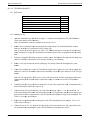
2.7.1 Load
d Return Cablles
T
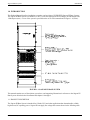
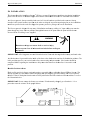
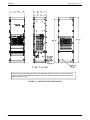
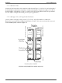
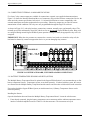
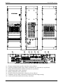
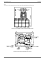
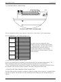
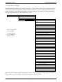
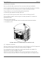
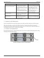
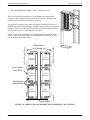
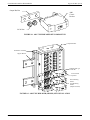
Terminate all load return cables at the reeturn bus (loaads) shown inn Figure 2-6. T
This bus is located on the rright of
tthe distributio
on area and co
onsists of up to
t three verticcally mountedd plates. The pplates have paairs of 1/4" annd 3/8"
tthreaded studss for 2-hole lu
ugging. Use th
he 1/4" studs for lower currrent loads prrotected with AM1 type brreakers.
T
The 3/8" studss are for high
her current loaads protected by GJ1 type bbreakers.
2.7.2 Load
d Supply Cables, AM1 Typ
pe Breaker Distribution
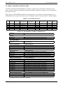
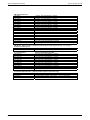
Distribu
ution
Cabliing
Tier 3
Group A
G
Tier 3
Group B
Tier 2
Group
G
A
Tier 2
Group B
Tier 1
Group A
G
Tier 1
Group B
Left Rear Corner of Rack
Left Front Corner of Rack
C
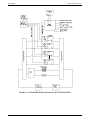
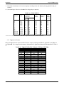
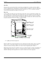
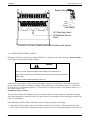
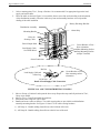
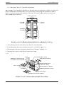
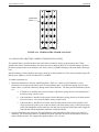
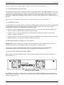
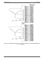
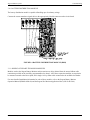
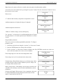
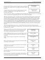
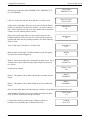
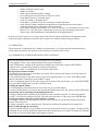
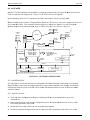
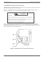
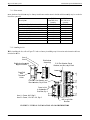
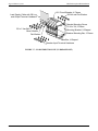
Connect custo
omer load sup
pply cabling in
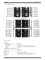
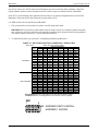
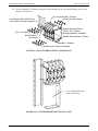
n order by Tier, Group, annd position nuumber as show
wn on the
B
Breaker/Fuse Layout label on the insidee of the distrib
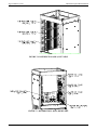
bution area dooor. Cables arre routed toward the nearesst rack
ccorner and theen upward, ass shown in Fig
gure 2-9.
Fuse Ala
arm
(FA) Wire
CD00031a
Distribution
Assemb
blies
Bus Barss
Distribution, Rack Left
ft Side
FIGURE 2-9 DISTRIIBUTION CA
ABLE ROUT
TING
P
PM990-8800-5
50, Issue 3
2-14