1
Front Matter
Sageon III Base System
RECEIVING INSTRUCTIONS
&
GENERAL EQUIPMENT INFORMATION
Please Note: For your protection, the following information and the product manual should be read and
thoroughly understood before unpacking, installing, or using the equipment.
UNIPOWER, LLC presents all equipment to the delivering carrier securely packed and in perfect
condition. Upon acceptance of the package from us, the delivering carrier assumed responsibility for its
safe arrival to you. Once you receive the equipment, it is your responsibility to document any damage the
carrier may have inflicted, and to file your claim promptly and accurately.
1.
PACKAGE INSPECTION
1.1
Examine the shipping crate or carton for any visible damage: punctures, dents, and any other signs of
possible internal damage.
1.2
Describe any damage or shortage on the receiving documents, and have the carrier sign their full name.
1.3
If your receiving freight bill notes that a Tip-N-Tell is attached to your freight, locate it. If the Tip-N-Tell
arrow has turned even partially blue, this means the freight has been tipped in transport. Make sure the
carrier notes this on your receipt before you sign for the freight.
2.
EQUIPMENT INSPECTION
2.1
Within fifteen days, open the crate and inspect the contents for damages. While unpacking, be careful not
to discard any equipment, parts, or manuals. If any damage is detected, call the delivering carrier to
determine appropriate action. They may require an inspection.
*SAVE ALL SHIPPING MATERIAL FOR THE INSPECTOR TO SEE!
2.2
After the inspection has been made, call UNIPOWER. We will determine if the equipment should be
returned to our plant for repair, or if some other method would be more expeditious. If it is determined
that the equipment should be returned to UNIPOWER, ask the delivering carrier to send the packages
back to UNIPOWER at the delivering carrier's expense.
2.3
If repair is necessary, we will invoice you for the repair so that you may submit the bill to the delivering
carrier with your claim form.
2.4
It is your responsibility to file a claim with the delivering carrier. Failure to properly file a claim for
shipping damages may void warranty service for any physical damages later reported for repair.
3.
HANDLING
Equipment can be universally heavy or top-heavy. Use adequate humanpower or equipment for handling.
Until the equipment is securely mounted, be careful to prevent the equipment from being accidentally
tipped over.
4.
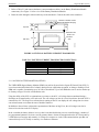
NAMEPLATE
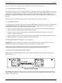
Each piece of UNIPOWER equipment is identified by a part number on the nameplate. Please refer to
this number in all correspondence with UNIPOWER.
PM990-8800-50, Issue 3
ii