1
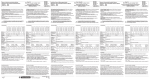
Model A1SX71 (6) Rated Input Voltage 5/12/24 VDC X00 X01 X02 X03 X04 X05 X06 X07 X08 X09 X0A X11 B19 A19 X12 B18 A18 X13 B17 A17 X14 B16 A16 X15 B15 A15 X16 B14 A14 X17 B13 A13 X18 B12 A12 X19 B11 A11 X1A B10 A10 X0B X0C X0D X0E X0F Vacant Vacant - X10 B20 A20 + COM COM X1B B9 A9 B8 A8 B7 A7 B6 A6 B5 A5 B4 A4 Vacant X1C X1D X1E X1F B3 A3 Vacant B2 A2 Vacant B1 A1 Vacant *1 The figure above shows the connections for the open collector (sink) type. B1 and B2 are connected internally. *1 La figure ci-dessus représente les connexions pour le type collecteur ouvert (dissipateur). B1 et B2 sont connectés à l'intérieur. TTL, LS-TTL, CMOS buffer (sink) connection TTL, LS-TTL, connexion tampon CMOS (dissipateur) Sensor (source) connection Connexion capteur (source) B20 + B20 + B2 B2 *2 The A and B pin number rows shown above are transposed with respect to the diagram of the A and B rows which is printed on the module. Remember that the A row pin numbers correspond to the B row of the module. *2 Les rangées de broches A et B ci-dessous correspondent aux rangées de broches marquées A et B sur le schéma imprimé sur le module. Noter que les numéros de broche de rangée A correspondent à la rangée B sur le module. English French English French Model Modèle Rated Load Voltage Tension nominale d'entrée Vacant Libre VDC V cc 68