1
TRC Development - Project The Real Cockpit
CCU User Manual
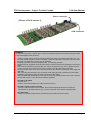
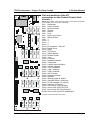
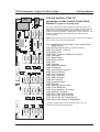
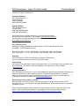
List and position of the I/O
connectors on the Central Control Unit
Version 1
CN38
CN27
CN22
CN32
CN26
CN21
CN34
CN37
CN25
CN20
CN31
CN29
CN24
CN19
CN30
CN28
CN23
Version1.2 – May 2004
Handbrake
Avionics Switch
Quartz Counter
Throttle
Mixture
Prop
Light Control Input
Master Switch
*)
*)
*)
*)
Fuel selector + Shut off
Digital Clock
Flaps
Trim wheel
Starter Switch
Rudder Pedals
Yoke
Compass
Airspeed Indicator
Tachometer
Vertical Speed Indicator
Attitude Indicator
Turn Coordinator
VOR 1 Indicator
VOR 2 Indicator
ADF Indicator
Heading Indicator
Altimeter
Warning Lights & Switch
Autopilot Switch + Warnings
Circuit breakers (15 outputs)
Switches (16 inputs)
Servo Ctrld. Fuel Left/Right
Servo Ctrld. EGT/Fuel Flow
Servo Ctrld. Oil Temp/Pressure
Servo Ctrld. Suction G./AMindicator
CN17
CN16
CN15
CN14
CN13
CN1 CN2 CN3
CN6
CN7
CN8
CN9
CN10
CN11
CN12
CN43
CN18
CN33
CN36
*) These connections have no function.
CN35
CN5
CN1
CN2
CN3
CN4
CN5
CN6
CN7
CN8
CN9
CN10
CN11
CN12
CN13
CN14
CN15
CN16
CN17
CN18
CN19
CN20
CN21
CN22
CN23
CN24
CN25
CN26
CN27
CN28
CN29
CN30
CN31
CN32
CN33
CN34
CN35
CN36
CN37
CN38
CN4
NOTE: The position of the text on the picture on the left is not identical
to the position of the text on the board itself.
Page 8